US11045394B2 - Mobile medical drug management systems and methods - Google Patents
Mobile medical drug management systems and methods Download PDFInfo
- Publication number
- US11045394B2 US11045394B2 US16/297,021 US201916297021A US11045394B2 US 11045394 B2 US11045394 B2 US 11045394B2 US 201916297021 A US201916297021 A US 201916297021A US 11045394 B2 US11045394 B2 US 11045394B2
- Authority
- US
- United States
- Prior art keywords
- drug
- vial
- rack system
- seat
- drug rack
- Prior art date
- Legal status (The legal status is an assumption and is not a legal conclusion. Google has not performed a legal analysis and makes no representation as to the accuracy of the status listed.)
- Active, expires
Links
- 239000003814 drug Substances 0.000 title claims abstract description 202
- 229940079593 drug Drugs 0.000 title claims abstract description 202
- 238000000034 method Methods 0.000 title abstract description 14
- 230000007246 mechanism Effects 0.000 claims description 15
- 230000007704 transition Effects 0.000 claims description 8
- 238000004891 communication Methods 0.000 abstract description 22
- 239000004081 narcotic agent Substances 0.000 abstract description 5
- 230000003993 interaction Effects 0.000 description 6
- 230000036772 blood pressure Effects 0.000 description 3
- 238000004590 computer program Methods 0.000 description 3
- 239000000463 material Substances 0.000 description 3
- 230000003287 optical effect Effects 0.000 description 3
- 241000219823 Medicago Species 0.000 description 2
- 230000008901 benefit Effects 0.000 description 2
- 230000001769 paralizing effect Effects 0.000 description 2
- 239000000932 sedative agent Substances 0.000 description 2
- 230000001624 sedative effect Effects 0.000 description 2
- 230000001052 transient effect Effects 0.000 description 2
- FBPFZTCFMRRESA-JGWLITMVSA-N D-glucitol Chemical compound OC[C@H](O)[C@@H](O)[C@H](O)[C@H](O)CO FBPFZTCFMRRESA-JGWLITMVSA-N 0.000 description 1
- 208000004221 Multiple Trauma Diseases 0.000 description 1
- 229910003798 SPO2 Inorganic materials 0.000 description 1
- 101100478210 Schizosaccharomyces pombe (strain 972 / ATCC 24843) spo2 gene Proteins 0.000 description 1
- 238000007792 addition Methods 0.000 description 1
- 230000002411 adverse Effects 0.000 description 1
- QVGXLLKOCUKJST-UHFFFAOYSA-N atomic oxygen Chemical compound [O] QVGXLLKOCUKJST-UHFFFAOYSA-N 0.000 description 1
- 230000005540 biological transmission Effects 0.000 description 1
- 230000000295 complement effect Effects 0.000 description 1
- 230000008878 coupling Effects 0.000 description 1
- 238000010168 coupling process Methods 0.000 description 1
- 238000005859 coupling reaction Methods 0.000 description 1
- 230000002526 effect on cardiovascular system Effects 0.000 description 1
- 230000007613 environmental effect Effects 0.000 description 1
- 239000012530 fluid Substances 0.000 description 1
- 239000011521 glass Substances 0.000 description 1
- 230000036541 health Effects 0.000 description 1
- 238000005286 illumination Methods 0.000 description 1
- 239000007788 liquid Substances 0.000 description 1
- 239000004973 liquid crystal related substance Substances 0.000 description 1
- 238000012986 modification Methods 0.000 description 1
- 230000004048 modification Effects 0.000 description 1
- 230000003533 narcotic effect Effects 0.000 description 1
- 230000004297 night vision Effects 0.000 description 1
- 229910052760 oxygen Inorganic materials 0.000 description 1
- 239000001301 oxygen Substances 0.000 description 1
- 230000008569 process Effects 0.000 description 1
- 230000010076 replication Effects 0.000 description 1
- 238000012827 research and development Methods 0.000 description 1
- 230000029058 respiratory gaseous exchange Effects 0.000 description 1
- 230000001953 sensory effect Effects 0.000 description 1
- 239000012780 transparent material Substances 0.000 description 1
- 230000000007 visual effect Effects 0.000 description 1
Images


Classifications
-
- A—HUMAN NECESSITIES
- A61—MEDICAL OR VETERINARY SCIENCE; HYGIENE
- A61K—PREPARATIONS FOR MEDICAL, DENTAL OR TOILETRY PURPOSES
- A61K31/00—Medicinal preparations containing organic active ingredients
- A61K31/33—Heterocyclic compounds
- A61K31/395—Heterocyclic compounds having nitrogen as a ring hetero atom, e.g. guanethidine or rifamycins
- A61K31/435—Heterocyclic compounds having nitrogen as a ring hetero atom, e.g. guanethidine or rifamycins having six-membered rings with one nitrogen as the only ring hetero atom
- A61K31/47—Quinolines; Isoquinolines
- A61K31/485—Morphinan derivatives, e.g. morphine, codeine
-
- A—HUMAN NECESSITIES
- A61—MEDICAL OR VETERINARY SCIENCE; HYGIENE
- A61B—DIAGNOSIS; SURGERY; IDENTIFICATION
- A61B50/00—Containers, covers, furniture or holders specially adapted for surgical or diagnostic appliances or instruments, e.g. sterile covers
- A61B50/20—Holders specially adapted for surgical or diagnostic appliances or instruments
- A61B50/22—Racks
-
- A—HUMAN NECESSITIES
- A61—MEDICAL OR VETERINARY SCIENCE; HYGIENE
- A61J—CONTAINERS SPECIALLY ADAPTED FOR MEDICAL OR PHARMACEUTICAL PURPOSES; DEVICES OR METHODS SPECIALLY ADAPTED FOR BRINGING PHARMACEUTICAL PRODUCTS INTO PARTICULAR PHYSICAL OR ADMINISTERING FORMS; DEVICES FOR ADMINISTERING FOOD OR MEDICINES ORALLY; BABY COMFORTERS; DEVICES FOR RECEIVING SPITTLE
- A61J1/00—Containers specially adapted for medical or pharmaceutical purposes
- A61J1/14—Details; Accessories therefor
- A61J1/16—Holders for containers
-
- A—HUMAN NECESSITIES
- A61—MEDICAL OR VETERINARY SCIENCE; HYGIENE
- A61J—CONTAINERS SPECIALLY ADAPTED FOR MEDICAL OR PHARMACEUTICAL PURPOSES; DEVICES OR METHODS SPECIALLY ADAPTED FOR BRINGING PHARMACEUTICAL PRODUCTS INTO PARTICULAR PHYSICAL OR ADMINISTERING FORMS; DEVICES FOR ADMINISTERING FOOD OR MEDICINES ORALLY; BABY COMFORTERS; DEVICES FOR RECEIVING SPITTLE
- A61J7/00—Devices for administering medicines orally, e.g. spoons; Pill counting devices; Arrangements for time indication or reminder for taking medicine
- A61J7/0069—Trays for holding or distributing medicines
-
- G—PHYSICS
- G16—INFORMATION AND COMMUNICATION TECHNOLOGY [ICT] SPECIALLY ADAPTED FOR SPECIFIC APPLICATION FIELDS
- G16H—HEALTHCARE INFORMATICS, i.e. INFORMATION AND COMMUNICATION TECHNOLOGY [ICT] SPECIALLY ADAPTED FOR THE HANDLING OR PROCESSING OF MEDICAL OR HEALTHCARE DATA
- G16H15/00—ICT specially adapted for medical reports, e.g. generation or transmission thereof
-
- G—PHYSICS
- G16—INFORMATION AND COMMUNICATION TECHNOLOGY [ICT] SPECIALLY ADAPTED FOR SPECIFIC APPLICATION FIELDS
- G16H—HEALTHCARE INFORMATICS, i.e. INFORMATION AND COMMUNICATION TECHNOLOGY [ICT] SPECIALLY ADAPTED FOR THE HANDLING OR PROCESSING OF MEDICAL OR HEALTHCARE DATA
- G16H20/00—ICT specially adapted for therapies or health-improving plans, e.g. for handling prescriptions, for steering therapy or for monitoring patient compliance
- G16H20/10—ICT specially adapted for therapies or health-improving plans, e.g. for handling prescriptions, for steering therapy or for monitoring patient compliance relating to drugs or medications, e.g. for ensuring correct administration to patients
-
- G—PHYSICS
- G16—INFORMATION AND COMMUNICATION TECHNOLOGY [ICT] SPECIALLY ADAPTED FOR SPECIFIC APPLICATION FIELDS
- G16H—HEALTHCARE INFORMATICS, i.e. INFORMATION AND COMMUNICATION TECHNOLOGY [ICT] SPECIALLY ADAPTED FOR THE HANDLING OR PROCESSING OF MEDICAL OR HEALTHCARE DATA
- G16H40/00—ICT specially adapted for the management or administration of healthcare resources or facilities; ICT specially adapted for the management or operation of medical equipment or devices
- G16H40/40—ICT specially adapted for the management or administration of healthcare resources or facilities; ICT specially adapted for the management or operation of medical equipment or devices for the management of medical equipment or devices, e.g. scheduling maintenance or upgrades
-
- A—HUMAN NECESSITIES
- A61—MEDICAL OR VETERINARY SCIENCE; HYGIENE
- A61B—DIAGNOSIS; SURGERY; IDENTIFICATION
- A61B50/00—Containers, covers, furniture or holders specially adapted for surgical or diagnostic appliances or instruments, e.g. sterile covers
- A61B50/30—Containers specially adapted for packaging, protecting, dispensing, collecting or disposing of surgical or diagnostic appliances or instruments
- A61B50/31—Carrying cases or bags, e.g. doctors' bags
-
- A—HUMAN NECESSITIES
- A61—MEDICAL OR VETERINARY SCIENCE; HYGIENE
- A61J—CONTAINERS SPECIALLY ADAPTED FOR MEDICAL OR PHARMACEUTICAL PURPOSES; DEVICES OR METHODS SPECIALLY ADAPTED FOR BRINGING PHARMACEUTICAL PRODUCTS INTO PARTICULAR PHYSICAL OR ADMINISTERING FORMS; DEVICES FOR ADMINISTERING FOOD OR MEDICINES ORALLY; BABY COMFORTERS; DEVICES FOR RECEIVING SPITTLE
- A61J1/00—Containers specially adapted for medical or pharmaceutical purposes
- A61J1/05—Containers specially adapted for medical or pharmaceutical purposes for collecting, storing or administering blood, plasma or medical fluids ; Infusion or perfusion containers
- A61J1/06—Ampoules or carpules
- A61J1/065—Rigid ampoules, e.g. glass ampoules
-
- A—HUMAN NECESSITIES
- A61—MEDICAL OR VETERINARY SCIENCE; HYGIENE
- A61J—CONTAINERS SPECIALLY ADAPTED FOR MEDICAL OR PHARMACEUTICAL PURPOSES; DEVICES OR METHODS SPECIALLY ADAPTED FOR BRINGING PHARMACEUTICAL PRODUCTS INTO PARTICULAR PHYSICAL OR ADMINISTERING FORMS; DEVICES FOR ADMINISTERING FOOD OR MEDICINES ORALLY; BABY COMFORTERS; DEVICES FOR RECEIVING SPITTLE
- A61J7/00—Devices for administering medicines orally, e.g. spoons; Pill counting devices; Arrangements for time indication or reminder for taking medicine
- A61J7/0076—Medicament distribution means
-
- A—HUMAN NECESSITIES
- A61—MEDICAL OR VETERINARY SCIENCE; HYGIENE
- A61J—CONTAINERS SPECIALLY ADAPTED FOR MEDICAL OR PHARMACEUTICAL PURPOSES; DEVICES OR METHODS SPECIALLY ADAPTED FOR BRINGING PHARMACEUTICAL PRODUCTS INTO PARTICULAR PHYSICAL OR ADMINISTERING FORMS; DEVICES FOR ADMINISTERING FOOD OR MEDICINES ORALLY; BABY COMFORTERS; DEVICES FOR RECEIVING SPITTLE
- A61J7/00—Devices for administering medicines orally, e.g. spoons; Pill counting devices; Arrangements for time indication or reminder for taking medicine
- A61J7/04—Arrangements for time indication or reminder for taking medicine, e.g. programmed dispensers
-
- G—PHYSICS
- G16—INFORMATION AND COMMUNICATION TECHNOLOGY [ICT] SPECIALLY ADAPTED FOR SPECIFIC APPLICATION FIELDS
- G16H—HEALTHCARE INFORMATICS, i.e. INFORMATION AND COMMUNICATION TECHNOLOGY [ICT] SPECIALLY ADAPTED FOR THE HANDLING OR PROCESSING OF MEDICAL OR HEALTHCARE DATA
- G16H10/00—ICT specially adapted for the handling or processing of patient-related medical or healthcare data
- G16H10/60—ICT specially adapted for the handling or processing of patient-related medical or healthcare data for patient-specific data, e.g. for electronic patient records
Definitions
- the present disclosure relates to documentation of prehospital patient care reports and communication of patient status to a receiving medical treatment facility.
- ambulatory medical care providers such as military medics
- the medical care provider typically must write and/or maintain a log of narcotic use post-mission.
- the medical care provider may suffer penalties, such as job or pay loss, if the narcotics log is found to be inaccurate.
- the medic care provider is typically issued pre-mission, loose drug vials in a hand-held case with a commercial off-the-shelf key lock to maintain drug security.
- the medic must hold these very small vials in his/her hands and must often try to insert the needle in a very high vibration environment of either an air or ground MEDEVAC. Finger sticks, loss of drug vials, over/under-dosing of patients are common and unfortunate occurrences.
- the systems and methods relate to systems and methods for managing, recording, and administering drugs such as narcotics in an ambulatory and/or emergency environment.
- the systems and methods include a drug rack that includes various features for securely managing the administration of drugs.
- the drug rack is particularly suited for an environment outside of a hospital such as a prehospital environment. It can be used on military or emergency missions and is particularly suited for the harsh and unpredictable environments of such missions.
- the drug rack is communicatively and/or mechanically coupled to a weight-based drug calculator to assist in proper, weight-based dosage of drug by a medical provider.
- the rack also includes one or more mechanisms for securing the drugs pre/during/post mission for accountability and safer usability. This also adds safety measures to assist the care provider in selecting the proper drug during the mission.
- the system is also configured to maintain a log of the drugs pulled from the rack or otherwise manipulated for improved and accurate post-mission drug inventory. The system can also maintain an accurate and up-to-date patient health record.
- the drug rack includes one or more slots or seats that can contain standard-issue drug vials or containers, such as pain management, sedative, and paralytic vials (for example, 10 mL multi-dose, and 2 mL single-dose vials).
- the rack also includes a security mechanism, such as lock bar, to secure entry or access to the drug rack for mounting and unmounting the drug vials.
- the lock bar does not necessarily inhibit access to the vials for fluid withdrawal.
- the drug rack includes a primary security mechanism for medication withdrawal from the vials in the form of small access doors. Under normal use cases, these doors cannot be manually opened without gaining access via a software interface. Rather, the user must rely on an associated software interface to obtain access to the contents of the drug vials.
- the rack includes one or more identifiers, such as light emitting diode (LED) indicators, that assist a medical care provider in identifying a proper drug for use with a patient.
- the drug rack may also include an electronic and/or mechanical access feature, such as one or more access doors, that automatically open to assist the medical care provider in accessing and identifying which drug vial was selected for administration on the patient.
- the access doors may automatically open when a corresponding drug is selected via a software user interface.
- the system may include or otherwise be coupled to software that provides recommended dosages, and software buttons to open the access door(s) to the associated drug on the rack, which also illuminates an indicator light.
- the software buttons aid in the security of the drugs in that a user must have access to a user device, such as a tablet, and also be properly logged in as an authorized medic in order to activate the doors of the drug rack.
- an additional software button may be used to record the drug given and to also close the access door to the drug vial. The recorded drug's actual volume and dosage may be automatically captured during this process.
- the system may also be used scan the type of drug in the vial holder and to also automatically measure an amount of drug that was actually pulled from the vial.
- the system can also include wireless communication capabilities, such as for example, Bluetooth and Ultra-Wideband wireless connectivity to the drug rack and to a remote location.
- FIG. 1 shows a schematic representation of a system for documentation and management of prehospital patient care reports and communication of patient status to a receiving medical treatment facility.
- FIG. 2 shows a mobile container system that can be carried by a medical care provider for use in missions such as military and emergency missions outside of a hospital.
- FIG. 3 shows a drug rack that can be coupled to the mobile container system.
- FIG. 4 shows a mounting clip for the drug rack of a mobile medication management system.
- the drug rack itself may also be referred to as a mobile medication management system or as a portion thereof.
- FIG. 5 shows the drug rack mounted to Modular Lightweight Load-carrying Equipment (“MOLLE”).
- MOLLE Modular Lightweight Load-carrying Equipment
- FIGS. 6 and 7 show bottom views of the drug rack.
- FIG. 8 shows an example user interface of the system.
- FIGS. 9 and 10 show perspective views of another embodiment of a drug rack.
- FIGS. 11 and 12 show the drug rack of FIGS. 9 and 10 with a lid in an open state.
- the system includes a drug rack that can be used to securely manage the storage, access, and distribution of drugs such as narcotics.
- the drug rack is portable and can be carried by a user, such as a medic, in connection with missions such as military and emergency missions.
- FIG. 1 schematically shows an exemplary, high-level representation of a system for documentation and management of prehospital patient care reports and communication of patient status to a receiving medical facility 120 .
- the system includes a mobile container system 105 (also referred to as a transport telemedicine system), which is described in more detail below with reference to FIG. 2 .
- the mobile container system 105 is of a size such that it can be carried by a person, such as a medical care provider (e.g., a medic).
- the mobile container system 105 is also sized to be carried and transported in a mobile vehicle 110 , such as a helicopter.
- the mobile container system 105 includes or can be coupled to a communication device, such as a wireless transmitter, that enables the mobile container system 105 , to communicate with the medical facility 120 , such as via communication with a satellite 150 and/or communication over a communication network such as the Internet.
- a communication device such as a wireless transmitter
- the mobile container system 105 or any other component of the system is configured to communicate pursuant to the features described in the following U.S. patent applications, which are incorporated by reference in their entirety: (1) U.S. patent application Ser. No. 15/803,220 entitled “EXTENDED RANGE COMMUNICATIONS FOR ULTRA-WIDEBAND NETWORK NODES” and filed on Nov. 3, 2017; and (2) U.S. patent application Ser. No. 15/650,095 entitled “MULTI-BROKER MESSAGING AND TELEMEDICINE DATABASE REPLICATION” and filed on Jul. 14, 2017.
- the system of FIG. 1 provides access to a user interface 125 that can provide user interaction with data collected by the mobile container system 105 . Such interaction can include, for example, viewing the data as well as entering and modifying data.
- the user interface shown in FIG. 1 is a dashboard-like interface to be used by remote care providers to gain an overview of the condition and status of all patients associated with the mobile container system.
- the mobile container system 105 is mechanically and/or wirelessly coupled to one or more devices 100 , which can include a drug rack 305 ( FIG. 3 ) that can be used to securely manage the storage, access, and distribution of drugs, as described in detail below.
- devices 100 which can include a drug rack 305 ( FIG. 3 ) that can be used to securely manage the storage, access, and distribution of drugs, as described in detail below.
- the devices 100 can also include other types of devices, such as medical device that may be connected to the device mobile container system 105 either via a physical or wireless connection.
- the connected medical device(s) may include, for example, any number and combination of devices such as: EKG monitor, blood pressure monitor, heart rate monitor, ventilator, defibrillator, IV pump, EEG device, oxygen sensor, cardiovascular reserve index monitor or other similar devices.
- the mobile container system 105 may be used at a point of care location, which can be any location where a care provider is providing medical care to a patient.
- the point of care location is an emergency location such as a vehicle crash, battlefield or disaster site.
- Such environments may have limited communication capabilities that may adversely affect the ability to transmit data and may also have extreme environmental conditions.
- the point of care location may be any location that is remote from the point of care location. In an example, the remote location is at least more than several miles away from the medical facility 120 .
- FIG. 2 shows the mobile container system 105 , which includes a container 210 that can be carried by a medical care provider.
- the mobile container system 105 is communicatively coupled to a user device 215 , which can be contained within or otherwise coupled to the container 210 .
- the user device 215 can be any type of device that the care provider uses to enter, record, store, view and/or maintain data related to the care of the patient.
- the user device 215 may be, for example, a laptop computer, mobile phone, tablet, data pad, etc.
- the user device 215 generally includes a data input element such as a keypad and/or touch screen.
- the device 215 includes voice recognition software that permits the user to verbally enter data into the device 215 .
- the user device 215 is held, controlled and/or operated by one or more transport personnel, such as a medic in an emergency environment.
- the user can input data into the user device 215 via a user interface.
- the user device 215 is configured to receive data from a user, wherein the data may relate to aspects of the patient, such as height, weight, blood pressure, or any data related to the patient.
- FIG. 2 also shows other possible components such as an Athena GTX WVSM patient care device, which provides the following telemetric values: 3 lead ECG/EKG, Blood Pressure, SPO2 and heart rate.
- Another component can include a biomodule device, such as a Zephyr BioModule, which provides respiration rate, 2 lead ECG/EKG, and Accelerometer data.
- a communication component may be coupled to the mobile container system 105 .
- the communication component can be any device that is configured to transmit data to a remote location via a communication link, such as a line of sight, satellite or any other type of wireless communication link to the remote location.
- the communication link may include the Internet, public switched telephone network (PSTN), a private network, etc.
- PSTN public switched telephone network
- the communication component may include any of a variety of communication devices that are configured to transmit data.
- the communication component may include one or more antennas, modems, amplifiers, radios, or other types of transceivers, etc.
- the communication component enables the mobile container system 105 to transmit data from a database via wireless transmission (e.g., radio) to an external network in accordance with configured specifications, with the end user being another party such as a medical facility.
- the mobile container system 105 includes the drug rack 305 , which is configured to manage the storage, access, and distribution of drugs.
- FIG. 3 shows a perspective view of an example embodiment of the drug rack 305 .
- the drug rack 305 includes an outer housing 310 that is sized and shaped to contain and/or store one or more drug vials 315 .
- the outer housing 305 can be any of a variety of shapes including the rectangular shape shown in FIG. 3 .
- the drug rack 305 has a size of 5 inches wide by 2.5 inches tall, by 2.5 inches deep and weighs no more than about 0.6 pounds.
- the drug rack 305 is contained within or otherwise includes a housing with a lid that can be opened to exposed contents of the drug rack 305 .
- the drug rack 305 is sized to contain four drug vials 315 , which can be of equal or varying size relative to one another.
- the vials can be 10 mL multi-dose or 2 mL single-dose vials although the size of the vials can vary.
- the housing 310 can be sized to contain any quantity of vials although the preference is that the quantity be limited so that the housing is of a size than can be transported and/or easily carried by a user.
- the housing 310 contains no more than three, four, five, six, and up to ten vials although this may vary.
- the housing 310 is configured such that it defines at least one slot or seat for each of the drug vials 315 .
- the seats can be configured to receive therein a drug vial of various sizes, such as a large drug vial and a smaller drug vial.
- the drug vials 315 are arranged in one or more rows of drug vials as shown in FIG. 3 although the spatial arrangement of the drug vials can vary.
- a retaining member, such as a lock bar 320 is movably attached to the housing 310 such that, in a closed state, the lock bar 320 , retains or secures the vials 315 within their respective seats in the housing 310 .
- the lock bar 320 can move relative to the housing 310 , such as in a pivoting or rotating manner, to an open state wherein the lock bar 320 does not impede or otherwise prevent the drug vials 315 from being removed from the housing 310 .
- the lock bar 320 is positioned such that a vial, when seated in its seat, is interposed between the lock bar 320 and the seat so that the lock bar 320 prevents the vial from being removed from the seat when the lock bar is properly positioned.
- the drug rack 305 can include a single lock bar 320 that collectively secures all the drug vials 315 as shown, or it can include a separate, dedicated lock bar for each of (or a subset of) the drug vials in the drug rack 305 .
- the lock bar 320 can be lockingly secured in the closed state such as via a mechanical or electromechanical lock for security of the drugs contained within the drug rack 305 .
- the drug rack 305 can include a mounting clip 325 that is attached to the housing 310 .
- the mounting clip 325 can be used to secure or otherwise mount the drug rack 305 to another object.
- FIG. 4 shows the mounting clip 325 and
- FIG. 5 shows the drug rack 305 mounted to a MOLLE as an example.
- FIG. 6 shows a bottom view of the drug rack 305 .
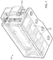
- FIG. 7 shows a bottom view with the drug rack being partially transparent so as to illustrate internal components of the drug rack.
- an opening or port 605 is associated with each of the drug vials 315 at the bottom wall of the housing.
- Each port 605 provides an accessway by which a user, such as a medic, can access the contents of the respective drug vial 315 .
- Each port 605 can transition between an open state and a closed state. Port 605 a is shown in the open state while port 605 b is shown in the closed state. When the port is in the open state, the contents of the respective drug vial are accessible by the user.
- FIG. 7 shows an example mechanism by which the ports 605 can transition between the open and closed states.
- Each port 605 has an associated door 705 that is movably positioned within the drug rack 305 .
- Each door 705 can slidably transition between the closed state wherein the door 705 covers or otherwise blocks the respective port, and an open state wherein the door 705 does not cover or otherwise block the respective port.
- the door 705 a is in the open state while the remainder of the doors 705 are in the closed state.
- the drug rack 305 can include electromechanical components that are coupled to the doors 705 and the lock bar 320 for controlling these components between the open and closed states.
- the drug rack can also include software to automatically control these components, such as via interaction with a user and/or based upon satisfaction of predetermined conditions.
- the drug rack 305 can include features such a lights, sounds, and tactile feedback to provide the user with indications as to the availability of the drug, type of drug, dosage information for the drug, how much drug has been used, etc.
- the drug rack can include, for example, one or more multi-color LED drug indicator lights that provide a color coded back light depending on the type of drug contained in the vials.
- the lights can be color-coded such as Blue/Pain, Orange/Sedative, Purple/Paralytic.
- the software can be coupled to a user interface, such as the example user interface shown in FIG. 8 .
- the user interface can include data related to the drug vials and can also include features that enable the user to interact with the drug rack, such as to open/close/lock/unlock features of the drug rack.
- the access doors and/or the lock bar can be configured via software to automatically open after the care provider selects a drug to administer via the user interface.
- the software can also include a weight-based recommended drug calculator that can read weight automatically from a digital/wireless scale coupled to the system.
- the drug rack software can also automatically detect the drug type in a vial via a bar code scan and also the volume/dosage pulled from a vial.
- FIGS. 9 and 10 show perspective views of another embodiment of the drug rack 305 .
- This embodiment includes an outer housing 910 with a movable lid 920 that transitions between an open and closed state.
- the lid 920 covers the drug vials so as to prevent access to the drug vials.
- the lid does not cover the drug vials and does not prevent access to the drug vials. Rather, the lid provides a platform or surface that provides a location where a user can place instruments, such as needles, when accessing the drug vials.
- FIGS. 9 and 10 show the lid 920 in the closed state.
- the lid 920 is at least partially made of a transparent material such that a user can view the drug vials contained therein even when the lid is closed.
- the drug rack 305 can include components such as a power (or “on/off”) switch 925 .
- the drug rack 305 can also include a port 930 , such as a USB port, for charging the drug rack and or coupling a USB device to the drug rack 305 .
- the outer housing 910 and lid 920 can include an interface such as a pair of holes through which a tie element can be inserted and tied for locking the lid closed.
- the outer housing 910 can also include other components such as magnets for securing the lid 920 in the closed state.
- the drug rack 305 can include a tightening mechanism 1005 that a user can actuate to tighten and to also release tension on one or more elongated members such as cables or wires 1012 (or other actuation component) that individually or collectively serve as a retaining member or locking element for vials contained within the drug rack 305 , as described more fully below.
- the wires 1012 wrap around vials contained within the drug rack 305 and can be tightened to lockingly secure the vials within the drug rack 305 .
- the tightening mechanism includes a ratcheting device that can be actuated, such as via rotation or other movement, to place the wires in tension and/or release the wires from tension.
- the ratcheting device includes a rotatable knob.
- FIG. 11 shows the drug rack 305 with the lid 920 in the open state wherein the lid is open relative to the outer housing 910 so as to expose the vials 315 .
- the drug rack 305 is in an example orientation in which a user, such as a medic, can use the drug rack 305 .
- the lid 920 is coupled to the outer housing 910 via one or more hinges 1105 that enable the lid 920 to rotate between the open state and the closed state. It should be appreciated that other mechanisms aside from rotatable hinges can be used to enable the transition of the lid between the open and closed states.
- the lid 920 defines a flat or substantially flat, horizontal platform or surface 1110 that defines a space where a user, such as a medic, can rest his or her hands as the vials are being accessed.
- the surface 1110 also provides a platform upon which the user can also place one or more items, such as a needle.
- the flat surface 1110 aids in the medic inserting a needle into a vial such as during a high vibration environment.
- the lid 920 and/or the outer housing 910 can include one or more securing elements, such as magnets, to maintain the lid 920 in an open or closed state.
- the vials 315 are positioned relative to the surface 1110 such that ends of the vials 315 are facing and immediately adjacent to the surface 1110 .
- an open or access portion (such as where a needle can be inserted) of the vial 315 is immediately adjacent the surface 1110 , such as abutting and/or contacting the surface or within an inch or two of the surfaces. This permits the user to easily access both the surface 1110 and the vials 315 .
- each vial 315 is seated within a corresponding slot or seat.
- the drug rack 305 orients each vial 315 so that a top portion or access portion of the vial is presented to a user for convenient access.
- the seat can be shaped to correspond or complement the shape of the vial so that the vial can sit flush within the respective seat.
- Each vial has a corresponding saddle 1120 that abuts, grabs, or otherwise stabilizes or the vial when seated in its seat.
- the saddle 1120 can be tightened about its respective vial to lock the vial within its seat.
- the saddle 1120 can be made of a material that is flexible or malleable such that the saddle can conform to the shape of the respective vial when the saddle is tightened over the vial.
- the saddles 1120 can be tightened about their respective vials to lock the vials within their seats.
- the wires 1012 FIGS. 10 and 11
- the wires 1012 are threaded through the saddles and also threaded through at least a portion of the drug rack so as to secure the drug vials 315 relative to the drug rack.
- the wires 1012 can be placed in tension to exert a force that constrains the saddles 1120 and their respective vials in place within their seats.
- the actuator 1005 ( FIG. 10 ) can be used to tighten and release the tension on the wires 1012 .
- the actuator 1005 is part of a tightening mechanism, such as the tightening mechanism described in U.S. Pat. No. 5,934,599, which is incorporated herein by reference in its entirety.
- FIG. 12 shows another view of the drug rack 305 .
- the lid and a portion of the outer housing are not shown in FIG. 12 for clarity of illustration.
- the drug rack 305 can include one or more multi-color LED drug indicator lights that provide a color coded back light depending on the type of drug contained in the vials.
- the one or more LEDs 1205 can be located on the drug rack 305 at or near a bottom region of each vial 315 . When illuminated, an LED emits light through a clear bottom region of the drug vial. The light refracts in the material of the vial (such as glass) and within the material inside the vial (such as liquid) so as to make the vial glow.
- the drug rack can include infrared capabilities and/or night vision capabilities that utilize infrared LEDs for illumination of the vial(s).
- a user such an emergency medic
- the location can be an emergency location such as a disaster site or a battle site.
- the user can carry the mobile container system 105 or a portion thereof during transport or can also mount the mobile container system 105 on the vehicle.
- the user can carry the mobile container system 105 or a portion thereof on his or her body without assistance from a transport device such as a cart.
- the user can then treat a patient by accessing the user interface.
- the user can gain access to the contents of one or more drug vials of the drug rack via interaction with the user interface, which may request credentials or other security access requirements.
- the mobile container system 105 can locally or remotely records or otherwise memorialize data related to the drug or contents accessed via the vial. For example, the system can record, via the drug rack, that a specific drug was administered at a certain time, the time the drug was given, the name or other data related to the patient, the dosage amount, etc.
- One or more aspects or features of the subject matter described herein may be realized in digital electronic circuitry, integrated circuitry, specially designed ASICs (application specific integrated circuits), computer hardware, firmware, software, and/or combinations thereof.
- ASICs application specific integrated circuits
- These various implementations may include implementation in one or more computer programs that are executable and/or interpretable on a programmable system including at least one programmable processor, which may be special or general purpose, coupled to receive data and instructions from, and to transmit data and instructions to, a storage system, at least one input device (e.g., mouse, touch screen, etc.), and at least one output device.
- machine-readable medium refers to any computer program product, apparatus and/or device, such as for example magnetic discs, optical disks, memory, and Programmable Logic Devices (PLDs), used to provide machine instructions and/or data to a programmable processor, including a machine-readable medium that receives machine instructions as a machine-readable signal.
- machine-readable signal refers to any signal used to provide machine instructions and/or data to a programmable processor.
- the machine-readable medium can store such machine instructions non-transitorily, such as for example as would a non-transient solid-state memory or a magnetic hard drive or any equivalent storage medium.
- the machine-readable medium can alternatively or additionally store such machine instructions in a transient manner, such as for example as would a processor cache or other random-access memory associated with one or more physical processor cores.
- the subject matter described herein can be implemented on a device having a display device, such as for example a liquid crystal display (LCD) monitor for displaying information to the user and a keyboard and a input device, such as for example a mouse or a trackball, by which the user may provide input to the device.
- a display device such as for example a liquid crystal display (LCD) monitor for displaying information to the user and a keyboard and a input device, such as for example a mouse or a trackball, by which the user may provide input to the device.
- LCD liquid crystal display
- a keyboard and a input device such as for example a mouse or a trackball
- Other kinds of devices can be used to provide for interaction with a user as well.
- feedback provided to the user can be any form of sensory feedback, such as for example visual feedback, auditory feedback, or tactile feedback; and input from the user may be received in any form, including, but not limited to, acoustic, speech, or tactile input.
- touch screens or other touch-sensitive devices such as single or multi-point resistive or capacitive trackpads, voice recognition hardware and software, optical scanners, optical pointers, digital image capture devices and associated interpretation software, and the like.
Abstract
Description
Claims (38)
Priority Applications (2)
| Application Number | Priority Date | Filing Date | Title |
|---|---|---|---|
| US16/297,021 US11045394B2 (en) | 2018-05-09 | 2019-03-08 | Mobile medical drug management systems and methods |
| US17/339,588 US11529290B2 (en) | 2018-05-09 | 2021-06-04 | Mobile medical drug management systems and methods |
Applications Claiming Priority (2)
| Application Number | Priority Date | Filing Date | Title |
|---|---|---|---|
| US201862669154P | 2018-05-09 | 2018-05-09 | |
| US16/297,021 US11045394B2 (en) | 2018-05-09 | 2019-03-08 | Mobile medical drug management systems and methods |
Related Child Applications (1)
| Application Number | Title | Priority Date | Filing Date |
|---|---|---|---|
| US17/339,588 Continuation US11529290B2 (en) | 2018-05-09 | 2021-06-04 | Mobile medical drug management systems and methods |
Publications (2)
| Publication Number | Publication Date |
|---|---|
| US20190343727A1 US20190343727A1 (en) | 2019-11-14 |
| US11045394B2 true US11045394B2 (en) | 2021-06-29 |
Family
ID=68463813
Family Applications (2)
| Application Number | Title | Priority Date | Filing Date |
|---|---|---|---|
| US16/297,021 Active 2039-03-28 US11045394B2 (en) | 2018-05-09 | 2019-03-08 | Mobile medical drug management systems and methods |
| US17/339,588 Active 2039-03-23 US11529290B2 (en) | 2018-05-09 | 2021-06-04 | Mobile medical drug management systems and methods |
Family Applications After (1)
| Application Number | Title | Priority Date | Filing Date |
|---|---|---|---|
| US17/339,588 Active 2039-03-23 US11529290B2 (en) | 2018-05-09 | 2021-06-04 | Mobile medical drug management systems and methods |
Country Status (1)
| Country | Link |
|---|---|
| US (2) | US11045394B2 (en) |
Families Citing this family (2)
| Publication number | Priority date | Publication date | Assignee | Title |
|---|---|---|---|---|
| CN111956338A (en) * | 2020-09-07 | 2020-11-20 | 青岛大学附属医院 | Multi-functional emergency call case of emergency department |
| US11763949B1 (en) * | 2022-02-01 | 2023-09-19 | Allegheny Singer Research Institute | Computer-based tools and techniques for optimizing emergency medical treatment |
Citations (16)
| Publication number | Priority date | Publication date | Assignee | Title |
|---|---|---|---|---|
| US1520444A (en) * | 1924-01-23 | 1924-12-23 | Charles A Romadka | First-aid container |
| US2159904A (en) * | 1937-05-10 | 1939-05-23 | Mcdonough Henry | First aid kit |
| US2740516A (en) * | 1954-01-29 | 1956-04-03 | William Renn | Diabetic's emergency kit |
| US5752621A (en) * | 1995-03-20 | 1998-05-19 | Eigen Technology Inc. | Smart automatic medication dispenser |
| US5934599A (en) | 1997-08-22 | 1999-08-10 | Hammerslag; Gary R. | Footwear lacing system |
| US5975470A (en) | 1998-01-29 | 1999-11-02 | Casey; John | Medicine vial holding device |
| US20020124905A1 (en) | 2001-03-12 | 2002-09-12 | Draughn David Gardner | Multi-dose vial holder |
| US20030000864A1 (en) * | 2000-11-24 | 2003-01-02 | Nicola Carraro | Portable safety kit |
| US20030083601A1 (en) | 2001-10-25 | 2003-05-01 | Ballard Jerome Douglas | Wearable medication vial holder, and vial for use therewith |
| US7048130B2 (en) * | 2003-10-17 | 2006-05-23 | Hurst Donald H | Can holder |
| US20070090070A1 (en) * | 2005-09-30 | 2007-04-26 | Langham J M | Medication rack |
| US7734374B2 (en) * | 2007-01-09 | 2010-06-08 | Dallman Brent A | Drug storage, indexing and dispensing system |
| US20120246974A1 (en) | 1997-08-22 | 2012-10-04 | Boa Technology, Inc. | Reel based closure system |
| US20150164743A1 (en) * | 2012-07-03 | 2015-06-18 | Biogen Idec Ma Inc. | Device Container |
| US20180183656A1 (en) | 2016-12-23 | 2018-06-28 | Sierra Nevada Corporation | Multi-broker messaging and telemedicine database replication |
| US20180183489A1 (en) | 2016-12-23 | 2018-06-28 | Sierra Nevada Corporation | Extended range communications for ultra-wideband network nodes |
Family Cites Families (7)
| Publication number | Priority date | Publication date | Assignee | Title |
|---|---|---|---|---|
| US6123205A (en) * | 1997-11-26 | 2000-09-26 | Bayer Corporation | Sample tube rack |
| US7434686B2 (en) * | 2004-12-10 | 2008-10-14 | Michael Prindle | Auto-injector storage and dispensing system |
| US20200268614A1 (en) * | 2006-06-22 | 2020-08-27 | Armando Amin | Rack with switch and method for facilitating medication-related information |
| US20130068641A1 (en) * | 2011-09-20 | 2013-03-21 | Gregory Puglisi | Transportable and surface-mounting system for an auto-injection case |
| US9907727B2 (en) * | 2012-10-30 | 2018-03-06 | Gary L. Sharpe | Vial gripper |
| US9622941B2 (en) * | 2012-10-30 | 2017-04-18 | Gary L. Sharpe | Vial holder and method of use |
| US20190125472A1 (en) * | 2017-10-26 | 2019-05-02 | Kenneth D. Lewis | Carrying case for vials |
-
2019
- 2019-03-08 US US16/297,021 patent/US11045394B2/en active Active
-
2021
- 2021-06-04 US US17/339,588 patent/US11529290B2/en active Active
Patent Citations (16)
| Publication number | Priority date | Publication date | Assignee | Title |
|---|---|---|---|---|
| US1520444A (en) * | 1924-01-23 | 1924-12-23 | Charles A Romadka | First-aid container |
| US2159904A (en) * | 1937-05-10 | 1939-05-23 | Mcdonough Henry | First aid kit |
| US2740516A (en) * | 1954-01-29 | 1956-04-03 | William Renn | Diabetic's emergency kit |
| US5752621A (en) * | 1995-03-20 | 1998-05-19 | Eigen Technology Inc. | Smart automatic medication dispenser |
| US20120246974A1 (en) | 1997-08-22 | 2012-10-04 | Boa Technology, Inc. | Reel based closure system |
| US5934599A (en) | 1997-08-22 | 1999-08-10 | Hammerslag; Gary R. | Footwear lacing system |
| US5975470A (en) | 1998-01-29 | 1999-11-02 | Casey; John | Medicine vial holding device |
| US20030000864A1 (en) * | 2000-11-24 | 2003-01-02 | Nicola Carraro | Portable safety kit |
| US20020124905A1 (en) | 2001-03-12 | 2002-09-12 | Draughn David Gardner | Multi-dose vial holder |
| US20030083601A1 (en) | 2001-10-25 | 2003-05-01 | Ballard Jerome Douglas | Wearable medication vial holder, and vial for use therewith |
| US7048130B2 (en) * | 2003-10-17 | 2006-05-23 | Hurst Donald H | Can holder |
| US20070090070A1 (en) * | 2005-09-30 | 2007-04-26 | Langham J M | Medication rack |
| US7734374B2 (en) * | 2007-01-09 | 2010-06-08 | Dallman Brent A | Drug storage, indexing and dispensing system |
| US20150164743A1 (en) * | 2012-07-03 | 2015-06-18 | Biogen Idec Ma Inc. | Device Container |
| US20180183656A1 (en) | 2016-12-23 | 2018-06-28 | Sierra Nevada Corporation | Multi-broker messaging and telemedicine database replication |
| US20180183489A1 (en) | 2016-12-23 | 2018-06-28 | Sierra Nevada Corporation | Extended range communications for ultra-wideband network nodes |
Also Published As
| Publication number | Publication date |
|---|---|
| US20190343727A1 (en) | 2019-11-14 |
| US20210353504A1 (en) | 2021-11-18 |
| US11529290B2 (en) | 2022-12-20 |
Similar Documents
| Publication | Publication Date | Title |
|---|---|---|
| US11529290B2 (en) | Mobile medical drug management systems and methods | |
| US8224663B2 (en) | System and method for assessment and corrective action based on guidelines | |
| US8818552B2 (en) | Point-of-care medication dispensing | |
| US20180272061A1 (en) | Management of pending medication orders | |
| US8551038B2 (en) | Pump infusion system | |
| TWI478684B (en) | Enhanced modular drawer structures, systems, and methods | |
| US7044302B2 (en) | Patient controlled timed oral medication dispenser | |
| US20060079994A1 (en) | Unit-dose medication dispensing cart and method of operating the same | |
| CN107548496A (en) | Analyte measurement meter | |
| US11654070B2 (en) | Relocation module and methods for surgical equipment | |
| US6626358B1 (en) | Pocket monitor for patient cards | |
| JP7148139B2 (en) | Security box device | |
| US9115512B2 (en) | “Match” controlled container | |
| US10632046B2 (en) | Medication guidance system | |
| CN213405382U (en) | Drug anesthesia medicine storage cabinet for hospital | |
| JP7294727B2 (en) | Security box device | |
| EP4184517A1 (en) | Relocation module and methods for surgical equipment | |
| WO2008063149A1 (en) | 'match' controlled container | |
| AU2012200125A1 (en) | Management of Pending Medication Orders |
Legal Events
| Date | Code | Title | Description |
|---|---|---|---|
| FEPP | Fee payment procedure |
Free format text: ENTITY STATUS SET TO UNDISCOUNTED (ORIGINAL EVENT CODE: BIG.); ENTITY STATUS OF PATENT OWNER: LARGE ENTITY |
|
| AS | Assignment |
Owner name: SIERRA NEVADA CORPORATION, NEVADA Free format text: ASSIGNMENT OF ASSIGNORS INTEREST;ASSIGNORS:SCHULZ, KARL;CAMPBELL, RICHARD;HUANG, EMILY;AND OTHERS;SIGNING DATES FROM 20180607 TO 20180611;REEL/FRAME:048628/0013 |
|
| AS | Assignment |
Owner name: BANK OF AMERICA, N.A., AS ADMINISTRATIVE AGENT, NO Free format text: SECURITY INTEREST;ASSIGNOR:KUTTA RADIOS, INC.;REEL/FRAME:049832/0405 Effective date: 20190723 Owner name: BANK OF AMERICA, N.A., AS ADMINISTRATIVE AGENT, NO Free format text: SECURITY INTEREST;ASSIGNOR:SIERRA NEVADA CORPORATION;REEL/FRAME:049832/0576 Effective date: 20190723 Owner name: BANK OF AMERICA, N.A., AS ADMINISTRATIVE AGENT, NORTH CAROLINA Free format text: SECURITY INTEREST;ASSIGNOR:SIERRA NEVADA CORPORATION;REEL/FRAME:049832/0576 Effective date: 20190723 Owner name: BANK OF AMERICA, N.A., AS ADMINISTRATIVE AGENT, NORTH CAROLINA Free format text: SECURITY INTEREST;ASSIGNOR:KUTTA RADIOS, INC.;REEL/FRAME:049832/0405 Effective date: 20190723 |
|
| STPP | Information on status: patent application and granting procedure in general |
Free format text: DOCKETED NEW CASE - READY FOR EXAMINATION |
|
| STPP | Information on status: patent application and granting procedure in general |
Free format text: RESPONSE TO NON-FINAL OFFICE ACTION ENTERED AND FORWARDED TO EXAMINER |
|
| STPP | Information on status: patent application and granting procedure in general |
Free format text: NON FINAL ACTION MAILED |
|
| STPP | Information on status: patent application and granting procedure in general |
Free format text: NON FINAL ACTION MAILED |
|
| STPP | Information on status: patent application and granting procedure in general |
Free format text: NOTICE OF ALLOWANCE MAILED -- APPLICATION RECEIVED IN OFFICE OF PUBLICATIONS |
|
| STPP | Information on status: patent application and granting procedure in general |
Free format text: PUBLICATIONS -- ISSUE FEE PAYMENT RECEIVED |
|
| STPP | Information on status: patent application and granting procedure in general |
Free format text: PUBLICATIONS -- ISSUE FEE PAYMENT VERIFIED |
|
| STCF | Information on status: patent grant |
Free format text: PATENTED CASE |