US11045153B2 - Device for acquiring pulse height spectrum, method for acquiring pulse height spectrum, program for acquiring pulse height spectrum, and radiation imaging apparatus - Google Patents
Device for acquiring pulse height spectrum, method for acquiring pulse height spectrum, program for acquiring pulse height spectrum, and radiation imaging apparatus Download PDFInfo
- Publication number
- US11045153B2 US11045153B2 US16/628,253 US201816628253A US11045153B2 US 11045153 B2 US11045153 B2 US 11045153B2 US 201816628253 A US201816628253 A US 201816628253A US 11045153 B2 US11045153 B2 US 11045153B2
- Authority
- US
- United States
- Prior art keywords
- threshold
- pulse height
- counting unit
- measurement
- height spectrum
- Prior art date
- Legal status (The legal status is an assumption and is not a legal conclusion. Google has not performed a legal analysis and makes no representation as to the accuracy of the status listed.)
- Active
Links
- 238000001228 spectrum Methods 0.000 title claims abstract description 120
- 230000005855 radiation Effects 0.000 title claims abstract description 33
- 238000003384 imaging method Methods 0.000 title claims abstract description 16
- 238000000034 method Methods 0.000 title claims description 27
- 238000005259 measurement Methods 0.000 claims abstract description 85
- 238000001514 detection method Methods 0.000 description 31
- 238000012545 processing Methods 0.000 description 13
- 238000002591 computed tomography Methods 0.000 description 12
- 230000008569 process Effects 0.000 description 12
- 239000000463 material Substances 0.000 description 11
- 238000003860 storage Methods 0.000 description 8
- 230000004044 response Effects 0.000 description 7
- 238000007493 shaping process Methods 0.000 description 7
- 238000006243 chemical reaction Methods 0.000 description 6
- 238000007796 conventional method Methods 0.000 description 6
- 238000010586 diagram Methods 0.000 description 6
- 230000006870 function Effects 0.000 description 5
- 238000009826 distribution Methods 0.000 description 4
- 230000003287 optical effect Effects 0.000 description 4
- 230000005251 gamma ray Effects 0.000 description 3
- 238000004364 calculation method Methods 0.000 description 2
- 230000004907 flux Effects 0.000 description 2
- MARUHZGHZWCEQU-UHFFFAOYSA-N 5-phenyl-2h-tetrazole Chemical compound C1=CC=CC=C1C1=NNN=N1 MARUHZGHZWCEQU-UHFFFAOYSA-N 0.000 description 1
- ZOKXTWBITQBERF-UHFFFAOYSA-N Molybdenum Chemical compound [Mo] ZOKXTWBITQBERF-UHFFFAOYSA-N 0.000 description 1
- 238000004458 analytical method Methods 0.000 description 1
- 230000008901 benefit Effects 0.000 description 1
- QWUZMTJBRUASOW-UHFFFAOYSA-N cadmium tellanylidenezinc Chemical compound [Zn].[Cd].[Te] QWUZMTJBRUASOW-UHFFFAOYSA-N 0.000 description 1
- 230000008859 change Effects 0.000 description 1
- 239000003795 chemical substances by application Substances 0.000 description 1
- 150000001875 compounds Chemical class 0.000 description 1
- 238000013480 data collection Methods 0.000 description 1
- 238000000354 decomposition reaction Methods 0.000 description 1
- 238000003745 diagnosis Methods 0.000 description 1
- 238000010894 electron beam technology Methods 0.000 description 1
- 230000010354 integration Effects 0.000 description 1
- 238000004519 manufacturing process Methods 0.000 description 1
- QKEOZZYXWAIQFO-UHFFFAOYSA-M mercury(1+);iodide Chemical compound [Hg]I QKEOZZYXWAIQFO-UHFFFAOYSA-M 0.000 description 1
- 238000005459 micromachining Methods 0.000 description 1
- 230000000116 mitigating effect Effects 0.000 description 1
- 230000004048 modification Effects 0.000 description 1
- 238000012986 modification Methods 0.000 description 1
- 229910052750 molybdenum Inorganic materials 0.000 description 1
- 239000011733 molybdenum Substances 0.000 description 1
- 229920001296 polysiloxane Polymers 0.000 description 1
- 230000009467 reduction Effects 0.000 description 1
- 229920006395 saturated elastomer Polymers 0.000 description 1
- 239000004065 semiconductor Substances 0.000 description 1
- 239000013077 target material Substances 0.000 description 1
- PGAPATLGJSQQBU-UHFFFAOYSA-M thallium(i) bromide Chemical compound [Tl]Br PGAPATLGJSQQBU-UHFFFAOYSA-M 0.000 description 1
- KOECRLKKXSXCPB-UHFFFAOYSA-K triiodobismuthane Chemical compound I[Bi](I)I KOECRLKKXSXCPB-UHFFFAOYSA-K 0.000 description 1
- WFKWXMTUELFFGS-UHFFFAOYSA-N tungsten Chemical compound [W] WFKWXMTUELFFGS-UHFFFAOYSA-N 0.000 description 1
- 229910052721 tungsten Inorganic materials 0.000 description 1
- 239000010937 tungsten Substances 0.000 description 1
Images


Classifications
-
- G—PHYSICS
- G01—MEASURING; TESTING
- G01T—MEASUREMENT OF NUCLEAR OR X-RADIATION
- G01T1/00—Measuring X-radiation, gamma radiation, corpuscular radiation, or cosmic radiation
- G01T1/16—Measuring radiation intensity
- G01T1/17—Circuit arrangements not adapted to a particular type of detector
- G01T1/171—Compensation of dead-time counting losses
-
- A—HUMAN NECESSITIES
- A61—MEDICAL OR VETERINARY SCIENCE; HYGIENE
- A61B—DIAGNOSIS; SURGERY; IDENTIFICATION
- A61B6/00—Apparatus or devices for radiation diagnosis; Apparatus or devices for radiation diagnosis combined with radiation therapy equipment
- A61B6/02—Arrangements for diagnosis sequentially in different planes; Stereoscopic radiation diagnosis
- A61B6/03—Computed tomography [CT]
- A61B6/032—Transmission computed tomography [CT]
-
- A—HUMAN NECESSITIES
- A61—MEDICAL OR VETERINARY SCIENCE; HYGIENE
- A61B—DIAGNOSIS; SURGERY; IDENTIFICATION
- A61B6/00—Apparatus or devices for radiation diagnosis; Apparatus or devices for radiation diagnosis combined with radiation therapy equipment
- A61B6/42—Arrangements for detecting radiation specially adapted for radiation diagnosis
- A61B6/4208—Arrangements for detecting radiation specially adapted for radiation diagnosis characterised by using a particular type of detector
- A61B6/4241—Arrangements for detecting radiation specially adapted for radiation diagnosis characterised by using a particular type of detector using energy resolving detectors, e.g. photon counting
-
- G—PHYSICS
- G01—MEASURING; TESTING
- G01T—MEASUREMENT OF NUCLEAR OR X-RADIATION
- G01T1/00—Measuring X-radiation, gamma radiation, corpuscular radiation, or cosmic radiation
- G01T1/36—Measuring spectral distribution of X-rays or of nuclear radiation spectrometry
-
- G—PHYSICS
- G01—MEASURING; TESTING
- G01T—MEASUREMENT OF NUCLEAR OR X-RADIATION
- G01T1/00—Measuring X-radiation, gamma radiation, corpuscular radiation, or cosmic radiation
- G01T1/15—Instruments in which pulses generated by a radiation detector are integrated, e.g. by a diode pump circuit
Definitions
- the present invention relates to a pulse height spectrum acquisition device, a pulse height spectrum acquisition method, a pulse height spectrum acquisition program, and a radiation imaging apparatus. More particularly, the present invention relates to the pulse height spectrum acquisition device, the pulse height spectrum acquisition method, the pulse height spectrum acquisition program, and the radiation imaging apparatus, for generating a pulse height spectrum on the basis of a detection result from a photon-counting type X-ray detector.
- a detector detects X-rays emitted from an X-ray source and passing through an object, and acquires information of X-ray attenuation caused by the object, thereby visualizing the internal state of the object to provide it for diagnosis.
- CT computed tomography
- a current mode indicates a total amount of the electrical signals generated during a certain time span, e.g., within a millisecond, but each of X-ray photons is not measured individually. Therefore, for example, detection of one X-ray photon of energy 100 keV and detection of two X-ray photons of energy 50 keV each, may bring about identical measurement results.
- the typical size of pixel in the detector of a computed tomography scanner is on the order of 1 mm square. For example, assuming that 50 nanoseconds are required for the detector system to process a signal of one X-ray photon, there is a possibility that during signal processing of a particular X-ray photon, tens of signals of other X-ray photons may arrive, or the signal processing may be performed on erroneously recognized signals of two or more X-ray photons, instead of the signal of a single X-ray photon (what is called, pile up). This state indicates that detector is experiencing saturation, and once the detector is saturated, it is not possible to count the X-ray photons properly, or to obtain accurate energy information.
- X-ray photons may be counted only by determining larger or smaller than thresholds provided in advance, without precisely measuring the energy of the X-ray photons one by one, so as to reduce the signal processing time on the X-ray photons.
- an output from the X-ray detector that has detected radiation (X-rays) is compared with predetermined thresholds by using comparators, and it is counted how many photons having energy equal to or larger than the energy corresponding to these thresholds are detected per a unit time.
- Patent Literature 1 discloses that following Equation is established, where the number of counts (count rate) at a predetermined threshold pulse height V n is C(V n ), and the number of counts (count rate) at a predetermined pulse height V n , that is, the pulse height spectrum is c(V n ):
- the radiation counting equipment disclosed by Patent Literature 1 obtains from a difference between C(V n ⁇ 1 ) and C(V n ), the number of counts (count rate) c(V n ) at the predetermined pulse height V n , i.e., the pulse height spectrum, as a result of pulse height analysis. That is, a difference of count rates between the thresholds is detected, and the count rates associated with the respective thresholds are calculated, thereby generating the pulse height spectrum. There is disclosed that by detecting a difference between the count rates of a plurality of thresholds, count rates respectively associated with the thresholds, are calculated, and the pulse height spectrum is generated.
- the count rates C(V n ⁇ 1 ) and C(V n ) are obtained by separate measurements, causing that both values may have statistical errors independently. If it is attempted to obtain c (V n ) with high accuracy in generating the pulse height spectrum, in particular when the C(V n ⁇ 1 ) is nearly equal to C(V n ), it is necessary to continue measurement to obtain the difference c(V n ) until achieving a value of statistical significance, resulting in that long measuring time is needed.
- the radiation detector calibration is performed on the basis of the pulse height spectrum in some cases, and the time needed for the calibration may lead to cost increase of a system that employs this detector.
- the present invention has been made in view of the situation above, and an objective of the present invention is to generate a highly accurate pulse height spectrum within a short amount of time, and in addition, the present invention aims at reducing cost of the radiation imaging apparatus employing the detector that performs the calibration by using the pulse height spectrum.
- One aspect of the present invention provides a pulse height spectrum acquisition device of a radiation detector including a plurality of counting units for counting a detected signal obtained by detecting incident X-rays, when a value of the detected signal is equal to or larger than a threshold, and for outputting a count rate of each counting unit, the pulse height spectrum acquisition device comprising, a threshold setter configured to set to a first counting unit, a first threshold V1 as a threshold for a first measurement, along with setting to a second counting unit, a second threshold V2 larger than the first threshold V1, and to set a reconfigured first threshold V1′ as the threshold for a second measurement, the reconfigured first threshold being different from the first threshold V1, a measurement controller configured to perform the first measurement and the second measurement, and a pulse height spectrum generator configured to generate a pulse height spectrum for the first threshold V1 of the first counting unit, on the basis of a difference between a count rate from the first counting unit and the second counting unit obtained by
- the highly accurate pulse height spectrum is generated within a short amount of time, and further cost of the radiation imaging apparatus can be reduced which employs the detector that performs calibration by using the pulse height spectrum.
- FIG. 1 is a block diagram schematically illustrating a PCCT scanner relating to the first embodiment of the present invention
- FIG. 2 is a block diagram showing a schematic configuration of a computer in the PCCT scanner relating to the first embodiment of the present invention
- FIG. 3 is a perspective view schematically illustrating an X-ray detector relating to the first embodiment of the present invention
- FIG. 4 illustrates an example of the relationship between an array of sensing elements and pixels of the X-ray detector relating to the first embodiment of the present invention
- FIG. 5 illustrates an example of the relationship between the array of sensing elements and the pixel of the X-ray detector relating to the first embodiment of the present invention
- FIG. 6 is a block diagram showing a schematic configuration of a signal processor of the X-ray detector relating to the first embodiment of the present invention
- FIG. 7 is a reference diagram showing an example of a pulse height spectrum that is obtained when gamma rays are incident;
- FIG. 8 is a flowchart to acquire the pulse height spectrum of the PCCT scanner relating to the first embodiment of the present invention.
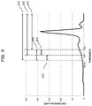
- FIG. 9 is a reference diagram explicitly illustrating energy ranges on the pulse height spectrum of FIG. 7 ;
- FIG. 10 is another flowchart to acquire the pulse height spectrum of the PCCT scanner relating to the first embodiment of the present invention.
- FIG. 11 is a block diagram showing a schematic configuration of the signal processor of the X-ray detector relating to a second embodiment of the present invention.
- the pulse height spectrum acquisition device relating to the present invention is to acquire pulse height spectra of a radiation detector having a plurality of counting units, each counting a detected signal of incoming X-rays, when the detected signal being equal to or larger than thresholds, and to output count values.
- the pulse height spectrum acquisition device includes a threshold setter configured to set to a first counting unit, a first threshold V1 as a threshold for a first measurement, along with setting to a second counting unit, a second threshold V2 larger than the first threshold V1, and to set to the first counting unit a reconfigured first threshold V1′ as the threshold for a second measurement, the reconfigured first threshold being different from the first threshold V1, a measurement controller configured to perform the first measurement and the second measurement, and a pulse height spectrum generator configured to generate the pulse height spectrum for the first threshold V1 of the first counting unit, on the basis of a difference between the count value from the first counting unit and the second counting unit obtained by the first measurement performed by the measurement controller, and the count value from the first counting unit and the second counting unit obtained by the second measurement.
- a threshold setter configured to set to a first counting unit, a first threshold V1 as a threshold for a first measurement, along with setting to a second counting unit, a second threshold V2 larger than the first threshold V1, and to set to the
- an X-ray CT scanner in particular, a PCCT scanner will be described with reference to the accompanying drawings.
- the PCCT scanner is provided with an imaging system including an X-ray source 120 , an X-ray detector 150 , a gantry rotor 110 placing the X-ray source 120 and the X-ray detector 150 in a manner opposed to each other and rotating about a predetermined rotation axis, a table 140 , a controller 170 for processing signals acquired by the X-ray detector 150 along with controlling the operations of the imaging system, and a computer 180 for creating reconstructed images on the basis of the data obtained by the X-ray detector 150 .
- an imaging system including an X-ray source 120 , an X-ray detector 150 , a gantry rotor 110 placing the X-ray source 120 and the X-ray detector 150 in a manner opposed to each other and rotating about a predetermined rotation axis, a table 140 , a controller 170 for processing signals acquired by the X-ray detector 150 along with controlling the operations of the imaging system, and a computer 180 for creating reconstructed images on the basis of the data
- an X-ray tube can be employed as the X-ray source 120 .
- the X-ray source 120 allows electron beams accelerated by tube voltage to hit a target material such as tungsten and molybdenum, to generate X-rays from the hit position (focal point), thereby emitting X-ray photons.
- a filter 125 is provided in proximity to the X-ray source 120 . The filter 125 adjusts a flux of the X-ray photons 130 and an energy distribution thereof, which are emitted from the X-ray source 120 .
- the X-ray source 120 and the X-ray detector 150 are placed in a manner opposed to each other, and the gantry rotor rotates about a predetermined rotation axis.
- the table 140 and the gantry rotor 110 are movable in predetermined directions relatively.
- CT scanners acquire data from all the directions, and the gantry rotor 110 rotates at a predetermined speed, allowing the X-ray source 120 and the X-ray detector 150 to rotate around the object 200 , so as to acquire data.
- the rotation speed is approximately one to four revolutions per second.
- the time required to accumulate data for acquiring projection data (one view) from one direction is typically on the order of 0.1 to 1 milliseconds.
- the X-ray detector 150 is provided with a detection unit 151 configured to detect the X-ray photons entering the X-ray detector 150 , and to output detected signals in response to energy of thus detected X-ray photons, and a signal processor 152 configured to collect and process the detected signals output from the detection unit 151 .
- the detected signals of the X-ray photons output from the detection unit 151 are subjected to pulse-mode processing by more than one signal processors 152 , and then counted.
- the term “counting” described here may include a meaning to acquire energy information, in addition to counting the detected X-ray photons.
- Detection of X-rays having been scattered by the object 200 may generate undesirable signals, and therefore, preferably, a collimator 145 is placed in front of the detection unit 151 when viewed from the X-ray source 120 side, so as to block the scattered X-rays. Details of the X-ray detector 150 will be described below.
- the controller 170 controls the gantry rotor 110 , the X-ray source 120 , the table 140 , the X-ray detector 150 , and other components, performs predetermined processing on the signals that are detected and collected by the X-ray detector 150 , and transfers the processed signals to the computer 180 .
- the computer 180 is provided with a CPU 181 and a storage unit 182 . Also as shown in FIG. 2 , the CPU 181 implements functions of the threshold setter 184 , the measurement controller 185 , and the pulse height spectrum generator 186 .
- the computer 180 stores in the storage unit 182 , the signals acquired via the controller 170 from the signal processor 152 of the X-ray detector 150 , and on the basis of those signals and other data, the computer reconstructs tomographic images of the subject and reconstructed images are created.
- the threshold setter 184 provides thresholds respectively in the plurality of counting units 351 to 354 (see FIG. 6 ) held by a channel 165 of a sub-pixel 21 of the detector, which will be described below. Details of the threshold setting according to the threshold setter 184 will be described later.
- the measurement controller 185 generates control signals to perform measurement (imaging) of the object, further generates control signals to perform necessary measurements to generate a pulse height spectrum, and then outputs those control signals to the controller 170 .
- the pulse height spectrum generator 186 receives via the controller 170 the outputs from the detector, obtained by the measurement performed based on the control signals for the measurement generated by the measurement controller 185 , and generates the pulse height spectrum on the basis of the outputs thus received.
- the computer 180 is connected to a display unit 191 and to an input unit 192 , and the reconstructed images created by the CPU 181 functioning as the image generator (not illustrated) are displayed on the display unit 191 , according to the instruction from the CPU 181 .
- the input unit 192 accepts entries of imaging conditions and other information for the X-ray CT scanner, i.e., parameters necessary for data collection, such as a value of voltage applied to the X-ray source 120 from a high-voltage source (not illustrated) and tube current, and velocity and other values of the rotating operation of the X-ray source 120 .
- the display unit 191 is capable of displaying the parameters and the values thereof, and soon, input from the input unit 192 .
- a part or all of the controller 170 and the computer 180 may be constructed as a system containing a memory and a main storage, and functions of the components constituting the controller 170 and the computer 180 can be implemented by the CPU that loads programs into the memory, the programs being stored in advance in the storage unit, and then executing the programs.
- a part or all of the functions may also be configured by hardware such as ASIC (Application Specific Integrated Circuit) and FPGA (Field Programmable Gate Array).
- the X-ray detector 150 is provided with a detection unit 151 comprising a two-dimensional array of multiple pixels 20 and detecting X-ray photons per pixel to output signals, and a signal processor 152 configured to collect and process the signals output from each of the pixels 20 of the detection unit 151 .
- the detection unit 151 is one of the units of the X-ray detector 150 , and comprises an array of multiple pixels 20 for detecting incoming X-ray photons.
- the X-ray photons 130 passing through the object 200 enter each of the pixels 20 , and the X-ray photons are counted.
- the number of the pixels included in the detection unit 151 may be 892 in the longitudinal direction and 64 in the transverse direction.
- the detection unit 151 is provided in the form of arc, setting the X-ray source 120 as the arc-center approximately, and along with the rotation of the gantry rotor 110 , the detection unit 151 rotates with keeping the positional relation with the X-ray source 120 .
- the arrangement of the pixels 20 in the example as shown in FIG. 3 are depicted in a manner that forms an approximate curved surface. However, in many cases, the pixels may form a flat surface without curvature, and sometimes, the arrangement of the pixels 20 in the detection unit 151 may form a polygonal shape.
- the X-ray photons passing through the object 200 enter each of the pixels 20 , and they are counted.
- the collimator 145 (see FIG. 1 ) is placed on the pixels 20 , on the X-ray source 120 side.
- the collimator 145 may be a two-dimensional square hole collimator, having the same pitch and shape as the pixels 20 , or it may be one-dimensional slit collimator.
- each of the pixels 20 comprises a group of sensing elements referred to as sub-pixels 21 , where a plurality of sensing elements are provided in an array.
- This group of sensing elements constitutes the pixel 20 serving as one unit of the X-ray detector 150 .
- one pixel 20 has a configuration divided into multiple sub-pixels 21 . This configuration allows reduction of the count rate per processing circuit.
- the sub-pixels 21 included in the pixel 20 are sensing elements in a mode of, what is called, photon counting, and they detect incoming X-ray photons, and count the X-ray photons, with separating them into four energy ranges, for instance, in the signal processor 152 being connected.
- FIG. 4 illustrates the pixels 20 where multiple sensing elements 21 each having the same size, are provided in the array with two elements in the channel direction and two elements in the slice direction, that is, four elements in total.
- the size of the pixel 20 is one millimeter square and the size of each sub-pixel is 0.5 millimeter square, for instance. Following description of the present embodiment will be given, assuming that the pixel 20 comprises four sub-pixels 21 .
- the size of the pixel 20 is one millimeter square, and each pixel is divided into four sub-pixels with 0.5 millimeter square each.
- Other division patterns may be available variously, such as nine sub-pixels of 3 ⁇ 3, or 16 sub-pixels of 4 ⁇ 4.
- the vertical and horizontal directions may have different division numbers, like n ⁇ m (n and m are natural numbers).
- the sub-pixels thus divided are not necessarily the same in size, and the present invention is applicable to the case where the pixel is divided into sub-pixels various in size. It is to be noted that the present invention is applicable to the case where the pixel is not divided into the sub-pixels. In this case, the “sub-pixel” in the following description will be read as “pixel”.
- each of the sensing elements 21 constituting each pixel 20 has a structure provided with positive and negative electrodes 41 and 42 in a manner placing a detection layer 40 therebetween, and the signal processor 152 is connected to each of the electrodes 41 and 42 .
- the negative electrode 41 hereinafter, referred to as “common electrode 41 ”
- the common electrode 41 provided on the entrance surface of the X-ray photons 130 (the upper surface of the detection layer 40 in FIG. 5 ) serves as the common electrode covering the pixels 20 entirely.
- the positive electrode 42 (hereinafter, referred to as “individual electrode 42 ”) is provided for each sensing element 21 serving as the sub-pixel, and individual channels 165 of the signal processor 152 are connected to the individual electrodes 42 respectively.
- signals are read per sub-pixel, thereby counting the X-ray photons including acquisition of energy information.
- the pixels 20 are provided with one common electrode 41 and the individual electrodes 42 the number of which corresponds to the number of the sub-pixels 21 (sensing elements).
- the pixel 20 includes multiple individual electrodes 42 on the surface of the detection layer 40 , and as indicated by broken lines in FIG. 5 , a region associated with one individual electrode 42 forms one sub-pixel 21 .
- a radiation detector material of a direct conversion type is used as the detection layer 40 , boundaries between sub-pixels 21 (see FIG. 4 ) may be invisible physically when viewed from the top of the pixel 20 , but the detection layer is divided into the sub-pixels, to function as the radiation detector.
- a compound semiconductor being a radiation detector material of a direct conversion type, which is easy to micro machining and capable of direct reading of electrical signals, such as Cadmium Telluride, Cadmium Zinc Telluride, Thallium Bromide, Mercury Iodide, and Bismuth Iodide.
- a scintillator a radiation detector material of a indirect conversion type optically coupled with an optical device may be used as the detection layer.
- the thickness of the detection layer is around 0.5 mm to 3 mm.
- the X-ray photons 130 enter the detection layer 40 from the common electrode 41 side, then the X-ray photons being detected, and an electrical charge whose amount is responsive to the energy of thus detected X-ray photons is generated.
- the high-voltage power source applies voltage of ⁇ 600 V to the common electrode 41 , for instance. It is desirable that there should be no attenuation of X-ray photons by the common electrode 41 or by the individual electrodes 42 .
- the common electrode 41 and the individual electrodes 42 should be sufficiently thinner than the detection layer 40 , and they may be processed to 1 ⁇ m or less in thickness.
- the signal processor 152 is provided with channels 165 respectively for sub-pixels 21 , and the channels 165 detect output signals from the sub-pixels 21 belonging to the pixel 20 . Then, a signal adder adds up the signals according to predetermined conditions, collects the signals as an output signal from each pixel 20 , and processes thus obtained output signal.
- FIG. 6 illustrates an example of the channels 165 of the signal processor 152 , being connected to the sub-pixels 21 , respectively.
- Each of the channels 165 is provided with a charge sensitive pre-amplifier 310 configured to convert the X-ray photons detected as charge signals into voltage signals, a shaping amplifier 320 configured to perform shaping of the voltage signals converted by the charge sensitive pre-amplifier 310 , and four counting units 351 to 354 to obtain energy information by comparing the voltage related to the voltage signal and thresholds (reference voltages).
- the counting units 351 to 354 are provided with converters 331 to 334 , and counters 341 to 344 , respectively.
- Signal processing in the channel 165 as thus configured is performed as the following.
- a signal read out from any of the sub-pixels in the pixel 20 is initially converted into a voltage signal from a charge signal, by the charge sensitive pre-amplifier 310 , and output to the shaping amplifier 320 .
- the voltage signal converted by the charge sensitive pre-amplifier 310 is subjected to shaping in the shaping amplifier 320 (hereinafter, the voltage signal after the shaping will be referred to as “detected signal”), and in order to obtain the energy information, signals having a pulse height equal to or larger than thresholds (reference voltages) are counted in the counting units 351 to 354 .
- comparators 331 to 334 are provided to obtain the energy information, and thresholds V1 to V4, different from one another are given to the comparators, respectively. Then, in the comparators 331 to 334 , the detected signal is compared with the thresholds V1 to V4. When the detected signal is larger than the threshold, any of the counters 341 to 344 corresponding to the comparator is incremented.
- the X-ray photons can be categorized into four types and counted separately, in response to the energy amount.
- the individual channels 165 in the signal processor 152 are reset to become ready for the counting of next event.
- incrementing is stopped, and the count rate of each counter is output to the controller 170 .
- any number of the comparators at least two, may be employed.
- the thresholds V1 to V4 given to the comparators 331 to 334 respectively are able to supply the same voltage to a plurality of sub-pixels.
- the same threshold may be associated with a different energy amount, as to each counting unit.
- the same count results may not be obtained in some cases, as to each of the counting unit (even though impact of statistical errors is excluded). In such a case, it is preferable to perform calibration for each counting unit.
- X-rays or gamma-rays having characteristic energy is made to enter, and a pulse height spectrum is obtained in response to each threshold setting.
- the X-rays or gamma-rays having characteristic energy may include line gamma-ray or characteristic X-ray, specifically, gamma-rays of 60 keV emitted from 241 Am, gamma-rays of 122 keV emitted from 57 Co, characteristic X-rays of 31 and 35 keV emitted from 133 Ba, and characteristic X-rays of 75 keV and 85 keV emitted from lead irradiated with radiation.
- the characteristic energy such as Compton edge or a back scattering peak of such line gamma-ray or characteristic X-ray, and maximum energy of the X-ray photons determined by the tube voltage applied to the X-ray tube.
- the characteristic energy held by the incident X-rays or gamma-rays is not ignorable, it is preferable to render the characteristic energy held by the incident X-rays or gamma-rays to fall into the range, as close as possible to the energy range that is targeted for calibration.
- FIG. 7 shows an example of the pulse height spectrum that is obtained with the entry of gamma-rays from 57 Co. According to the pulse height spectrum as shown in FIG. 7 , it can be read that the photo peak of 122 keV is associated with the threshold setting to 47 . If it is known that 60 keV is associated with the threshold setting to 23 in another measurement, it is found according to interpolation therebetween, that the threshold can be set to 31 for the counting an event of 80 keV or larger, whereby calibration of the counting units 351 to 354 can be achieved.
- the pulse height spectrum of the whole energy range (or the whole threshold range), but it may be acquired as to a range only in proximity to the characteristic energy of incident X-rays or gamma-rays.
- the pulse height spectrum is acquired only within the range where the threshold setting is from 40 to 55 , it is possible to obtain what value of the threshold setting is associated with the photo peak of 122 keV.
- the pulse height spectrum generator 186 generates the pulse height spectrum for each of the counting units 351 to 354 .
- first counting unit 351 the pulse height spectrum generated for the counting unit 351
- second counting unit 352 the count rate (count value) of the counting unit 352 adjacent to the first counting unit 351 is also utilized.
- the pulse height spectrum is generated and acquired according to the flowchart of FIG. 8 .
- step S 11 the threshold setter 184 sets the threshold V1 to the first counting unit 351 , and in step S 12 , sets the threshold V2 to the second counting unit 352 .
- the threshold setter 184 sets the first threshold V1 to the first counting unit, and sets to the second counting unit, the second threshold V2 that is larger than the first threshold V1.
- the measurement controller 185 generates a control signal used to perform COUNT A, and outputs the control signal to the controller 170 .
- the controller 170 controls the gantry rotor 110 , the X-ray source 120 , the table 140 , the X-ray detector 150 , and other components, according to the control signal from the measurement controller 185 , and performs COUNT A.
- the threshold setter 184 reconfigures the first threshold of the first counting unit. That is, the threshold setter 184 performs reconfiguration to change the first threshold V1 of the first counting unit to the first threshold V1′, to be used as the threshold for the measurement (COUNT) B. The threshold setter 184 performs this reconfiguration so that the first threshold V1′ becomes a value smaller than the second threshold V2 and different from the first threshold V1, and leaves the second threshold V2 as it is.
- the measurement controller 185 generates a control signal to perform COUNT B, and outputs the control signal to the controller 170 .
- the controller 170 performs COUNT B according to the control signal from the measurement controller 185 .
- step S 16 the pulse height spectrum generator 186 generates a pulse height spectrum for the first threshold in the first counting unit 351 , on the basis of a difference between the count rate from the first counting unit and the second counting unit obtained by COUNT A, and the count rate from the first counting unit and the second counting unit obtained by COUNT B.
- the pulse height spectrum c1 (V1 n ) at the threshold V1 n is obtained according to the following process.
- the measurement controller 185 employs the threshold V2 m , where V2 m >V1 n for the second counting unit 352 that is connected to the same sub-pixel to which the first counting unit 351 is connected, and performs COUNT A and B with the following settings:
- the pulse height spectrum c1 (V1 n ) is obtained according to the following Equation 2. This corresponds to obtaining of the pulse height spectrum that is associated with the energy range 400 , as shown in FIG. 9 , using a difference between the count rate associated with the energy range 440 and the count rate associated with the energy range 450 .
- Ctot denotes a total count rate (total number of counts per unit time), and Ctot is the same value irrespective of the counting units 351 to 354 , in each of the channels 165 of one signal processor 152 .
- C1 denotes the count rate obtained in the counting unit 351
- c1 denotes the pulse height spectrum of the counting unit 351 . The count rate is obtained by normalizing the count value by the measuring time.
- step 17 thus obtained pulse height spectrum is stored in the storage unit 182 .
- step S 18 it is determined whether the pulse height spectrum covering a targeted range is obtained. If it is determined it has not been obtained yet, the process proceeds with step S 19 to reconfigure the first threshold, and processing from steps S 12 to S 18 is repeated.
- step S 18 the process for acquiring the pulse height spectrum is completed.
- the pulse height spectrum is obtained according to the following Equation 3 in the conventional method as disclosed in the aforementioned Patent Literature 1.
- Ctot denotes the total count rate (the total number of counts per unit time), and the value of Ctot is the same, irrespective of the counting units 351 to 354 , in each of the channels 165 of in one signal processor 152 .
- This corresponds to obtaining of the pulse height spectrum that is associated with the energy range 400 , as shown in FIG. 9 , by using a difference between the count rate associated with the energy range 410 and the count rate associated with the energy range 420 .
- C1 denotes the count rate obtained in the counting unit 351
- c1 denotes the pulse height spectrum of the counting unit 351 .
- the count rate is obtained by normalizing the count value by the measuring time.
- the measuring time can be reduced according to the method of the present embodiment for generating the pulse height spectrum.
- the count rate C1(V1 n ⁇ 1 ) (associated with the energy range 410 in FIG. 9 ) is 100 cps when the threshold of the counting unit 351 is set to V1 n ⁇ 1
- the count rate C1(V1 n ) (associated with the energy range 420 in FIG. 9 ) is 90 cps when this threshold is set to V1 n
- the count rate C2(V2 m ) associated with the energy range 430 in FIG. 9 ) is 80 cps when the threshold of the counting unit 352 is set to V2 m .
- an expected value of the pulse height spectrum c1(V1 n ) for the energy range 400 becomes 10 counts according to both the conventional method and the present embodiment.
- a degree of accuracy of c1(V1 e ) is calculated as the following, according to the Poisson distribution.
- the accuracy in measurement is proportional to the square of the measuring time, and therefore, it is found that only one-six or less measuring time is required to achieve the same level of accuracy.
- V2 m Assuming that C1(V1 n ⁇ 1 ) is approximately equal to C1(V1 n ), it is preferable to set V2 m so that C2 (V2 m ) is equal to or larger than a half of C1(V1 n ) (to set V2 m to be a value close to V1 n ).
- the measuring time may be provided to different thresholds independently. Under the condition that the pulse height spectrum is given accuracy being required, necessary measuring time can be obtained in response to the count rates C1(V1) and C2(V2), or in response to a difference therebetween. This is preferable since the total measuring time can be reduced, by setting the measuring time flexibly depending on the values of the thresholds.
- the counting is required to be normalized based on live time (the time obtained by subtracting dead time in measurement system, from the actual measuring time), not based on the actual measuring time.
- live time the time obtained by subtracting dead time in measurement system, from the actual measuring time
- V2 m the same value of V2 m is provided to multiple V n as to which the pulse height spectrum is required to obtain, thereby lessening the number of measurements to reduce the measuring time.
- V1, V2 (V1 n ⁇ 2 , V2 m ), (V1 n ⁇ 1 , V2 m ), and (V1 n , V2 m )
- the measurement can be performed three times.
- two pulse height spectra c1(V1 n ⁇ 1 ) and c1(V1 n ) respectively associated with V1 n ⁇ 1 and V1 n can be obtained according to the measurement of three times, and this may prevent increase of the number of measurements.
- the pulse height spectrum of each counting unit As described above, it is necessary to obtain the pulse height spectrum of each counting unit.
- the method for acquiring the pulse height spectrum of the counting unit 351 According to the same procedures as described in the aforementioned method, the pulse height spectrum can be obtained for other counting units within a short amount of time.
- four counting units are respectively provided with the thresholds V1 to V4 and the measurements are performed, so as to obtain the pulse height spectra.
- step S 21 the threshold setter 184 sets the thresholds V1 to V4, different from one another, respectively to the first to the fourth counting units 351 to 354 .
- step S 22 the measurement controller 185 generates a control signal to perform COUNT A, and outputs the control signal to the controller 170 .
- the controller 170 controls the gantry rotor 110 , the X-ray source 120 , the table 140 , the X-ray detector 150 , and other components, and performs COUNT A.
- step S 23 the threshold setter 184 increases the threshold V1 of the first counting unit 351 and the threshold V3 of the third counting unit 353 to reconfigure the thresholds as the next values.
- the measurement controller 185 performs COUNT B in step S 24 .
- step S 25 the pulse height spectra are acquired from the count rate obtained by COUNT A and COUNT B, and the storage unit 182 stores thus acquired pulse height spectra (step S 26 ). It is determined whether or not thus acquired pulse height spectra cover target ranges. On the other hand, when it is determined that such pulse height spectra have not been acquired yet, the process proceeds with step S 28 . When it is determined that the pulse height spectra covering the target ranges have been obtained in step S 27 , the process for acquiring the pulse height spectra is completed.
- step S 28 the threshold V2 of the second counting unit 352 is increased and reconfigured as the next value. At this time, the threshold V4 of the fourth counting unit 354 may also be increased as needed.
- step S 29 according to the threshold set in step S 28 , COUNT A′ is performed.
- step S 30 the pulse height spectrum generator 186 generates the pulse height spectrum on the basis of the count rate obtained from the latest two measurements, and the storage unit 182 stores the pulse height spectrum generated in step S 31 .
- next step S 32 it is determined whether or not the pulse height spectrum covering the target range is obtained, and if it is determined that such pulse height spectrum has not been acquired, the process proceeds with step S 23 , and the processing from steps S 23 to S 32 is repeated. When it is determined that the pulse height spectra covering the target ranges have been obtained in step S 27 or S 32 , the process for acquiring the pulse height spectra is completed.
- the pulse height spectra calculation process in steps S 25 and S 30 is performed according to the following Equation 5, from the count rate C each obtained from the measurements (COUNTs) described above.
- the pulse height spectra of the first counting unit 351 to the third counting unit 353 can be obtained efficiently.
- the pulse height spectrum may be obtained from the measurement using the aforementioned method separately.
- c 1( V 1 n ) ( C 1 COUNTA ( V 1 n ⁇ 1 ) ⁇ C 2 COUNTA ( V 2 m-1 )) ⁇ ( C 1 COUNTB ( V 1 n ) ⁇ C 2 COUNTB ( V 2 m-1 ))
- c 1( v 1 n+1 ) ( C 1 COUNTA′ ( V 1 n ) ⁇ C 2 COUNTA′ ( V 2 m )) ⁇ ( C 1 COUNTB′ ( V 1 n+1 ) ⁇ C 2 COUNTB′ ( V 2 m ))
- c 2( V 2 m ) ( C 2 COUNTB ( V 2 m-1 ) ⁇ C 3 COUNTB ( V 3 p )) ⁇ ( C 2 COUNTA′ ( V 2 m ) ⁇ C 3 COUNTA′ ( V 3 p ))
- c 3( V 3 p ) ( C 3 COUNTA ( V 3 p ⁇ 1 ) ⁇ C 4 COUNTA ( V 4 q ⁇ 1
- the threshold V4 of the counting unit 354 is not necessarily incremented by one, such as V q ⁇ 1 , V q , and V q+1 .
- the threshold V4 can be a value sufficiently larger value than the value of V3, it is desirable to vary the value of the threshold V4 gradually following the variation of V3 as given by the aforementioned Equation, in light of an objective of the present embodiment, i.e., “to reduce the measuring time by mitigating errors with narrowing the energy range 450 ”.
- the simple configuration is provided as shown in FIG. 6 , holding less number of parameters, such as four thresholds for four counting units, and generating a highly accurate pulse height spectra in a short amount of time with calibration of the detector, whereby the radiation detector or the radiation imaging apparatus can be implemented at low cost.
- FIG. 11 illustrates an example of an individual channel 1165 connected to each sub-pixel of the signal processor 152 .
- a signal output from the shaping amplifier 320 is counted in response to a result of comparison of the pulse height, larger or smaller than a threshold (reference voltage), in each of the counting units 1351 to 1354 .
- the counting unit 1351 there are counted a signal having the pulse height between the threshold V1 and V2, in the counting unit 1352 , a signal having the pulse height between the thresholds V2 and V3, in the counting unit 1353 , a signal having the pulse height between the threshold V3 and V4, and in the counting unit 1354 , a signal having the pulse height equal to or larger than the threshold V4.
- the thresholds are configured in a manner that satisfies V1 ⁇ V2 ⁇ V3 ⁇ V4.
- the signal when the pulse height is between the threshold V2 and V3, the signal is output from the comparators 331 and 332 , but not from the comparators 333 and 334 . Since there is an entry of the signal in the counter 1341 , coming from both of the comparators 331 and 332 , it can be determined that the original signal does not have the pulse height between the thresholds V1 and V2, and this event is not counted in the counter 1341 .
- D1 denote the count rate obtained in the counting unit 1351 , and this value is related to the count rate obtained in the configuration of the first embodiment, as given in the following:
- the threshold V2 m satisfying V2 m >V1 n is employed, similar to the first embodiment, and the measurement (COUNT) is performed with the settings as the following:
- a difference between the counting results obtained in the two counting units may be calculated and output in the controller 170 , unlike the second embodiment where the outputs from the two comparators are input in one counter, and this enables implementation of the same function as the second embodiment.
- the value of n is made to vary, one by one, to obtain the pulse height spectrum, but modification is possible such as varying the value of n, two by two, depending on how much density is required in obtaining the pulse height spectrum.
- the sub-pixels are separated, by providing the common electrode on the upper surface of the radiation detector material of a direct conversion type, with the individual electrodes on the lower side thereof.
- the sub-pixels may be provided with the individual electrodes also on the upper surface, without using the common electrode.
- the pixels 20 in the radiation detectors adjacent to each other may share the common electrode on the upper surface, or may be provided with the electrodes individually.
- the detector As a material of the detector, it is also possible to employ a material comprising a scintillator (radiation detector material of an indirect conversion type) optically coupled with an optical device, instead of the radiation detector material of a direct conversion type.
- the scintillator covered with a light-shielding agent may be provided for each sub-pixel.
- a method for producing micro-cracks between sub-pixels by laser may be used to separate the sub-pixels.
- a photomultiplier tube (PMT), photodiode (PD), avalanche photodiode (APD), silicone photomultiplier (SiPM), and similar elements may be employed.
- CPU 182 . . . storage unit, 184 . . . threshold setter, 185 . . . measurement controller, 186 . . . pulse height spectrum generator, 191 . . . display unit, 192 . . . input unit
Landscapes
- Health & Medical Sciences (AREA)
- Life Sciences & Earth Sciences (AREA)
- Engineering & Computer Science (AREA)
- Medical Informatics (AREA)
- Physics & Mathematics (AREA)
- Molecular Biology (AREA)
- High Energy & Nuclear Physics (AREA)
- Heart & Thoracic Surgery (AREA)
- General Health & Medical Sciences (AREA)
- Pathology (AREA)
- Radiology & Medical Imaging (AREA)
- Biomedical Technology (AREA)
- Nuclear Medicine, Radiotherapy & Molecular Imaging (AREA)
- Biophysics (AREA)
- Surgery (AREA)
- Animal Behavior & Ethology (AREA)
- Optics & Photonics (AREA)
- Public Health (AREA)
- Veterinary Medicine (AREA)
- Spectroscopy & Molecular Physics (AREA)
- General Physics & Mathematics (AREA)
- Pulmonology (AREA)
- Theoretical Computer Science (AREA)
- Measurement Of Radiation (AREA)
- Apparatus For Radiation Diagnosis (AREA)
Abstract
Description
c(V n)=C(V n−1)−C(V n) (1)
- COUNT A: (V1, V2)=(V1n−1, V2m)
- COUNT B: (V1, V2)=(V1n, V2m)
√{square root over (100+90)}=13.8 COUNT Conventional Method
√{square root over ((100−80)+(90−80))}=5.5 COUNT Present Embodiment
- COUNT A: (V1, V2, V3, V4)=(V1n−1, V2m-1, V3p−1, V4q−1)
- COUNT B: (V1, V2, V3, V4)=(V1n, V2m-1, V3p, V4q−1)
- COUNT A′: (V1, V2, V3, V4)=(V1n, V2m, V3p, V4q)
- COUNT B′: (V1, V2, V3, V4)=(V1n+1, V2m, V3p+1, V4q)
- . . .
- where V1<V2<V3<V4
c1(V1n)=(C1COUNTA(V1n−1)−C2COUNTA(V2m-1))−(C1COUNTB(V1n)−C2COUNTB(V2m-1))
c1(v1n+1)=(C1COUNTA′(V1n)−C2COUNTA′(V2m))−(C1COUNTB′(V1n+1)−C2COUNTB′(V2m))
c2(V2m)=(C2COUNTB(V2m-1)−C3COUNTB(V3p))−(C2COUNTA′(V2m)−C3COUNTA′(V3p))
c3(V3p)=(C3COUNTA(V3p−1)−C4COUNTA(V4q−1))−(C3COUNTB(V3p)−C4COUNTB(V4q−1))
c3(V3p+1)=(C3COUNTA′(V3p)−C4COUNTA′(V4q))−(C3COUNTB′(V3p+1)−C4COUNTB′(V4q)) (5)
D1(V1,V2)=C1(V1)−C2(V2) (6)
- COUNT A: (V1, V2)=(V1n−1, V2m)
- COUNT B: (V1, V2)=(V1n, V2m) By using the count rate as obtained by the measurements, the pulse height spectrum c1 (V1n) can be obtained by the following Equation, and a similar effect can be achieved:
[8]
c1(V1n)=D1COUNTA(V1n−1 ,V2m)−D1COUNTB(V1n ,V2m) (7)
Claims (7)
Applications Claiming Priority (4)
| Application Number | Priority Date | Filing Date | Title |
|---|---|---|---|
| JP2017141057A JP6912304B2 (en) | 2017-07-20 | 2017-07-20 | Wave frequency distribution acquisition device, wave frequency distribution acquisition method, wave frequency distribution acquisition program and radiation imaging device |
| JPJP2017-141057 | 2017-07-20 | ||
| JP2017-141057 | 2017-07-20 | ||
| PCT/JP2018/019814 WO2019017069A1 (en) | 2017-07-20 | 2018-05-23 | Device for acquiring wave height frequency distribution, method for acquiring wave height frequency distribution, program for acquiring wave height frequency distribution, and radiation image capturing device |
Publications (2)
| Publication Number | Publication Date |
|---|---|
| US20200170586A1 US20200170586A1 (en) | 2020-06-04 |
| US11045153B2 true US11045153B2 (en) | 2021-06-29 |
Family
ID=65016131
Family Applications (1)
| Application Number | Title | Priority Date | Filing Date |
|---|---|---|---|
| US16/628,253 Active US11045153B2 (en) | 2017-07-20 | 2018-05-23 | Device for acquiring pulse height spectrum, method for acquiring pulse height spectrum, program for acquiring pulse height spectrum, and radiation imaging apparatus |
Country Status (3)
| Country | Link |
|---|---|
| US (1) | US11045153B2 (en) |
| JP (1) | JP6912304B2 (en) |
| WO (1) | WO2019017069A1 (en) |
Cited By (3)
| Publication number | Priority date | Publication date | Assignee | Title |
|---|---|---|---|---|
| US11779296B2 (en) * | 2020-03-20 | 2023-10-10 | Canon Medical Systems Corporation | Photon counting detector based edge reference detector design and calibration method for small pixelated photon counting CT apparatus |
| US20240036219A1 (en) * | 2020-12-09 | 2024-02-01 | Ams International Ag | Electric circuitry for baseline extraction in a photon counting system |
| US12372678B2 (en) | 2021-03-12 | 2025-07-29 | Job Corporation | Calibration device and calibration method for detector |
Families Citing this family (3)
| Publication number | Priority date | Publication date | Assignee | Title |
|---|---|---|---|---|
| EP3942337B1 (en) * | 2019-03-22 | 2026-03-04 | Southern Innovation International Pty Ltd | Radiation detection with non-parametric decompounding of pulse pile-up |
| JP2023076345A (en) * | 2021-11-22 | 2023-06-01 | ソニーセミコンダクタソリューションズ株式会社 | Photodetector, imaging device and ranging device |
| CN116340807B (en) * | 2023-01-10 | 2024-02-13 | 中国人民解放军国防科技大学 | Broadband Spectrum Signal Detection and Classification Network |
Citations (8)
| Publication number | Priority date | Publication date | Assignee | Title |
|---|---|---|---|---|
| JP2007256096A (en) | 2006-03-23 | 2007-10-04 | Hamamatsu Photonics Kk | Radiation detector and radiation detection method |
| WO2011039819A1 (en) | 2009-10-01 | 2011-04-07 | 株式会社島津製作所 | Pulse-height analyzer and nuclear medicine diagnosis device provided with same |
| US20120268105A1 (en) | 2011-04-21 | 2012-10-25 | Toshiba Medical Systems Corporation | Apparatus for analog-to-digital conversion with a high effective-sample-rate on the leading edge of a signal pulse |
| WO2015087663A1 (en) | 2013-12-09 | 2015-06-18 | 浜松ホトニクス株式会社 | Two-dimensional photon counting element |
| US20150185332A1 (en) | 2012-06-27 | 2015-07-02 | Koninklijke Philips N.V. | Spectral photon counting detector |
| US20150192681A1 (en) | 2014-01-07 | 2015-07-09 | Samsung Electronics Co., Ltd. | Radiation detector, tomography imaging apparatus thereof, and radiation detecting apparatus thereof |
| JP2015184119A (en) | 2014-03-24 | 2015-10-22 | 株式会社東芝 | Device and program for measuring radioactivity |
| US10383585B2 (en) * | 2014-09-17 | 2019-08-20 | Hitachi, Ltd. | X-ray imaging apparatus |
-
2017
- 2017-07-20 JP JP2017141057A patent/JP6912304B2/en active Active
-
2018
- 2018-05-23 US US16/628,253 patent/US11045153B2/en active Active
- 2018-05-23 WO PCT/JP2018/019814 patent/WO2019017069A1/en not_active Ceased
Patent Citations (14)
| Publication number | Priority date | Publication date | Assignee | Title |
|---|---|---|---|---|
| JP2007256096A (en) | 2006-03-23 | 2007-10-04 | Hamamatsu Photonics Kk | Radiation detector and radiation detection method |
| US20090140159A1 (en) | 2006-03-23 | 2009-06-04 | Hamamatsu Photonics K.K. | Radiation detector and radiation detecting method |
| WO2011039819A1 (en) | 2009-10-01 | 2011-04-07 | 株式会社島津製作所 | Pulse-height analyzer and nuclear medicine diagnosis device provided with same |
| US20120184848A1 (en) | 2009-10-01 | 2012-07-19 | Junichi Ohi | Pulse height analyzer and nuclear medicine diagnosis apparatus provided with the same |
| US20120268105A1 (en) | 2011-04-21 | 2012-10-25 | Toshiba Medical Systems Corporation | Apparatus for analog-to-digital conversion with a high effective-sample-rate on the leading edge of a signal pulse |
| JP2012225923A (en) | 2011-04-21 | 2012-11-15 | Toshiba Corp | Electronic device and output method |
| JP2015528901A (en) | 2012-06-27 | 2015-10-01 | コーニンクレッカ フィリップス エヌ ヴェ | Spectral photon counting detector |
| US20150185332A1 (en) | 2012-06-27 | 2015-07-02 | Koninklijke Philips N.V. | Spectral photon counting detector |
| WO2015087663A1 (en) | 2013-12-09 | 2015-06-18 | 浜松ホトニクス株式会社 | Two-dimensional photon counting element |
| US20160305818A1 (en) | 2013-12-09 | 2016-10-20 | Hamamatsu Photonics K.K. | Two-dimensional photon counting element |
| US20150192681A1 (en) | 2014-01-07 | 2015-07-09 | Samsung Electronics Co., Ltd. | Radiation detector, tomography imaging apparatus thereof, and radiation detecting apparatus thereof |
| JP2015184119A (en) | 2014-03-24 | 2015-10-22 | 株式会社東芝 | Device and program for measuring radioactivity |
| US20160370475A1 (en) | 2014-03-24 | 2016-12-22 | Kabushiki Kaisha Toshiba | Radiation measuring apparatus, computer program product, and radiation computed tomography apparatus |
| US10383585B2 (en) * | 2014-09-17 | 2019-08-20 | Hitachi, Ltd. | X-ray imaging apparatus |
Non-Patent Citations (2)
| Title |
|---|
| International Preliminary Report on Patentability issued in corresponding International Application No. PCT/JP2018/019814 dated Jan. 30, 2020. |
| International Search Report with English translation and Written Opinion issued in corresponding application No. PCT/JP2018/019814 dated Aug. 14, 2018. |
Cited By (3)
| Publication number | Priority date | Publication date | Assignee | Title |
|---|---|---|---|---|
| US11779296B2 (en) * | 2020-03-20 | 2023-10-10 | Canon Medical Systems Corporation | Photon counting detector based edge reference detector design and calibration method for small pixelated photon counting CT apparatus |
| US20240036219A1 (en) * | 2020-12-09 | 2024-02-01 | Ams International Ag | Electric circuitry for baseline extraction in a photon counting system |
| US12372678B2 (en) | 2021-03-12 | 2025-07-29 | Job Corporation | Calibration device and calibration method for detector |
Also Published As
| Publication number | Publication date |
|---|---|
| JP2019020334A (en) | 2019-02-07 |
| WO2019017069A1 (en) | 2019-01-24 |
| JP6912304B2 (en) | 2021-08-04 |
| US20200170586A1 (en) | 2020-06-04 |
Similar Documents
| Publication | Publication Date | Title |
|---|---|---|
| US11045153B2 (en) | Device for acquiring pulse height spectrum, method for acquiring pulse height spectrum, program for acquiring pulse height spectrum, and radiation imaging apparatus | |
| US10292669B2 (en) | Radiation imaging apparatus, radiation counting apparatus, and radiation imaging method | |
| US9000385B2 (en) | Method and apparatus for acquiring radiation data | |
| US10064585B2 (en) | Photon detecting element, photon detecting device, and radiation analyzing device | |
| JP7820134B2 (en) | Photon counting X-ray CT device and method | |
| US10357214B2 (en) | Photon counting CT apparatus, light detection device, radiation detection device, and radiation analysis device | |
| US10219763B2 (en) | Photon counting CT device and estimated exposure level computation method | |
| JP5920930B2 (en) | Gamma camera, SPECT apparatus, PET apparatus, and gamma ray measurement image generation method | |
| US9877689B2 (en) | Detection device and data processing method | |
| CN102670232B (en) | Positron emission computed tomography device, and method executed through the same | |
| JP2021146190A (en) | Photon counting ct apparatus and method | |
| US9433391B2 (en) | Scintillator and radiation detection device | |
| US12102471B2 (en) | Iterative method for material decomposition calibration in a full size photon counting computed tomography system | |
| US10302779B2 (en) | Radiation detector, radiation imaging device, computer tomography device, and radiation detection method | |
| JP6518651B2 (en) | X-ray imaging device | |
| WO2018003918A1 (en) | Radiographic imaging device, radiographic imaging method, and radiographic imaging program | |
| JP2013007585A (en) | Positron emission computer tomographic imaging apparatus and x-ray ct (computed tomography) device | |
| US9933530B2 (en) | Photon detector, radiation analyzer, and computer program product | |
| CN113253330A (en) | Gamma ray radiation imaging device and energy calibration method |
Legal Events
| Date | Code | Title | Description |
|---|---|---|---|
| FEPP | Fee payment procedure |
Free format text: ENTITY STATUS SET TO UNDISCOUNTED (ORIGINAL EVENT CODE: BIG.); ENTITY STATUS OF PATENT OWNER: LARGE ENTITY |
|
| STPP | Information on status: patent application and granting procedure in general |
Free format text: NOTICE OF ALLOWANCE MAILED -- APPLICATION RECEIVED IN OFFICE OF PUBLICATIONS |
|
| STPP | Information on status: patent application and granting procedure in general |
Free format text: PUBLICATIONS -- ISSUE FEE PAYMENT RECEIVED |
|
| STPP | Information on status: patent application and granting procedure in general |
Free format text: PUBLICATIONS -- ISSUE FEE PAYMENT VERIFIED |
|
| STCF | Information on status: patent grant |
Free format text: PATENTED CASE |
|
| AS | Assignment |
Owner name: FUJIFILM HEALTHCARE CORPORATION, JAPAN Free format text: CORRECTIVE ASSIGNMENT TO CORRECT THE THE PROPERTY AND APPLICATION NUMBERS PREVIOUSLY RECORDED AT REEL: 058026 FRAME: 0559. ASSIGNOR(S) HEREBY CONFIRMS THE ASSIGNMENT;ASSIGNOR:HITACHI LTD.;REEL/FRAME:058917/0853 Effective date: 20211013 |
|
| AS | Assignment |
Owner name: FUJIFILM CORPORATION, JAPAN Free format text: MERGER;ASSIGNOR:FUJIFILM HEALTHCARE CORPORATION;REEL/FRAME:069170/0453 Effective date: 20240701 |
|
| MAFP | Maintenance fee payment |
Free format text: PAYMENT OF MAINTENANCE FEE, 4TH YEAR, LARGE ENTITY (ORIGINAL EVENT CODE: M1551); ENTITY STATUS OF PATENT OWNER: LARGE ENTITY Year of fee payment: 4 |
|
| AS | Assignment |
Owner name: FUJIFILM CORPORATION, JAPAN Free format text: MERGER;ASSIGNOR:FUJIFILM HEALTHCARE CORPORATION;REEL/FRAME:069869/0951 Effective date: 20240701 |