US11045019B2 - Quickly customizable systems that secure laptops to display tables and other display surfaces - Google Patents
Quickly customizable systems that secure laptops to display tables and other display surfaces Download PDFInfo
- Publication number
- US11045019B2 US11045019B2 US16/531,555 US201916531555A US11045019B2 US 11045019 B2 US11045019 B2 US 11045019B2 US 201916531555 A US201916531555 A US 201916531555A US 11045019 B2 US11045019 B2 US 11045019B2
- Authority
- US
- United States
- Prior art keywords
- laptop
- body portion
- lower body
- bottom support
- bracket
- Prior art date
- Legal status (The legal status is an assumption and is not a legal conclusion. Google has not performed a legal analysis and makes no representation as to the accuracy of the status listed.)
- Active, expires
Links
Images


Classifications
-
- A—HUMAN NECESSITIES
- A47—FURNITURE; DOMESTIC ARTICLES OR APPLIANCES; COFFEE MILLS; SPICE MILLS; SUCTION CLEANERS IN GENERAL
- A47F—SPECIAL FURNITURE, FITTINGS, OR ACCESSORIES FOR SHOPS, STOREHOUSES, BARS, RESTAURANTS OR THE LIKE; PAYING COUNTERS
- A47F7/00—Show stands, hangers, or shelves, adapted for particular articles or materials
-
- A—HUMAN NECESSITIES
- A47—FURNITURE; DOMESTIC ARTICLES OR APPLIANCES; COFFEE MILLS; SPICE MILLS; SUCTION CLEANERS IN GENERAL
- A47F—SPECIAL FURNITURE, FITTINGS, OR ACCESSORIES FOR SHOPS, STOREHOUSES, BARS, RESTAURANTS OR THE LIKE; PAYING COUNTERS
- A47F3/00—Show cases or show cabinets
- A47F3/002—Devices for protection against sunlight or theft
-
- A—HUMAN NECESSITIES
- A47—FURNITURE; DOMESTIC ARTICLES OR APPLIANCES; COFFEE MILLS; SPICE MILLS; SUCTION CLEANERS IN GENERAL
- A47F—SPECIAL FURNITURE, FITTINGS, OR ACCESSORIES FOR SHOPS, STOREHOUSES, BARS, RESTAURANTS OR THE LIKE; PAYING COUNTERS
- A47F5/00—Show stands, hangers, or shelves characterised by their constructional features
- A47F5/16—Platform-type show stands with flat, inclined, or curved upper surface
-
- F—MECHANICAL ENGINEERING; LIGHTING; HEATING; WEAPONS; BLASTING
- F16—ENGINEERING ELEMENTS AND UNITS; GENERAL MEASURES FOR PRODUCING AND MAINTAINING EFFECTIVE FUNCTIONING OF MACHINES OR INSTALLATIONS; THERMAL INSULATION IN GENERAL
- F16M—FRAMES, CASINGS OR BEDS OF ENGINES, MACHINES OR APPARATUS, NOT SPECIFIC TO ENGINES, MACHINES OR APPARATUS PROVIDED FOR ELSEWHERE; STANDS; SUPPORTS
- F16M11/00—Stands or trestles as supports for apparatus or articles placed thereon ; Stands for scientific apparatus such as gravitational force meters
- F16M11/20—Undercarriages with or without wheels
- F16M11/22—Undercarriages with or without wheels with approximately constant height, e.g. with constant length of column or of legs
-
- F—MECHANICAL ENGINEERING; LIGHTING; HEATING; WEAPONS; BLASTING
- F16—ENGINEERING ELEMENTS AND UNITS; GENERAL MEASURES FOR PRODUCING AND MAINTAINING EFFECTIVE FUNCTIONING OF MACHINES OR INSTALLATIONS; THERMAL INSULATION IN GENERAL
- F16M—FRAMES, CASINGS OR BEDS OF ENGINES, MACHINES OR APPARATUS, NOT SPECIFIC TO ENGINES, MACHINES OR APPARATUS PROVIDED FOR ELSEWHERE; STANDS; SUPPORTS
- F16M13/00—Other supports for positioning apparatus or articles; Means for steadying hand-held apparatus or articles
- F16M13/02—Other supports for positioning apparatus or articles; Means for steadying hand-held apparatus or articles for supporting on, or attaching to, an object, e.g. tree, gate, window-frame, cycle
-
- G—PHYSICS
- G06—COMPUTING OR CALCULATING; COUNTING
- G06F—ELECTRIC DIGITAL DATA PROCESSING
- G06F1/00—Details not covered by groups G06F3/00 - G06F13/00 and G06F21/00
- G06F1/16—Constructional details or arrangements
- G06F1/1613—Constructional details or arrangements for portable computers
- G06F1/1615—Constructional details or arrangements for portable computers with several enclosures having relative motions, each enclosure supporting at least one I/O or computing function
- G06F1/1616—Constructional details or arrangements for portable computers with several enclosures having relative motions, each enclosure supporting at least one I/O or computing function with folding flat displays, e.g. laptop computers or notebooks having a clamshell configuration, with body parts pivoting to an open position around an axis parallel to the plane they define in closed position
-
- E—FIXED CONSTRUCTIONS
- E05—LOCKS; KEYS; WINDOW OR DOOR FITTINGS; SAFES
- E05B—LOCKS; ACCESSORIES THEREFOR; HANDCUFFS
- E05B73/00—Devices for locking portable objects against unauthorised removal; Miscellaneous locking devices
-
- F—MECHANICAL ENGINEERING; LIGHTING; HEATING; WEAPONS; BLASTING
- F16—ENGINEERING ELEMENTS AND UNITS; GENERAL MEASURES FOR PRODUCING AND MAINTAINING EFFECTIVE FUNCTIONING OF MACHINES OR INSTALLATIONS; THERMAL INSULATION IN GENERAL
- F16M—FRAMES, CASINGS OR BEDS OF ENGINES, MACHINES OR APPARATUS, NOT SPECIFIC TO ENGINES, MACHINES OR APPARATUS PROVIDED FOR ELSEWHERE; STANDS; SUPPORTS
- F16M11/00—Stands or trestles as supports for apparatus or articles placed thereon ; Stands for scientific apparatus such as gravitational force meters
- F16M11/02—Heads
- F16M11/04—Means for attachment of apparatus; Means allowing adjustment of the apparatus relatively to the stand
-
- F—MECHANICAL ENGINEERING; LIGHTING; HEATING; WEAPONS; BLASTING
- F16—ENGINEERING ELEMENTS AND UNITS; GENERAL MEASURES FOR PRODUCING AND MAINTAINING EFFECTIVE FUNCTIONING OF MACHINES OR INSTALLATIONS; THERMAL INSULATION IN GENERAL
- F16M—FRAMES, CASINGS OR BEDS OF ENGINES, MACHINES OR APPARATUS, NOT SPECIFIC TO ENGINES, MACHINES OR APPARATUS PROVIDED FOR ELSEWHERE; STANDS; SUPPORTS
- F16M2200/00—Details of stands or supports
- F16M2200/02—Locking means
- F16M2200/021—Locking means for rotational movement
- F16M2200/024—Locking means for rotational movement by positive interaction, e.g. male-female connections
-
- F—MECHANICAL ENGINEERING; LIGHTING; HEATING; WEAPONS; BLASTING
- F16—ENGINEERING ELEMENTS AND UNITS; GENERAL MEASURES FOR PRODUCING AND MAINTAINING EFFECTIVE FUNCTIONING OF MACHINES OR INSTALLATIONS; THERMAL INSULATION IN GENERAL
- F16M—FRAMES, CASINGS OR BEDS OF ENGINES, MACHINES OR APPARATUS, NOT SPECIFIC TO ENGINES, MACHINES OR APPARATUS PROVIDED FOR ELSEWHERE; STANDS; SUPPORTS
- F16M2200/00—Details of stands or supports
- F16M2200/02—Locking means
- F16M2200/025—Locking means for translational movement
- F16M2200/028—Locking means for translational movement by positive interaction, e.g. male-female connections
-
- G—PHYSICS
- G06—COMPUTING OR CALCULATING; COUNTING
- G06F—ELECTRIC DIGITAL DATA PROCESSING
- G06F1/00—Details not covered by groups G06F3/00 - G06F13/00 and G06F21/00
- G06F1/16—Constructional details or arrangements
- G06F1/1613—Constructional details or arrangements for portable computers
- G06F1/1633—Constructional details or arrangements of portable computers not specific to the type of enclosures covered by groups G06F1/1615 - G06F1/1626
- G06F1/1637—Details related to the display arrangement, including those related to the mounting of the display in the housing
-
- G—PHYSICS
- G06—COMPUTING OR CALCULATING; COUNTING
- G06F—ELECTRIC DIGITAL DATA PROCESSING
- G06F1/00—Details not covered by groups G06F3/00 - G06F13/00 and G06F21/00
- G06F1/16—Constructional details or arrangements
- G06F1/1613—Constructional details or arrangements for portable computers
- G06F1/1633—Constructional details or arrangements of portable computers not specific to the type of enclosures covered by groups G06F1/1615 - G06F1/1626
- G06F1/1675—Miscellaneous details related to the relative movement between the different enclosures or enclosure parts
- G06F1/1681—Details related solely to hinges
Definitions
- Embodiments of the present technology relate to systems that physically secure laptops to display tables and other display surfaces.
- Laptop computers as the term is used herein, include notebook computers, and can be referred to more succinctly as laptops.
- Such a laptop typically includes a lower body portion (that includes a keyboard) and an upper body portion (that includes a display screen) that are attached to one another by a hinge.
- the hinge allows the laptop to selectively be put in either a closed position or an open position by a person. When in the closed position, the lower and upper body portions are facing one another and the keyboard and display screen are not viewable or accessible. When in the open position, the lower and upper body portions are not facing one another and the keyboard and display screen are viewable and accessible.
- the laptops are often displayed on a display table.
- the laptops which are often costly, are often secured to the display table to prevent theft.
- a laptop can be physically secured to a table using a cable or a laptop security mount.
- Such laptop security mounts may be customized for a specific size of a specific laptop. It often takes a few weeks to a few months lead-time for a laptop security mount manufacturer to design, build, and distribute a new customized laptop security mount that is suitable for securing a laptop to a display table. It is typically the case that whenever a new model of a laptop is released, the size (i.e., dimensions) of the laptop is changed compared to the previous model.
- a new customized laptop security mount (that is suitable for securing the laptop to a display table) is not available to retail stores for at least a few weeks, and potentially up to a few months.
- Certain embodiments of the present technology are related to a system for physically securing a laptop in an open position to a display table or other display surface, wherein the laptop includes a lower body portion including a keyboard and an upper body portion including a display screen and attached to the lower body portion by a hinge.
- a system can be designed and manufactured very quickly after a new model of a laptop is released.
- the system includes a left bracket and a right bracket that are physically separate from one another.
- the left bracket includes a left bottom support substrate, a left rear flange, a left front corner brace, a left side brace, and one or more fasteners extending downward from the left bottom support substrate.
- the right bracket includes a right bottom support substrate, a right rear flange, a right front corner brace, a right side brace, and one or more fasteners extending downward from the right bottom support substrate.
- the left bracket is configured to be attached to a left portion of a lower body portion of a laptop so that the left front corner brace is secured to a left front corner of the lower body portion of the laptop, the left side brace is secured to a left side of the lower body portion of the laptop, and the left rear flange is positioned behind a rear of the lower body portion of the laptop.
- the right bracket is configured to be attached to a right portion of the lower body portion of the laptop so that the right front corner brace is secured to a right front corner of the lower body portion of the laptop, the right side brace is secured to a right side of the lower body portion of the laptop, and the right rear flange is positioned behind the rear of the lower body portion of the laptop. While the left bracket is attached to the left portion of the lower body portion of the laptop, and the right bracket is attached to the right portion of the lower body portion of the laptop, the one or more fasteners extending downward from each of the left and right bottom support substrates are attachable to a display table or other display surface to thereby secure the laptop to the display table or other display surface.
- the left bottom support substrate includes a left front corner brace support to which the left front corner brace is attached, and a left side brace support to which the left side brace is attached.
- the right bottom support substrate includes a right front corner brace support to which the right front corner brace is attached, and a right side brace support to which the right side brace is attached.
- the left and right rear flanges, respectively of the left and right brackets are configured to prevent a laptop, which is secured to a display table or other display surface by the system, from being removed from the display table or other display surface by sliding the laptop backward along the display table or other display surface.
- the left bottom support substrate and the left rear flange are integrally formed from a first blank of metal or alloy that is bent to demarcate a portion of the first blank that forms the left bottom support substrate from an adjacent portion of the first blank that forms the left rear flange.
- the right bottom support substrate and the right rear flange are integrally formed from a second blank of metal or alloy that is bent to demarcate a portion of the second blank that forms the right bottom support substrate from an adjacent portion of the second blank that forms the right rear flange.
- each of the left front corner brace, the left side brace, the right front corner brace, and the right side brace, or a subset thereof is formed from a respective blank of metal or alloy that is cut in accordance with a respective flat pattern and bent in accordance with a respective bending sequence.
- each of the left front corner brace, the left side brace, the right front corner brace, and the right side brace, or a subset thereof is molded and/or machined.
- a first angle between the left bottom support substrate and the left rear flange, and a second angle between the right bottom support substrate and the right rear flange are obtuse angles that allow an upper body portion of a laptop to be positioned at an obtuse angle relative to a lower body portion of the laptop to which the upper body portion is attached by a hinge, while the laptop is secured in an open position to a display table or other display surface by the left and right brackets of the system.
- each of the left front corner brace, the left side brace, the right front corner brace, and the right side brace is made from metal or alloy.
- the one or more fasteners extending downward from each of the left and right bottom support substrates comprise threaded bolts.
- nuts are fastened to the threaded bolts, from an underside of a display table, to secure the system and the laptop secured thereto to the display table.
- Certain embodiments of the present technology are related to methods for providing a system for physically securing a laptop in an open position to a display table or other display surface, wherein the laptop includes a lower body portion including a keyboard and an upper body portion including a display screen and attached to the lower body portion by a hinge.
- a method can include obtaining dimensions of the lower body portion of the laptop, including a depth and a thickness of the lower body portion of the laptop.
- the method also includes, based on the depth of the lower body portion of the laptop, designing and cutting or stamping first and second blanks for use in making a bottom support substrate portion, a rear flange portion, a front corner brace support portion, and a side brace support portion of each of left and right brackets of the system.
- the method also includes, based on the thickness of the lower body portion of the laptop, selecting from inventory left and right front corner braces and left and right side braces, or cutting or stamping further blanks for use in making the left and right front corner braces and the left and right side braces.
- the method additionally includes adding through-holes to the first and second blanks, and bending the first and second blanks to demarcate the portions thereof that correspond to the bottom support substrate from the rear flange, not necessarily in that order. Additionally, the method includes attaching the left front corner brace and the left side brace respectively to the front corner brace support portion and the side brace support portion of the first blank and adding fasteners extending downward from the bottom support substrate portion of the first blank to thereby produce the left bracket.
- the method also includes attaching the right front corner brace and the right side brace respectively to the front corner brace support portion and the side brace support portion of the second blank and adding fasteners extending downward from the bottom support substrate portion of the second blank to thereby produce the second bracket.
- FIG. 1A is a front perspective view of a security system, according to an embodiment of the present technology, which can be used to secure a laptop to a display table or other display surface.
- FIGS. 1B and 1C respectively, are top and side views of one of the brackets of the security system shown in FIG. 1A .
- FIGS. 1A, 1B, and 1C can be referred to collectively as FIG. 1 .
- FIGS. 2A and 2B are perspective views of blanks that can be used to produce bottom support substrates of the security system shown in FIG. 1 .
- FIG. 2C is a side view of the blank shown in FIG. 2A , after a portion of the blank has been bent to provide a rear flange, and after a pair of fasteners have been inserted through a pair of the through-holes drilled or otherwise formed in the blank.
- FIGS. 2A, 2B, and 2C can be referred to collectively as FIG. 2 .
- FIGS. 3A and 3B are different perspective views of a corner brace of the security system shown in FIG. 1
- FIGS. 3C and 3D are top and side views, respectively, of the corner brace.
- FIGS. 3A, 3B, 3C, and 3D can be referred to collectively as FIG. 3 .
- FIGS. 4A, 4B, 4C, and 4D are respectively, perspective, side, top and front views of a side brace of the security system shown in FIG. 1 , and can be referred to collectively to as FIG. 4 .
- FIG. 5 illustrates how the security system introduced in FIG. 1 can be used to secure a laptop to a display table.
- FIGS. 6A, 6B, and 6C illustrate, respectively, a front perspective view, a top plan view, and a front plan view of the security system introduced in FIG. 1 securing a laptop to a display table.
- FIG. 7 is a high level flow diagram used to summarize methods, according to certain embodiments of the present technology, for providing a security system that can be used to secure a laptop to a display table or other display surface.
- FIGS. 8A and 8B show, respectively, an example depth and an example thickness of a lower body portion of a laptop.
- Embodiments of the present technology relate to quickly customizable security systems that can be used to selectively secure a laptop to a display table or other display surface.
- the quickly customizable security system which can also be referred to herein more succinctly as a security system or even more succinctly as a system, can be used to secure a laptop to a display table in a manner that enables a customer or other person to view, touch, and interface with the laptop.
- certain components of the quickly customizable security system are designed such that they can be manufactured and assembled with a very short lead-time (e.g., in just a few days, and likely in just a few hours). In other words, certain components can be produced on-demand or just-in-time. Accordingly, such embodiments enable a customized security system to be available to retailers almost immediately after the dimensions of a new laptop (e.g., a new MacBookTM) are released by a company (e.g., by Apple, Inc.TM).
- FIG. 1A is a front perspective view of a quickly customizable security system 102 according to an embodiment of the present technology.
- the quickly customizable security system 102 can alternatively and more succinctly be referred to as a security system, or even more succinctly as a system, as noted above.
- the security system 102 is shown as including a first bracket 104 a and a second bracket 104 b , which can also be referred to respectively as a left bracket 104 a and a right bracket 104 b .
- the left and right brackets 104 a , 104 b are mirror images of one another.
- FIG. 1B is a top view of the bracket 104 a
- FIG. 1C is a side view of the bracket shown in FIGS. 1A and 1B
- a top view of the bracket 104 b would be a mirror image of FIG. 1B
- a side view of the bracket 104 b would be a mirror image of FIG. 1C
- FIGS. 1A, 1B, and 1C can be referred to collectively herein as FIG. 1 .
- the left bracket 104 a is shown as including a bottom support substrate 110 a , a rear flange 120 a , a left front corner brace 130 a , and a left side brace 140 a .
- Extending downward from the bottom support substrate 110 a are fasteners 118 a (e.g., threaded bolts) that can be seen in FIGS. 1A and 1C , as well as in FIG. 2C discussed below.
- the right bracket 104 b is shown as including a bottom support substrate 110 b , a rear flange 120 b , a right front corner brace 130 b , and a right side brace 140 b .
- the rear flange 120 a is integrally formed with the bottom support substrate 110 a
- the rear flange 120 b is integrally formed with the bottom support substrate 110 b.
- FIG. 2A is a perspective view of a blank 108 a that is cut (e.g., laser cut or mechanically cut) or stamped from a sheet of metal or alloy and thereafter bent (along the dotted line 109 a ) to provide the bottom support substrate 110 a and the rear flange 120 a .
- FIG. 2B is a perspective view of a blank 108 b that is cut (e.g., laser cut or mechanically cut) or stamped from a sheet of metal or alloy and thereafter bent (along the dotted line 109 b ) to provide the bottom support substrate 110 b and the rear flange 120 b .
- the thickness of each of blanks 108 a , 108 b is within the range of 0.05 inches and 0.1 inches, and is preferably about 0.075 inches.
- the angle ⁇ between the bottom support substrate 110 a and the rear flange 120 a (as well as between the bottom support substrate 110 b and the rear flange 120 b ) is an obtuse angle (between about 100 degrees and 130 degrees, e.g., 112 degrees) to thereby allow an upper body portion of a laptop (which upper portion includes a display screen) to be at an obtuse angle relative to the bottom portion of a laptop (which bottom portions includes a keyboard) while preventing someone from sliding the laptop backwards to remove it from the security system 102 .
- the obtuse angle ⁇ (between the bottom support substrate 110 a and the rear flange 120 a ) is also shown in the side view in FIG. 1C .
- Metalworking machines that can be used to bend the blanks 108 a , 108 b are often referred to as brakes, bending machines, bending breaks, sheet metal folders, or folders.
- the blanks 108 a , 108 b can be cut or stamped from the same sheet of metal or alloy, or from separate sheets of metal or alloy. Such cutting can be performed by laser cutting, mechanical cutting, or milling, but is not limited thereto.
- the various through-holes can be drilled (e.g., by a drill press) or otherwise made (e.g., using a laser) in the blanks 108 a , 108 b before they are bent, or after they are bent, and may even be drilled or otherwise made before the blanks 108 a , 108 b are cut or stamped from one or more sheet(s) of metal or alloy.
- the bottom support substrate 110 a includes a left front corner brace support 112 a , and a left side brace support 114 a , each of which are shown as including a pair of through-holes 116 a .
- a further pair of through-holes 116 a are included in a portion of the bottom support substrate 110 a between the left front corner brace support 112 a and the left side brace support 114 a . Additional and/or alternative through-holes can be included in the bottom support substrate 110 a.
- the bottom support substrate 110 b includes a right front corner brace support 112 b , and a right side brace support 114 b , each of which are shown as including a pair of through-holes 116 b .
- a further pair of through-holes 116 b are included in a portion of the bottom support substrate 110 b between right left front corner brace support 112 b and the right side brace support 114 b . Additional and/or alternative through-holes can be included in the bottom support substrate 110 b.
- FIG. 2C is a side view of the blank 108 a shown in FIG. 2A , after a portion of the blank has been bent along the dotted line 109 a to provide the rear flange 120 a , and after a pair of fasteners 118 a have been inserted through a pair of the through-holes 116 drilled or otherwise formed in the blank 108 a .
- the fasteners 118 a can be threaded bolts, for example.
- the fasteners 118 a are threaded PEMTM stud fasteners available from PennEngineering (headquartered in Danboro, Pa.).
- each of the fasters 118 a can be, e.g., about 0.75 inches, but is not limited thereto.
- a side view of the blank 108 b in FIG. 2B would look very similar to the side view shown in FIG. 2C , and thus, need not be shown.
- FIGS. 2A, 2B, and 2C can also be referred to collectively herein as FIG. 2 .
- the left and right corner braces 130 a , 130 b can be referred to collectively as corner braces 130 , or individually as a corner brace 130 .
- the corner braces 130 a and 130 b look the same as one another and are interchangeable.
- the primary difference between the corner braces 130 a and 130 b is that the corner brace 130 a is connected to the bottom support substrate 110 a (and more specifically, the corner brace support 112 a thereof), and the corner brace 130 b is connected to the bottom support substrate 110 b (and more specifically, the corner brace support 112 b thereof).
- FIGS. 3A and 3B are different perspective views of a corner brace 130
- FIGS. 3C and 3D are top and side views, respectively, of the corner brace 130 .
- FIGS. 3A, 3B, 3C, and 3D can be referred to collectively as FIG. 3 .
- Each corner brace 130 includes a corner element 132 and an attachment element 134 .
- the attachment element 134 attaches to the corner brace support 112 a (of the bottom support substrate 110 a ) or to the corner brace support 112 b (of the bottom support substrate 110 b ).
- the attachment element 134 includes a pair of through-holes 138 that are used to attach the corner brace 130 to one of the corner brace supports 112 a , 112 b .
- a center-to-center distance of the through-holes 138 is the same as a center-to-center distance between a pair of through-holes 116 in one of the corner brace supports 112 a , 112 b .
- the corner element 132 is configured to be placed around and secured to a front corner (which is likely a rounded corner) of a lower body portion (e.g., 212 in FIGS. 5 and 6 ) of a laptop.
- Each corner element 132 (of a corner brace 130 ) provides a corner pocket 136 into which a front corner of a lower body portion of a laptop can be inserted and held.
- each corner element 132 includes a corner opening 138 (as shown in FIGS. 3B and 3C ) that enables a portion of a front corner of a lower body portion of a laptop to be seen, but that need not be the case.
- an alternative corner element may not enable a portion of a corner of a lower body portion of a laptop to be seen.
- the actual form factor of the corner elements 132 and more generally the corner braces 130 , can be changed in a variety of different manners while still achieving its function of holding at least a portion of a front corner of a lower body portion of a laptop.
- the corner braces 130 can be formed by bending an appropriately shaped blank, or can be cast and/or machined, depending upon the specific implementation. More specifically, each corner brace 130 can be formed from a respective blank of metal or alloy that is cut in accordance with a respective flat pattern and bent in accordance with a respective bending sequence.
- the attachment element 134 of a corner brace 130 can be attached to a corner brace support 112 a or 112 b (of one of the bottom support substrates 110 a , 110 b ) using rivets or other types of fasteners, such as screws, or nuts and bolts, but are not limited thereto.
- an adhesive can be used to attach the attachment element 134 of a corner brace 130 to a corner brace support 112 a or 112 b .
- welding or brazing can be used to attach the attachment element 134 of a corner brace 130 to a corner brace support 112 a or 112 b (of one of the bottom support substrates 110 a , 110 b ).
- attachment elements 134 of the corner braces
- the corner brace supports 112 a or 112 b to mechanically inter-lock with one another, e.g., using notches and slots, and/or the like.
- the left and right side braces 140 a and 140 b can be referred to collectively as the side braces 140 , or individually as a side brace 140 .
- FIGS. 4A, 4B, 4C, and 4D are, respectively, perspective, side, top and front views of the side brace 140 , and can be referred to collectively to as FIG. 4 .
- the side braces 140 a and 140 b look the same as one another and are interchangeable.
- the primary difference between the side braces 140 a and 140 b is that the side brace 140 a is connected to the bottom support substrate 110 a (and more specifically, the side brace support 114 a thereof), and the side brace 134 b is connected to the bottom support substrate 110 b (and more specifically, the side brace support 114 b thereof).
- the side brace 140 includes a retaining element 142 and an attachment element 144 .
- the attachment element 144 attaches to the side brace support 114 a of the bottom support substrate 110 a , or to the side brace support 114 b of the bottom support substrate 110 b .
- the attachment element 144 includes a pair of through-holes 148 that are used to attach the side brace 140 to one of the side brace supports 114 a , 114 b .
- a center-to-center distance of the through-holes 148 is the same as a center-to-center distance between a pair of through-holes 116 in one of the side brace supports 114 a , 114 b .
- the retaining element 142 is configured to be placed around and secured to a side of a lower body portion (e.g., 212 in FIGS. 5 and 6 ) of a laptop.
- the attachment element 144 is C-shaped.
- Each retaining element 142 (of a side brace 140 ) provides a side pocket 146 into which a portion of a side of a lower body portion of a laptop can be inserted and held.
- the actual form factor of the retaining elements 142 and more generally the side braces 140 , can be changed in a variety of different manners while still achieving its function of holding at least a portion of a side of a lower body portion of a laptop.
- the side braces 140 can be formed by bending an appropriately shaped blank, or can be cast and/or machined, depending upon the specific implementation. More specifically, each side brace 140 can be formed from a respective blank of metal or alloy that is cut in accordance with a respective flat pattern and bent in accordance with a respective bending sequence.
- the attachment element 144 of a side brace 140 can be attached to a side brace support 114 a or 114 b (of one of the bottom support substrates 110 a , 110 b ) using rivets or other types of fasteners, such as screws, or nuts and bolts, but are not limited thereto.
- an adhesive can be used to attach the attachment element 144 of a side brace 140 to a side brace support 114 a or 114 b .
- welding or brazing can be used to attach the attachment element 144 of a side brace 130 to a side brace support 114 a or 114 b (of one of the bottom support substrates 110 a , 110 b ).
- attachment elements 144 of the side braces
- the side brace supports 114 a or 114 b to mechanically inter-lock with one another, e.g., using notches and slots, and/or the like.
- FIG. 5 illustrates how the security system 102 can be used to secure a laptop 202 to a display table, or more specifically, a tabletop thereof.
- the laptop 202 includes a lower body portion 212 and an upper body portion 222 that are attached to one another by a hinge 232 .
- the lower body portion 212 includes a keyboard
- the upper portion 222 includes a display screen that may or may not be a touch screen.
- the lower portion 212 may also include a touchpad or other type of pointing device that enables a cursor and/or other displayed elements to be maneuvered by a user.
- the hinge 232 allows the laptop 202 to be selectively put in either a closed position or an open position.
- the lower and upper body portions 212 , 222 face one another and the keyboard and display screen of the laptop are facing one another and not viewable or accessible.
- the lower and upper body portions are not facing one another, are preferably at an obtuse angle relative to one another, and the keyboard and display screen are viewable and accessible.
- the right side of the lower body portion 212 of the laptop 202 , near the rear, is shown as including input ports and/or slots 214 , which can include, for example, one or more USB, HDMI, VGA, and/or Ethernet ports, as well an SD card slot and/or memory stick reader slot, but are not limited thereto.
- the power cord port 216 is shown as being on the left side of the lower body portion 212 , near the rear.
- the security system 102 when used to secure a laptop (e.g., 202 ) to a display table (e.g., 240 ) advantageously does not block the input ports/slots 214 and the power cord port 216 .
- the system 102 is shown as being attached to the laptop 202 by sliding the left bracket 104 a in a rightward direction (as indicated by the dotted lined arrows 242 ) so that the left front corner brace 130 a (and more specifically, the corner element 132 a thereof) is placed around the front left corner of the lower body portion 212 of the laptop 202 , so that the left side brace 140 a (and more specifically, the retaining element 142 a thereof) is placed around a left side of the lower body portion 212 of the laptop 202 , and so that the rear flange 120 a is behind a left rear portion of the lower body portion 212 of the laptop 202 .
- the right bracket 104 b is slid in a leftward direction (as indicated by the dotted lined arrows 244 ) so that the right front corner brace 130 b (and more specifically, the corner element 132 b thereof) is placed around the front right corner of the lower body portion 212 of the laptop 202 , so that the right side brace 140 b (and more specifically, the retaining element 142 b thereof) is placed around a right side of the lower body portion 212 of the laptop 202 , and so that the rear flange 120 b is behind a right rear portion of the lower body portion 212 of the laptop 202 .
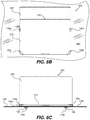
- FIGS. 6A, 6B, and 6C illustrate respectively a front perspective view, a top plan view, and a front plan view of the security system 102 securing a laptop 202 to a tabletop 240 of a display table.
- a tabletop 240 of the display table should include through-holes that are appropriately located (i.e., spaced apart) so as to accept the fasteners 118 a , 118 b that extend downwards from the brackets 104 a , 104 b .
- the through-holes can be drilled in appropriate locations, or can be prearranged in a predetermined patterns of rows and columns of through-holes.
- nuts 126 e.g., wingnuts
- fastener hardware can then be used to secure the left and right brackets 104 a and 104 b to a tabletop 240 of a display table from the underside of the tabletop 240 .
- the underside of the tabletop 240 is made inaccessible to customers and potential thieves in a retail store, e.g., by being encased in a locked enclosure. This way potential thieves cannot remove the security system 102 from the display table, and thus, could not steal the laptop 202 that is secured to the display table by the security system 102 .
- Each of the elements of the security system 102 are preferably made of a strong metal or alloy (aka metal/alloy) so that the security system 102 is sturdy and cannot be readily bent, cut through, or otherwise broken or tempered with.
- a strong metal or alloy aka metal/alloy
- such elements can be made of steel.
- Different elements of the security system 102 can be made of the same metal/alloy or different metals/alloys than other elements. All or subsets of such elements can be painted, powder coated, or otherwise covered to have any desired color and appearance.
- Certain elements of the security system 102 can be molded and/or machined.
- all of the elements of the security system 102 can be made from blanks that are cut (e.g., laser cut or mechanically cut) or stamped from a sheet of metal/alloy, and then bent into a desired final configuration.
- the through-holes in the various elements can be made before or after the aforementioned bending and/or cutting, as noted above.
- certain components of the quickly customizable security system 102 may be kept in inventory a variety of different sizes, while other components of the quickly customizable security system are designed such that they can be manufactured and assembled with a very short lead-time (e.g., in just a few days, and likely in just a few hours).
- certain components of the quickly customizable security system 102 such as the corner and side braces 130 and 140 that can be manufactured such that they can be used with laptops having a lower body portion within a certain range of thicknesses, wherein such components can be referred to as selectable standard components.
- a first sized corner brace 130 can include a corner element 132 for use with a lower body portion of a laptop having a thickness in the range of 0.39 to 0.41 inches; a second sized corner brace 130 can include a corner element 132 for use with a lower body portion of a laptop having a thickness in the range of 0.42 to 0.44 inches; and a third sized corner brace 130 can include a corner element 132 for use with a lower body portion of a laptop having a thickness in the range of 0.45 to 0.47 inches.
- Different sized side braces can also be manufactured for use with laptops having a lower body portion within certain ranges of thicknesses.
- the components that may be stocked in various different sizes include, e.g., the corner braces 130 and the side braces 140 , which can be stocked for use with laptops having lower body portions of different thicknesses.
- the various fasteners and fastener hardware can also be kept in stock.
- the components that are designed such that they can be manufactured and assembled with a very short lead-time e.g., in just a few days, and likely in just a few hours
- quickly manufacturable customized components or more succinctly, as customized components.
- the customized components include, but are not limited to, the left and right bottom support substrates 110 a , 110 b , which as noted above can be made from blanks 108 a , 108 b that are cut from one or more sheets of metal or alloy and appropriately bent, etc.
- the corner and side braces 130 , 140 are also made from blanks that are cut from sheet(s) of metal or alloy and appropriately bent, etc., the corner and side braces 130 , 140 can also be customized components.
- a company that makes and sells security systems can stock the certain components (e.g., the selectable standard components) in a single color (e.g., white) with a single finish (matte), or in multiple colors (e.g., white, black, and silver) and/or multiple finishes (e.g., matte, glossy, and semi-gloss).
- the company can also stock the selectable standard components in each of a plurality of sizes, in a single color and a single finish, or in multiple different colors and/or multiple different finishes.
- the company that makes and sells security systems can quickly design the custom components, e.g., using computer aided design software, or the like, and then use computer controlled cutting or stamping equipment to quickly cut custom blanks (e.g., the same as or similar to the blanks 108 a and 108 b shown in FIGS. 2A and 2B , and then add holes and/or bends to the blanks as appropriate to produce bottom support substrates (the same as or similar to the bottom support substrate 110 a , 110 b ).
- the entire system 102 (except, e.g., for the fasteners and fastener hardware) be customized for a specific laptop and manufactured with very little lead time, e.g., within a few days or even within a few hours.
- a company that makes and sells security systems may receive an order for a specific quantity of quickly customizable security systems that are customized to hold a specific model of a specific company's laptop.
- a big-box store may order two hundred security systems that are intended to be used to display and secure the latest model of a laptop in two hundred of the big-box store's locations.
- the company that makes and sells the security systems, or a subcontractor, or the like can complete the order by selecting certain components from their stock of universal components (e.g., fasteners and fastener hardware) and their stock of selectable standard components (e.g., corner and side braces 130 and 140 ), and the company can quickly design and make the custom components, and then ship the components along with assembly instructions to the big-box store.
- universal components e.g., fasteners and fastener hardware
- selectable standard components e.g., corner and side braces 130 and 140
- the company that makes and sells the security systems can appropriately attach such elements to one another, or use a subcontractor, or the like, to perform such tasks, prior to such components being shipped to the big-box store or other type of retail store.
- All of the components that are needed to assemble a single security system (e.g., 102 ) that is for using in securing a single laptop to a display table can be shipped in a single unit box or bag, and a plurality of such single unit boxes or bags can be shipped in a larger box or bag. Assembly instructions can be included in each single unit box or bag, or just in the larger box or bag that includes multiple such single unit boxes or bags. Referring briefly back to FIG. 1A , all the components shown therein can be placed in a single unit box or bag.
- corner and side braces 130 and 140 should already be secured to the corner and side brace supports 112 and 114 of the bottom support substrates 110 a , 110 b before such elements are placed in a single unit box or bag and shipped to a retail store.
- Fastener hardware such as wingnuts, is preferably also included with the single unit box or bag.
- a worker can open a single unit box or bag and remove the components thereof.
- the worker will maneuver the left and right brackets 104 a , 104 b relative to a lower body portion (e.g., 212 ) of a laptop (e.g., 202 ) such that the left corner and left side braces 130 a , 140 a of the left bracket 104 a encase a portion of a lower left front corner and a left side of the lower body portion of the laptop and the left rear flange 120 a is behind a left portion of the rear of the lower body portion of the laptop; and such that right corner and right side braces 130 b , 140 b of the right bracket 104 b encase a portion of a lower front right corner and a right side of the lower body portion of the laptop and the right rear flange 120 b is behind a right portion of the rear
- brackets 104 a , 104 b are secured to the lower body portion of the laptop (e.g., as shown in FIG. 6A ) with fasteners (e.g., bolts) 118 a , 118 b extending downward from the brackets 104 a , 104 b .
- the fasteners 118 a , 118 b e.g., bolts
- nuts 126 can then be used to secure the security system 102 to the tabletop 240 from the underside of the tabletop 240 .
- step 702 involves obtaining dimensions of the lower body portion of the laptop, including a depth and a thickness of the lower body portion of the laptop.
- FIG. 8A An example depth of a lower body portion 212 of a laptop 202 is shown in FIG. 8A , and an example thickness thereof is show in FIG. 8B .
- FIGS. 8A and 8B the lower body portion 212 of a laptop is shown in dashed lines.
- step 704 involves, based on the depth of the lower body portion of the laptop, designing and cutting or stamping first and second blanks for use in making a bottom support substrate portion, a rear flange portion, a front corner brace support portion, and a side brace support portion of each of left and right brackets of the system.
- Step 706 involves, based on the thickness of the lower body portion of the laptop, select from inventory left and right front corner braces and left and right side braces. Alternatively, step 706 involves cutting or stamping further blanks for use in making the left and right front corner braces and the left and right side braces.
- a gap of the corner braces e.g., shown in FIG. 3D
- a gap of the side braces is about 0.1 inches greater than a thickness of the front corners of a lower body portion of a laptop that the corner braces are being used to secure.
- a gap of the side braces e.g., shown in FIG.
- the gap of the corner braces and the gap of the side braces can be the same as one another, where the thickness of a lower portion of a laptop is consistent, or they may differ from another where the thickness of a lower portion of a laptop is not consistent (e.g., gradually increased in thickness from the front to the rear of the lower portion of the laptop).
- Step 708 involves adding through-holes to the first and second blanks.
- Step 708 can also include adding through-holes to the further blanks used to make the corner and side braces, if those are made from blanks.
- Step 710 involves bending the first and second blanks to demarcate the portions thereof that correspond to the bottom support substrate (e.g., 110 ) from the rear flange (e.g., 120 ). Step 710 can also include bending the further blanks to make the corner and side braces (e.g., 130 and 140 ), if those are made from blanks.
- Step 712 involves attaching the left front corner brace (e.g., 130 a ) and the left side brace (e.g., 140 a ) respectively to the front corner brace support portion (e.g., 112 a ) and the side brace support portion (e.g., 114 a ) of the first blank (e.g., 108 a ) and add fasteners (e.g., 118 a ) extending downward from the bottom support substrate portion of the first blank to thereby produce the left bracket (e.g., 104 a ).
- the left front corner brace e.g., 130 a
- the left side brace e.g., 140 a
- Step 712 also involves attaching the right front corner brace (e.g., 130 b ) and the right side brace (e.g., 140 b ) respectively to the front corner brace support portion (e.g., 112 b ) and the side brace support portion (e.g., 114 b ) of the second blank (e.g., 108 b ) and add fasteners (e.g., 118 b ) extending downward from the bottom support substrate portion of the second blank to thereby produce the second bracket (e.g., 104 b ).
- the right front corner brace e.g., 130 b
- the right side brace e.g., 140 b
- steps 708 and 710 can be reversed in order.
- steps 708 and 710 can be reversed in order.
- the steps described above can be separated into multiple sub-steps.
- step 704 can be separated into multiple sub-steps.
- steps 706 and 712 can each be separated into multiple sub-steps. Such sub-steps need not be performed in the specific order shown in FIG. 7 .
- the security systems of the embodiments of the present technology can be used to secure laptops to other display surfaces besides a horizontal display table.
- such systems can also be used to secure laptops to a vertical display wall, if desired, or more generally, to any one of various different types of display surfaces.
- a connection may be a direct connection or an indirect connection (e.g., via one or more other parts).
- the element when an element is referred to as being connected or coupled to another element, the element may be directly connected to the other element or indirectly connected to the other element via intervening elements.
- the element When an element is referred to as being directly connected to another element, then there are no intervening elements between the element and the other element.
Landscapes
- Engineering & Computer Science (AREA)
- General Engineering & Computer Science (AREA)
- Mechanical Engineering (AREA)
- Computer Hardware Design (AREA)
- Physics & Mathematics (AREA)
- Theoretical Computer Science (AREA)
- Mathematical Physics (AREA)
- Human Computer Interaction (AREA)
- General Physics & Mathematics (AREA)
- Casings For Electric Apparatus (AREA)
Abstract
Description
Claims (20)
Priority Applications (1)
| Application Number | Priority Date | Filing Date | Title |
|---|---|---|---|
| US16/531,555 US11045019B2 (en) | 2019-08-05 | 2019-08-05 | Quickly customizable systems that secure laptops to display tables and other display surfaces |
Applications Claiming Priority (1)
| Application Number | Priority Date | Filing Date | Title |
|---|---|---|---|
| US16/531,555 US11045019B2 (en) | 2019-08-05 | 2019-08-05 | Quickly customizable systems that secure laptops to display tables and other display surfaces |
Publications (2)
| Publication Number | Publication Date |
|---|---|
| US20210037992A1 US20210037992A1 (en) | 2021-02-11 |
| US11045019B2 true US11045019B2 (en) | 2021-06-29 |
Family
ID=74499015
Family Applications (1)
| Application Number | Title | Priority Date | Filing Date |
|---|---|---|---|
| US16/531,555 Active 2040-01-08 US11045019B2 (en) | 2019-08-05 | 2019-08-05 | Quickly customizable systems that secure laptops to display tables and other display surfaces |
Country Status (1)
| Country | Link |
|---|---|
| US (1) | US11045019B2 (en) |
Cited By (3)
| Publication number | Priority date | Publication date | Assignee | Title |
|---|---|---|---|---|
| US11739568B2 (en) | 2021-07-26 | 2023-08-29 | ONQ Solutions, Inc. | Apparatuses that secure laptops to display surfaces |
| US12276373B1 (en) | 2023-10-20 | 2025-04-15 | ONQ Solutions, Inc. | Apparatus to secure one or more electronic devices to a display table |
| US12385291B2 (en) | 2023-03-28 | 2025-08-12 | ONQ Solutions, Inc. | Adjustable security bracket for laptop computers |
Citations (7)
| Publication number | Priority date | Publication date | Assignee | Title |
|---|---|---|---|---|
| US6700488B1 (en) * | 2002-09-05 | 2004-03-02 | Se-Kure Controls, Inc. | Security system for a portable device |
| US7866623B2 (en) * | 2008-10-21 | 2011-01-11 | Sony Corporation | Computer retail display stand |
| US20110133050A1 (en) * | 2009-12-08 | 2011-06-09 | Firstgroup America, Inc. | Adjustable Mounting Assemblies with Locking Systems |
| US8074951B2 (en) * | 2007-05-31 | 2011-12-13 | Carnevali Jeffrey D | Quick release electronics platform |
| US9022337B2 (en) * | 2011-12-16 | 2015-05-05 | Halo Metrics Inc. | Apparatus and methods for securing products |
| US20180279809A1 (en) * | 2017-03-31 | 2018-10-04 | Sennco Solutions, Inc. | Rugged lockdown merchandise security apparatus |
| US10920922B2 (en) * | 2019-07-18 | 2021-02-16 | ONQ Solutions, Inc. | Quickly customizable apparatuses that secure portable electronic devices to display tables and other display surfaces |
-
2019
- 2019-08-05 US US16/531,555 patent/US11045019B2/en active Active
Patent Citations (8)
| Publication number | Priority date | Publication date | Assignee | Title |
|---|---|---|---|---|
| US6700488B1 (en) * | 2002-09-05 | 2004-03-02 | Se-Kure Controls, Inc. | Security system for a portable device |
| US8074951B2 (en) * | 2007-05-31 | 2011-12-13 | Carnevali Jeffrey D | Quick release electronics platform |
| US7866623B2 (en) * | 2008-10-21 | 2011-01-11 | Sony Corporation | Computer retail display stand |
| US20110024371A1 (en) * | 2008-10-21 | 2011-02-03 | Linda Lampman | Computer retail display stand |
| US20110133050A1 (en) * | 2009-12-08 | 2011-06-09 | Firstgroup America, Inc. | Adjustable Mounting Assemblies with Locking Systems |
| US9022337B2 (en) * | 2011-12-16 | 2015-05-05 | Halo Metrics Inc. | Apparatus and methods for securing products |
| US20180279809A1 (en) * | 2017-03-31 | 2018-10-04 | Sennco Solutions, Inc. | Rugged lockdown merchandise security apparatus |
| US10920922B2 (en) * | 2019-07-18 | 2021-02-16 | ONQ Solutions, Inc. | Quickly customizable apparatuses that secure portable electronic devices to display tables and other display surfaces |
Cited By (3)
| Publication number | Priority date | Publication date | Assignee | Title |
|---|---|---|---|---|
| US11739568B2 (en) | 2021-07-26 | 2023-08-29 | ONQ Solutions, Inc. | Apparatuses that secure laptops to display surfaces |
| US12385291B2 (en) | 2023-03-28 | 2025-08-12 | ONQ Solutions, Inc. | Adjustable security bracket for laptop computers |
| US12276373B1 (en) | 2023-10-20 | 2025-04-15 | ONQ Solutions, Inc. | Apparatus to secure one or more electronic devices to a display table |
Also Published As
| Publication number | Publication date |
|---|---|
| US20210037992A1 (en) | 2021-02-11 |
Similar Documents
| Publication | Publication Date | Title |
|---|---|---|
| US11408551B2 (en) | Methods for providing quickly customizable apparatuses that secure portable electronic devices to display tables and other display surfaces | |
| US11045019B2 (en) | Quickly customizable systems that secure laptops to display tables and other display surfaces | |
| US20210059437A1 (en) | Adjustable apparatuses that secure laptop computers to display tables | |
| JP7142026B2 (en) | Judgment of product placement conformity results | |
| US7274557B2 (en) | Apparatus for mounting a display system to a front side of a surface | |
| US10646055B2 (en) | Adjustable size apparatuses that secure portable electronic devices to display tables | |
| US7267315B2 (en) | Assembled type of display apparatus | |
| JP5850594B1 (en) | Custom-made furniture design / order / manufacturing ordering system, method, and program therefor | |
| CA2155717A1 (en) | Electronic sourcing system and method | |
| US20200393079A1 (en) | Display stand for tablets | |
| US10736438B1 (en) | Display shelf lock box | |
| US20100138032A1 (en) | Method and system for merchandising complementary merchandise in floor space remnants created by primary merchandise | |
| US8171664B2 (en) | Configurable computer display stand bearing signage with a user-selected one of multiple orientations to physically conform to point of sale physical constraints | |
| EP3226667B1 (en) | Multi-piece rack shelf | |
| US8319792B2 (en) | Virtual components for CAD models | |
| US6367752B1 (en) | Electronic price label mounting apparatus | |
| US20200073437A1 (en) | Tablet computer surface mount | |
| US10405658B2 (en) | Auxiliary bracket for electronic display | |
| US12025262B1 (en) | Information handling system display stand mount | |
| US20050178298A1 (en) | Mobile storage and computer cart | |
| US8564959B2 (en) | System and method for attaching portion of equipment to remainder of equipment | |
| JP2011104003A (en) | Article storage rack | |
| US20030227484A1 (en) | System and method for visualization of objects using energy minimization of customized potential functions | |
| US20150223616A1 (en) | Modular merchandising system | |
| EP3525185A1 (en) | Input/output port mounting unit integrated type display frame for pos equipment |
Legal Events
| Date | Code | Title | Description |
|---|---|---|---|
| FEPP | Fee payment procedure |
Free format text: ENTITY STATUS SET TO UNDISCOUNTED (ORIGINAL EVENT CODE: BIG.); ENTITY STATUS OF PATENT OWNER: SMALL ENTITY |
|
| FEPP | Fee payment procedure |
Free format text: ENTITY STATUS SET TO SMALL (ORIGINAL EVENT CODE: SMAL); ENTITY STATUS OF PATENT OWNER: SMALL ENTITY |
|
| AS | Assignment |
Owner name: ONQ SOLUTIONS, INC., CALIFORNIA Free format text: ASSIGNMENT OF ASSIGNORS INTEREST;ASSIGNORS:CHAPUIS, PAUL F.;PENNY, STEVEN D.;REEL/FRAME:050123/0160 Effective date: 20190812 |
|
| STPP | Information on status: patent application and granting procedure in general |
Free format text: DOCKETED NEW CASE - READY FOR EXAMINATION |
|
| STPP | Information on status: patent application and granting procedure in general |
Free format text: NON FINAL ACTION MAILED |
|
| STPP | Information on status: patent application and granting procedure in general |
Free format text: RESPONSE TO NON-FINAL OFFICE ACTION ENTERED AND FORWARDED TO EXAMINER |
|
| STPP | Information on status: patent application and granting procedure in general |
Free format text: NOTICE OF ALLOWANCE MAILED -- APPLICATION RECEIVED IN OFFICE OF PUBLICATIONS |
|
| STPP | Information on status: patent application and granting procedure in general |
Free format text: PUBLICATIONS -- ISSUE FEE PAYMENT VERIFIED |
|
| STCF | Information on status: patent grant |
Free format text: PATENTED CASE |
|
| MAFP | Maintenance fee payment |
Free format text: PAYMENT OF MAINTENANCE FEE, 4TH YR, SMALL ENTITY (ORIGINAL EVENT CODE: M2551); ENTITY STATUS OF PATENT OWNER: SMALL ENTITY Year of fee payment: 4 |