US11039700B2 - Single double level swivel platform plates nozzle and pressurized convolution form method to process convergent stress energy flow in cylindrical container unit - Google Patents
Single double level swivel platform plates nozzle and pressurized convolution form method to process convergent stress energy flow in cylindrical container unit Download PDFInfo
- Publication number
- US11039700B2 US11039700B2 US16/123,376 US201816123376A US11039700B2 US 11039700 B2 US11039700 B2 US 11039700B2 US 201816123376 A US201816123376 A US 201816123376A US 11039700 B2 US11039700 B2 US 11039700B2
- Authority
- US
- United States
- Prior art keywords
- container
- liquid
- platform
- cavity body
- nozzle
- Prior art date
- Legal status (The legal status is an assumption and is not a legal conclusion. Google has not performed a legal analysis and makes no representation as to the accuracy of the status listed.)
- Active, expires
Links
- 238000000034 method Methods 0.000 title claims description 9
- 239000007788 liquid Substances 0.000 claims abstract description 65
- 238000002156 mixing Methods 0.000 claims abstract description 28
- 230000006835 compression Effects 0.000 claims abstract description 19
- 238000007906 compression Methods 0.000 claims abstract description 19
- 239000000463 material Substances 0.000 claims description 17
- 238000004140 cleaning Methods 0.000 claims description 11
- 239000012530 fluid Substances 0.000 claims description 2
- 230000000087 stabilizing effect Effects 0.000 claims 2
- 235000013361 beverage Nutrition 0.000 description 12
- 229920001971 elastomer Polymers 0.000 description 5
- 230000008901 benefit Effects 0.000 description 4
- 238000003756 stirring Methods 0.000 description 4
- 239000002184 metal Substances 0.000 description 3
- 229910052751 metal Inorganic materials 0.000 description 3
- 239000000203 mixture Substances 0.000 description 3
- 239000004033 plastic Substances 0.000 description 3
- 229920003023 plastic Polymers 0.000 description 3
- 229920001296 polysiloxane Polymers 0.000 description 3
- 238000000926 separation method Methods 0.000 description 3
- 239000000654 additive Substances 0.000 description 2
- 235000013399 edible fruits Nutrition 0.000 description 2
- 235000013305 food Nutrition 0.000 description 2
- 239000007791 liquid phase Substances 0.000 description 2
- 230000007246 mechanism Effects 0.000 description 2
- 239000008267 milk Substances 0.000 description 2
- 235000013336 milk Nutrition 0.000 description 2
- 210000004080 milk Anatomy 0.000 description 2
- 239000012071 phase Substances 0.000 description 2
- 239000010902 straw Substances 0.000 description 2
- XLYOFNOQVPJJNP-UHFFFAOYSA-N water Substances O XLYOFNOQVPJJNP-UHFFFAOYSA-N 0.000 description 2
- 235000014101 wine Nutrition 0.000 description 2
- 239000004115 Sodium Silicate Substances 0.000 description 1
- 241001122767 Theaceae Species 0.000 description 1
- 235000013334 alcoholic beverage Nutrition 0.000 description 1
- 235000013405 beer Nutrition 0.000 description 1
- 239000003795 chemical substances by application Substances 0.000 description 1
- 239000003086 colorant Substances 0.000 description 1
- 238000013270 controlled release Methods 0.000 description 1
- 239000006071 cream Substances 0.000 description 1
- 230000006837 decompression Effects 0.000 description 1
- 230000000694 effects Effects 0.000 description 1
- 238000001125 extrusion Methods 0.000 description 1
- 239000004744 fabric Substances 0.000 description 1
- 235000012041 food component Nutrition 0.000 description 1
- 235000013355 food flavoring agent Nutrition 0.000 description 1
- 239000005417 food ingredient Substances 0.000 description 1
- 239000011521 glass Substances 0.000 description 1
- 235000013882 gravy Nutrition 0.000 description 1
- 239000006193 liquid solution Substances 0.000 description 1
- 239000007769 metal material Substances 0.000 description 1
- 150000002739 metals Chemical class 0.000 description 1
- 230000037361 pathway Effects 0.000 description 1
- 238000005191 phase separation Methods 0.000 description 1
- 229920000642 polymer Polymers 0.000 description 1
- 239000002861 polymer material Substances 0.000 description 1
- 235000015067 sauces Nutrition 0.000 description 1
- NTHWMYGWWRZVTN-UHFFFAOYSA-N sodium silicate Chemical compound [Na+].[Na+].[O-][Si]([O-])=O NTHWMYGWWRZVTN-UHFFFAOYSA-N 0.000 description 1
- 229910052911 sodium silicate Inorganic materials 0.000 description 1
- 239000010935 stainless steel Substances 0.000 description 1
- 229910001220 stainless steel Inorganic materials 0.000 description 1
- 238000011144 upstream manufacturing Methods 0.000 description 1
- 235000013311 vegetables Nutrition 0.000 description 1
- 239000002023 wood Substances 0.000 description 1
Images


Classifications
-
- A—HUMAN NECESSITIES
- A47—FURNITURE; DOMESTIC ARTICLES OR APPLIANCES; COFFEE MILLS; SPICE MILLS; SUCTION CLEANERS IN GENERAL
- A47G—HOUSEHOLD OR TABLE EQUIPMENT
- A47G19/00—Table service
- A47G19/22—Drinking vessels or saucers used for table service
- A47G19/2205—Drinking glasses or vessels
- A47G19/2255—Details related to the connection between the liquid containing part and the supporting part
-
- A—HUMAN NECESSITIES
- A47—FURNITURE; DOMESTIC ARTICLES OR APPLIANCES; COFFEE MILLS; SPICE MILLS; SUCTION CLEANERS IN GENERAL
- A47G—HOUSEHOLD OR TABLE EQUIPMENT
- A47G19/00—Table service
- A47G19/22—Drinking vessels or saucers used for table service
- A47G19/2205—Drinking glasses or vessels
-
- A—HUMAN NECESSITIES
- A47—FURNITURE; DOMESTIC ARTICLES OR APPLIANCES; COFFEE MILLS; SPICE MILLS; SUCTION CLEANERS IN GENERAL
- A47J—KITCHEN EQUIPMENT; COFFEE MILLS; SPICE MILLS; APPARATUS FOR MAKING BEVERAGES
- A47J43/00—Implements for preparing or holding food, not provided for in other groups of this subclass
- A47J43/04—Machines for domestic use not covered elsewhere, e.g. for grinding, mixing, stirring, kneading, emulsifying, whipping or beating foodstuffs, e.g. power-driven
- A47J43/07—Parts or details, e.g. mixing tools, whipping tools
- A47J43/08—Driving mechanisms
- A47J43/09—Driving mechanisms with fluid drive, e.g. by jets
-
- B—PERFORMING OPERATIONS; TRANSPORTING
- B01—PHYSICAL OR CHEMICAL PROCESSES OR APPARATUS IN GENERAL
- B01F—MIXING, e.g. DISSOLVING, EMULSIFYING OR DISPERSING
- B01F25/00—Flow mixers; Mixers for falling materials, e.g. solid particles
- B01F25/20—Jet mixers, i.e. mixers using high-speed fluid streams
- B01F25/21—Jet mixers, i.e. mixers using high-speed fluid streams with submerged injectors, e.g. nozzles, for injecting high-pressure jets into a large volume or into mixing chambers
-
- B—PERFORMING OPERATIONS; TRANSPORTING
- B01—PHYSICAL OR CHEMICAL PROCESSES OR APPARATUS IN GENERAL
- B01F—MIXING, e.g. DISSOLVING, EMULSIFYING OR DISPERSING
- B01F25/00—Flow mixers; Mixers for falling materials, e.g. solid particles
- B01F25/20—Jet mixers, i.e. mixers using high-speed fluid streams
- B01F25/25—Mixing by jets impinging against collision plates
-
- B—PERFORMING OPERATIONS; TRANSPORTING
- B01—PHYSICAL OR CHEMICAL PROCESSES OR APPARATUS IN GENERAL
- B01F—MIXING, e.g. DISSOLVING, EMULSIFYING OR DISPERSING
- B01F25/00—Flow mixers; Mixers for falling materials, e.g. solid particles
- B01F25/40—Static mixers
- B01F25/45—Mixers in which the materials to be mixed are pressed together through orifices or interstitial spaces, e.g. between beads
- B01F25/452—Mixers in which the materials to be mixed are pressed together through orifices or interstitial spaces, e.g. between beads characterised by elements provided with orifices or interstitial spaces
- B01F25/4521—Mixers in which the materials to be mixed are pressed together through orifices or interstitial spaces, e.g. between beads characterised by elements provided with orifices or interstitial spaces the components being pressed through orifices in elements, e.g. flat plates or cylinders, which obstruct the whole diameter of the tube
- B01F25/45212—Mixers in which the materials to be mixed are pressed together through orifices or interstitial spaces, e.g. between beads characterised by elements provided with orifices or interstitial spaces the components being pressed through orifices in elements, e.g. flat plates or cylinders, which obstruct the whole diameter of the tube the elements comprising means for adjusting the orifices
-
- B—PERFORMING OPERATIONS; TRANSPORTING
- B01—PHYSICAL OR CHEMICAL PROCESSES OR APPARATUS IN GENERAL
- B01F—MIXING, e.g. DISSOLVING, EMULSIFYING OR DISPERSING
- B01F25/00—Flow mixers; Mixers for falling materials, e.g. solid particles
- B01F25/50—Circulation mixers, e.g. wherein at least part of the mixture is discharged from and reintroduced into a receptacle
- B01F25/54—Circulation mixers, e.g. wherein at least part of the mixture is discharged from and reintroduced into a receptacle provided with a pump inside the receptacle to recirculate the material within the receptacle
-
- B—PERFORMING OPERATIONS; TRANSPORTING
- B01—PHYSICAL OR CHEMICAL PROCESSES OR APPARATUS IN GENERAL
- B01F—MIXING, e.g. DISSOLVING, EMULSIFYING OR DISPERSING
- B01F33/00—Other mixers; Mixing plants; Combinations of mixers
- B01F33/50—Movable or transportable mixing devices or plants
- B01F33/501—Movable mixing devices, i.e. readily shifted or displaced from one place to another, e.g. portable during use
- B01F33/5011—Movable mixing devices, i.e. readily shifted or displaced from one place to another, e.g. portable during use portable during use, e.g. hand-held
- B01F33/50111—Small portable bottles, flasks, vials, e.g. with means for mixing ingredients or for homogenizing their content, e.g. by hand shaking
-
- B—PERFORMING OPERATIONS; TRANSPORTING
- B01—PHYSICAL OR CHEMICAL PROCESSES OR APPARATUS IN GENERAL
- B01F—MIXING, e.g. DISSOLVING, EMULSIFYING OR DISPERSING
- B01F35/00—Accessories for mixers; Auxiliary operations or auxiliary devices; Parts or details of general application
- B01F35/30—Driving arrangements; Transmissions; Couplings; Brakes
- B01F35/32—Driving arrangements
- B01F35/32005—Type of drive
- B01F35/3202—Hand driven
-
- B01F5/069—
-
- B01F5/108—
-
- B—PERFORMING OPERATIONS; TRANSPORTING
- B65—CONVEYING; PACKING; STORING; HANDLING THIN OR FILAMENTARY MATERIAL
- B65D—CONTAINERS FOR STORAGE OR TRANSPORT OF ARTICLES OR MATERIALS, e.g. BAGS, BARRELS, BOTTLES, BOXES, CANS, CARTONS, CRATES, DRUMS, JARS, TANKS, HOPPERS, FORWARDING CONTAINERS; ACCESSORIES, CLOSURES, OR FITTINGS THEREFOR; PACKAGING ELEMENTS; PACKAGES
- B65D1/00—Rigid or semi-rigid containers having bodies formed in one piece, e.g. by casting metallic material, by moulding plastics, by blowing vitreous material, by throwing ceramic material, by moulding pulped fibrous material or by deep-drawing operations performed on sheet material
- B65D1/22—Boxes or like containers with side walls of substantial depth for enclosing contents
- B65D1/26—Thin-walled containers, e.g. formed by deep-drawing operations
- B65D1/265—Drinking cups
-
- B—PERFORMING OPERATIONS; TRANSPORTING
- B65—CONVEYING; PACKING; STORING; HANDLING THIN OR FILAMENTARY MATERIAL
- B65D—CONTAINERS FOR STORAGE OR TRANSPORT OF ARTICLES OR MATERIALS, e.g. BAGS, BARRELS, BOTTLES, BOXES, CANS, CARTONS, CRATES, DRUMS, JARS, TANKS, HOPPERS, FORWARDING CONTAINERS; ACCESSORIES, CLOSURES, OR FITTINGS THEREFOR; PACKAGING ELEMENTS; PACKAGES
- B65D23/00—Details of bottles or jars not otherwise provided for
- B65D23/04—Means for mixing or for promoting flow of contents
-
- B01F13/002—
-
- B—PERFORMING OPERATIONS; TRANSPORTING
- B01—PHYSICAL OR CHEMICAL PROCESSES OR APPARATUS IN GENERAL
- B01F—MIXING, e.g. DISSOLVING, EMULSIFYING OR DISPERSING
- B01F2101/00—Mixing characterised by the nature of the mixed materials or by the application field
- B01F2101/06—Mixing of food ingredients
- B01F2101/14—Mixing of ingredients for non-alcoholic beverages; Dissolving sugar in water
-
- B—PERFORMING OPERATIONS; TRANSPORTING
- B01—PHYSICAL OR CHEMICAL PROCESSES OR APPARATUS IN GENERAL
- B01F—MIXING, e.g. DISSOLVING, EMULSIFYING OR DISPERSING
- B01F25/00—Flow mixers; Mixers for falling materials, e.g. solid particles
- B01F25/40—Static mixers
- B01F25/438—Static mixers with movable slits formed between reciprocating surfaces
-
- B—PERFORMING OPERATIONS; TRANSPORTING
- B01—PHYSICAL OR CHEMICAL PROCESSES OR APPARATUS IN GENERAL
- B01F—MIXING, e.g. DISSOLVING, EMULSIFYING OR DISPERSING
- B01F33/00—Other mixers; Mixing plants; Combinations of mixers
- B01F33/50—Movable or transportable mixing devices or plants
- B01F33/501—Movable mixing devices, i.e. readily shifted or displaced from one place to another, e.g. portable during use
- B01F33/5011—Movable mixing devices, i.e. readily shifted or displaced from one place to another, e.g. portable during use portable during use, e.g. hand-held
-
- B01F5/066—
Definitions
- This application generally relates to beverage containers with a mixing mechanism.
- the present invention produces convergent forced circulation that is designed to prevent liquid separation in the container.
- An object is not to use any conventional loose single beverage related items such as spoons, straws, stir sticks to stir or mix the beverage.
- the new invention seeks to improve upon old conventional alternatives in choosing a better way to enjoy a beverage and other usage for the new invention.
- the invention teaches pressurized vacuum lock suction on liquid stress that creates flow circulation in a container.
- the invention's solution of mixing or force cleaning through its platform plates and elastic methods are in the bottom portion unit.
- Some embodiments use stretchable fabrics such as rubber, silicone, metals, polymer material that work together the manual platform's level plate.
- the platform's level plate surface benefits from the functional energy liquid flow from these materials.
- the container operate by way of a vacuum lock suction.
- the platform plate can be in the configuration of a single level with constantly open release holes or a double level with closeable release holes.
- the release holes fluidly connect the compressible cavity with the vessel.
- the platform sits over a compressible cavity's convoluted shape walls.
- the present invention provides a single or double level swivel platform plates, a nozzle and convolution walls in a compressible cavity body.
- This invention can be manually controlled by hand and used for multiple application purposes, such as keep liquid circulating for balance of taste, color, consistency of texture, force stress cleaning.
- an object of this invention is to provide forced circulation that has the benefit of cleaning small parts, mixing beverage liquids of all types and consistencies, cleaning of small fruits and cut vegetables in a kitchenware accessories context, cleaning small instruments and items in an industrial liquid cleaning context, cleaning small bolts, screws and other items in liquid degreasers items in auto mechanic shop environments, mixing food ingredients for use in kitchenware accessories in making gravy sauce, and preventing or removing liquid or phase separation.
- FIGS. 1A-1B are respectively a perspective view and a cross sectional view of the platform and nozzle.
- FIGS. 2A-2G are a mix of perspective and side views of the compressible cavity body and platform.
- FIGS. 3A-3D are respectively side, perspective, bottom and exploded views of an embodiment with a double-level platform, swivel axle and nozzle.
- FIGS. 4A-4B is a view of liquid reservoir with lines or markings for notifying such as measure desired liquid level in the container opening based on a calculated volume of headspace needed to avoid spills created by mixing.
- FIGS. 5A-5B is a close-up cross-sectional view of a single level platform container having accordion-like bellow convolutions in a compressed and uncompressed state.
- FIGS. 6A-6B is a close-up cross-sectional view of a double level platform container having accordion-like bellow convolutions in a compressed and uncompressed state.
- FIGS. 7A-7D are distant cross-sectional and non-cross-sectional views of single or double level platform (platform detail not shown) container having accordion-like bellow convolutions in a compressed and uncompressed state.
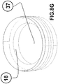
- FIGS. 8A-8M are various views of another embodiment.
- FIGS. 8N-8Q are various views of another embodiment with a floppy straight wall type of convolutions.
- the present invention relates to the single- or double-level plate swivel platforms, a nozzle and a compressible cavity that forms convolutions it its walls and creates convergent flow upon the application of force and a top cylindrical container.
- This new invention has two different unit mechanisms in its bottom compressible cavity.
- the first embodiment of the container has three key factors: the platform's surface level plates, the nozzle, and cylindrical convolution walls and cylindrical firm floppy straight wall units.
- This second container embodiment has six key factors which is the main part called platform's surface level plates followed by the pin, nozzle, support crate, spring, cylindrical convolution walls and cylindrical firm floppy straight wall units.
- FIGS. 1A-1B shows an embodiment of this invention.
- FIG. 1A illustrates a single level platform 10 .
- the single level platform 10 has release holes 7 designed to enable backflow through the release holes 7 by suction upon release of a compressive force on the compressible cavity body 1 and pressurized turbine flow 9 in its cavity upon a compressive force on the compressible cavity body 1 .
- the opened wide release holes 7 freely access a much quicker vacuum back flow expansion.
- the convolution area 6 (referenced in later figures) in the walls of the compressible cavity body 1 returns back faster to its original shape within the compressible cavity.
- the platform 10 is designed to block force against its maximized platform surface to enhance flow through nozzle 3 .
- FIG. 1B shows a nozzle 3 that accelerates convergent flow from the compressible cavity body 1 into the cylinder.
- FIGS. 2A-2G shows an embodiment of this invention.
- FIG. 2A shows compressible cavity body 1 with single level platform plate 5 and nozzle 3 .
- Top threaded rim base 2 is set above the compressible cavity body's 1 convolution area 6 and is where the cylinder or vessel can be attached to the compressible cavity body.
- Nozzle 3 is attachable or detachable to attachment point 4 to the single Platform 5 .
- FIG. 2B illustrates convolution area 6 while the compressible cavity body is being compressed.
- the Platform 5 has release holes 7 to reduce or prevent a slow vacuum in the compressible cavity body 1 allowing back flow to the compressible cavity body.
- Convergent flow 8 is forced through the nozzle 3 and a controlled release divergent flow 9 moves through the release holes 7 .
- FIG. 1 shows compressible cavity body 1 with single level platform plate 5 and nozzle 3 .
- Top threaded rim base 2 is set above the compressible cavity body's 1 convolution area 6 and is where the cylinder or vessel can be attached to the
- FIG. 2C shows the top threaded rim base 2 set above convolution area 6 and the bottom base area 14 .
- FIG. 2D illustrates convolution of the convolution area 6 caused by the compressible cavity body 1 in a compressed state (stress mode). This compression causes the liquid in the compressible cavity body 1 to be under intense hydraulic pressure, which is released through the pathway through the nozzle 3 in a forced convergent turbine flow 8 .
- FIG. 2E shows a cut-away sectional view 18 of the nozzle 3 in the context of a perspective view of the platform and the compressible cavity body 1 .
- FIG. 2F shows the compressible cavity body 1 after the compression state is released where the convolutions are being reduced.
- FIG. 2G depicts a compressed cavity body 15 indicating an act of compression by way of physical hand pressure that creates an accelerated convergent turbine flow through its nozzle 3 .
- FIGS. 3A-3D shows an embodiment of this invention.
- FIG. 3A indicates a double-level platform 11 and a swivel axle 13 .
- the two-level platform is attached by way of swivel axle 13 , which here is shown as a clamp inserted in the center of the platform, sandwiching the upper-level plate and the lower-level plate together and allowing the plates to rotate relative to each other.
- the design purpose of the rotation is to enable a desired opening control divergent turbine flow to be dialed in through the desired position of the double level platform 11 .
- FIG. 3B illustrates the effect of this rotation on the release holes 7 on the double level platform 11 . From the perspective view, an area 12 of the lower-level plate is visible through the release holes 7 of the upper-level platform plate.
- this area 12 demonstrates that the lower plate's release holes are partially blocked due to the rotation allowing less release hole flow 9 .
- the swivel axle holds the platform plates close together. If the holes are wide open on the double level platform 11 they will cause less hydraulic stress on the liquid forcing convergent flow 8 through the nozzle at a lower rate.
- the platform's manual position can be controlled by hand to adjust circulation of outward flow separate from the convergent flow 8 through the nozzle 3 , a divergent flow 9 through the platform's release holes 7 .
- the platform's surface is designed to block pressure leakage to facilitate a powerful stress flow through its nozzle. If desired, at least a minimum flow from its platform release holes 7 can be dialed in to reduce or prevent a slow vacuum back flow to the compressible cavity body 1 .
- FIG. 3C shows a double level platform 11 held sandwiched together by the swivel axle 13 . At least one of the platform plates can be rotated for a desired opening control divergent turbine flow 9 .
- FIG. 3D shows an exploded view 19 of the swivel axle and double level platform 11 and nozzle.
- FIGS. 4A-4B shows an embodiment of hollow cylinder container 20 that acts as a liquid reservoir.
- FIG. 4A depicts a level indicator 16 of tolerated liquid volume for preventing spill out of the top of the hollow cylinder container 20 .
- Hollow cylinder container 20 has a threaded bottom end 17 to connect to the top base area 2 on the compressible cavity body 1 .
- FIGS. 5A-5B shows cross-sectional views of another embodiment of this invention.
- FIG. 5A illustrates a compressible cavity body 1 , single level platform 10 and a liquid reservoir in an uncompressed state.
- the single level platform 10 with its release holes 7 is designed to vacuum back flow much easier and quicker pressurized turbine flow 9 in its cavity.
- the opened wide release holes 7 allow the compressible cavity body 1 freely access a much quicker vacuum back flow upon expansion on its convoluted walls upon release of the compression.
- the convolution area 6 returns back faster to its original shape within the compressible cavity body 1 as a result of the open release holes 7 .
- FIG. 5A depicts the convolution area as uncompressed accordion-like bellows 21 .
- FIG. 5B illustrates the same embodiment under compression.
- FIG. 5B depicts compressed accordion-like bellows 22 .
- FIGS. 6A-6B shows cross-sectional views of a similar embodiment to that shown in FIGS. 5A-5B except that the single level platform 10 is replaced with double level platform 11 .
- FIGS. 7A-7D are distant cross-sectional and non-cross-sectional views of single or double level platform (platform detail not shown) containers having accordion-like bellow convolutions in a compressed and uncompressed state.
- FIG. 7A shows a cross-section 25 of the container uncompressed.
- FIG. 7B illustrates a whole complete finish view 26 of the container uncompressed.
- FIG. 7C shows a cross-section 27 of the container under compression.
- FIG. 7D illustrates a whole complete finish view 28 of the container under compression.
- FIGS. 8A-8M shows another embodiment of this invention.
- FIG. 8A shows an exploded view 29 of a compressible cavity body 1 , single level platform 10 and nozzle 3 .
- FIG. 8B shows a retaining pin fastener 30 designed uniquely for the container's bottom unit components. The Pin 30 screws into the container bottom. And the other components work simultaneously in an upward and downward on the pin's vertical stationary bottom threaded end 31 . Stopper 32 is designed to prevents drawback force from spring-loading that locates in small depressions surface such as nozzle 3 .
- FIG. 8C shows a nozzle 3 .
- FIG. 8D illustrates a single level platform 10 , which operates similarly to other single level platforms discussed herein.
- FIG. 8A shows an exploded view 29 of a compressible cavity body 1 , single level platform 10 and nozzle 3 .
- FIG. 8B shows a retaining pin fastener 30 designed uniquely for the container's bottom unit components. The Pin 30 screws into the container bottom. And the other components work
- FIG. 8E shows a circular support crate 33 designed to support the platform connected to pressurized springs 36 .
- the center of support crate 33 is a section abutted by the spring 66 intended to hole the spring 66 steady through compression and decompression.
- support crate 33 has an offset extrusion rim 35 on the crate's edges for the platform 10 / 11 swivel bottom area piece that is supported beneath the crate space to maneuver or rotate in the tight space.
- FIG. 8F shows a spring 36 that enables a stronger, faster return after compression is removed. Spring 36 produces constant force to return the compressible cavity body from a compressed state to an uncompressed state.
- FIG. 8G shows a top perspective sectional view inside the compressible cavity body 1 , container bottom, and convolution walls 18 .
- Convolution walls 18 remain flat in an uncompressed state.
- Container bottom includes a threaded pin hole 37 for pin 30 to fasten all components onto the container bottom.
- FIGS. 8H and 8I illustrate the connected pin 30 /pin hole 37 .
- FIG. 8H 's view 38 shows a transparent portion view of the bottom parts of the container in a compressed state whereas FIG. 8I 's view 39 show the same bottom parts of the container in an uncompressed state.
- FIG. 8J shows a component-level exploded view 40 of the bottom parts of the container tilted at an angle 40 .
- FIG. 8K shows a component-level exploded view 41 of the entire container tilted at an angle.
- FIG. 8L shows a horizontal component-level exploded view 42 of the container.
- FIG. 8M shows a component-level exploded view 43 of view 42 from a different angle.
- FIGS. 8N-8Q show another embodiment with a floppy convolution wall.
- FIG. 8N shows a perspective view 44 of the compressible cavity body 1 with a floppy straight walls 44 in an uncompressed state.
- the material for the floppy straight walls can be made from firm flexible rubber or silicone.
- FIG. 8O shows a transparent detailed view of the floppy straight walls 45 in an uncompressed state.
- FIG. 8P Illustrates floppy straight wall convoluted under a state of compression 46 .
- FIG. 8Q Illustrates a transparent detailed view of the floppy straight wall convoluted under a state of compression 47 .
- the convolution is in the shape of a round convex curve form.
- An object of the present invention to reduce loose items that are meant for stirring or mixing such as spoons, straws, stir sticks and also electric mixer coffee containers. And the other alternative for this present invention related purposes to these items that are meant to clean food and parts like for example the small metal parts washer unit and fruit sterilizer cleaner washer.
- This present invention can by controlled unaided with hand pressure.
- the single and double level platforms with swivel axle and nozzle can be devices of elastic polymeric material formed from the group consisting of rubber materials, polymeric material formed from the group consisting of plastic materials, stainless steel material is formed from the group consisting of metal materials, and wood material is formed from the group consisting of porous and fibrous structural tissue materials.
- the ease of attachment of the nozzle allows for changing different colors nozzles and different materials of nozzles.
- the compressible cavity body can be polymeric material is formed from the group consisting of plastic materials.
- the convolution walls can be elastic polymeric material is formed from the group consisting of rubber materials or can be made from firm flexible rubber, silicone, plastic, or polymers.
- the liquid reservoir can be formed from glass materials is formed from the group consisting of sodium silicate materials.
Landscapes
- Engineering & Computer Science (AREA)
- Chemical & Material Sciences (AREA)
- Chemical Kinetics & Catalysis (AREA)
- Mechanical Engineering (AREA)
- Ceramic Engineering (AREA)
- Food Science & Technology (AREA)
- Dispersion Chemistry (AREA)
- Details Of Rigid Or Semi-Rigid Containers (AREA)
- Non-Alcoholic Beverages (AREA)
Abstract
Description
-
- Stress force Flow—this present invention produces a jet plume convergent and divergent pressure within its platform and nozzle. The (P, 0′) and (T, 0)=[pressure and temperature upstream flow]. The nozzle uniquely qualifies as non-calibrated orifice flow, because the unique designed nozzle is not supported by any engine power entity on the part but can perform with only physical hand pressure.
- Liquid—multiple liquid agents can be used for forced circulation mixing in the present invention. The platforms or plates and nozzle can circulate hydrogen oxide (H2O) milk, tea with additives, wine, mix alcohol beverage, and coffee with additives for its oral liquid beverage consumers. The present invention can be used for cleaning applications in its container. Its platforms or plates and nozzle can produce convergent stress force pressure for cleaning small foods or small metal parts. The present invention is designed to handle strong cleaning liquid solutions on items used in its container.
Claims (20)
Priority Applications (1)
| Application Number | Priority Date | Filing Date | Title |
|---|---|---|---|
| US16/123,376 US11039700B2 (en) | 2018-07-18 | 2018-09-06 | Single double level swivel platform plates nozzle and pressurized convolution form method to process convergent stress energy flow in cylindrical container unit |
Applications Claiming Priority (2)
| Application Number | Priority Date | Filing Date | Title |
|---|---|---|---|
| US201862699854P | 2018-07-18 | 2018-07-18 | |
| US16/123,376 US11039700B2 (en) | 2018-07-18 | 2018-09-06 | Single double level swivel platform plates nozzle and pressurized convolution form method to process convergent stress energy flow in cylindrical container unit |
Publications (2)
| Publication Number | Publication Date |
|---|---|
| US20200022514A1 US20200022514A1 (en) | 2020-01-23 |
| US11039700B2 true US11039700B2 (en) | 2021-06-22 |
Family
ID=69162688
Family Applications (1)
| Application Number | Title | Priority Date | Filing Date |
|---|---|---|---|
| US16/123,376 Active 2039-10-30 US11039700B2 (en) | 2018-07-18 | 2018-09-06 | Single double level swivel platform plates nozzle and pressurized convolution form method to process convergent stress energy flow in cylindrical container unit |
Country Status (1)
| Country | Link |
|---|---|
| US (1) | US11039700B2 (en) |
Families Citing this family (3)
| Publication number | Priority date | Publication date | Assignee | Title |
|---|---|---|---|---|
| CN111772446A (en) * | 2020-07-29 | 2020-10-16 | 上海超高环保科技股份有限公司 | Slow-release cup containing trace elements and manufacturing method thereof |
| CN111789468A (en) * | 2020-07-29 | 2020-10-20 | 上海超高环保科技股份有限公司 | Slow-release cup containing rare earth trace elements and manufacturing method thereof |
| US12016476B1 (en) * | 2023-05-22 | 2024-06-25 | John Sanfilippo | Glassware for making a multi-layer beverage, and a method of using the same |
Citations (9)
| Publication number | Priority date | Publication date | Assignee | Title |
|---|---|---|---|---|
| US5683732A (en) * | 1993-09-18 | 1997-11-04 | Bass Plc | Carbonated beverage container and method of manufacture therefore |
| US20090301032A1 (en) * | 2006-01-12 | 2009-12-10 | Packaging & Product Innovations Europe B.V. | Container, use of a container, additive chamber, and method for filling a container |
| US20120031277A1 (en) * | 2010-08-08 | 2012-02-09 | Chun-Shu Hsieh | Drink can |
| US20130075287A1 (en) * | 2010-06-03 | 2013-03-28 | Tal Sharon | Container having two or more compartments |
| US20150321807A1 (en) * | 2012-12-13 | 2015-11-12 | Tlc Design Limited | Storage Container |
| US20160038378A1 (en) * | 2014-08-06 | 2016-02-11 | Muneer AL-HAKIM | Chambered bottle |
| US9650197B1 (en) * | 2015-12-01 | 2017-05-16 | Marios Efstathiou | Collapsible portable container and method for mixing two substances |
| US20170203947A1 (en) * | 2016-01-15 | 2017-07-20 | Pepsico, Inc. | Post-mix beverage system |
| US9745115B2 (en) * | 2014-02-10 | 2017-08-29 | Joshua Hall | Multi-compartment, portable beverage container |
-
2018
- 2018-09-06 US US16/123,376 patent/US11039700B2/en active Active
Patent Citations (9)
| Publication number | Priority date | Publication date | Assignee | Title |
|---|---|---|---|---|
| US5683732A (en) * | 1993-09-18 | 1997-11-04 | Bass Plc | Carbonated beverage container and method of manufacture therefore |
| US20090301032A1 (en) * | 2006-01-12 | 2009-12-10 | Packaging & Product Innovations Europe B.V. | Container, use of a container, additive chamber, and method for filling a container |
| US20130075287A1 (en) * | 2010-06-03 | 2013-03-28 | Tal Sharon | Container having two or more compartments |
| US20120031277A1 (en) * | 2010-08-08 | 2012-02-09 | Chun-Shu Hsieh | Drink can |
| US20150321807A1 (en) * | 2012-12-13 | 2015-11-12 | Tlc Design Limited | Storage Container |
| US9745115B2 (en) * | 2014-02-10 | 2017-08-29 | Joshua Hall | Multi-compartment, portable beverage container |
| US20160038378A1 (en) * | 2014-08-06 | 2016-02-11 | Muneer AL-HAKIM | Chambered bottle |
| US9650197B1 (en) * | 2015-12-01 | 2017-05-16 | Marios Efstathiou | Collapsible portable container and method for mixing two substances |
| US20170203947A1 (en) * | 2016-01-15 | 2017-07-20 | Pepsico, Inc. | Post-mix beverage system |
Also Published As
| Publication number | Publication date |
|---|---|
| US20200022514A1 (en) | 2020-01-23 |
Similar Documents
| Publication | Publication Date | Title |
|---|---|---|
| US11039700B2 (en) | Single double level swivel platform plates nozzle and pressurized convolution form method to process convergent stress energy flow in cylindrical container unit | |
| RU2692283C2 (en) | Device for bottling beverages | |
| US6702138B1 (en) | Insulated beverage container and lid assembly | |
| US9723942B2 (en) | Brewing and filtering device for coffee and tea | |
| US5780087A (en) | Apparatus and method for frothing liquids | |
| US6481338B1 (en) | Spoon shaped coffee brewing apparatus | |
| US6095676A (en) | Dairy product whipping apparatus | |
| US20060021524A1 (en) | Plunger and lid apparatus for a beverage press and a beverage press having same | |
| US6561390B2 (en) | Coffee carafe with hidden handle support | |
| US20230200588A1 (en) | Multi-Functional Beverage Container | |
| US20170183610A1 (en) | Modular liquid infusing, flavoring, and dispensing device | |
| US20030002385A1 (en) | Convertible drink shaker and glass | |
| US20020153344A1 (en) | Convertible drink shaker and glass | |
| JP2010526622A (en) | Dispenser for fluids, especially liquid soap | |
| US20150208849A1 (en) | Infusers and Infusion Devices | |
| AU2011256114A1 (en) | A vessel for dispensing a fluid contained therein | |
| US6367661B1 (en) | Cup cake hopper | |
| US20040074923A1 (en) | Air pumping type fixed quantity dispensing container | |
| US20080008802A1 (en) | Squeezable colander | |
| AU706970B3 (en) | Latte and beverage layer-spoon | |
| EP4193886B1 (en) | Filtering beaker, kit and device for producing a liquid emulsion | |
| WO2010052509A1 (en) | Hygienic colanders and the like | |
| CN207023860U (en) | Drip-proof type coffee cup | |
| CN210079419U (en) | Foaming accessory for stirrer and stirrer tank | |
| JP2005328946A (en) | mixer |
Legal Events
| Date | Code | Title | Description |
|---|---|---|---|
| FEPP | Fee payment procedure |
Free format text: ENTITY STATUS SET TO UNDISCOUNTED (ORIGINAL EVENT CODE: BIG.); ENTITY STATUS OF PATENT OWNER: MICROENTITY |
|
| FEPP | Fee payment procedure |
Free format text: ENTITY STATUS SET TO MICRO (ORIGINAL EVENT CODE: MICR); ENTITY STATUS OF PATENT OWNER: MICROENTITY |
|
| STPP | Information on status: patent application and granting procedure in general |
Free format text: NON FINAL ACTION MAILED |
|
| STPP | Information on status: patent application and granting procedure in general |
Free format text: RESPONSE TO NON-FINAL OFFICE ACTION ENTERED AND FORWARDED TO EXAMINER |
|
| STPP | Information on status: patent application and granting procedure in general |
Free format text: NOTICE OF ALLOWANCE MAILED -- APPLICATION RECEIVED IN OFFICE OF PUBLICATIONS |
|
| FEPP | Fee payment procedure |
Free format text: ENTITY STATUS SET TO MICRO (ORIGINAL EVENT CODE: MICR); ENTITY STATUS OF PATENT OWNER: MICROENTITY |
|
| STPP | Information on status: patent application and granting procedure in general |
Free format text: PUBLICATIONS -- ISSUE FEE PAYMENT RECEIVED |
|
| STPP | Information on status: patent application and granting procedure in general |
Free format text: PUBLICATIONS -- ISSUE FEE PAYMENT VERIFIED |
|
| STCF | Information on status: patent grant |
Free format text: PATENTED CASE |
|
| MAFP | Maintenance fee payment |
Free format text: PAYMENT OF MAINTENANCE FEE, 4TH YEAR, MICRO ENTITY (ORIGINAL EVENT CODE: M3551); ENTITY STATUS OF PATENT OWNER: MICROENTITY Year of fee payment: 4 |