US11039415B2 - Downlink data transmission method, apparatus, and device - Google Patents
Downlink data transmission method, apparatus, and device Download PDFInfo
- Publication number
- US11039415B2 US11039415B2 US16/457,923 US201916457923A US11039415B2 US 11039415 B2 US11039415 B2 US 11039415B2 US 201916457923 A US201916457923 A US 201916457923A US 11039415 B2 US11039415 B2 US 11039415B2
- Authority
- US
- United States
- Prior art keywords
- base station
- paging message
- downlink data
- paging
- data
- Prior art date
- Legal status (The legal status is an assumption and is not a legal conclusion. Google has not performed a legal analysis and makes no representation as to the accuracy of the status listed.)
- Active
Links
Images


Classifications
-
- H—ELECTRICITY
- H04—ELECTRIC COMMUNICATION TECHNIQUE
- H04W—WIRELESS COMMUNICATION NETWORKS
- H04W4/00—Services specially adapted for wireless communication networks; Facilities therefor
- H04W4/20—Services signaling; Auxiliary data signalling, i.e. transmitting data via a non-traffic channel
-
- H—ELECTRICITY
- H04—ELECTRIC COMMUNICATION TECHNIQUE
- H04W—WIRELESS COMMUNICATION NETWORKS
- H04W68/00—User notification, e.g. alerting and paging, for incoming communication, change of service or the like
- H04W68/005—Transmission of information for alerting of incoming communication
-
- H—ELECTRICITY
- H04—ELECTRIC COMMUNICATION TECHNIQUE
- H04W—WIRELESS COMMUNICATION NETWORKS
- H04W68/00—User notification, e.g. alerting and paging, for incoming communication, change of service or the like
- H04W68/02—Arrangements for increasing efficiency of notification or paging channel
-
- H—ELECTRICITY
- H04—ELECTRIC COMMUNICATION TECHNIQUE
- H04W—WIRELESS COMMUNICATION NETWORKS
- H04W76/00—Connection management
- H04W76/20—Manipulation of established connections
- H04W76/27—Transitions between radio resource control [RRC] states
-
- H—ELECTRICITY
- H04—ELECTRIC COMMUNICATION TECHNIQUE
- H04W—WIRELESS COMMUNICATION NETWORKS
- H04W88/00—Devices specially adapted for wireless communication networks, e.g. terminals, base stations or access point devices
- H04W88/08—Access point devices
- H04W88/10—Access point devices adapted for operation in multiple networks, e.g. multi-mode access points
Definitions
- Mobile communication has experienced a leap-forward development from voice services to mobile bandwidth data services, which not only profoundly changed lifestyle of users, but also greatly promoted social and economic development.
- the mobile Internet and the Internet of Things (IoT) provide a broad application scenario for 5G.
- the present disclosure relates to wireless network technologies, and more particularly, to a method, an apparatus and an equipment for downlink data transmission.
- a method for downlink data transmission including: sending a paging message in a wireless notification area, the paging message carrying data need to be sent to a UE; and receiving a receipt confirmation message returned by the UE, the receipt confirmation message being indicative of the UE successfully receiving the data.
- the base station may directly carry the downlink data that needs to be sent to the UE in the paging message for sending, that is, the paging message sent by the base station to the UE includes data, and the UE may directly obtain the data.
- the data can be obtained without necessity to establish the connection state, thus data transmission efficiency can be effectively improved and data transmission delay can be reduced.
- the method prior to the sending a paging message in a wireless notification area, the method further includes: receiving the paging message sent by another base station; or, acquiring paging signaling, and generating the paging message by adding data into the signaling.
- the method further includes: sending the paging message to another base station, causing the other base station to send the paging message in a corresponding notification area.
- the paging message may be generated by the base station itself (i.e., the base station needs to send data to the UE), or may be received from other base stations.
- the UE may move all the time, for example, go far away from the initial paging area.
- the base station may also page the UE through other surrounding base stations, and send the paging message carrying the downlink data of the UE to other base stations, causing other base stations to broadcast the paging message so that the UE can acquire the data more quickly.
- the method further includes: sending the receipt confirmation message to the other base station.
- the base station may need to forward the receipt confirmation message to the base station that sends the paging message, so that the base station knows that the UE successfully received the data.
- the method prior to the sending a paging message in a wireless notification area, the method further comprises: determining the UE is currently in a wireless link inactive state.
- the solution provided by embodiments of the present disclosure is generally applied to a UE in a Radio Resource Control (RRC) inactive state, that is, the RRC_INACTIVE state.
- RRC Radio Resource Control
- the base station When determining that the UE is in the RRC inactive state, the base station does not need to wake up the UE, that is, does not need to perform an RRC establishment procedure with the UE. Instead, the data to be sent is directly carried in the paging message, so the downlink data is transmitted while paging the UE, thereby effectively improving the data transmission efficiency and reducing the data transmission delay.
- RRC Radio Resource Control
- a method for downlink data transmission including: receiving, by a UE, a paging message sent by a base station; detecting whether the paging message carries data sent by a base station to the UE; acquiring the data and generating a receipt confirmation message if the paging message carries data, the receipt confirmation message being indicative of the UE successfully receiving the data; and sending the receipt confirmation message to the base station.
- the method further includes: initiating, if the paging message does not carry data, an establishment procedure of a wireless resource link with the base station.
- the UE when receiving the paging message from the base station, the UE detects whether the paging message carries the downlink data sent to the UE, and the data may be identified with an identifier corresponding to the UE. If the data is included, the UE may acquire the data by decoding and generate the reception confirmation message to be returned to the base station. Otherwise, the UE may initiate the wireless link establishment procedure according to the paging instruction, so as to establish the wireless link for data transmission. In this way, the data transmission efficiency can be effectively improved, and the data transmission delay can be reduced.
- an apparatus for downlink data transmission including: a first sending module, configured to send a paging message in a wireless notification area, the paging message carrying data required to be sent to a user equipment (UE); and a first receiving module, configured to receive a receipt confirmation message returned by the UE, the receipt confirmation message being indicative of the UE successfully receiving the data.
- a first sending module configured to send a paging message in a wireless notification area, the paging message carrying data required to be sent to a user equipment (UE); and a first receiving module, configured to receive a receipt confirmation message returned by the UE, the receipt confirmation message being indicative of the UE successfully receiving the data.
- the apparatus further includes: a second receiving module, configured to receive the paging message sent by another base station; or, a first processing module, configured to acquire paging signaling, and generate the paging message by adding data into the signaling.
- the apparatus further includes: a second sending module, configured to send the receipt confirmation message to the other base station.
- the apparatus further includes: a third sending module, configured to send the paging message to another base station, causing the other base station to send the paging message in a corresponding notification area.
- the apparatus further includes: a second processing module, configured to determine the UE is currently in a wireless link inactive state.
- an apparatus for downlink data transmission including: a receiving module, configured to receive a paging message sent by a base station; a first processing module, configured to detect whether the paging message carries data sent by a base station to the apparatus for downlink data transmission; and configured to acquire the data and generate a receipt confirmation message if the paging message carries data, the receipt confirmation message being indicative of the UE successfully receiving the data; and a sending module, configured to send the receipt confirmation message to the base station.
- the apparatus further includes: a second processing module; the second processing module is configured to initiate, if the paging message does not carry data, an establishment procedure of a wireless resource link with the base station.
- a base station including: a memory configured to store processor-executable instructions, a processor configured to process an executable instruction, a receiver, and a transmitter; wherein the transmitter is configured to send a paging message in a wireless notification area, the paging message carrying data required to be sent to a user equipment (UE); and the receiver is configured to receive a receipt confirmation message returned by the UE, the receipt confirmation message being indicative of the UE successfully receiving the data.
- UE user equipment
- a UE including: a memory configured to store processor-executable instructions, a processor configured to process an executable instruction, a receiver, and a transmitter; wherein the receiver is configured to receive a paging message sent by a base station; the processor is configured to: detect whether the paging message carries data sent by a base station to the UE; and acquire the data and generate a receipt confirmation message if the paging message carries data, the receipt confirmation message being indicative of the UE successfully receiving the data; and the transmitter is configured to send the receipt confirmation message to the base station.
- the base station may directly carry the downlink data that needs to be sent to the UE in the paging message for sending, that is, the paging message sent by the base station to the UE includes data.
- the UE detects whether the paging message carries the downlink data sent to the UE. If the data is included, the UE may acquire the data directly. In other words, the data can be obtained without necessity to establish the connection state, thus data transmission efficiency can be effectively improved and data transmission delay can be reduced.
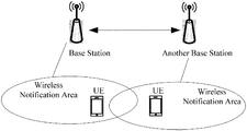
- FIG. 1 is a schematic diagram illustrating an application scenario of the downlink data transmission method according to some embodiments.
- FIG. 2 is a flowchart illustrating Embodiment 1 of the downlink data transmission method according to some embodiments.
- FIG. 3 is a flowchart illustrating Embodiment 2 of the downlink data transmission method according to some embodiments.
- FIG. 4 is a flowchart illustrating Embodiment 3 of the downlink data transmission method according to some embodiments.
- FIG. 5 is a block diagram illustrating Embodiment 1 of the downlink data transmission apparatus according to some embodiments.
- FIG. 6 is a block diagram illustrating Embodiment 2 of the downlink data transmission apparatus according to some embodiments.
- FIG. 7 is a block diagram illustrating Embodiment 3 of the downlink data transmission apparatus according to some embodiments.
- FIG. 8 is a block diagram illustrating Embodiment 4 of the downlink data transmission apparatus according to some embodiments.
- FIG. 9 is a block diagram illustrating Embodiment 5 of the downlink data transmission apparatus according to some embodiments.
- FIG. 10 is a block diagram illustrating Embodiment 6 of the downlink data transmission apparatus according to some embodiments.
- FIG. 11 is a block diagram illustrating Embodiment 7 of the downlink data transmission apparatus according to some embodiments.
- FIG. 12 is a block diagram illustrating an entity of the base station according to some embodiments.
- FIG. 13 is a block diagram illustrating an entity of the UE according to some embodiments.
- FIG. 14 is a block diagram illustrating a base station according to some embodiments.
- FIG. 15 is a block diagram illustrating a UE, according to some embodiments.
- LTE Long-Term Evolution
- UE user equipment
- FIG. 1 is a schematic diagram illustrating an application scenario of the downlink data transmission method according to some embodiments.
- the downlink data transmission method provided by the present disclosure may be applied between the base station and the UE.
- the scenario may include multiple base stations and multiple UEs.
- the UE may move within the coverage of the base station, and may move to the wireless notification area of other base stations (one of other base stations is taken as an example in FIG. 1 ), that is, move within the coverage of other base stations.
- the base station needs to perform downlink data transmission with the UE, the downlink data transmission method provided by the solution may be adopted, and the following technical solutions will be described with reference to the same UE.
- FIG. 2 is a flowchart illustrating Embodiment 1 of the downlink data transmission method according to some embodiments. As shown in FIG. 2 , the method may be applied at the base station side, the base station may include a macro base station, a micro base station, a radio remote station, a repeater station, or an indoor distribution system, and the like, and the disclosure is not limited thereto.
- the base station may include a macro base station, a micro base station, a radio remote station, a repeater station, or an indoor distribution system, and the like, and the disclosure is not limited thereto.
- the downlink data transmission method can include the following steps.
- step S 101 a paging message is transmitted in a wireless notification area, the paging message carrying data that needs to be transmitted to the UE.
- step S 102 a receipt confirmation message returned by the UE is received, the receipt confirmation message being indicative of that the UE successfully receives the data.
- the date when the data at the network side needs to be transmitted to a certain UE, the date may be directly sent to a UE in the connected state. If the UE is not connected or inactive, the downlink data to be sent may be carried in the paging message for transmission, which may be generally in a broadcasting way. The data may be identified with an identifier of the UE, so that the UE that receives the paging message is able to determine whether the data is sent to itself.
- the manner in which the base station obtains the paging message may include at least the following two types.
- the paging message is received from another base station.
- paging signaling is obtained, and the data is added in the signaling to generate the paging message.
- the base station may receive the paging message sent by another base station, which carries the paging instruction with respect to the UE and the downlink data to be sent to the UE.
- the paging message may be generated by the base station itself.
- the paging message may be generated by adding the data to be sent in a paging instruction, which is generated with respect to the UE based on requirement of data transmission.
- a receipt confirmation message may need to be returned to the base station, so that the base station is able to determine that the UE has correctly received the downlink data.
- the transmission method is preferably applied when the UE is in an inactive state.
- the base station may directly carry the data in the paging message sent to the UE.
- the UE receiving the paging message may directly obtain the data.
- the data can be obtained without necessity to establish the connection state, thus data transmission efficiency can be effectively improved and data transmission delay can be reduced.
- FIG. 3 is a flowchart illustrating Embodiment 2 of the downlink data transmission method according to some embodiments. As shown in FIG. 3 , on the basis of forgoing Embodiment 1, another implementation manner of the downlink data transmission method includes the following steps.
- step S 201 the paging message is sent to another base station, causing the other base station to send the paging message in a corresponding notification area.
- the base station may send the paging message to one or more other surrounding base stations while broadcasting the paging message by itself, so that the other base station(s) may broadcast the paging message.
- the base station may also receive a paging message from another base station(s), and broadcast the paging message sent by the other base station(s), so that the data may be received by the UE quickly.
- step S 202 the receipt confirmation message returned by the UE is received, the receipt confirmation message being indicative of that the UE successfully receives the data.
- the receipt confirmation message returned by the UE is received by another base station
- the receipt confirmation message returned by the UE as received is obtained through forwarding of the other base station, that is, the base station receives the receipt confirmation message sent by the UE through the other base station.
- the receipt confirmation message needs to be sent to the other base station.
- the UE may move all the time, for example, go far away from the initial paging area. Accordingly, in order to send data to the UE more quickly, the base station may also page the UE through other surrounding base stations, and send the paging message carrying the downlink data of the UE to other base stations, causing other base stations to broadcast the paging message so that the data can be acquired by the UE more quickly.
- the solution may be generally applied to a UE in the inactive state, that is, the RRC_INACTIVE state.
- the base station When determining that the UE is in the Radio Resource Control (RRC) inactive state, the base station does not need to wake up the UE, that is, does not need to perform an RRC establishment procedure with the UE. Instead, the data to be sent is directly carried in the paging message, so the downlink data is transmitted while paging the UE, thereby effectively improving the data transmission efficiency and reducing the data transmission delay.
- RRC Radio Resource Control
- FIG. 4 is a flowchart illustrating Embodiment 3 of the downlink data transmission method according to some embodiments.
- the solution may be applied at the user equipment side, and the user equipment may include any device requiring uplink and downlink data transmission, such as a mobile phone, a tablet computer, or the like.
- the downlink data transmission method may include following steps.
- step S 301 the UE receives a paging message sent by the base station.
- step S 302 it is detected whether the paging message carries data transmitted by the base station to the UE.
- step S 303 if data is carried in the paging message, the data is acquired and a receipt confirmation message is generated, the receipt confirmation message being indicative of that the UE successfully receives the data.
- step S 304 a receipt confirmation message is transmitted to the base station.
- the UE may be in the state without establishing a connection, or may be in the inactive state (also referred to as the light connection state), in which states the paging message of the base station can be received.
- the manner in which the base station sends the paging message may be broadcasting.
- the UE may need to detect whether the message carries any downlink data sent to the UE itself. If yes, the UE may directly obtain the data, and generate a receipt confirmation message to be returned to the base station, so that the base station acknowledges that the data is received by the UE. At the same time, an RRC link establishment may be performed according to a paging instruction in the paging message, so that data transmission can be performed subsequently.
- the UE may initiate an establishment procedure of wireless link according to the paging instruction, so as to establish the wireless link for data transmission.
- the UE when receiving the paging message from the base station, the UE detects whether the paging message carries the downlink data sent to the UE, and the data may be identified with an identifier corresponding to the UE. If the data is included, the UE may acquire the data by decoding and generate the reception confirmation message to be returned to the base station. Otherwise, the UE may initiate the wireless link establishment procedure according to the paging instruction, so as to establish the wireless link for data transmission. In this way, the data transmission efficiency can be effectively improved, and the data transmission delay can be reduced.
- the present disclosure provides a method for directly transmitting downlink data to a UE in the RRC_INACTIVE state.
- the gNB may send radio paging signaling in the radio notification area to page the UE, and add the data that needs to be transmitted into the paging signaling for transmission together.
- the gNB may send the paging signaling carrying the data information to all other gNBs in the wireless notification area, so that, upon receiving the paging signaling, the other gNBs may then broadcast the paging signaling within its own coverage.
- the UE may further detect whether the paging signaling includes a data portion. If the data portion is included, then the UE may continue to receive the data sent to itself contained in the radio paging signaling. If there is no data portion included, then the UE may attempt to establish an RRC connection with the gNB.
- the UE may further send a receipt confirmation signaling to the base station that sends the paging signaling, and the base station that receives the confirmation signaling may forwards the confirmation signaling to the gNB that initially sends the paging signaling, so that gNB may acknowledge that the data transmission is complete.
- the UE in the RRC_INACTIVE state is able to receive data without changing to the RRC_CONNECTED state, thereby increasing data transmission efficiency and reducing data transmission delay.
- FIG. 5 is a block diagram illustrating Embodiment 1 of the downlink data transmission apparatus according to some embodiments.
- the downlink data transmission apparatus 10 provided in this embodiment includes a first sending module 11 and a first receiving module 12 .
- modules may have modular configurations, or are composed of discrete components, but nonetheless may be referred to as “modules.”
- the first sending module 11 is configured to send a paging message in a wireless notification area, the paging message carrying data required to be sent to a UE.
- the first receiving module 12 is configured to receive a receipt confirmation message returned by the UE, the receipt confirmation message being indicative of the UE successfully receiving the data.
- the downlink data transmission apparatus provided by the embodiment of the present disclosure is configured to perform the technical solution of the base station side according to any of the foregoing method embodiments.
- the implementation principles and the technical solutions of the apparatus and of the method are similar to each other. That is, the downlink data that needs to be sent to the UE may be directly carried in the paging message for transmission, such that the UE is able to directly obtain the data. In other words, the data can be obtained without necessity to establish the connection state, thus data transmission efficiency can be effectively improved and data transmission delay can be reduced.
- FIG. 6 illustrates a block diagram of Embodiment 2 of the downlink data transmission apparatus according to some embodiments.
- the downlink data transmission apparatus 10 further includes a second receiving module 13 or a first processing module 14 .
- the second receiving module 13 is configured to receive the paging message sent by another base station.
- the first processing module 14 is configured to acquire paging signaling, and generate the paging message by adding data into the signaling.
- FIG. 7 illustrates a block diagram of Embodiment 3 of the downlink data transmission apparatus according to some embodiments.
- the downlink data transmission apparatus 10 further includes a second sending module 15 .
- the second sending module 15 is configured to send the receipt confirmation message to the other base station.
- FIG. 8 illustrates a block diagram of Embodiment 4 of the downlink data transmission apparatus according to some embodiments.
- the downlink data transmission apparatus 10 further includes a third sending module 16 .
- the third sending module 16 is configured to send the paging message to another base station, causing the other base station to send the paging message in a corresponding notification area.
- the downlink data transmission apparatus provided by any embodiment of the present disclosure is configured to perform the technical solution of the base station side according to any of the foregoing method embodiments.
- the implementation principles and the technical solutions of the apparatus and of the method are similar to each other. That is, the paging message carrying the downlink data of the UE may be sent to other base station(s), so that other base station(s) may broadcast the paging message. In other words, the paging message sent by other base station(s) is obtained and received for broadcasting, thereby enable the data to be received by the UE more quickly.
- FIG. 9 illustrates a block diagram of Embodiment 5 of the downlink data transmission apparatus according to some embodiments.
- the downlink data transmission apparatus 10 further includes a second processing module 17 .
- the second processing module 17 is configured to determine that the UE is currently in a wireless link inactive state.
- the downlink data transmission apparatus provided by the embodiment of the present disclosure is configured to perform the technical solution of the base station side according to any of the foregoing method embodiments.
- the implementation principles and the technical solutions of the apparatus and of the method are similar to each other. That is, the solution may be generally applied to a UE in the inactive state, that is, the RRC_INACTIVE state.
- the base station When determining that the UE is in the RRC inactive state, the base station does not need to wake up the UE, that is, does not need to perform an RRC establishment procedure with the UE. Instead, the data to be sent is directly carried in the paging message, so the downlink data is transmitted while paging the UE, thereby effectively improving the data transmission efficiency and reducing the data transmission delay.
- FIG. 10 is a block diagram illustrating Embodiment 6 of the downlink data transmission apparatus according to some embodiments.
- the downlink data transmission apparatus 20 includes a receiving module 21 , a first processing module 22 and a sending module 23 .
- the receiving module 21 is configured to receive a paging message sent by a base station.
- the first processing module 22 is configured to detect whether the paging message carries data sent by a base station to the apparatus for downlink data transmission; and configured to acquire the data and generate a receipt confirmation message if the paging message carries data, the receipt confirmation message being indicative of the UE successfully receiving the data.
- the sending module 23 is configured to send the receipt confirmation message to the base station.
- FIG. 11 is a block diagram illustrating Embodiment 7 of the downlink data transmission apparatus according to some embodiments.
- the downlink data transmission apparatus 20 further includes: a second processing module 24 .
- the second processing module 24 is configured to initiate, if the paging message does not carry data, an establishment procedure of a wireless resource link with the base station.
- the downlink data transmission apparatus provided by the embodiment shown in FIGS. 10 and 11 of the present disclosure is configured to perform the technical solution of the UE side according to any of the foregoing method embodiments.
- the implementation principles and the technical solutions of the apparatus and of the method are similar to each other. That is, when receiving the paging message from the base station, the UE detects whether the paging message carries the downlink data sent to the UE. If the data is included, the UE may acquire the data by decoding and generate the reception confirmation message to be returned to the base station. Otherwise, the UE may initiate the wireless link establishment procedure according to the paging instruction, so as to establish the wireless link for data transmission. In this way, the data transmission efficiency can be effectively improved, and the data transmission delay can be reduced.
- FIG. 12 is a block diagram illustrating an entity of the base station according to some embodiments.
- the base station may be specifically implemented as including: a memory configured to store processor-executable instructions, a processor configured to process an executable instruction, a receiver, and a transmitter.
- the transmitter is configured to send a paging message in a wireless notification area, the paging message carrying data need to be sent to UE.
- the receiver is configured to receive a receipt confirmation message returned by the UE, the receipt confirmation message being indicative of that the UE successfully receiving the data.
- FIG. 13 is a block diagram illustrating an entity of the UE according to some embodiments.
- the UE may be specifically implemented as including: a memory configured to store processor-executable instructions, a processor configured to process an executable instruction, a receiver, and a transmitter.
- the receiver is configured to receive a paging message sent by the base station.
- the processor is configured to: detect whether the paging message carries data sent by a base station to the UE; and acquire the data and generate a receipt confirmation message if the paging message carries data, the receipt confirmation message being indicative of the UE successfully receiving the data;
- the transmitter is configured to transmit the receipt confirmation message to the base station.
- the processor may be a central processing unit (CPU), or may be other general-purpose processors and digital signal processors (DSP), application specific integrated circuit (ASIC), and the like.
- the general-purpose processor may be a microprocessor or the processor may be any conventional processor or the like.
- the foregoing memory may be a read-only memory (ROM), a random-access memory (RAM), flash memory, hard disk or solid-state disk.
- ROM read-only memory
- RAM random-access memory
- flash memory hard disk or solid-state disk.
- FIG. 14 is a block diagram illustrating a base station 1100 according to some embodiments.
- the base station may be a station of any types such as a macro base station, a micro base station, a radio remote station, a repeater station, an indoor distribution system, and the like.
- the base station 1100 may include one or more of the following components: a processing component 1102 , a memory 1104 , a power component 1106 , a multimedia component 1108 , an audio component 1110 , an input/output (I/O) interface 1112 , a sensor component 1114 , and a communication component 1116 .
- the processing component 1102 typically controls overall operations of the base station 1100 , such as the operations associated with display, telephone calls, data communications, camera operations, and recording operations.
- the processing component 1102 may include one or more processors 1120 to execute instructions to perform all or part of the steps in the above described methods.
- the processing component 1102 may include one or more modules which facilitate the interaction between the processing component 1102 and other components.
- the processing component 1102 may include a multimedia module to facilitate the interaction between the multimedia component 1108 and the processing component 1102 .
- the memory 1104 is configured to store various types of data to support the operation of the base station 1100 . Examples of such data include instructions for any applications or methods operated on the base station 1100 , various types of data, messages, pictures, video, etc.
- the memory 1104 may be implemented using any type of volatile or non-volatile memory devices, or a combination thereof, such as a static random access memory (SRAM), an electrically erasable programmable read-only memory (EEPROM), an erasable programmable read-only memory (EPROM), a programmable read-only memory (PROM), a read-only memory (ROM), a magnetic memory, a flash memory, a magnetic or optical disk.
- SRAM static random access memory
- EEPROM electrically erasable programmable read-only memory
- EPROM erasable programmable read-only memory
- PROM programmable read-only memory
- ROM read-only memory
- magnetic memory a magnetic memory
- flash memory a flash memory
- magnetic or optical disk
- the power component 1106 provides power to various components of the base station 1100 .
- the power component 1106 may include a power management system, one or more power sources, and any other components associated with the generation, management, and distribution of power in the base station 1100 .
- the multimedia component 1108 includes a screen providing an output interface between the base station 1100 and the user.
- the screen may include a liquid crystal display (LCD), a light-emitting diode (LED) display such as an organic light-emitting diode (OLED) display, etc., and a touch panel (TP).
- LCD liquid crystal display
- LED light-emitting diode
- TP touch panel
- the screen may be implemented as a touch screen to receive input signals from the user.
- the touch panel includes one or more touch sensors to sense touches, slips, and gestures on the touch panel.
- the touch sensors may not only sense a boundary of a touch or slip action, but also sense a period of time and a pressure associated with the touch or slip action.
- the audio component 1110 is configured to output and/or input audio signals.
- the audio component 1110 includes a microphone (“MIC”) configured to receive an external audio signal when the base station 1100 is in an operation mode, such as a call mode, a recording mode, and a voice recognition mode.
- the received audio signal may be further stored in the memory 1104 or transmitted via the communication component 1116 .
- the audio component 1110 further includes a speaker to output audio signals.
- the I/O interface 1112 provides an interface between the processing component 1102 and peripheral interface modules, such as a keyboard, a click wheel, buttons, and the like.
- the sensor component 1114 includes one or more sensors to provide status assessments of various aspects of the base station 1100 .
- the sensor component 1114 may detect an open/closed status of the base station 1100 , relative positioning of components, e.g., the display and the keypad, of the base station 1100 , a change in position of the base station 1100 or a component of the base station 1100 , a presence or absence of user contact with the base station 1100 , an orientation or an acceleration/deceleration of the base station 1100 , and a change in temperature of the base station 1100 .
- the sensor component 1114 may include a proximity sensor configured to detect the presence of nearby objects without any physical contact.
- the sensor component 1114 may also include a light sensor, such as a CMOS or CCD image sensor, for use in imaging applications.
- the sensor component 1114 may also include an acceleration sensor, a gyroscope sensor, a magnetic sensor, a pressure sensor, or a temperature sensor.
- the sensor component 1114 may also include a fingerprint recognition sensor.
- the communication component 1116 is configured to facilitate communication, wired or wirelessly, between the base station 1100 and other devices.
- the base station 1100 can access a wireless network based on a communication standard, such as Wi-Fi, 2G, or 3G, or a combination thereof.
- the communication component 1116 receives a broadcast signal or broadcast associated information from an external broadcast management system via a broadcast channel.
- the communication component 1116 further includes a near field communication (NFC) module to facilitate short-range communications.
- NFC near field communication
- the NFC module may be implemented based on a radio frequency identification (RFID) technology, an infrared data association (IrDA) technology, an ultra-wideband (UWB) technology, a Bluetooth (BT) technology, and other technologies.
- RFID radio frequency identification
- IrDA infrared data association
- UWB ultra-wideband
- BT Bluetooth
- the base station 1100 may be implemented with one or more application specific integrated circuits (ASICs), digital signal processors (DSPs), digital signal processing devices (DSPDs), programmable logic devices (PLDs), field programmable gate arrays (FPGAs), controllers, micro-controllers, microprocessors, or other electronic components, for performing the forgoing downlink data transmission method, including: sending a paging message in a wireless notification area, the paging message carrying data need to be sent to a user equipment (UE); and receiving a receipt confirmation message returned by the UE, the receipt confirmation message being indicative of the UE successfully receiving the data.
- ASICs application specific integrated circuits
- DSPs digital signal processors
- DSPDs digital signal processing devices
- PLDs programmable logic devices
- FPGAs field programmable gate arrays
- controllers micro-controllers, microprocessors, or other electronic components
- Implementations of the subject matter and the operations described in this disclosure can be implemented in digital electronic circuitry, or in computer software, firmware, or hardware, including the structures disclosed herein and their structural equivalents, or in combinations of one or more of them.
- Implementations of the subject matter described in this disclosure can be implemented as one or more computer programs, i.e., one or more modules of computer program instructions, encoded on one or more computer storage medium for execution by, or to control the operation of, data processing apparatus.
- the program instructions can be encoded on an artificially-generated propagated signal, e.g., a machine-generated electrical, optical, or electromagnetic signal, that is generated to encode information for transmission to suitable receiver apparatus for execution by a data processing apparatus.
- an artificially-generated propagated signal e.g., a machine-generated electrical, optical, or electromagnetic signal
- a computer storage medium can be, or be included in, a computer-readable storage device, a computer-readable storage substrate, a random or serial access memory array or device, or a combination of one or more of them.
- a computer program (also known as a program, software, software application, script, or code) can be written in any form of programming language, including compiled or interpreted languages, declarative or procedural languages, and it can be deployed in any form, including as a stand-alone program or as a module, component, subroutine, object, or other unit suitable for use in a computing environment.
- a computer program may, but need not, correspond to a file in a file system.
- a program can be stored in a portion of a file that holds other programs or data (e.g., one or more scripts stored in a markup language document), in a single file dedicated to the program in question, or in multiple coordinated files (e.g., files that store one or more modules, sub-programs, or portions of code).
- a computer program can be deployed to be executed on one computer or on multiple computers that are located at one site or distributed across multiple sites and interconnected by a communication network.
- a computer storage medium is not a propagated signal
- a computer storage medium can be a source or destination of computer program instructions encoded in an artificially-generated propagated signal.
- the computer storage medium can also be, or be included in, one or more separate components or media (e.g., multiple CDs, disks, or other storage devices). Accordingly, the computer storage medium may be tangible.
- the operations described in this disclosure can be implemented as operations performed by a data processing apparatus on data stored on one or more computer-readable storage devices or received from other sources.
- Implementations of the subject matter described in this specification can be implemented in a computing system that includes a back-end component, e.g., as a data server, or that includes a middleware component, e.g., an application server, or that includes a front-end component, e.g., a client computer having a graphical user interface or a Web browser through which a user can interact with an implementation of the subject matter described in this specification, or any combination of one or more such back-end, middleware, or front-end components.
- a back-end component e.g., as a data server
- a middleware component e.g., an application server
- a front-end component e.g., a client computer having a graphical user interface or a Web browser through which a user can interact with an implementation of the subject matter described in this specification, or any combination of one or more such back-end, middleware, or front-end components.
- the components of the UE can be interconnected by any form or medium of digital data communication, e.g., a communication network.
- Examples of communication networks include a local area network (“LAN”) and a wide area network (“WAN”), an inter-network (e.g., the Internet), and peer-to-peer networks (e.g., ad hoc peer-to-peer networks).
- non-transitory computer readable storage medium comprising instructions, such as a memory 1104 including instructions executable by the processor 1120 of the base station 1100 to perform the above method.
- the non-transitory computer readable storage medium may be a ROM, a random-access memory (RAM), a CD-ROM, a magnetic tape, a floppy disk, and an optical data storage device.
- FIG. 15 is a block diagram illustrating a UE 1200 , according to some embodiments.
- the terminal device may be a smart phone, a computer, a transceiver device, a tablet device, or the like, which may require data transmission through a 3GPP network.
- the UE 1200 may include one or more of the following components: a processing component 1202 , a memory 1204 , a power component 1206 , a multimedia component 1208 , an audio component 1210 , an input/output (I/O) interface 1212 , a sensor component 1214 , and a communication component 1216 .
- the processing component 1202 typically controls overall operations of the UE 1200 , such as the operations associated with display, telephone calls, data communications, camera operations, and recording operations.
- the processing component 1202 may include one or more processors 1220 to execute instructions to perform all or part of the steps in the above described methods.
- the processing component 1202 may include one or more modules which facilitate the interaction between the processing component 1202 and other components.
- the processing component 1202 may include a multimedia module to facilitate the interaction between the multimedia component 1208 and the processing component 1202 .
- the memory device 1204 is configured to store various types of data to support the operation of the UE 1200 . Examples of such data include instructions for any applications or methods operated on the UE 1200 , various types of data, messages, pictures, video, etc.
- the memory 1204 may be implemented using any type of volatile or non-volatile memory devices, or a combination thereof, such as a static random access memory (SRAM), an electrically erasable programmable read-only memory (EEPROM), an erasable programmable read-only memory (EPROM), a programmable read-only memory (PROM), a read-only memory (ROM), a magnetic memory, a flash memory, a magnetic or optical disk.
- SRAM static random access memory
- EEPROM electrically erasable programmable read-only memory
- EPROM erasable programmable read-only memory
- PROM programmable read-only memory
- ROM read-only memory
- magnetic memory a magnetic memory
- flash memory a flash memory
- magnetic or optical disk
- the power component 1206 provides power to various components of the UE 1200 .
- the power component 1206 may include a power management system, one or more power sources, and any other components associated with the generation, management, and distribution of power in the UE 1200 .
- the multimedia component 1208 includes a screen providing an output interface between the UE 1200 and the user.
- the screen may include an LCD display, LED display, or OLED display, and a touch panel (TP). If the screen includes a touch panel, the screen may be implemented as a touch screen to receive input signals from the user.
- the touch panel includes one or more touch sensors to sense touches, slips, and gestures on the touch panel. The touch sensors may not only sense a boundary of a touch or slip action, but also sense a period of time and a pressure associated with the touch or slip action.
- the audio component 1210 is configured to output and/or input audio signals.
- the audio component 1210 includes a microphone (“MIC”) configured to receive an external audio signal when the UE 1200 is in an operation mode, such as a call mode, a recording mode, and a voice recognition mode.
- the received audio signal may be further stored in the memory 1204 or transmitted via the communication component 1216 .
- the audio component 1210 further includes a speaker to output audio signals.
- the I/O interface 1212 provides an interface between the processing component 1202 and peripheral interface modules, such as a keyboard, a click wheel, buttons, and the like.
- the sensor component 1214 includes one or more sensors to provide status assessments of various aspects of the UE 1200 .
- the sensor component 1214 may detect an open/closed status of the UE 1200 , relative positioning of components, e.g., the display and the keypad, of the UE 1200 , a change in position of the UE 1200 or a component of the UE 1200 , a presence or absence of user contact with the UE 1200 , an orientation or an acceleration/deceleration of the UE 1200 , and a change in temperature of the UE 1200 .
- the sensor component 1214 may include a proximity sensor configured to detect the presence of nearby objects without any physical contact.
- the sensor component 1214 may also include a light sensor, such as a CMOS or CCD image sensor, for use in imaging applications.
- the sensor component 1214 may also include an acceleration sensor, a gyroscope sensor, a magnetic sensor, a pressure sensor, or a temperature sensor.
- the sensor component 1214 may also include a fingerprint recognition sensor.
- the communication component 1216 is configured to facilitate communication, wired or wirelessly, between the UE 1200 and other devices.
- the UE 1200 can access a wireless network based on a communication standard, such as Wi-Fi, 2G, or 3G, or a combination thereof.
- the communication component 1216 receives a broadcast signal or broadcast associated information from an external broadcast management system via a broadcast channel.
- the communication component 1216 further includes a near field communication (NFC) module to facilitate short-range communications.
- the NFC module may be implemented based on a radio frequency identification (RFID) technology, an infrared data association (IrDA) technology, an ultra-wideband (UWB) technology, a Bluetooth (BT) technology, and other technologies.
- RFID radio frequency identification
- IrDA infrared data association
- UWB ultra-wideband
- BT Bluetooth
- the UE 1200 may be implemented with one or more application specific integrated circuits (ASICs), digital signal processors (DSPs), digital signal processing devices (DSPDs), programmable logic devices (PLDs), field programmable gate arrays (FPGAs), controllers, micro-controllers, microprocessors, or other electronic components, for performing the forgoing downlink data transmission method, including: receiving, by the UE, a paging message sent by a base station; detecting whether the paging message carries data sent by a base station to the UE; acquiring the data and generating a receipt confirmation message if the paging message carries data, the receipt confirmation message being indicative of the UE successfully receiving the data; and sending the receipt confirmation message to the base station.
- ASICs application specific integrated circuits
- DSPs digital signal processors
- DSPDs digital signal processing devices
- PLDs programmable logic devices
- FPGAs field programmable gate arrays
- controllers micro-controllers, microprocessors, or other electronic
- non-transitory computer readable storage medium comprising instructions, such as a memory 1204 including instructions executable by processor 1220 of user device 1200 to perform the above method.
- the non-transitory computer readable storage medium may be a ROM, a random-access memory (RAM), a CD-ROM, a magnetic tape, a floppy disk, and an optical data storage device.
- processors suitable for the execution of the instructions include, by way of example, both general and special purpose microprocessors, and any one or more processors of any kind of digital computer.
- a processor will receive instructions and data from a read-only memory, or a random-access memory, or both.
- Elements of a computer can include a processor configured to perform actions in accordance with instructions and one or more memory devices for storing instructions and data.
Landscapes
- Engineering & Computer Science (AREA)
- Computer Networks & Wireless Communication (AREA)
- Signal Processing (AREA)
- Mobile Radio Communication Systems (AREA)
Abstract
Description
Claims (20)
Applications Claiming Priority (3)
| Application Number | Priority Date | Filing Date | Title |
|---|---|---|---|
| CN201611263799.9A CN106714126A (en) | 2016-12-30 | 2016-12-30 | Downlink data transmission method, apparatus and device |
| CN201611263799.9 | 2016-12-30 | ||
| PCT/CN2017/093694 WO2018120785A1 (en) | 2016-12-30 | 2017-07-20 | Downlink data transmission method, apparatus, and device |
Related Parent Applications (1)
| Application Number | Title | Priority Date | Filing Date |
|---|---|---|---|
| PCT/CN2017/093694 Continuation WO2018120785A1 (en) | 2016-12-30 | 2017-07-20 | Downlink data transmission method, apparatus, and device |
Publications (2)
| Publication Number | Publication Date |
|---|---|
| US20190327708A1 US20190327708A1 (en) | 2019-10-24 |
| US11039415B2 true US11039415B2 (en) | 2021-06-15 |
Family
ID=58905594
Family Applications (1)
| Application Number | Title | Priority Date | Filing Date |
|---|---|---|---|
| US16/457,923 Active US11039415B2 (en) | 2016-12-30 | 2019-06-29 | Downlink data transmission method, apparatus, and device |
Country Status (3)
| Country | Link |
|---|---|
| US (1) | US11039415B2 (en) |
| CN (1) | CN106714126A (en) |
| WO (1) | WO2018120785A1 (en) |
Families Citing this family (8)
| Publication number | Priority date | Publication date | Assignee | Title |
|---|---|---|---|---|
| CN107889216B (en) * | 2016-09-30 | 2022-04-29 | 中兴通讯股份有限公司 | Data transmission and reception method and device, base station, terminal |
| CN106714126A (en) | 2016-12-30 | 2017-05-24 | 北京小米移动软件有限公司 | Downlink data transmission method, apparatus and device |
| CN113490289B (en) * | 2017-09-06 | 2023-11-14 | 北京小米移动软件有限公司 | Downlink data transmission method and device, user equipment and base station |
| EP4156851A1 (en) * | 2017-09-27 | 2023-03-29 | Mitsubishi Electric Corporation | Communication system, base station and terminal device |
| CN109997180B (en) * | 2017-11-03 | 2022-07-01 | 北京小米移动软件有限公司 | Unmanned aerial vehicle authentication method and device |
| CN114143913B (en) * | 2018-01-11 | 2024-01-19 | 惠州Tcl移动通信有限公司 | Paging method and device |
| US11770750B2 (en) * | 2018-05-10 | 2023-09-26 | Beijing Xiaomi Mobile Software Co., Ltd. | Methods of obtaining and sending path information of unmanned aerial vehicle |
| CN111615167B (en) * | 2019-02-26 | 2023-03-17 | 大唐移动通信设备有限公司 | Method for reporting position, radio access network entity and computer storage medium |
Citations (19)
| Publication number | Priority date | Publication date | Assignee | Title |
|---|---|---|---|---|
| CN1997205A (en) | 2006-01-04 | 2007-07-11 | 上海原动力通信科技有限公司 | The method for sending the short data via paging channel |
| CN101047984A (en) | 2006-04-27 | 2007-10-03 | 华为技术有限公司 | Method and system for converting radio resource control state |
| CN101207840A (en) | 2006-12-18 | 2008-06-25 | 华为技术有限公司 | Paging method and wireless network |
| CN101651850A (en) | 2008-08-13 | 2010-02-17 | 中兴通讯股份有限公司 | Method and system for transmitting major notification messages of earthquake and tsunami warning system |
| CN102158959A (en) | 2010-02-11 | 2011-08-17 | 电信科学技术研究院 | Paging method and device |
| CN102333293A (en) | 2011-09-21 | 2012-01-25 | 电信科学技术研究院 | Small data transmission method and equipment |
| US20140155109A1 (en) * | 2012-11-30 | 2014-06-05 | Cisco Technology, Inc. | Subscriber-aware paging |
| WO2014111153A1 (en) | 2013-01-18 | 2014-07-24 | Telefonaktiebolaget L M Ericsson (Publ) | Ue selective control of downlink data |
| US20140302880A1 (en) * | 2013-04-08 | 2014-10-09 | Alcatel-Lucent | Radio access network defined paging area |
| CN105578440A (en) | 2014-10-13 | 2016-05-11 | 中国移动通信集团公司 | Transmission method and device of instant messaging service heartbeat packet in LTE system |
| CN106714126A (en) | 2016-12-30 | 2017-05-24 | 北京小米移动软件有限公司 | Downlink data transmission method, apparatus and device |
| US20180049120A1 (en) * | 2016-08-09 | 2018-02-15 | Nokia Solutions And Networks Oy | Network signaling optimization for light connected mode |
| US20180139778A1 (en) * | 2016-11-11 | 2018-05-17 | Chie-Ming Chou | Data packet delivery in rrc inactive state |
| US20180167883A1 (en) * | 2016-12-13 | 2018-06-14 | Asustek Computer Inc. | Method and apparatus for beam management in a wireless communication system |
| US20190174570A1 (en) * | 2016-08-10 | 2019-06-06 | Kyocera Corporation | Base station, entity and method |
| US10334657B2 (en) * | 2016-09-23 | 2019-06-25 | Kt Corporation | Method and apparatus for changing connection state of UE |
| US10367677B2 (en) * | 2016-05-13 | 2019-07-30 | Telefonaktiebolaget Lm Ericsson (Publ) | Network architecture, methods, and devices for a wireless communications network |
| US10506550B2 (en) * | 2016-07-22 | 2019-12-10 | Lg Electronics Inc. | Method of delivering downlink signaling and device supporting the same |
| US10638373B2 (en) * | 2016-12-21 | 2020-04-28 | FG Innovation Company Limited | State transition method of wireless communication system |
-
2016
- 2016-12-30 CN CN201611263799.9A patent/CN106714126A/en active Pending
-
2017
- 2017-07-20 WO PCT/CN2017/093694 patent/WO2018120785A1/en not_active Ceased
-
2019
- 2019-06-29 US US16/457,923 patent/US11039415B2/en active Active
Patent Citations (19)
| Publication number | Priority date | Publication date | Assignee | Title |
|---|---|---|---|---|
| CN1997205A (en) | 2006-01-04 | 2007-07-11 | 上海原动力通信科技有限公司 | The method for sending the short data via paging channel |
| CN101047984A (en) | 2006-04-27 | 2007-10-03 | 华为技术有限公司 | Method and system for converting radio resource control state |
| CN101207840A (en) | 2006-12-18 | 2008-06-25 | 华为技术有限公司 | Paging method and wireless network |
| CN101651850A (en) | 2008-08-13 | 2010-02-17 | 中兴通讯股份有限公司 | Method and system for transmitting major notification messages of earthquake and tsunami warning system |
| CN102158959A (en) | 2010-02-11 | 2011-08-17 | 电信科学技术研究院 | Paging method and device |
| CN102333293A (en) | 2011-09-21 | 2012-01-25 | 电信科学技术研究院 | Small data transmission method and equipment |
| US20140155109A1 (en) * | 2012-11-30 | 2014-06-05 | Cisco Technology, Inc. | Subscriber-aware paging |
| WO2014111153A1 (en) | 2013-01-18 | 2014-07-24 | Telefonaktiebolaget L M Ericsson (Publ) | Ue selective control of downlink data |
| US20140302880A1 (en) * | 2013-04-08 | 2014-10-09 | Alcatel-Lucent | Radio access network defined paging area |
| CN105578440A (en) | 2014-10-13 | 2016-05-11 | 中国移动通信集团公司 | Transmission method and device of instant messaging service heartbeat packet in LTE system |
| US10367677B2 (en) * | 2016-05-13 | 2019-07-30 | Telefonaktiebolaget Lm Ericsson (Publ) | Network architecture, methods, and devices for a wireless communications network |
| US10506550B2 (en) * | 2016-07-22 | 2019-12-10 | Lg Electronics Inc. | Method of delivering downlink signaling and device supporting the same |
| US20180049120A1 (en) * | 2016-08-09 | 2018-02-15 | Nokia Solutions And Networks Oy | Network signaling optimization for light connected mode |
| US20190174570A1 (en) * | 2016-08-10 | 2019-06-06 | Kyocera Corporation | Base station, entity and method |
| US10334657B2 (en) * | 2016-09-23 | 2019-06-25 | Kt Corporation | Method and apparatus for changing connection state of UE |
| US20180139778A1 (en) * | 2016-11-11 | 2018-05-17 | Chie-Ming Chou | Data packet delivery in rrc inactive state |
| US20180167883A1 (en) * | 2016-12-13 | 2018-06-14 | Asustek Computer Inc. | Method and apparatus for beam management in a wireless communication system |
| US10638373B2 (en) * | 2016-12-21 | 2020-04-28 | FG Innovation Company Limited | State transition method of wireless communication system |
| CN106714126A (en) | 2016-12-30 | 2017-05-24 | 北京小米移动软件有限公司 | Downlink data transmission method, apparatus and device |
Non-Patent Citations (4)
| Title |
|---|
| Intel Corporation, RAN-based paging area for light connection, 3GPP TSG RAN WG2 Meeting #95bis, R2-166689, 6 pages, Oct. 2016. * |
| InterDigital Communications, RAN Based Paging for New Radio Access, 3GPP TSG-RAN WG2 #95-BIS, Tdoc R2-166864, 3 pages, Oct. 2016. * |
| International Search Report in international application No. PCT/CN2017/093694, dated Jul. 5, 2018. |
| Office Action in CN application No. 201611263799.9, dated Jul. 17, 2018. |
Also Published As
| Publication number | Publication date |
|---|---|
| CN106714126A (en) | 2017-05-24 |
| US20190327708A1 (en) | 2019-10-24 |
| WO2018120785A1 (en) | 2018-07-05 |
Similar Documents
| Publication | Publication Date | Title |
|---|---|---|
| US11039415B2 (en) | Downlink data transmission method, apparatus, and device | |
| US10827342B2 (en) | Operator-assisted device-to-device (D2D) discovery | |
| US20210136556A1 (en) | Electronic device and method for performing ranging through uwb | |
| WO2022151276A1 (en) | Communication method, communication apparatus and storage medium | |
| CN108370544B (en) | Method, device, user equipment and base station for realizing discontinuous reception | |
| EP3349526B1 (en) | Methods and devices for feeding back a message | |
| CN110495192B (en) | Random access method, device and storage medium | |
| EP3716665B1 (en) | Transmission configuration method and apparatus | |
| US11109281B2 (en) | Methods and devices for reducing temperature for user equipment | |
| US12574901B2 (en) | Information processing method and apparatus, and terminal | |
| EP3066869B1 (en) | Method and apparatus for controlling d2d discovery process | |
| CN107005931A (en) | Systems, methods, and computer program products for implementing machine type communication (MTC) coverage enhancement modes | |
| US20200229216A1 (en) | Downlink control information transmission method and apparatus | |
| CN114946204A (en) | Paging message monitoring method, paging message monitoring device and storage medium | |
| US11317339B2 (en) | Communication control method and communication control device | |
| WO2022213333A1 (en) | Physical sidelink feedback method and apparatus, and storage medium | |
| CN112333795A (en) | Network access method and device | |
| EP3110182A1 (en) | Communication system, server device, communication device, and communication method | |
| US20220216971A1 (en) | Method for feeding back data, method for transmitting data and user equipment | |
| CN107104721B (en) | Information transmission method, device and system | |
| US20200205215A1 (en) | Downlink data transmission method and device, user equipment, and base station | |
| CN107079052A (en) | Find to carry out the efficient group communication of application layer context communication using LTE D | |
| US12250724B2 (en) | Data transmission method and device, and computer storage medium | |
| CN118235458A (en) | A method, device, equipment and storage medium for monitoring or sending information | |
| CN118414810A (en) | Small data transmission SDT method, device, communication equipment and storage medium |
Legal Events
| Date | Code | Title | Description |
|---|---|---|---|
| AS | Assignment |
Owner name: BEIJING XIAOMI MOBILE SOFTWARE CO., LTD., CHINA Free format text: ASSIGNMENT OF ASSIGNORS INTEREST;ASSIGNOR:HONG, WEI;REEL/FRAME:049633/0208 Effective date: 20190620 |
|
| FEPP | Fee payment procedure |
Free format text: ENTITY STATUS SET TO UNDISCOUNTED (ORIGINAL EVENT CODE: BIG.); ENTITY STATUS OF PATENT OWNER: LARGE ENTITY |
|
| STPP | Information on status: patent application and granting procedure in general |
Free format text: DOCKETED NEW CASE - READY FOR EXAMINATION |
|
| STPP | Information on status: patent application and granting procedure in general |
Free format text: NON FINAL ACTION MAILED |
|
| STPP | Information on status: patent application and granting procedure in general |
Free format text: NOTICE OF ALLOWANCE MAILED -- APPLICATION RECEIVED IN OFFICE OF PUBLICATIONS |
|
| STPP | Information on status: patent application and granting procedure in general |
Free format text: PUBLICATIONS -- ISSUE FEE PAYMENT RECEIVED |
|
| STPP | Information on status: patent application and granting procedure in general |
Free format text: PUBLICATIONS -- ISSUE FEE PAYMENT VERIFIED |
|
| STCF | Information on status: patent grant |
Free format text: PATENTED CASE |
|
| MAFP | Maintenance fee payment |
Free format text: PAYMENT OF MAINTENANCE FEE, 4TH YEAR, LARGE ENTITY (ORIGINAL EVENT CODE: M1551); ENTITY STATUS OF PATENT OWNER: LARGE ENTITY Year of fee payment: 4 |