US11037301B2 - Target object detection method, readable storage medium, and electronic device - Google Patents

Target object detection method, readable storage medium, and electronic device Download PDF

Info

Publication number
US11037301B2
US11037301B2 US16/564,507 US201916564507A US11037301B2 US 11037301 B2 US11037301 B2 US 11037301B2 US 201916564507 A US201916564507 A US 201916564507A US 11037301 B2 US11037301 B2 US 11037301B2
Authority
US
United States
Prior art keywords
target object
execution period
current execution
image data
computer program
Prior art date
Legal status (The legal status is an assumption and is not a legal conclusion. Google has not performed a legal analysis and makes no representation as to the accuracy of the status listed.)
Active, expires
Application number
US16/564,507
Other versions
US20200327677A1 (en
Inventor
Menghui Yang
Michael Zhang
Current Assignee (The listed assignees may be inaccurate. Google has not performed a legal analysis and makes no representation or warranty as to the accuracy of the list.)
Neusoft Corp
Original Assignee
Neusoft Corp
Priority date (The priority date is an assumption and is not a legal conclusion. Google has not performed a legal analysis and makes no representation as to the accuracy of the date listed.)
Filing date
Publication date
Application filed by Neusoft Corp filed Critical Neusoft Corp
Assigned to NEUSOFT CORPORATION reassignment NEUSOFT CORPORATION ASSIGNMENT OF ASSIGNORS INTEREST (SEE DOCUMENT FOR DETAILS). Assignors: YANG, MENGHUI, ZHANG, MICHAEL
Publication of US20200327677A1 publication Critical patent/US20200327677A1/en
Application granted granted Critical
Publication of US11037301B2 publication Critical patent/US11037301B2/en
Active legal-status Critical Current
Adjusted expiration legal-status Critical

Links

Images

Classifications

    • GPHYSICS
    • G06COMPUTING; CALCULATING OR COUNTING
    • G06TIMAGE DATA PROCESSING OR GENERATION, IN GENERAL
    • G06T7/00Image analysis
    • G06T7/20Analysis of motion
    • GPHYSICS
    • G06COMPUTING; CALCULATING OR COUNTING
    • G06TIMAGE DATA PROCESSING OR GENERATION, IN GENERAL
    • G06T7/00Image analysis
    • G06T7/20Analysis of motion
    • G06T7/246Analysis of motion using feature-based methods, e.g. the tracking of corners or segments
    • G06K9/00791
    • GPHYSICS
    • G06COMPUTING; CALCULATING OR COUNTING
    • G06VIMAGE OR VIDEO RECOGNITION OR UNDERSTANDING
    • G06V20/00Scenes; Scene-specific elements
    • G06V20/40Scenes; Scene-specific elements in video content
    • G06V20/46Extracting features or characteristics from the video content, e.g. video fingerprints, representative shots or key frames
    • GPHYSICS
    • G06COMPUTING; CALCULATING OR COUNTING
    • G06VIMAGE OR VIDEO RECOGNITION OR UNDERSTANDING
    • G06V20/00Scenes; Scene-specific elements
    • G06V20/40Scenes; Scene-specific elements in video content
    • G06V20/48Matching video sequences
    • GPHYSICS
    • G06COMPUTING; CALCULATING OR COUNTING
    • G06VIMAGE OR VIDEO RECOGNITION OR UNDERSTANDING
    • G06V20/00Scenes; Scene-specific elements
    • G06V20/50Context or environment of the image
    • G06V20/56Context or environment of the image exterior to a vehicle by using sensors mounted on the vehicle
    • G06V20/58Recognition of moving objects or obstacles, e.g. vehicles or pedestrians; Recognition of traffic objects, e.g. traffic signs, traffic lights or roads
    • GPHYSICS
    • G06COMPUTING; CALCULATING OR COUNTING
    • G06TIMAGE DATA PROCESSING OR GENERATION, IN GENERAL
    • G06T2207/00Indexing scheme for image analysis or image enhancement
    • G06T2207/30Subject of image; Context of image processing
    • G06T2207/30241Trajectory
    • GPHYSICS
    • G06COMPUTING; CALCULATING OR COUNTING
    • G06TIMAGE DATA PROCESSING OR GENERATION, IN GENERAL
    • G06T2207/00Indexing scheme for image analysis or image enhancement
    • G06T2207/30Subject of image; Context of image processing
    • G06T2207/30248Vehicle exterior or interior
    • G06T2207/30252Vehicle exterior; Vicinity of vehicle
    • GPHYSICS
    • G06COMPUTING; CALCULATING OR COUNTING
    • G06VIMAGE OR VIDEO RECOGNITION OR UNDERSTANDING
    • G06V10/00Arrangements for image or video recognition or understanding
    • G06V10/40Extraction of image or video features
    • G06V10/62Extraction of image or video features relating to a temporal dimension, e.g. time-based feature extraction; Pattern tracking
    • GPHYSICS
    • G06COMPUTING; CALCULATING OR COUNTING
    • G06VIMAGE OR VIDEO RECOGNITION OR UNDERSTANDING
    • G06V2201/00Indexing scheme relating to image or video recognition or understanding
    • G06V2201/07Target detection

Definitions

  • the present disclosure relates to detection technical field, and in particular, to a target object detection method, a readable storage medium, and an electronic device.
  • Detecting a target object in a driving environment is a crucial step, which can provide a basis for determining a driving strategy.
  • a video of a surrounding environment is generally obtained, and image identification is performed on each video frame in the video to identify a target object, so that the location and other related information of the target object can be determined.
  • the image identification needs to be performed on each video frame, resulting in a greater data calculation amount and worse real-time performance.
  • An objective of the present disclosure is to provide a target object detection method, a readable storage medium, and an electronic device, which can effectively reduce the data calculation amount and effectively improve the real-time performance.
  • a target object detection method including:
  • N is a positive integer, and N is less than the total number of frames of image data that can be obtained within the current execution period;
  • the method further includes:
  • the method further includes:
  • N 1.
  • the time length of the execution period is determined in the following manner:
  • the method is applied to an embedded platform.
  • a computer readable storage medium wherein a computer program is stored thereon, and the program implements the steps of any one of the methods of the first aspect described above when being executed by a processor.
  • an electronic device including:
  • a processor configured to execute the computer program in the memory to implement the steps of any one of the methods of the first aspect described above.
  • the method provided in the present disclosure is periodically executed, and the target object can be re-identified at the beginning of each execution period, and a new target object can also be found in real time, thereby further improving the tracking accuracy of the target object, and improving the detection accuracy of the target object.
  • FIG. 1 is a flow chart of a target object detection method provided by an embodiment of the present disclosure
  • FIG. 2 is a flow chart of a target object detection method provided by another embodiment of the present disclosure.
  • FIG. 3 is a flow chart of a target object detection method provided by another embodiment of the present disclosure.
  • FIG. 4 is a block diagram of a target object detection apparatus provided by an embodiment of the present disclosure.
  • FIG. 5 is a block diagram of an electronic device shown according to an exemplary embodiment
  • FIG. 6 is a block diagram of an electronic device shown according to an exemplary embodiment.
  • FIG. 1 it is a flow chart of a target object detection method provided by an embodiment of the present disclosure, the method is periodically executed, and as shown in FIG. 1 , the method may include:
  • a target object is identified based on the first N frames of image data obtained within a current execution period, wherein N is a positive integer, and the N is less than the total number of frames of image data that can be obtained within the current execution period.
  • the method can be applied to a variety of fields, such as traffic, monitoring, and the like.
  • the target object can be pedestrian(s), vehicle(s) or traffic sign(s) and the like; and when the method is applied to the monitoring field, the target object can be pedestrian(s), animal(s) and the like.
  • the target object can also be other objects with shapes and boundaries.
  • the remaining time period of the current execution period is a time period from the moment when the target object is identified to the termination of the current execution period.
  • the identified target object can be tracked by using a tracking algorithm, for example, the MOSSE (Minimum Output Sum of Squared Error) algorithm, wherein when the target object is tracked based on the MOSSE algorithm, the frames per second is usually greater than 1000, therefore, for typical universal 30 FPS (Frames Per Second) image data (for example, video streams), the corresponding image data are substantially the same within a relatively short period of time, therefore the tracking accuracy of the target object can be effectively guaranteed.
  • MOSSE Minimum Output Sum of Squared Error
  • the method provided in the present disclosure is periodically executed, and the target object can be re-identified at the beginning of each execution period, and a new target object can also be found in real time, thereby further improving the tracking accuracy of the target object, and improving the detection accuracy of the target object.
  • N 1
  • the target object when the target object is identified based on the first N frames of image data obtained within the current execution period, the target object can be identified only based on the first frame image obtained within the current execution period, therefore the data calculation amount can be further reduced, the waste of resources caused by the target object detection can be avoided, and the instantaneity of the target object detection can be improved.
  • a target object identification model can be pre-trained, and the target object identification model is used for identifying the target object in the input image data.
  • the target object identification model can be trained by using a deep learning method, for example, the target object can be detected by an SSD (Single Shot MultiBox Detector) algorithm or a YOLO (You Only Look Once) algorithm.
  • a training image of the target object identification model can be marked according to the application scenario of the target object detection method.
  • the number of training images can be set based on the accuracy of the target object identification model, and the higher the precision requirements of the target object identification model is, the greater the number of the training images can be set.
  • the manner for training the model in the deep learning manner is the prior art and thus is not described herein again.
  • the target object identification model is pre-trained, only the first frame image needs to be input to the target object identification model, and then the target object in the image can be quickly and accurately identified, thereby effectively ensuring accuracy of target object identification, but also ensuring the efficiency of the target object identification and improving the instantaneity of the target object detection method.
  • the identifying the target object based on the first N frames of image data obtained within the current execution period includes:
  • a step 12 can be directly executed if the target object is identified based on the target image.
  • the target object is not identified based on the target image, using the next frame image as the target image, and inputting the target image to the target object identification model, until the target object is identified or the first N frame images are input to the target object identification model.
  • N can be set according to the actual usage scenario.
  • the first frame image obtained within the current execution period is input as the target image to the target object identification model
  • the next frame image (at this time, it is a second frame image) obtained within the current execution period is input as the target image to the target object identification model again
  • the step 12 is executed, if the target object is not identified based on the target image, the next frame image (at this time, it is a third frame image) obtained within the current execution period is input as the target image to the target object identification model again
  • the step 12 is executed, if the target object is not identified based on the target image, the first three frame images are all input to the target object identification model, and this time, it can be determined that the target object is not identified within the current execution period.
  • the target object of the current execution period can be identified, and when the target object is identified, the target object is directly tracked, thereby effectively reducing the data calculation amount required for identifying the target object within the current execution period, and furthermore, the target object is detected via multiple frame images, the detection accuracy of the target object can also be effectively ensured.
  • FIG. 2 it is a flow chart of a target object detection method provided by another embodiment of the present disclosure, and as shown in FIG. 2 , the method further includes:
  • the time length of the execution period is generally short.
  • the time length of the execution period is determined in the following manner: the greater the moving speed of a collection apparatus of the image data is, the shorter the time length of the execution period is.
  • the collection apparatus of the image data can be a camera apparatus installed on the vehicle, and the moving speed thereof is the moving speed of the current vehicle.
  • the time length range of the execution period can be [0.33 S, 3 S].
  • the time length of the execution period can be set as 0.5 S
  • the time length of the execution period can be set as 2 S.
  • the target object exists in the first N frames of image data obtained within the current execution period, but has not been identified yet.
  • the sleep state can be enter when the target object is not identified, that is, it is unnecessary to perform a corresponding operation within the current execution period, and the method is executed again until within the next execution period. Therefore, by adoption of the above technical solution, when the target object is not identified, the sleep state is entered, so that the waste of resources caused by unnecessary calculation can be effectively avoided, and the method can be re-executed until the arrival of the next execution period, thereby ensuring the instantaneity of the target object detection and guaranteeing the user experience.
  • FIG. 3 it is a flow chart of a target object detection method provided by another embodiment of the present disclosure, and as shown in FIG. 3 , the method further includes:
  • the target object is tracked based on the obtained image data within the remaining time period of the current execution period.
  • the target object may leave the field of view corresponding to the image data within the current execution period, and at this time, the tracking failure can be determined.
  • the tracking algorithm itself may also be unable to track the target object, and at this time, the tracking failure can also be determined.
  • the sleep state is entered, and the method is re-executed until the arrival of the next execution period. Since the execution period is relatively short, when the sleep state is entered in the case of the tracking failure, no obvious delay occurs during the target object detection, the calculation resources can be saved, and the resource utilization rate can be improved.
  • the data calculation amount can be effectively reduced, so that the target object detection method can be applied to a system having high instantaneity requirements with relatively insufficient calculating capability.
  • the method can be applied to an embedded platform.
  • the present disclosure further provides a target object detection apparatus, as shown in FIG. 4 , the apparatus 10 including:
  • an identifying module 100 configured to identify a target object based on the first N frames of image data obtained within a current execution period, wherein N is a positive integer, and N is less than the total number of frames of image data that can be obtained within the current execution period;
  • a tracking module 200 configured to, if the target object is identified, track the target object based on the obtained image data within the remaining time period of the current execution period.
  • the tracking module is further configured to:
  • the tracking module is further configured to:
  • N 1.
  • the time length of the execution period is determined in the following manner:
  • the method is applied to an embedded platform.
  • FIG. 5 is a block diagram of an electronic device 700 shown according to an exemplary embodiment.
  • the electronic device 700 may include a processor 701 and a memory 702 .
  • the electronic device 700 may also include one or more of a multimedia component 703 , an input/output (I/O) interface 704 and a communication component 705 .
  • I/O input/output
  • the processor 701 is configured to control the overall operation of the electronic device 700 to complete all or a part of steps in the foregoing target object detection method.
  • the memory 702 is configured to store various types of data to support operations at the electronic device 700 , for example, these data may include instructions for operating any application program or method on the electronic device 700 , and related data of the application program, for example, contact data, sent and received messages, pictures, audio, videos, and so on.
  • the memory 702 can be implemented by any type of volatile or non-volatile storage device or a combination thereof, such as a Static Random Access Memory (referred to as SRAM), an Electrically Erasable Programmable Read-Only Memory (referred to as EEPROM), an Erasable Programmable Read-Only Memory (referred to as EPROM), a Programmable Read-Only Memory (referred to as PROM), a Read-Only Memory (referred to as ROM), a magnetic memory, a flash memory, a magnetic disk or an optical disk.
  • the multimedia component 703 may include a screen and an audio component.
  • the screen can be, for example, a touch screen, and the audio component is configured to output and/or input an audio signal.
  • the audio component may include a microphone for receiving an external audio signal.
  • the received audio signal can be further stored in the memory 702 or sent by the communication component 705 .
  • the audio component further includes at least one loudspeaker for outputting the audio signal.
  • the I/O interface 704 provides an interface between the processor 701 and other interface modules.
  • the other interface modules can be keyboards, mice, buttons, and the like. These buttons may be virtual buttons or physical buttons.
  • the communication component 705 is used for wired or wireless communication between the electronic device 700 and other devices.
  • the wireless communication includes, such as Wi-Fi, Bluetooth, Near Field Communication (referred to as NFC), 2G, 3G, 4G, NB-IOT, eMTC, or other 5G and the like, or the combination of one or more of them, and it is not limited herein. Therefore, the corresponding communication component 705 may include: a Wi-Fi module, a Bluetooth module, an NFC module, and the like.
  • the electronic device 700 may be implemented by one or more Application Specific Integrated Circuits (referred to as ASICs), Digital Signal Processor (referred to as DSP), Digital Signal Processing Device (referred to as DSPD), Programmable Logic Device (referred to as PLD), Field Programmable Gate Array (referred to as FPGA), controllers, microcontrollers, microprocessors or other electronic components, and is configured to execute the target object detection method described above.
  • ASICs Application Specific Integrated Circuits
  • DSP Digital Signal Processor
  • DSPD Digital Signal Processing Device
  • PLD Programmable Logic Device
  • FPGA Field Programmable Gate Array
  • controllers microcontrollers, microprocessors or other electronic components, and is configured to execute the target object detection method described above.
  • a computer readable storage medium including program instructions is further provided, and the program instructions implement the steps of the target object detection method described above when being executed by the processor.
  • the computer readable storage medium can be the above memory 702 including the program instructions, and the program instructions can be executed by the processor 701 of the electronic device 700 to complete the target object detection method described above.
  • a computer program product includes a computer program executable by a programmable apparatus, and the computer program has a code portion for executing the target object detection method described above when being executed by the programmable apparatus.
  • FIG. 6 is a block diagram of an electronic device 1900 shown according to an exemplary embodiment.
  • electronic device 1900 can be provided as a server.
  • the electronic device 1900 includes a processor 1922 , which may be one or more, and a memory 1932 for storing a computer program executed by the processor 1922 .
  • the computer program stored in the memory 1932 may include one or more modules, wherein each corresponds to a group of instructions.
  • the processor 1922 can be configured to execute the computer program to execute the target object detection method described above.
  • the electronic device 1900 may further include a power supply component 1926 and a communication component 1950 , the power supply component 1926 may be configured to execute power supply management of the electronic device 1900 , and the communication component 1950 may be configured to achieve the communication of the electronic device 1900 , for example, wired or wireless communication. Additionally, the electronic device 1900 may further include an input/output (I/O) interface 1958 .
  • the electronic device 1900 can operate an operating system stored in the memory 1932 , such as Windows ServerTM, Mac OS XTM, UnixTM, LinuxTM, and the like.
  • a computer readable storage medium including program instructions are further provided, and the program instructions implement the steps of the target object detection method described above when being executed by the processor.
  • the computer readable storage medium can be the above memory 1932 including the program instructions, and the program instructions can be executed by the processor 1922 of the electronic device 1900 to complete the target object detection method described above.
  • a computer program product includes a computer program executable by a programmable apparatus, and the computer program has a code portion for executing the target object detection method described above when being executed by the programmable apparatus.

Abstract

The present disclosure relates to a target object detection method, a readable storage medium and an electronic device. The method is periodically executed and the method includes: identifying a target object based on first N frames of image data obtained within a current execution period, wherein N is a positive integer, and N is less than the total number of frames of image data that can be obtained within the current execution period; and if the target object is identified, tracking the target object based on the obtained image data within the remaining time period of the current execution period. In the above technical solution, when the target object is identified, the identified target object is tracked within the remaining time period of the current execution period, so that the data calculation amount can be effectively reduced.

Description

CROSS REFERENCE TO RELATED APPLICATIONS
The present application claims the benefit of Chinese patent application No. 201910285913.5 filed on Apr. 10, 2019. The entire contents of the above-cited application are hereby incorporated by reference in their entirety for all purposes.
TECHNICAL FIELD
The present disclosure relates to detection technical field, and in particular, to a target object detection method, a readable storage medium, and an electronic device.
BACKGROUND
With the development of science and technology, the automatic driving and assisted driving technology came into being. Detecting a target object in a driving environment is a crucial step, which can provide a basis for determining a driving strategy. In the prior art, a video of a surrounding environment is generally obtained, and image identification is performed on each video frame in the video to identify a target object, so that the location and other related information of the target object can be determined. However, in the above process, the image identification needs to be performed on each video frame, resulting in a greater data calculation amount and worse real-time performance.
SUMMARY
An objective of the present disclosure is to provide a target object detection method, a readable storage medium, and an electronic device, which can effectively reduce the data calculation amount and effectively improve the real-time performance.
In order to achieve the above objective, according to a first aspect of the present disclosure, a target object detection method is provided, including:
identifying a target object based on first N frames of image data obtained within a current execution period, wherein N is a positive integer, and N is less than the total number of frames of image data that can be obtained within the current execution period; and
if the target object is identified, tracking the target object based on the obtained image data within the remaining time period of the current execution period.
Optionally, the method further includes:
if the target object is not identified, entering a sleep state until the termination of the current execution period.
Optionally, the method further includes:
in the process of tracking the target object based on the obtained image data, if tracking failure occurs, entering the sleep state until the termination of the current execution period.
Optionally, N=1.
Optionally, the time length of the execution period is determined in the following manner:
the greater the moving speed of a collection apparatus of the image data is, the shorter the time length of the execution period is.
Optionally, the method is applied to an embedded platform.
According to a second aspect of the present disclosure, a computer readable storage medium is provided, wherein a computer program is stored thereon, and the program implements the steps of any one of the methods of the first aspect described above when being executed by a processor.
According to a third aspect of the present disclosure, an electronic device is provided, including:
a memory, wherein a computer program is stored thereon; and
a processor, configured to execute the computer program in the memory to implement the steps of any one of the methods of the first aspect described above.
In the above technical solution, only the first N frames of image data participate in the calculation process of the target object identification within the current execution period, when the target object is identified, the identified target object is tracked within the remaining time period of the current execution period, so that the data calculation amount can be effectively reduced, and the use range of the target object detection method can be broadened. Moreover, since the image data within one execution period are basically similar, by tracking the target data, the detection accuracy of the target object can be ensured while ensuring the detection instantaneity of the target object. Moreover, the method provided in the present disclosure is periodically executed, and the target object can be re-identified at the beginning of each execution period, and a new target object can also be found in real time, thereby further improving the tracking accuracy of the target object, and improving the detection accuracy of the target object.
Other features and advantages of the present disclosure will be described in detail in the detailed description below.
BRIEF DESCRIPTION OF THE DRAWINGS
The drawings are used for providing a further understanding of the present disclosure and constitute a part of the specification. The drawings, together with the following specific embodiments, are used for explaining the present disclosure, but are not intended to limit the present disclosure. In the drawings:
FIG. 1 is a flow chart of a target object detection method provided by an embodiment of the present disclosure;
FIG. 2 is a flow chart of a target object detection method provided by another embodiment of the present disclosure;
FIG. 3 is a flow chart of a target object detection method provided by another embodiment of the present disclosure;
FIG. 4 is a block diagram of a target object detection apparatus provided by an embodiment of the present disclosure;
FIG. 5 is a block diagram of an electronic device shown according to an exemplary embodiment;
FIG. 6 is a block diagram of an electronic device shown according to an exemplary embodiment.
DETAILED DESCRIPTION
The specific embodiments of the present disclosure will be described in detail below with reference to the drawings. It should be understood that the specific embodiments described herein are merely used for illustrating and explaining the present disclosure, rather than limiting the present disclosure.
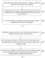
As shown in FIG. 1, it is a flow chart of a target object detection method provided by an embodiment of the present disclosure, the method is periodically executed, and as shown in FIG. 1, the method may include:
In S11, a target object is identified based on the first N frames of image data obtained within a current execution period, wherein N is a positive integer, and the N is less than the total number of frames of image data that can be obtained within the current execution period.
Exemplarily, the method can be applied to a variety of fields, such as traffic, monitoring, and the like. When the method is applied to the traffic field, the target object can be pedestrian(s), vehicle(s) or traffic sign(s) and the like; and when the method is applied to the monitoring field, the target object can be pedestrian(s), animal(s) and the like. The above embodiments are merely illustrative and are not intended to limit the present disclosure. For example, the target object can also be other objects with shapes and boundaries.
In S12, if the target object is identified, the target object is tracked based on the obtained image data within the remaining time period of the current execution period.
The remaining time period of the current execution period is a time period from the moment when the target object is identified to the termination of the current execution period.
The identified target object can be tracked by using a tracking algorithm, for example, the MOSSE (Minimum Output Sum of Squared Error) algorithm, wherein when the target object is tracked based on the MOSSE algorithm, the frames per second is usually greater than 1000, therefore, for typical universal 30 FPS (Frames Per Second) image data (for example, video streams), the corresponding image data are substantially the same within a relatively short period of time, therefore the tracking accuracy of the target object can be effectively guaranteed. It should be noted that the MOSSE algorithm is the prior art and thus is not described here again.
In the above technical solution, only the first N frames of image data participate in the calculation process of the target object identification within the current execution period, when the target object is identified, the identified target object is tracked within the remaining time period of the current execution period, so that the data calculation amount can be effectively reduced, and the use range of the target object detection method can be broadened. Moreover, since the image data within one execution period are basically similar, by tracking the target data, the detection accuracy of the target object can be ensured while ensuring the detection instantaneity of the target object. Moreover, the method provided in the present disclosure is periodically executed, and the target object can be re-identified at the beginning of each execution period, and a new target object can also be found in real time, thereby further improving the tracking accuracy of the target object, and improving the detection accuracy of the target object.
In order to make it easier for those skilled in the art to understand the technical solutions provided by the embodiments of the present disclosure, each step in the above method is firstly described in detail below.
Optionally, N=1, that is to say, when the target object is identified based on the first N frames of image data obtained within the current execution period, the target object can be identified only based on the first frame image obtained within the current execution period, therefore the data calculation amount can be further reduced, the waste of resources caused by the target object detection can be avoided, and the instantaneity of the target object detection can be improved.
A target object identification model can be pre-trained, and the target object identification model is used for identifying the target object in the input image data. For example, the target object identification model can be trained by using a deep learning method, for example, the target object can be detected by an SSD (Single Shot MultiBox Detector) algorithm or a YOLO (You Only Look Once) algorithm. Exemplarily, a training image of the target object identification model can be marked according to the application scenario of the target object detection method. For example, when the target object detection method is applied to the traffic field, pedestrians, vehicles, traffic signs and the like in the training image can be marked, the number of training images can be set based on the accuracy of the target object identification model, and the higher the precision requirements of the target object identification model is, the greater the number of the training images can be set. The manner for training the model in the deep learning manner is the prior art and thus is not described herein again.
Therefore, after the target object identification model is pre-trained, only the first frame image needs to be input to the target object identification model, and then the target object in the image can be quickly and accurately identified, thereby effectively ensuring accuracy of target object identification, but also ensuring the efficiency of the target object identification and improving the instantaneity of the target object detection method.
When N is greater than 1, the identifying the target object based on the first N frames of image data obtained within the current execution period includes:
inputting a target image to the target object identification model, wherein the target image is initially the first frame image obtained within the current execution period;
if the target object is identified based on the target image, a step 12 can be directly executed; and
if the target object is not identified based on the target image, using the next frame image as the target image, and inputting the target image to the target object identification model, until the target object is identified or the first N frame images are input to the target object identification model.
N can be set according to the actual usage scenario. Exemplarily, when N is 3, the first frame image obtained within the current execution period is input as the target image to the target object identification model, if the target object is not identified based on the target image, the next frame image (at this time, it is a second frame image) obtained within the current execution period is input as the target image to the target object identification model again, if the target object is identified based on the target image, the step 12 is executed, if the target object is not identified based on the target image, the next frame image (at this time, it is a third frame image) obtained within the current execution period is input as the target image to the target object identification model again, if the target object is identified based on the target image, the step 12 is executed, if the target object is not identified based on the target image, the first three frame images are all input to the target object identification model, and this time, it can be determined that the target object is not identified within the current execution period.
Therefore, by means of the above technical solution, the target object of the current execution period can be identified, and when the target object is identified, the target object is directly tracked, thereby effectively reducing the data calculation amount required for identifying the target object within the current execution period, and furthermore, the target object is detected via multiple frame images, the detection accuracy of the target object can also be effectively ensured.
Optionally, as shown in FIG. 2, it is a flow chart of a target object detection method provided by another embodiment of the present disclosure, and as shown in FIG. 2, the method further includes:
In S21, if the target object is not identified, entering a sleep state until the termination of the current execution period.
The time length of the execution period is generally short. Optionally, the time length of the execution period is determined in the following manner: the greater the moving speed of a collection apparatus of the image data is, the shorter the time length of the execution period is. For example, taking a vehicle-mounted system as an example, the collection apparatus of the image data can be a camera apparatus installed on the vehicle, and the moving speed thereof is the moving speed of the current vehicle. For example, for the image data of 30 FPS, the time length range of the execution period can be [0.33 S, 3 S]. For example, when the current moving speed is greater, the time length of the execution period can be set as 0.5 S, and when the moving speed of the current vehicle is smaller, the time length of the execution period can be set as 2 S. It should be noted that the foregoing description is only exemplary illustration, and the time length of the execution period can be set according to the actual usage scenario, which is not limited in the present disclosure.
In the present embodiment, if the target object is not identified, there are two possible situations as follows:
1) there is no target object needing to be identified in the first N frames of image data obtained within the current execution period; and
2) the target object exists in the first N frames of image data obtained within the current execution period, but has not been identified yet.
Since the time length of the execution period is short, and the target object detection method provided by the present disclosure is periodically executed, for both situations 1) and 2) mentioned above, the sleep state can be enter when the target object is not identified, that is, it is unnecessary to perform a corresponding operation within the current execution period, and the method is executed again until within the next execution period. Therefore, by adoption of the above technical solution, when the target object is not identified, the sleep state is entered, so that the waste of resources caused by unnecessary calculation can be effectively avoided, and the method can be re-executed until the arrival of the next execution period, thereby ensuring the instantaneity of the target object detection and guaranteeing the user experience.
Optionally, as shown in FIG. 3, it is a flow chart of a target object detection method provided by another embodiment of the present disclosure, and as shown in FIG. 3, the method further includes:
In S31, in the process of tracking the target object based on the obtained image data, if tracking failure occurs, entering the sleep state until the termination of the current execution period.
As described above, if the target object is identified within the current execution period, the target object is tracked based on the obtained image data within the remaining time period of the current execution period. However, the target object may leave the field of view corresponding to the image data within the current execution period, and at this time, the tracking failure can be determined. In addition, the tracking algorithm itself may also be unable to track the target object, and at this time, the tracking failure can also be determined.
Within the current execution period, when the tracking failure occurs in the process of tracking the target object, the sleep state is entered, and the method is re-executed until the arrival of the next execution period. Since the execution period is relatively short, when the sleep state is entered in the case of the tracking failure, no obvious delay occurs during the target object detection, the calculation resources can be saved, and the resource utilization rate can be improved.
In addition, in the method, by performing target object identification on a part of image data within the current execution period, the data calculation amount can be effectively reduced, so that the target object detection method can be applied to a system having high instantaneity requirements with relatively insufficient calculating capability. Optionally, the method can be applied to an embedded platform. By this approach, the calculation load can be effectively reduced, so that the phenomenon that the performance of an embedded system is seriously degraded due to the high calculation amount required when the method in the prior art is directly applied to the embedded platform can be avoided, and the stability of the embedded system can be ensured, the use range of the method is effectively broadened accordingly.
The present disclosure further provides a target object detection apparatus, as shown in FIG. 4, the apparatus 10 including:
an identifying module 100, configured to identify a target object based on the first N frames of image data obtained within a current execution period, wherein N is a positive integer, and N is less than the total number of frames of image data that can be obtained within the current execution period; and
a tracking module 200 configured to, if the target object is identified, track the target object based on the obtained image data within the remaining time period of the current execution period.
Optionally, the tracking module is further configured to:
if the target object is not identified, enter a sleep state until the termination of the current execution period.
Optionally, the tracking module is further configured to:
in the process of tracking the target object based on the obtained image data, if tracking failure occurs, enter the sleep state until the termination of the current execution period.
Optionally, N=1.
Optionally, the time length of the execution period is determined in the following manner:
the greater the moving speed of a collection apparatus of the image data is, the shorter the time length of the execution period is.
Optionally, the method is applied to an embedded platform.
With regard to the apparatus in the above embodiment, the specific manners of the various modules to execute operations have been described in detail in the embodiment relating to the method, and thus are not explained in detail herein.
FIG. 5 is a block diagram of an electronic device 700 shown according to an exemplary embodiment. As shown in FIG. 5, the electronic device 700 may include a processor 701 and a memory 702. The electronic device 700 may also include one or more of a multimedia component 703, an input/output (I/O) interface 704 and a communication component 705.
The processor 701 is configured to control the overall operation of the electronic device 700 to complete all or a part of steps in the foregoing target object detection method. The memory 702 is configured to store various types of data to support operations at the electronic device 700, for example, these data may include instructions for operating any application program or method on the electronic device 700, and related data of the application program, for example, contact data, sent and received messages, pictures, audio, videos, and so on. The memory 702 can be implemented by any type of volatile or non-volatile storage device or a combination thereof, such as a Static Random Access Memory (referred to as SRAM), an Electrically Erasable Programmable Read-Only Memory (referred to as EEPROM), an Erasable Programmable Read-Only Memory (referred to as EPROM), a Programmable Read-Only Memory (referred to as PROM), a Read-Only Memory (referred to as ROM), a magnetic memory, a flash memory, a magnetic disk or an optical disk. The multimedia component 703 may include a screen and an audio component. The screen can be, for example, a touch screen, and the audio component is configured to output and/or input an audio signal. For example, the audio component may include a microphone for receiving an external audio signal. The received audio signal can be further stored in the memory 702 or sent by the communication component 705. The audio component further includes at least one loudspeaker for outputting the audio signal. The I/O interface 704 provides an interface between the processor 701 and other interface modules. The other interface modules can be keyboards, mice, buttons, and the like. These buttons may be virtual buttons or physical buttons. The communication component 705 is used for wired or wireless communication between the electronic device 700 and other devices. The wireless communication includes, such as Wi-Fi, Bluetooth, Near Field Communication (referred to as NFC), 2G, 3G, 4G, NB-IOT, eMTC, or other 5G and the like, or the combination of one or more of them, and it is not limited herein. Therefore, the corresponding communication component 705 may include: a Wi-Fi module, a Bluetooth module, an NFC module, and the like.
In an exemplary embodiment, the electronic device 700 may be implemented by one or more Application Specific Integrated Circuits (referred to as ASICs), Digital Signal Processor (referred to as DSP), Digital Signal Processing Device (referred to as DSPD), Programmable Logic Device (referred to as PLD), Field Programmable Gate Array (referred to as FPGA), controllers, microcontrollers, microprocessors or other electronic components, and is configured to execute the target object detection method described above.
In another exemplary embodiment, a computer readable storage medium including program instructions is further provided, and the program instructions implement the steps of the target object detection method described above when being executed by the processor. For example, the computer readable storage medium can be the above memory 702 including the program instructions, and the program instructions can be executed by the processor 701 of the electronic device 700 to complete the target object detection method described above.
In another exemplary embodiment, a computer program product is further provided, the computer program product includes a computer program executable by a programmable apparatus, and the computer program has a code portion for executing the target object detection method described above when being executed by the programmable apparatus.
FIG. 6 is a block diagram of an electronic device 1900 shown according to an exemplary embodiment. For example, electronic device 1900 can be provided as a server. Referring to FIG. 6, the electronic device 1900 includes a processor 1922, which may be one or more, and a memory 1932 for storing a computer program executed by the processor 1922. The computer program stored in the memory 1932 may include one or more modules, wherein each corresponds to a group of instructions. In addition, the processor 1922 can be configured to execute the computer program to execute the target object detection method described above.
Additionally, the electronic device 1900 may further include a power supply component 1926 and a communication component 1950, the power supply component 1926 may be configured to execute power supply management of the electronic device 1900, and the communication component 1950 may be configured to achieve the communication of the electronic device 1900, for example, wired or wireless communication. Additionally, the electronic device 1900 may further include an input/output (I/O) interface 1958. The electronic device 1900 can operate an operating system stored in the memory 1932, such as Windows Server™, Mac OS X™, Unix™, Linux™, and the like.
In another exemplary embodiment, a computer readable storage medium including program instructions are further provided, and the program instructions implement the steps of the target object detection method described above when being executed by the processor. For example, the computer readable storage medium can be the above memory 1932 including the program instructions, and the program instructions can be executed by the processor 1922 of the electronic device 1900 to complete the target object detection method described above.
In another exemplary embodiment, a computer program product is further provided, the computer program product includes a computer program executable by a programmable apparatus, and the computer program has a code portion for executing the target object detection method described above when being executed by the programmable apparatus.
The preferred embodiments of the present disclosure have been described in detail above with reference to the drawings. However, the present disclosure is not limited to the specific details in the above embodiments, various simple modifications can be made to the technical solutions of the present disclosure within the scope of the technical concept of the present disclosure, and these simple variations are all within the protection scope of the present disclosure.
It should be further noted that the specific technical features described in the above specific embodiments can be combined in any suitable manner without contradiction. In order to avoid unnecessary repetition, various possible combinations are not additionally illustrated in the present disclosure.
In addition, various different embodiments of the present disclosure can be randomly combined, and the combinations should also be regarded as the contents disclosed by the present disclosure as long as not deviating from the spirit of the present disclosure.

Claims (12)

What is claimed is:
1. A target object detection method comprising:
identifying a target object based on first N frames of image data obtained within a current execution period, wherein N is a positive integer, and N is less than the total number of frames of image data that can be obtained within the current execution period; and
if the target object is identified, tracking the target object based on the obtained image data within the remaining time period of the current execution period; and
in the process of tracking the target object based on the obtained image data, if tracking failure occurs, entering a sleep state until a termination of the current execution period;
wherein the target object detection method is periodically executed.
2. The method according to claim 1, wherein N=1.
3. The method according to claim 1, wherein a time length of the current execution period is determined in the following manner:
the greater a moving speed of a collection apparatus of the obtained image data is, the shorter the time length of the current execution period is.
4. The method according to claim 1, wherein the method is applied to an embedded platform.
5. A non-transitory computer readable storage medium, wherein a computer program is stored thereon, and the computer program implements the steps of the method of claim 1.
6. An electronic device, comprising:
a memory, wherein a computer program is stored thereon; and
a processor, configured to execute the computer program in the memory to implement the steps of the method of claim 1.
7. A target object detection method comprising:
identifying a target object based on first N frames of image data obtained within a current execution period, wherein N is a positive integer, and N is less than the total number of frames of image data that can be obtained within the current execution period; and
if the target object is not identified, entering a sleep state until a termination of the current execution period;
wherein the target object detection method is periodically executed.
8. The method according to claim 7, wherein N=1.
9. The method according to claim 7, wherein a time length of the current execution period is determined in the following manner:
the greater a moving speed of a collection apparatus of the obtained image data is, the shorter the time length of the current execution period is.
10. The method according to claim 7, wherein the method is applied to an embedded platform.
11. A non-transitory computer readable storage medium, wherein a computer program is stored thereon, and the computer program implements the steps of a method according to claim 7 when being executed by a processor.
12. An electronic device, comprising:
a memory, wherein a computer program is stored thereon; and
a processor, configured to execute the computer program in the memory to implement the steps of a method according to claim 7.
US16/564,507 2019-04-10 2019-09-09 Target object detection method, readable storage medium, and electronic device Active 2039-10-07 US11037301B2 (en)

Applications Claiming Priority (2)

Application Number Priority Date Filing Date Title
CN201910285913.5 2019-04-10
CN201910285913.5A CN110110604A (en) 2019-04-10 2019-04-10 Target object detection method, device, readable storage medium storing program for executing and electronic equipment

Publications (2)

Publication Number Publication Date
US20200327677A1 US20200327677A1 (en) 2020-10-15
US11037301B2 true US11037301B2 (en) 2021-06-15

Family

ID=67484015

Family Applications (1)

Application Number Title Priority Date Filing Date
US16/564,507 Active 2039-10-07 US11037301B2 (en) 2019-04-10 2019-09-09 Target object detection method, readable storage medium, and electronic device

Country Status (2)

Country Link
US (1) US11037301B2 (en)
CN (1) CN110110604A (en)

Families Citing this family (4)

* Cited by examiner, † Cited by third party
Publication number Priority date Publication date Assignee Title
CN111710028B (en) * 2020-05-27 2023-06-30 北京东软医疗设备有限公司 Three-dimensional contrast image generation method and device, storage medium and electronic equipment
CN112562159B (en) * 2020-11-24 2022-10-14 恒安嘉新(北京)科技股份公司 Access control method and device, computer equipment and storage medium
CN112712051A (en) * 2021-01-12 2021-04-27 腾讯科技(深圳)有限公司 Object tracking method and device, computer equipment and storage medium
CN112991393A (en) * 2021-04-15 2021-06-18 北京澎思科技有限公司 Target detection and tracking method and device, electronic equipment and storage medium

Citations (11)

* Cited by examiner, † Cited by third party
Publication number Priority date Publication date Assignee Title
US20080231564A1 (en) * 2007-03-16 2008-09-25 Sony Corporation Display apparatus and method for controlling the same
US20110158475A1 (en) * 2009-07-17 2011-06-30 Kabushiki Kaisha Topcon Position Measuring Method And Position Measuring Instrument
US20130194438A1 (en) * 2011-08-18 2013-08-01 Qualcomm Incorporated Smart camera for sharing pictures automatically
US20130201344A1 (en) * 2011-08-18 2013-08-08 Qualcomm Incorporated Smart camera for taking pictures automatically
US20160063344A1 (en) * 2014-08-27 2016-03-03 International Business Machines Corporation Long-term static object detection
US20170053409A1 (en) * 2015-08-18 2017-02-23 Canon Kabushiki Kaisha Information processing apparatus, information processing method and program
CN108307116A (en) 2018-02-07 2018-07-20 腾讯科技(深圳)有限公司 Image capturing method, device, computer equipment and storage medium
US20180213166A1 (en) * 2017-01-25 2018-07-26 Samsung Electronics Co., Ltd. Electronic device and method for capturing image in electronic device
CN108596955A (en) 2018-04-25 2018-09-28 Oppo广东移动通信有限公司 A kind of image detecting method, image detection device and mobile terminal
US10176683B2 (en) * 2014-09-18 2019-01-08 Honeywell International Inc. Virtual panoramic thumbnail to summarize and visualize video content in video surveillance and in connected home business
US20200042010A1 (en) * 2018-07-31 2020-02-06 Casio Computer Co., Ltd. Autonomous mobile apparatus, autonomous movement method, and non-transitory recording medium

Patent Citations (11)

* Cited by examiner, † Cited by third party
Publication number Priority date Publication date Assignee Title
US20080231564A1 (en) * 2007-03-16 2008-09-25 Sony Corporation Display apparatus and method for controlling the same
US20110158475A1 (en) * 2009-07-17 2011-06-30 Kabushiki Kaisha Topcon Position Measuring Method And Position Measuring Instrument
US20130194438A1 (en) * 2011-08-18 2013-08-01 Qualcomm Incorporated Smart camera for sharing pictures automatically
US20130201344A1 (en) * 2011-08-18 2013-08-08 Qualcomm Incorporated Smart camera for taking pictures automatically
US20160063344A1 (en) * 2014-08-27 2016-03-03 International Business Machines Corporation Long-term static object detection
US10176683B2 (en) * 2014-09-18 2019-01-08 Honeywell International Inc. Virtual panoramic thumbnail to summarize and visualize video content in video surveillance and in connected home business
US20170053409A1 (en) * 2015-08-18 2017-02-23 Canon Kabushiki Kaisha Information processing apparatus, information processing method and program
US20180213166A1 (en) * 2017-01-25 2018-07-26 Samsung Electronics Co., Ltd. Electronic device and method for capturing image in electronic device
CN108307116A (en) 2018-02-07 2018-07-20 腾讯科技(深圳)有限公司 Image capturing method, device, computer equipment and storage medium
CN108596955A (en) 2018-04-25 2018-09-28 Oppo广东移动通信有限公司 A kind of image detecting method, image detection device and mobile terminal
US20200042010A1 (en) * 2018-07-31 2020-02-06 Casio Computer Co., Ltd. Autonomous mobile apparatus, autonomous movement method, and non-transitory recording medium

Non-Patent Citations (1)

* Cited by examiner, † Cited by third party
Title
Office Action for corresponding Chinese Patent Application No. 201910285913.5, dated Sep. 25, 2020.

Also Published As

Publication number Publication date
US20200327677A1 (en) 2020-10-15
CN110110604A (en) 2019-08-09

Similar Documents

Publication Publication Date Title
US11037301B2 (en) Target object detection method, readable storage medium, and electronic device
US11443523B2 (en) Dynamic obstacle point cloud annotating method and apparatus, device and readable medium
CN109240576B (en) Image processing method and device in game, electronic device and storage medium
CN111369590A (en) Multi-target tracking method and device, storage medium and electronic equipment
CN101465955B (en) Method and apparatus for updating background
CN113011323B (en) Method for acquiring traffic state, related device, road side equipment and cloud control platform
US10111033B2 (en) GIS based compression and reconstruction of GPS data for transmission from a vehicular edge platform to the cloud
CN110059623B (en) Method and apparatus for generating information
CN115616937B (en) Automatic driving simulation test method, device, equipment and computer readable medium
US20230278587A1 (en) Method and apparatus for detecting drivable area, mobile device and storage medium
CN110688873A (en) Multi-target tracking method and face recognition method
CN110287817B (en) Target recognition and target recognition model training method and device and electronic equipment
CN109740442B (en) Positioning method, positioning device, storage medium and electronic equipment
CN112558036B (en) Method and device for outputting information
KR102473272B1 (en) Target tracking method and device
CN109270566B (en) Navigation method, navigation effect testing method, device, equipment and medium
CN114429631B (en) Three-dimensional object detection method, device, equipment and storage medium
CN112507957B (en) Vehicle association method and device, road side equipment and cloud control platform
CN111445499B (en) Method and device for identifying target information
CN110348374B (en) Vehicle detection method and device, electronic equipment and storage medium
CN109885475B (en) Page conversion rate calculation method, device, computer equipment and storage medium
JP2014185876A (en) Control method for portable information terminal, control program and portable information terminal
CN114049615B (en) Traffic object fusion association method and device in driving environment and edge computing equipment
CN109492695B (en) Sample processing method and device for data modeling, electronic equipment and readable medium
CN112765196B (en) Data processing and data recognition method and device, electronic equipment and storage medium

Legal Events

Date Code Title Description
FEPP Fee payment procedure

Free format text: ENTITY STATUS SET TO UNDISCOUNTED (ORIGINAL EVENT CODE: BIG.); ENTITY STATUS OF PATENT OWNER: LARGE ENTITY

AS Assignment

Owner name: NEUSOFT CORPORATION, CHINA

Free format text: ASSIGNMENT OF ASSIGNORS INTEREST;ASSIGNORS:YANG, MENGHUI;ZHANG, MICHAEL;REEL/FRAME:051410/0143

Effective date: 20190517

STPP Information on status: patent application and granting procedure in general

Free format text: NON FINAL ACTION MAILED

STPP Information on status: patent application and granting procedure in general

Free format text: RESPONSE TO NON-FINAL OFFICE ACTION ENTERED AND FORWARDED TO EXAMINER

STPP Information on status: patent application and granting procedure in general

Free format text: NOTICE OF ALLOWANCE MAILED -- APPLICATION RECEIVED IN OFFICE OF PUBLICATIONS

STPP Information on status: patent application and granting procedure in general

Free format text: PUBLICATIONS -- ISSUE FEE PAYMENT RECEIVED

STPP Information on status: patent application and granting procedure in general

Free format text: PUBLICATIONS -- ISSUE FEE PAYMENT VERIFIED

STCF Information on status: patent grant

Free format text: PATENTED CASE