US11036588B2 - Redundancy between physical and virtual entities in hyper-converged infrastructures - Google Patents
Redundancy between physical and virtual entities in hyper-converged infrastructures Download PDFInfo
- Publication number
- US11036588B2 US11036588B2 US16/689,117 US201916689117A US11036588B2 US 11036588 B2 US11036588 B2 US 11036588B2 US 201916689117 A US201916689117 A US 201916689117A US 11036588 B2 US11036588 B2 US 11036588B2
- Authority
- US
- United States
- Prior art keywords
- entity
- physical
- virtual
- configuration data
- physical entity
- Prior art date
- Legal status (The legal status is an assumption and is not a legal conclusion. Google has not performed a legal analysis and makes no representation as to the accuracy of the status listed.)
- Active, expires
Links
Images


Classifications
-
- G—PHYSICS
- G06—COMPUTING OR CALCULATING; COUNTING
- G06F—ELECTRIC DIGITAL DATA PROCESSING
- G06F11/00—Error detection; Error correction; Monitoring
- G06F11/07—Responding to the occurrence of a fault, e.g. fault tolerance
- G06F11/16—Error detection or correction of the data by redundancy in hardware
- G06F11/20—Error detection or correction of the data by redundancy in hardware using active fault-masking, e.g. by switching out faulty elements or by switching in spare elements
- G06F11/202—Error detection or correction of the data by redundancy in hardware using active fault-masking, e.g. by switching out faulty elements or by switching in spare elements where processing functionality is redundant
-
- G—PHYSICS
- G06—COMPUTING OR CALCULATING; COUNTING
- G06F—ELECTRIC DIGITAL DATA PROCESSING
- G06F11/00—Error detection; Error correction; Monitoring
- G06F11/07—Responding to the occurrence of a fault, e.g. fault tolerance
- G06F11/14—Error detection or correction of the data by redundancy in operations
- G06F11/1402—Saving, restoring, recovering or retrying
- G06F11/1415—Saving, restoring, recovering or retrying at system level
- G06F11/1435—Saving, restoring, recovering or retrying at system level using file system or storage system metadata
-
- G—PHYSICS
- G06—COMPUTING OR CALCULATING; COUNTING
- G06F—ELECTRIC DIGITAL DATA PROCESSING
- G06F11/00—Error detection; Error correction; Monitoring
- G06F11/07—Responding to the occurrence of a fault, e.g. fault tolerance
- G06F11/08—Error detection or correction by redundancy in data representation, e.g. by using checking codes
- G06F11/10—Adding special bits or symbols to the coded information, e.g. parity check, casting out 9's or 11's
- G06F11/1076—Parity data used in redundant arrays of independent storages, e.g. in RAID systems
- G06F11/1092—Rebuilding, e.g. when physically replacing a failing disk
-
- G—PHYSICS
- G06—COMPUTING OR CALCULATING; COUNTING
- G06F—ELECTRIC DIGITAL DATA PROCESSING
- G06F11/00—Error detection; Error correction; Monitoring
- G06F11/07—Responding to the occurrence of a fault, e.g. fault tolerance
- G06F11/14—Error detection or correction of the data by redundancy in operations
- G06F11/1479—Generic software techniques for error detection or fault masking
- G06F11/1482—Generic software techniques for error detection or fault masking using middleware or operating system [OS] functionalities
- G06F11/1484—Generic software techniques for error detection or fault masking using middleware or operating system [OS] functionalities involving virtual machines
-
- G—PHYSICS
- G06—COMPUTING OR CALCULATING; COUNTING
- G06F—ELECTRIC DIGITAL DATA PROCESSING
- G06F11/00—Error detection; Error correction; Monitoring
- G06F11/07—Responding to the occurrence of a fault, e.g. fault tolerance
- G06F11/16—Error detection or correction of the data by redundancy in hardware
- G06F11/20—Error detection or correction of the data by redundancy in hardware using active fault-masking, e.g. by switching out faulty elements or by switching in spare elements
- G06F11/2053—Error detection or correction of the data by redundancy in hardware using active fault-masking, e.g. by switching out faulty elements or by switching in spare elements where persistent mass storage functionality or persistent mass storage control functionality is redundant
- G06F11/2094—Redundant storage or storage space
-
- G—PHYSICS
- G06—COMPUTING OR CALCULATING; COUNTING
- G06F—ELECTRIC DIGITAL DATA PROCESSING
- G06F11/00—Error detection; Error correction; Monitoring
- G06F11/30—Monitoring
- G06F11/3003—Monitoring arrangements specially adapted to the computing system or computing system component being monitored
- G06F11/3006—Monitoring arrangements specially adapted to the computing system or computing system component being monitored where the computing system is distributed, e.g. networked systems, clusters, multiprocessor systems
-
- G—PHYSICS
- G06—COMPUTING OR CALCULATING; COUNTING
- G06F—ELECTRIC DIGITAL DATA PROCESSING
- G06F11/00—Error detection; Error correction; Monitoring
- G06F11/30—Monitoring
- G06F11/3003—Monitoring arrangements specially adapted to the computing system or computing system component being monitored
- G06F11/301—Monitoring arrangements specially adapted to the computing system or computing system component being monitored where the computing system is a virtual computing platform, e.g. logically partitioned systems
-
- G—PHYSICS
- G06—COMPUTING OR CALCULATING; COUNTING
- G06F—ELECTRIC DIGITAL DATA PROCESSING
- G06F2201/00—Indexing scheme relating to error detection, to error correction, and to monitoring
- G06F2201/815—Virtual
Definitions
- the present disclosure relates to computing environments, and more particularly to methods, techniques, and systems for providing redundancy between physical and virtual entities in a hyper-converged infrastructure.
- SDDCs software defined data centers
- networking, storage, processing, and security may be virtualized and delivered as a service
- hyper-converged infrastructure may refer to a rack-based system that combines compute, storage, and networking components into a single system to reduce data center complexity and increase scalability.
- the deployment, provisioning, configuration, and operation of the entire network infrastructure may be abstracted from hardware and implemented using software.
- the SDDC may include multiple clusters of physical servers and each cluster may execute SDDC components.
- the SDDC components may include monitoring and management applications/services corresponding to network virtualization, server virtualization, storage virtualization, and the like. Further, such components may rely on data replication and synchronization to maintain continuous system availability (also referred as high availability).
- FIG. 1A is a block diagram of an example system illustrating a physical to virtual redundancy module to provide redundancy between physical and virtual entities;
- FIG. 1B is the block diagram of the example system of FIG. 1A , depicting an example physical to virtual redundancy table to provide redundancy between the physical entity and the equivalent virtual entity;
- FIG. 2 shows an example physical to virtual redundancy table corresponding to a compute node in a hyper-converged infrastructure
- FIG. 3 is an example flow diagram illustrating providing redundancy between physical and virtual entities in a hyper-converged infrastructure
- FIG. 4 is an example flow diagram illustrating dynamically updating a physical to virtual redundancy table based on a change in configuration data associated with a physical entity or an equivalent virtual entity;
- FIG. 5 is an example flow diagram illustrating designating an equivalent virtual entity as a primary entity to perform functions of a physical entity during an event of failure of the physical entity;
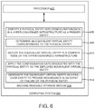
- FIG. 6 is a block diagram of an example computing system including a non-transitory computer-readable storage medium, storing instructions to provide redundancy between physical and virtual entities in a hyper-converged infrastructure.
- Examples described herein may provide an enhanced computer-based and network-based method, technique, and system for providing redundancy between physical and virtual entities in software defined data centers (SDDCs) with hyper-converged infrastructure.
- An SDDC may include multiple clusters of physical servers and each cluster may be a policy-based resource container with specific availability and performance attributes that combines compute (e.g., vSphere of VMware®), storage (vSAN of VMware®), and networking (e.g., NSX of VMware®) into a single consumable entity via different applications.
- each cluster may correspond to one workload domain of the SDDC.
- the workload domain may be deployed in a virtual server rack, which may include the cluster of physical components or physical servers located across a plurality of physical racks.
- the workload domain may be deployed in a single physical rack.
- the hyper-converged infrastructure may combine a virtualization platform such as a hypervisor, virtualized software-defined storage, and virtualized networking in an SDDC deployment.
- the workload domains may rely on data replication and synchronization to maintain continuous system availability, which may be referred as high availability.
- the hyper-converged infrastructure may include physical entities (e.g., network devices such as routers, software-defined wide area network (SD-WAN) components, and the like), which may be deployed as single elements without high availability.
- physical entities e.g., network devices such as routers, software-defined wide area network (SD-WAN) components, and the like
- SD-WAN software-defined wide area network
- branch offices may not be able to offer redundancy of such physical entities because of constraints such as cost, maintenance, and the like.
- small and medium scale deployments may include single point of failures when the physical entity (e.g., without high availability) fails in the hyper-converged infrastructure.
- Some examples may provide a redundancy between physical entities and between virtual entities in the hyper-converged infrastructure.
- there may be deployments with the combination of the virtual and physical entities in the hyper-converged infrastructure.
- providing redundancy between the virtual and physical entities may be challenging to avoid single point of failures.
- Examples described herein may provide redundancy between physical and virtual entities in a hyper-converged infrastructure. Examples described herein may provide a physical to virtual redundancy module in a management node of the hyper-converged infrastructure.
- the physical to virtual redundancy module may identify a physical entity with configuration data in the hyper-converged infrastructure as a primary entity, determine an equivalent virtual entity corresponding to the physical entity, and deploy the equivalent virtual entity in a compute node of the hyper-converged infrastructure. Further, the physical to virtual redundancy module may apply the configuration data associated with the physical entity to the deployed equivalent virtual entity and designate the equivalent virtual entity as a fail-over entity to provide redundancy in an event of failure of the physical entity.
- examples described herein may provide robust and flexible mechanism to offer redundancy between the physical to virtual entities in the hyper-converged infrastructure to avoid single point of failures. Further, examples described herein may provide redundancy in small to medium scale deployments without additional hardware component being installed.
- FIG. 1A is a block diagram of an example system 100 illustrating a physical to virtual redundancy module 110 to provide redundancy between physical and virtual entities.
- Example system 100 may represent a SDDC with hyper-converged infrastructure.
- the SDDC may be a data storage facility in which infrastructure elements such as networking, storage, central processing unit (CPU), security and the like can be virtualized and delivered as a service in cloud computing environments.
- Cloud computing may be based on the deployment of physical resources across a network, virtualizing the physical resources into virtual resources, and provisioning the virtual resources in SDDCs for use across cloud computing services and applications. Further, SDDCs can be implemented using a hyperconverged infrastructure.
- Hyperconverged infrastructure may combine a virtualization platform such as a hypervisor, virtualized software-defined storage, and virtualized networking in an SDDC deployment.
- An example platform to deploy and manage the SDDCs may include VMware Cloud FoundationTM (VCF), which is commercially available from VMware.
- VCF VMware Cloud FoundationTM
- Example system 100 may include remote office and branch office (ROBO) architecture having a central office (e.g., management node 104 ) and multiple branch offices 102 A to 102 C.
- Example management node 104 may execute a centralized management application to centrally manage branch offices 102 A to 102 C.
- management node 104 and branch offices 102 A to 102 C may be distributed across multiple sites (e.g., separate geographical locations).
- management node 104 may be implemented in a computing device, either virtual or physical, and is communicatively coupled to branch offices 102 A- 102 C via a network 116 (e.g., Wi-Fi, WiMAX, local area network (LAN), wide area network (WAN), metropolitan area network, Internet network, fixed wireless network, a wireless LAN, wireless WAN, personal area network (PAN), virtual private network (VPN), intranet, SD-WAN, or the like).
- a network 116 e.g., Wi-Fi, WiMAX, local area network (LAN), wide area network (WAN), metropolitan area network, Internet network, fixed wireless network, a wireless LAN, wireless WAN, personal area network (PAN), virtual private network (VPN), intranet, SD-WAN, or the like.
- branch offices 102 A to 102 C may include respective workload domains 112 A to 112 C.
- each workload domain (e.g., 112 A to 112 C) may include a set of servers that are managed by management node 104 .
- each workload domain may be a policy-based resource container with specific availability and performance attributes that combines compute, storage, and networking into a single consumable entity via different applications.
- system 100 may include multiple physical entities.
- a physical entity may refer to any entity that is available as a physical component as well as a virtual component.
- the physical entities may be network devices to manage network traffic to the Internet and vice-versa.
- Example physical entity may be a router (e.g., router 106 A, 106 B, 106 C, or 106 D) as shown in FIG. 1A ), a software-defined wide area network (SD-WAN) component, a firewall device, a network address translator, or the like.
- physical entity e.g., router 106 B
- management node 104 may include a management module 108 and a physical to virtual redundancy module 110 .
- management node 104 may include a processor 118 and a memory 120 coupled to processor 118 .
- Memory 120 may include management module 108 and physical to virtual redundancy module 110 to provide redundancy between the physical and virtual entities.
- management module 108 and physical to virtual redundancy module 110 can be implemented as a single component.
- management module 108 may communicate with physical to virtual redundancy module 110 when a physical to virtual redundancy is required for any physical entity corresponding to branch offices 102 A to 102 C.
- the redundancy can be provided to a physical entity for which an equivalent software version (i.e., an equivalent software entity or an equivalent virtual entity) is available.
- physical to virtual redundancy module 110 may receive such requests from management module 108 to provide specific physical to virtual redundancy. Upon receiving such a request, physical to virtual redundancy module 110 may track the physical entities (i.e., single physical networking components) corresponding to a branch office (e.g., branch office 102 A).
- physical to virtual redundancy module 110 may identify router 106 B (e.g., herein after referred to as physical entity 106 B) upon receiving a request to create physical to virtual redundancy for physical entity 106 B.
- physical to virtual redundancy module 110 may identify physical entity 1068 with configuration data as a primary entity. Further, physical to virtual redundancy module 110 may determine an equivalent virtual entity 122 corresponding to physical entity 1068 .
- physical to virtual redundancy module 110 may deploy equivalent virtual entity 122 in a compute node associated with workload domain 112 A.
- Example compute node may be a virtual machine, a physical server, and the like. Also, physical to virtual redundancy module 110 may apply the configuration data associated with physical entity 1068 to deployed equivalent virtual entity 122 .
- physical entity router 106 B and the compute node may be implemented as part of workload domain 112 A of branch office 102 A of the hyper-converged infrastructure.
- physical to virtual redundancy module 110 may designate equivalent virtual entity 122 as a fail-over entity to provide redundancy in an event of failure of physical entity 106 B.
- physical entity 106 B may act as an active entity while equivalent virtual entity 122 may act as a standby entity.
- physical to virtual redundancy module 110 may detect a failure of physical entity 106 B.
- the failure of physical entity 106 B may be detected by running a probing mechanism at defined intervals.
- physical to virtual redundancy module 110 may designate equivalent virtual entity 122 as the primary entity and apply the network bring up configurations to equivalent virtual entity 122 to perform functions of physical entity 1068 .
- equivalent virtual entity 122 may become active.
- physical to virtual redundancy module 110 may detect that physical entity 1068 is back from the failure by regularly probing for status of physical entity 1068 .
- physical to virtual redundancy module 110 may designate equivalent virtual entity 122 as the fail-over entity via isolating equivalent virtual entity 122 from network 116 and designate physical entity 1068 as the primary entity.
- physical to virtual redundancy module 110 may track a change in the configuration data associated with equivalent virtual entity 122 while equivalent virtual entity 122 is acting as the primary entity. Further, physical to virtual redundancy module 110 may apply the change in the configuration data to physical entity 106 B that is designated as the primary entity when physical entity 106 B is back from the failure.
- system 100 may include a management switch 114 connected to network 116 .
- management switch 114 may facilitate the imaging of the compute nodes in workload domains 112 A to 112 C, copy required images to a local datastore, and manage the compute nodes and the physical entities of branch offices 102 A to 102 C.
- physical to virtual redundancy module 110 may perform synchronization of the configuration data, apply network connectivity configurations for equivalent virtual entity 122 , and/or image of the compute node (e.g., the physical server) via an out of band (OOB) management network via management switch 114 .
- OOB out of band
- FIG. 1B is the block diagram of the example system 100 of FIG. 1A , depicting an example physical to virtual redundancy table 154 to provide redundancy between physical entity 106 B and equivalent virtual entity 122 .
- workload domain 112 A may include multiple servers 152 A to 152 C with software-defined networking (SDN).
- SDN software-defined networking
- equivalent virtual entity 122 may be deployed on server 152 A or on a virtual machine running on server 152 A.
- management module 108 may monitor branch office 102 A to track the physical entities (e.g., router 106 B) along with associated metadata and also poll the corresponding configuration data. Further, management module 108 may handover the metadata and the configuration data to physical to virtual redundancy module 110 to populate or build physical to virtual redundancy table 154 with the metadata and the configuration data. Example physical to virtual redundancy table 154 is depicted in FIG. 3 .
- physical to virtual redundancy module 110 may communicate to one of servers (e.g., server 152 A) and deploy equivalent virtual entity 122 of physical entity 1068 on server 152 A using physical to virtual redundancy table 154 .
- physical to virtual redundancy module 110 may apply the configuration data associated with the physical entity to deployed equivalent virtual entity 122 using the physical to virtual redundancy table 154 .
- equivalent virtual entity 122 may be in passive mode and physical entity 1068 may be in active mode.
- physical to virtual redundancy module 110 may monitor the physical entity 106 B to detect a failure of physical entity 106 B. Upon detecting the failure, equivalent virtual entity 122 may become active and carry over the corresponding functions of physical entity 1068 (e.g., routing traffic to the Internet and vice-versa).
- physical to virtual redundancy module 110 may track a change in the configuration data associated with equivalent virtual entity 122 when equivalent virtual entity 122 is active or configured as the primary entity. Further, physical to virtual redundancy module 110 may update physical to virtual redundancy table 154 to reflect the change in the configuration data associated with equivalent virtual entity 122 . Further in operation, physical to virtual redundancy module 110 may apply the change in the configuration data to physical entity 106 B using the physical to virtual redundancy module 110 when physical entity 1068 is back from the failure and becomes active.
- a trigger may be generated to notify physical to virtual redundancy module 110 regarding the change in the configuration data via management module 108 .
- physical to virtual redundancy module 110 may update physical to virtual redundancy table 154 to reflect the change in the configuration data.
- virtual redundancy module 110 may make equivalent virtual entity 122 and apply delta configuration changes to physical entity 106 B using physical to virtual redundancy table 154 .
- physical to virtual redundancy module 110 may track a change in the configuration data associated with the physical entity or equivalent virtual entity 122 that is designated as the primary entity, and update physical to virtual redundancy table 154 to reflect the change in the configuration data. Further, physical to virtual redundancy module 110 may maintain physical to virtual redundancy table 154 such that the configuration data of the physical entity 106 B and equivalent virtual entity 122 may be identical. Also, networking connectivity configurations of equivalent virtual component 122 to the outside world can be taken care by physical to virtual redundancy module 110 . Also, physical to virtual redundancy module 110 may maintain synchronization of the configuration data, apply network connectivity configurations for virtual entity 122 , image of the servers via OOB management network corresponding to management switch 114 .
- the functionalities described in FIGS. 1A and 1B in relation to instructions to implement functions of management module 108 , physical to virtual redundancy module 110 , and any additional instructions described herein in relation to the storage medium, may be implemented as engines or modules including any combination of hardware and programming to implement the functionalities of the modules or engines described herein.
- the functions of management module 108 and physical to virtual redundancy module 110 may also be implemented by a respective processor.
- the processor may include, for example, one processor or multiple processors included in a single device or distributed across multiple devices.
- management module 108 and physical to virtual redundancy module 110 may be a software entity residing in a central management station such as management node 104 , a software-defined datacenter (SDDC) manager, a next generation VMware cloud foundation (VCF) central management orchestrator, or the like.
- SDDC software-defined datacenter
- VCF VMware cloud foundation
- FIG. 2 shows an example physical to virtual redundancy table (e.g., physical to virtual redundancy table 154 of FIG. 1B ) corresponding to a branch office 102 A of FIGS. 1A and 1B in a hyper-converged infrastructure.
- physical to virtual redundancy table 154 may be build corresponding to branch office 102 A and may include metadata and configuration data associated with the physical entities (i.e., single node physical entities) associated with branch office 102 A.
- Example physical to virtual redundancy table 154 may include different columns such as a physical entity identifier 202 , a type of a physical entity 204 , a software version 206 , configuration data 208 , an availability of equivalent virtual entity 210 , a type of virtual entity 212 , a source of the virtual entity 214 , and a status of high availability 216 .
- Physical entity identifier 202 may depict identifiers of the physical entities associated with branch office 102 A.
- Type of a physical entity 204 may depict physical entities' type such as a router, SD-WAN, and the like.
- Software version 206 may provide current software version being run on the physical entities.
- Configuration data 208 may depict configuration information of the physical entities.
- Availability of equivalent virtual entity 210 may depict information about availability of the equivalent virtual entities corresponding to the physical entities.
- Type of virtual entity 212 may depict the type of the virtual entities such as open virtualization format (OVF), open virtual appliance (OVA), and the like.
- availability of the equivalent virtual entities may be dynamically determined or manually entered. For example, based on the type of the virtual entities, the equivalent virtual entities may be dynamically determined by developing scripts.
- source of the virtual entity 214 may provide information regarding the source that provides the virtual entities.
- Status of high availability 216 may provide information whether high availability of the physical entities can be provided or not.
- the administrator may have flexibility to exclude any specific physical entity that may not require redundancy from physical to virtual redundancy table 154 . Also, when there is no equivalent or compatible virtual entity for the particular physical entity, the physical entity may be excluded from redundancy automatically. For example, as shown in third row of physical to virtual redundancy table 154 , a physical entity ‘arista router’ may not have an equivalent virtual entity. Thus, the ‘arista router’ may be excluded from providing redundancy.
- FIG. 3 is an example flow diagram 300 for providing redundancy between physical and virtual entities in a hyper-converged infrastructure.
- a physical entity with configuration data may be identified in a hyper-converged infrastructure as a primary entity.
- an equivalent virtual entity corresponding to the physical entity may be determined.
- the equivalent virtual entity may be deployed in a compute node (e.g., a virtual machine or server) of the hyper-converged infrastructure.
- the configuration data associated with the physical entity may be applied to the deployed equivalent virtual entity.
- the equivalent virtual entity may be designated as a fail-over entity to provide redundancy in an event of failure of the physical entity.
- FIG. 4 is an example flow diagram 400 for dynamically updating a physical to virtual redundancy table based on a change in configuration data associated with a physical entity or an equivalent virtual entity.
- the physical entity with the configuration data may be identified in a hyper-converged infrastructure as a primary entity.
- a physical to virtual redundancy table including metadata and the configuration data associated with the physical entity may be built and maintained.
- a check may be made to determine whether the physical entity is the primary entity.
- a check may be made to determine whether there is a change in the configuration data of the physical entity. When there is no change in the configuration data, the check may be continued.
- the physical to virtual redundancy table may be updated to reflect the change in the configuration data.
- a check may be made to determine whether there is a change in the configuration data of an equivalent virtual entity of the physical entity. When there is no change in the configuration data, the check may be continued. Where there is a change in the configuration data, the physical to virtual redundancy table may be updated to reflect the change in the configuration data, at 410 . At 414 , the configuration data of the equivalent virtual entity may be maintained identical to that of the physical entity using the physical to virtual redundancy table.
- FIG. 5 is an example flow diagram 500 illustrating designating an equivalent virtual entity as a primary entity to perform functions of a physical entity during an event of failure of the physical entity.
- a physical entity may be monitored. In one example, the physical entity may be monitored by running a probing mechanism at defined intervals.
- a check is made to determine whether the physical entity is failed based on monitoring. When the physical entity is not failed, the process of monitoring the physical entity may be continued.
- an equivalent virtual entity may be designated as the primary entity to perform functions of the physical entity upon detecting the failure of the physical entity.
- the configuration data associated with the physical entity may be applied to the equivalent virtual entity using the physical to virtual redundancy table.
- a check is made to determine whether the physical entity is back or recovered from the failure. When the physical entity is not recovered, the check to determine the status of the physical entity may be continued.
- the equivalent virtual entity may be designated as the fail-over entity via isolating the equivalent virtual entity from a network and the physical entity may be designated as the primary entity.
- a change in the configuration data associated with the equivalent virtual entity when the equivalent virtual entity is designated as the primary entity may be tracked.
- the change in the configuration data may be applied to the physical entity that may be designated as the primary entity when the physical entity is back from the failure.
- FIGS. 3-5 may represent generalized illustrations, and that other processes may be added, or existing processes may be removed, modified, or rearranged without departing from the scope and spirit of the present application.
- the processes may represent instructions stored on a computer-readable storage medium that, when executed, may cause a processor to respond, to perform actions, to change states, and/or to make decisions.
- the processes may represent functions and/or actions performed by functionally equivalent circuits like analog circuits, digital signal processing circuits, application specific integrated circuits (ASICs), or other hardware components associated with the system.
- ASICs application specific integrated circuits
- the flow charts are not intended to limit the implementation of the present application, but rather the flow charts illustrate functional information to design/fabricate circuits, generate machine-readable instructions, or use a combination of hardware and machine-readable instructions to perform the illustrated processes.
- FIG. 6 is a block diagram of an example computing system 600 including a non-transitory computer-readable storage medium 604 , storing instructions to provide redundancy between physical and virtual entities in a hyper-converged infrastructure.
- Computing system 600 may include a processor 602 and machine-readable storage medium 604 communicatively coupled through a system bus.
- Processor 602 may be any type of central processing unit (CPU), microprocessor, or processing logic that interprets and executes machine-readable instructions stored in the machine-readable storage medium 604 .
- Machine-readable storage medium 604 may be a random-access memory (RAM) or another type of dynamic storage device that may store information and machine-readable instructions that may be executed by processor 602 .
- RAM random-access memory
- machine-readable storage medium 604 may be synchronous DRAM (SDRAM), double data rate (DDR), Rambus® DRAM (RDRAM), Rambus® RAM, etc., or storage memory media such as a floppy disk, a hard disk, a CD-ROM, a DVD, a pen drive, and the like.
- machine-readable storage medium 604 may be a non-transitory machine-readable medium.
- machine-readable storage medium 604 may be remote but accessible to computing system 600 .
- Machine-readable storage medium 604 may store instructions 606 - 614 .
- instructions 606 - 614 may be executed by processor 602 to provide redundancy between the physical and virtual entities in the hyper-converged infrastructure.
- Instructions 606 may be executed by processor 602 to identify a physical entity with configuration data in the hyper-converged infrastructure as a primary entity.
- Instructions 608 may be executed by processor 602 to determine an equivalent virtual entity corresponding to the physical entity.
- Instructions 610 may be executed by processor 602 to deploy the equivalent virtual entity in a compute node of the hyper-converged infrastructure.
- Instructions 612 may be executed by processor 602 to apply the configuration data associated with the physical entity to the deployed equivalent virtual entity.
- Instructions 614 may be executed by processor 602 to designate the equivalent virtual entity as a fail-over entity to provide redundancy in an event of failure of the physical entity.
- system components and/or data structures may also be stored as contents (e.g., as executable or other machine-readable software instructions or structured data) on a non-transitory computer-readable medium (e.g., as a hard disk; a computer memory; a computer network or cellular wireless network or other data transmission medium; or a portable media article to be read by an appropriate drive or via an appropriate connection, such as a DVD or flash memory device) so as to enable or configure the computer-readable medium and/or one or more host computing systems or devices to execute or otherwise use or provide the contents to perform at least some of the described techniques.
- a non-transitory computer-readable medium e.g., as a hard disk; a computer memory; a computer network or cellular wireless network or other data transmission medium; or a portable media article to be read by an appropriate drive or via an appropriate connection, such as a DVD or flash memory device
- Some or all of the components and/or data structures may be stored on tangible, non-transitory storage mediums.
- system components and data structures may also be provided as data signals (e.g., by being encoded as part of a carrier wave or included as part of an analog or digital propagated signal) on a variety of computer-readable transmission mediums, which are then transmitted, including across wireless-based and wired/cable-based mediums, and may take a variety of forms (e.g., as part of a single or multiplexed analog signal, or as multiple discrete digital packets or frames).
- Such computer program products may also take other forms in other embodiments. Accordingly, embodiments of this disclosure may be practiced with other computer system configurations.
Landscapes
- Engineering & Computer Science (AREA)
- Theoretical Computer Science (AREA)
- Physics & Mathematics (AREA)
- Quality & Reliability (AREA)
- General Engineering & Computer Science (AREA)
- General Physics & Mathematics (AREA)
- Computing Systems (AREA)
- Mathematical Physics (AREA)
- Library & Information Science (AREA)
- Hardware Redundancy (AREA)
Abstract
Description
Claims (26)
Applications Claiming Priority (2)
| Application Number | Priority Date | Filing Date | Title |
|---|---|---|---|
| IN201941038643 | 2019-09-25 | ||
| IN201941038643 | 2019-09-25 |
Publications (2)
| Publication Number | Publication Date |
|---|---|
| US20210089402A1 US20210089402A1 (en) | 2021-03-25 |
| US11036588B2 true US11036588B2 (en) | 2021-06-15 |
Family
ID=74880935
Family Applications (1)
| Application Number | Title | Priority Date | Filing Date |
|---|---|---|---|
| US16/689,117 Active 2040-01-22 US11036588B2 (en) | 2019-09-25 | 2019-11-20 | Redundancy between physical and virtual entities in hyper-converged infrastructures |
Country Status (1)
| Country | Link |
|---|---|
| US (1) | US11036588B2 (en) |
Families Citing this family (3)
| Publication number | Priority date | Publication date | Assignee | Title |
|---|---|---|---|---|
| WO2022216950A1 (en) * | 2021-04-08 | 2022-10-13 | Cisco Technology, Inc. | Automated and scalable multi-level redundancy for cloud infrastructure |
| US11757702B2 (en) * | 2021-04-08 | 2023-09-12 | Cisco Technology, Inc. | Automated and scalable multi-level redundancy for cloud infrastructure |
| CN114520763A (en) * | 2021-12-31 | 2022-05-20 | 国网青海省电力公司 | Design method for overall architecture of intelligent comprehensive operation and maintenance system |
Citations (5)
| Publication number | Priority date | Publication date | Assignee | Title |
|---|---|---|---|---|
| US20060155912A1 (en) * | 2005-01-12 | 2006-07-13 | Dell Products L.P. | Server cluster having a virtual server |
| US20140213177A1 (en) * | 2013-01-30 | 2014-07-31 | Dell Products L.P. | Information Handling System Physical Component Maintenance Through Near Field Communication Device Interaction |
| US20160103698A1 (en) * | 2014-10-13 | 2016-04-14 | At&T Intellectual Property I, L.P. | Network Virtualization Policy Management System |
| US20160342437A1 (en) * | 2015-05-21 | 2016-11-24 | Dell Products, L.P. | Data path failover method for sr-iov capable ethernet controller |
| US20170357533A1 (en) * | 2016-06-08 | 2017-12-14 | Dell Products L.P. | Method and system for workload recommendations on information handling systems |
-
2019
- 2019-11-20 US US16/689,117 patent/US11036588B2/en active Active
Patent Citations (5)
| Publication number | Priority date | Publication date | Assignee | Title |
|---|---|---|---|---|
| US20060155912A1 (en) * | 2005-01-12 | 2006-07-13 | Dell Products L.P. | Server cluster having a virtual server |
| US20140213177A1 (en) * | 2013-01-30 | 2014-07-31 | Dell Products L.P. | Information Handling System Physical Component Maintenance Through Near Field Communication Device Interaction |
| US20160103698A1 (en) * | 2014-10-13 | 2016-04-14 | At&T Intellectual Property I, L.P. | Network Virtualization Policy Management System |
| US20160342437A1 (en) * | 2015-05-21 | 2016-11-24 | Dell Products, L.P. | Data path failover method for sr-iov capable ethernet controller |
| US20170357533A1 (en) * | 2016-06-08 | 2017-12-14 | Dell Products L.P. | Method and system for workload recommendations on information handling systems |
Also Published As
| Publication number | Publication date |
|---|---|
| US20210089402A1 (en) | 2021-03-25 |
Similar Documents
| Publication | Publication Date | Title |
|---|---|---|
| US11768695B2 (en) | Methods and apparatus to deploy a hybrid workload domain | |
| Ismail et al. | Evaluation of docker as edge computing platform | |
| US9584377B2 (en) | Transparent orchestration and management of composite network functions | |
| CN110720091B (en) | Method for coordinating infrastructure upgrades with hosted applications/virtual network functions (VNFs) | |
| US9547563B2 (en) | Recovery system and method for performing site recovery using replicated recovery-specific metadata | |
| US8874954B1 (en) | Compatibility of high availability clusters supporting application failover with shared storage in a virtualization environment without sacrificing on virtualization features | |
| US10091070B2 (en) | System and method of using a machine learning algorithm to meet SLA requirements | |
| US11263037B2 (en) | Virtual machine deployment | |
| US20200104222A1 (en) | Systems and methods for managing server cluster environments and providing failure recovery therein | |
| US12333343B2 (en) | Avoidance of workload duplication among split-clusters | |
| US11036588B2 (en) | Redundancy between physical and virtual entities in hyper-converged infrastructures | |
| US11689578B2 (en) | System and method for embedding external infrastructure services into management nodes | |
| US10747635B1 (en) | Establishing quorums on an object-by-object basis within a management system | |
| Eiermann et al. | On a fog computing platform built on ARM architectures by Docker container technology | |
| US11290318B2 (en) | Disaster recovery of cloud resources | |
| US11334397B2 (en) | Application demand-based migration of virtual machines in logical clusters | |
| US11190364B2 (en) | Seamless certificate replacement for endpoints in hyperconverged infrastructure | |
| US9697241B1 (en) | Data fabric layer having nodes associated with virtual storage volumes of underlying storage infrastructure layer | |
| Chirivella-Perez et al. | Hybrid and extensible architecture for cloud infrastructure deployment | |
| US12026045B2 (en) | Propagating fault domain topology to nodes in a distributed container orchestration system | |
| US20200236010A1 (en) | Provisioning/deprovisioning physical hosts based on a dynamically created manifest file for clusters in a hyperconverged infrastructure | |
| US11190416B2 (en) | Manifest files-based provisioning of physical hosts to clusters in hyperconverged infrastructures | |
| US20250193919A1 (en) | Private cloud network function deployment | |
| Xue et al. | Towards a hybrid cloud platform using apache mesos | |
| US12348589B1 (en) | Zero downtime servicing of datapath services in software defined networks |
Legal Events
| Date | Code | Title | Description |
|---|---|---|---|
| AS | Assignment |
Owner name: VMWARE, INC., CALIFORNIA Free format text: ASSIGNMENT OF ASSIGNORS INTEREST;ASSIGNORS:KOTTAPALLI, RAVI KUMAR REDDY;HEMIGE, SRINIVAS SAMPATKUMAR;VENKATESHAPPA, SHIVAPRASAD ADAMPALLI;REEL/FRAME:051060/0666 Effective date: 20191009 |
|
| FEPP | Fee payment procedure |
Free format text: ENTITY STATUS SET TO UNDISCOUNTED (ORIGINAL EVENT CODE: BIG.); ENTITY STATUS OF PATENT OWNER: LARGE ENTITY |
|
| STPP | Information on status: patent application and granting procedure in general |
Free format text: NOTICE OF ALLOWANCE MAILED -- APPLICATION RECEIVED IN OFFICE OF PUBLICATIONS |
|
| STPP | Information on status: patent application and granting procedure in general |
Free format text: PUBLICATIONS -- ISSUE FEE PAYMENT RECEIVED |
|
| STPP | Information on status: patent application and granting procedure in general |
Free format text: PUBLICATIONS -- ISSUE FEE PAYMENT VERIFIED |
|
| STCF | Information on status: patent grant |
Free format text: PATENTED CASE |
|
| AS | Assignment |
Owner name: VMWARE LLC, CALIFORNIA Free format text: CHANGE OF NAME;ASSIGNOR:VMWARE, INC.;REEL/FRAME:067102/0314 Effective date: 20231121 |
|
| MAFP | Maintenance fee payment |
Free format text: PAYMENT OF MAINTENANCE FEE, 4TH YEAR, LARGE ENTITY (ORIGINAL EVENT CODE: M1551); ENTITY STATUS OF PATENT OWNER: LARGE ENTITY Year of fee payment: 4 |