US11035430B2 - Rotary damping - Google Patents
Rotary damping Download PDFInfo
- Publication number
- US11035430B2 US11035430B2 US16/660,012 US201916660012A US11035430B2 US 11035430 B2 US11035430 B2 US 11035430B2 US 201916660012 A US201916660012 A US 201916660012A US 11035430 B2 US11035430 B2 US 11035430B2
- Authority
- US
- United States
- Prior art keywords
- externally
- threaded gear
- rod
- gear
- threaded
- Prior art date
- Legal status (The legal status is an assumption and is not a legal conclusion. Google has not performed a legal analysis and makes no representation as to the accuracy of the status listed.)
- Expired - Fee Related, expires
Links
Images


Classifications
-
- F—MECHANICAL ENGINEERING; LIGHTING; HEATING; WEAPONS; BLASTING
- F16—ENGINEERING ELEMENTS AND UNITS; GENERAL MEASURES FOR PRODUCING AND MAINTAINING EFFECTIVE FUNCTIONING OF MACHINES OR INSTALLATIONS; THERMAL INSULATION IN GENERAL
- F16F—SPRINGS; SHOCK-ABSORBERS; MEANS FOR DAMPING VIBRATION
- F16F15/00—Suppression of vibrations in systems; Means or arrangements for avoiding or reducing out-of-balance forces, e.g. due to motion
- F16F15/02—Suppression of vibrations of non-rotating, e.g. reciprocating systems; Suppression of vibrations of rotating systems by use of members not moving with the rotating systems
- F16F15/023—Suppression of vibrations of non-rotating, e.g. reciprocating systems; Suppression of vibrations of rotating systems by use of members not moving with the rotating systems using fluid means
-
- F—MECHANICAL ENGINEERING; LIGHTING; HEATING; WEAPONS; BLASTING
- F16—ENGINEERING ELEMENTS AND UNITS; GENERAL MEASURES FOR PRODUCING AND MAINTAINING EFFECTIVE FUNCTIONING OF MACHINES OR INSTALLATIONS; THERMAL INSULATION IN GENERAL
- F16F—SPRINGS; SHOCK-ABSORBERS; MEANS FOR DAMPING VIBRATION
- F16F7/00—Vibration-dampers; Shock-absorbers
- F16F7/10—Vibration-dampers; Shock-absorbers using inertia effect
- F16F7/1022—Vibration-dampers; Shock-absorbers using inertia effect the linear oscillation movement being converted into a rotational movement of the inertia member, e.g. using a pivoted mass
-
- F—MECHANICAL ENGINEERING; LIGHTING; HEATING; WEAPONS; BLASTING
- F16—ENGINEERING ELEMENTS AND UNITS; GENERAL MEASURES FOR PRODUCING AND MAINTAINING EFFECTIVE FUNCTIONING OF MACHINES OR INSTALLATIONS; THERMAL INSULATION IN GENERAL
- F16F—SPRINGS; SHOCK-ABSORBERS; MEANS FOR DAMPING VIBRATION
- F16F15/00—Suppression of vibrations in systems; Means or arrangements for avoiding or reducing out-of-balance forces, e.g. due to motion
- F16F15/02—Suppression of vibrations of non-rotating, e.g. reciprocating systems; Suppression of vibrations of rotating systems by use of members not moving with the rotating systems
- F16F15/023—Suppression of vibrations of non-rotating, e.g. reciprocating systems; Suppression of vibrations of rotating systems by use of members not moving with the rotating systems using fluid means
- F16F15/0235—Suppression of vibrations of non-rotating, e.g. reciprocating systems; Suppression of vibrations of rotating systems by use of members not moving with the rotating systems using fluid means where a rotating member is in contact with fluid
-
- F—MECHANICAL ENGINEERING; LIGHTING; HEATING; WEAPONS; BLASTING
- F16—ENGINEERING ELEMENTS AND UNITS; GENERAL MEASURES FOR PRODUCING AND MAINTAINING EFFECTIVE FUNCTIONING OF MACHINES OR INSTALLATIONS; THERMAL INSULATION IN GENERAL
- F16F—SPRINGS; SHOCK-ABSORBERS; MEANS FOR DAMPING VIBRATION
- F16F15/00—Suppression of vibrations in systems; Means or arrangements for avoiding or reducing out-of-balance forces, e.g. due to motion
- F16F15/10—Suppression of vibrations in rotating systems by making use of members moving with the system
Definitions
- the present disclosure generally relates to mechanical vibrations, and particularly, to a system for damping rotational vibrations of a vehicle arm.
- shock absorbers to dissipate shock and vibrational forces sustained by a vehicle wheels.
- Vehicles generally use conventional, linear-style shock absorbers.
- Such shock absorbers may have a pair of telescoping cylindrical sleeves that are oriented generally vertically in a vehicle.
- a piston may be attached to one of two telescoping cylindrical sleeves and may move around in a fluid-filled cylinder associated with another telescoping cylindrical sleeve.
- One of the sleeves may be coupled to a wheel support structure of the associated vehicle and the other sleeve may be attached to a frame of the vehicle.
- a shock absorber When shock or vibrational forces displace an associated vehicle, the force may drive the piston along a cylinder, thereby forcing fluid through an orifice in a piston, which may resist such motion with a force proportional to a shock force.
- a shock absorber may extend between a vehicle body and a wheel support structure in response to a shock load. Accordingly, a conventional linear-style shock absorber may be limited in its spatial orientation.
- Rotary shock absorbers also called rotary dampers, have been developed to replace linear-style shock absorbers.
- Rotary shock absorbers have several advantages over conventional linear-style shock absorbers and may operate by converting shock forces into rotary motion, and then damping the rotary motion.
- rotary shock absorbers may not be limited in spatial orientation relative to a vehicle body to oppose shock forces, as may be limited in linear-type shock absorbers.
- Rotary dampers may be oriented generally horizontally, and thereby extend underneath a body of an associated vehicle.
- shock and vibrational forces may not be transmitted from a shock absorber to a vehicle body to the same extent as typical shock absorbers.
- Rotary dampers typically include a shaft, an arm, or a cam which may transmit shock forces from a wheel to one or more components that may be forced through a fluid filled chamber to damp shock forces.
- existing rotary dampers may be associated with some issues. For example, they may be relatively large, lack durability, and be expensive to manufacture. There is, therefore, a need for a rotary damper that is compact, durable, and inexpensive.
- the present disclosure describes an exemplary damping system for damping rotary movements of a tailing arm.
- the damping system may include a chassis, a main shaft and rotary damping mechanism.
- a proximal end of the main shaft may be attached rotatably to the chassis.
- the main shaft may be attached rotatably around a first axis.
- a distal end of the main shaft may be attached fixedly to the tailing arm.
- the rotary damping mechanism may include a first externally-threaded gear, a guide rail, a linear shock absorber, an internally-threaded gear, and a first actuator.
- the first externally-threaded gear may be attached fixedly to the main shaft.
- the guide rail may be attached fixedly to the chassis.
- a proximal end of the linear shock absorber may be mounted slidably to the guide rail.
- the guide rail may be configured to limit movements of the linear shock absorber to a linear movement along a second axis.
- the guide rail may include two parallel rods which may be parallel with the second axis.
- the proximal end of the linear shock absorber may be disposed between the two parallel rods.
- the internally-threaded gear may be associated with the first externally-threaded gear.
- the first externally-threaded gear may be disposed coaxially and meshedly engaged with internally-threaded gear and inside the internally-threaded gear.
- the first externally-threaded gear may be engaged with the internally-threaded gear.
- the internally-threaded gear may be attached to a distal end of the linear shock absorber.
- the linear shock absorber may be configured to limit rotary movements of the first externally-threaded gear and internally-threaded gear around the first axis to a synchronous rotary movement in a range between a first angle and a second angle.
- the first actuator may be attached at a proximal end of the first actuator to the chassis and attached at a distal end of the first actuator to the internally-threaded gear.
- the first actuator may be configured to decouple the first externally-threaded gear from the linear shock absorber by disengaging the first externally-threaded gear from the internally-threaded gear by moving the internally-threaded gear along the first axis and in a first direction.
- the first actuator may be configured to couple the first externally-threaded gear with the linear shock absorber by engaging the first externally-threaded gear with the internally-threaded gear by moving the internally-threaded gear along the first axis and in a second direction.
- the rotary damping mechanism may be configured to limit rotary movements of the main shaft and the tailing arm around the first axis to a synchronous rotary movement in a range between the first angle and the second angle when the first externally-threaded gear is coupled with the linear shock absorber.
- the damping system may further include a non-rotating gear mounted freely onto the main shaft and next to the first externally-threaded gear.
- an external diameter of the non-rotating gear may correspond to an external diameter of the first externally-threaded gear.
- the non-rotating gear may be configured to remain non-rotating during rotation of the main shaft and to hold the internally-threaded gear when the first externally-threaded gear is decoupled from the linear shock absorber.
- the non-rotating gear may be mounted freely onto the main shaft by utilizing a needle roller bearing.
- the needle roller bearing may be disposed between the non-rotating gear and the main shaft.
- the needle roller bearing may be attached fixedly to the non-rotating gear.
- the needle roller bearing may be mounted onto the main shaft.
- the disclosed damping system may further include a locking mechanism.
- the locking mechanism may include a second externally-threaded gear and a scissor-like mechanism.
- the second externally-threaded gear may be attached fixedly to the main shaft.
- the scissor-like mechanism may include a base, a first rod, a second rod, and a second actuator.
- the base may be attached fixedly to the chassis.
- the first rod may be pivotally attached to the base.
- the first rod may be configured to prevent rotational movements of the second externally-threaded gear around the first axis responsive to engaging a distal end of the first rod with an externally threaded section of the second externally-threaded gear.
- the second rod may be pivotally attached to the base.
- the second rod may be configured to prevent rotational movement of the second externally-threaded gear around the first axis responsive to engaging a distal end of the second rod with the externally threaded section of the second externally-threaded gear.
- the second actuator may be configured to engage the distal end of the first rod and the distal end of the second rod with the externally threaded section of the second externally-threaded gear by applying a pull force between the proximal end of the first rod and the proximal end of the second rod. Furthermore, in an exemplary embodiment, the second actuator may be configured to disengage the distal end of the first rod and the distal end of the second rod from the externally threaded section of the second externally-threaded gear by applying a push force between the proximal end of the first rod and the proximal end of the second rod.
- the locking mechanism may be configured to prevent rotary movements of the main shaft and the tailing arm around the first axis when the distal end of the first rod and the distal end of the second rod are engaged with the externally threaded section of the second externally-threaded gear.
- the disclosed damping system may further include a rotary actuator which may be attached fixedly to the chassis.
- the main shaft may be coupled with the rotary actuator.
- the rotary actuator may be configured to rotate the main shaft around the first axis.
- the second axis may be the same as the first axis.
- the linear shock absorber may include a hydraulic mechanism.
- the hydraulic cylinder which may be located at a proximal end of the hydraulic mechanism.
- the hydraulic cylinder may be mounted slidably to the guide rail.
- the hydraulic cylinder may be filled with hydraulic oil.
- the hydraulic mechanism may further include a hydraulic piston which may be disposed slidably inside the hydraulic cylinder.
- the hydraulic cylinder piston may be attached pivotally at a distal end of the hydraulic piston to the internally threaded gear.
- the hydraulic mechanism may be configured to limit rotary movements of the internally-threaded gear around the first axis to a rotary movement in a range between the first angle and the second angle by limiting linear movements of the hydraulic piston inside the hydraulic cylinder.
- the rotary actuator may include a rotary electromotor, a rotary hydro-motor, or a combination thereof.
- the rotary damping mechanism may further include a coupling member which may be connected fixedly to the distal end of the first actuator.
- the coupling member may be disposed at a bottom end of the coupling member inside a circular groove provided at a top end of the internally-threaded gear.
- the internally-threaded gear may be configured to move along the first axis responsive to linear movement of the coupling member along the first axis.
- the first actuator may be configured to move the internally-threaded gear along the first axis by linear movement of the coupling member.
- the first axis may include a main axis of the main shaft.
- the disclosed damping system may include a controller which may be configured to control movements of the first actuator, the second actuator, and the rotary actuator.
- the first angle may be in a range between ⁇ 2 degrees and ⁇ 15 degrees and the second angle may be in a range between 2 degrees and 15 degrees.
- the first direction may be opposite to the second direction.
- the locking mechanism may further include a stopping member which may be configured to prevent rotating of the first rod around a pivot point of the scissor-like mechanism by an amount of more than a predetermined angle.
- the stopping member may be located under the first rod.
- the first rod responsive to rotating of the first rod around the pivot point of the scissor-like mechanism by an amount of more than the predetermined angle, the first rod may meet the stopping member and, to thereby, rotation of the first rod around the pivot point may be stopped.
- the rotary damping mechanism may further include a holding plate which may be mounted freely onto the main shaft.
- the holding plate may be configured to remain non-rotating during rotation of the main shaft and hold the first actuator.
- FIG. 1A illustrates a perspective view of a damping system, consistent with one or more exemplary embodiments of the present disclosure.
- FIG. 1B illustrates another perspective view of a damping system, consistent with one or more exemplary embodiments of the present disclosure.
- FIG. 2 illustrates a rotary actuator and a main shaft, consistent with one or more exemplary embodiments of the present disclosure.
- FIG. 3A illustrates a perspective view of a rotary damping mechanism, consistent with one or more exemplary embodiments of the present disclosure.
- FIG. 3B illustrates a side view of a rotary damping mechanism, consistent with one or more exemplary embodiments of the present disclosure.
- FIG. 3C illustrates a first externally-threaded gear mounted fixedly onto a main shaft, consistent with one or more exemplary embodiments of the present disclosure.
- FIG. 3D illustrates an internally-threaded gear, consistent with one or more exemplary embodiments of the present disclosure.
- FIG. 3E illustrates another perspective view of a rotary damping mechanism, consistent with one or more exemplary embodiments of the present disclosure.
- FIG. 3F illustrates a side view of a rotary damping mechanism, consistent with one or more exemplary embodiments of the present disclosure.
- FIG. 3G illustrates a perspective view of a rotary damping mechanism in an exemplary scenario when a first externally-threaded gear is decoupled from a linear shock absorber, consistent with one or more exemplary embodiments of the present disclosure.
- FIG. 3H illustrates a side view of a rotary damping mechanism in an exemplary scenario when a first externally-threaded gear is decoupled from a linear shock absorber, consistent with one or more exemplary embodiments of the present disclosure.
- FIG. 3I illustrates a perspective view of a coupling member, consistent with one or more exemplary embodiments of the present disclosure.
- FIG. 3J illustrates a coupling member and an internally-threaded gear in an exemplary scenario when they are engaged together, consistent with one or more exemplary embodiments of the present disclosure.
- FIG. 3K illustrates another perspective view of a damping system, consistent with one or more exemplary embodiments of the present disclosure.
- FIG. 3L illustrates a rotary actuator and a main shaft, consistent with one or more exemplary embodiments of the present disclosure.
- FIG. 3M illustrates another perspective view of a damping system, consistent with one or more exemplary embodiments of the present disclosure.
- FIG. 4A illustrates a perspective view of a locking mechanism, consistent with one or more exemplary embodiments of the present disclosure.
- FIG. 4B illustrates a side view of a locking mechanism, consistent with one or more exemplary embodiments of the present disclosure.
- FIG. 4C illustrates a second externally-threaded gear mounted fixedly onto a main shaft, consistent with one or more exemplary embodiments of the present disclosure.
- FIG. 4D illustrates a scissor-like mechanism, consistent with one or more exemplary embodiments of the present disclosure.
- FIG. 4E illustrates a locking mechanism in an exemplary scenario when a distal end of a first rod and a distal end of a second rod are engaged with a second externally threaded section of a second externally-threaded gear, consistent with one or more exemplary embodiments of the present disclosure.
- FIG. 4F illustrates another view of a scissor-like mechanism, consistent with one or more exemplary embodiments of the present disclosure.
- an exemplary system may include providing a facility for a vehicle to damp rotary movements of a tailing arm, lock a tailing arm, or couple a tailing arm with an actuating mechanism to allow the tailing arm to rotate synchronously with the actuating mechanism to provide various modes of functionality for the vehicle.
- an exemplary system may include a rotary damping mechanism and a locking mechanism.
- the rotary damping mechanism may damp rotary movements of a tailing arm and the locking mechanism may fix a tailing arm at its position relative to the vehicle.
- FIG. 1A shows a perspective view of a damping system 100 , consistent with one or more exemplary embodiments of the present disclosure.
- FIG. 1B shows another perspective view of damping system 100 , consistent with one or more exemplary embodiments of the present disclosure.
- damping system 100 may include a chassis 102 , a rotary actuator 103 , a main shaft 104 , and a rotary damping mechanism 106 .
- chassis 102 may refer to a chassis of a vehicle.
- chassis 102 may be connected fixedly to chassis of a vehicle.
- Chassis 102 and chassis of a vehicle may be manufactured seamlessly to create a unitary/integrated part.
- rotary actuator 103 may refer to an actuator of a vehicle which is coupled with an arm of the vehicle to provide a rotary movement for the arm.
- rotary actuator 103 may include a motor of a vehicle.
- FIG. 2 shows rotary actuator 103 and main shaft 104 , consistent with one or more exemplary embodiments of the present disclosure.
- rotary actuator 103 may be attached fixedly to chassis 102 .
- main shaft 104 may be coupled to rotary actuator 103 .
- main shaft 104 may be connected directly to rotary actuator 103 .
- rotary actuator 103 may include a shaft receiving hole configured to receive main shaft 104 . When main shaft 104 is inserted into the shaft receiving hole of the rotary actuator, main shaft 104 may be coupled to rotary actuator 103 in such a way that rotary actuator 103 is able to urge main shaft 104 to rotate.
- main shaft 104 may be attached at a proximal end 142 of main shaft 104 to rotary actuator 103 .
- rotary actuator 103 may be configured to rotate main shaft 104 around a first axis 144 .
- rotary actuator 103 may include a rotary electromotor, a rotary hydro-motor, or a combination thereof.
- first axis 144 may coincide a main axis of main shaft 104 .
- main axis of a shaft for example main shaft 104 , may refer to a longitudinal axis which may pass through centers of circles located at two ends of main shaft 104 .
- main shaft 104 may be attached fixedly at a distal end 146 of main shaft 104 to a tailing arm 202 .
- tailing arm 202 may rotate synchronously with main shaft 104 .
- FIG. 3A shows a perspective view of rotary damping mechanism 106 , consistent with one or more exemplary embodiments of the present disclosure.
- FIG. 3B shows a side view of rotary damping mechanism 106 , consistent with one or more exemplary embodiments of the present disclosure.
- rotary damping mechanism 106 may include a first externally-threaded gear 302 mounted fixedly onto main shaft 104 .
- first externally-threaded gear 302 may be mounted or otherwise attached to main shaft 104 in such a way that any movement of first externally-threaded gear 302 relative to main shaft 104 is minimized or prevented.
- first externally-threaded gear 302 may be mounted or otherwise attached to main shaft 104 via a screw mechanism and/or any other similar connecting mechanisms.
- first externally-threaded gear 302 and main shaft 104 may be manufactured seamlessly in order to constitute a unique or unitary/integral part.
- FIG. 3C shows first externally-threaded gear 302 mounted fixedly onto main shaft 104 .
- first externally-threaded gear 302 may include a first externally threaded section 322 provided on an outermost surface of first externally-threaded gear 302 . Referring back to FIG. 3A and FIG.
- rotary damping mechanism 106 may further include a linear shock absorber 304 .
- linear shock absorber 304 may be mounted slidably at a proximal end 342 of linear shock absorber 304 to a guide rail 306 . It may be understood that a component or portion of a device that is disposed rotationally is capable of rotational motion and a component or portion of a device that is disposed slidably is capable of translational movement.
- guide rail 306 may be attached fixedly to chassis 102 . In an exemplary embodiment, guide rail 306 may limit movements of linear shock absorber 304 to a linear movement along a second axis 308 .
- guide rail 306 may include two parallel rods defining a gap between two parallel rods.
- two parallel rods may prevent movements of linear shock absorber 304 in all directions other than a direction of an axis passing through the gap and is parallel to two parallel rods.
- second axis 308 may be an axis passing through guide rail 306 and is parallel to first axis 144 .
- rotary damping mechanism 106 may further include an internally-threaded gear 312 associated with first externally-threaded gear 302 .
- first externally-threaded gear 302 may be disposed coaxially inside internally-threaded gear 312 .
- FIG. 3D shows internally-threaded gear 312 , consistent with one or more exemplary embodiments of the present disclosure.
- internally-threaded gear 312 may include an internally threaded section 314 provided on an innermost surface of internally-threaded gear 312 .
- internally threaded section 314 of internally-threaded gear 312 may be meshed with first externally threaded section 322 of first externally-threaded gear 302 in such a way that internally-threaded gear 312 is engaged with first externally-threaded gear 302 and, to thereby, that internally-threaded gear 312 and first externally-threaded gear 302 rotate synchronously.
- when two elements rotate synchronously it means that they may rotate with a same speed and in a same direction.
- internally-threaded gear 312 may be attached at a first lateral side 316 of internally-threaded gear 312 to a distal end 344 of linear shock absorber 304 .
- linear shock absorber 304 may be configured to limit rotary movements of internally-threaded gear 312 around first axis 144 to a rotary movement in a range between a first angle 316 a and a second angle 316 b .
- linear shock absorber 304 may be configured to resist against movement of distal end 344 of linear shock absorber 304 , and to thereby, distal end 344 of linear shock absorber 304 may be limited to move back and forth in a specific distance.
- first lateral side 316 is attached to distal end 344 of linear shock absorber 304 , first lateral side 316 is also limited to move back and forth in the specific distance and, consequently, internally-threaded gear 312 may be limited to rotate in a range between first angle 316 a and second angle 316 b . As shown in FIG.
- first angle 316 a may refer to a maximum angle that internally-threaded gear 312 can rotate when is rotating in a counterclockwise direction.
- second angle 316 b may refer to a maximum angle that that internally-threaded gear 312 can rotate when is rotating in a clockwise direction.
- the first angle may be between 2 degrees and 15 degrees and the second angle mat be between ⁇ 2 degrees and ⁇ 15 degrees.
- FIG. 3E shows another perspective view of rotary damping mechanism 106 , consistent with one or more exemplary embodiments of the present disclosure.
- FIG. 3F shows a side view of rotary damping mechanism 106 , consistent with one or more exemplary embodiments of the present disclosure.
- rotary damping mechanism 106 may further include a first actuator 318 .
- first actuator 318 may be attached at a proximal end 382 of first actuator 318 to chassis 102 and attached at a distal end 384 of first actuator 318 to internally-threaded gear 312 .
- first actuator 318 may be configured to decouple first externally-threaded gear 302 from linear shock absorber 304 .
- first actuator 318 may urge internally-threaded gear 312 to move back and forth along first axis 144 .
- first actuator 318 may decouple first externally-threaded gear 302 and linear shock absorber 304 through disengaging first externally-threaded gear 302 from internally-threaded gear 312 by moving internally-threaded gear 312 along first axis 144 and in a first direction 346 a.
- first actuator 318 may urge internally-threaded gear 312 to move along first axis 144 and in a first direction 346 a .
- first externally-threaded gear 302 and internally-threaded gear 312 may disengage from each other and, to thereby, decouple first externally-threaded gear 302 from linear shock absorber 304 .
- FIG. 3G shows a perspective view of rotary damping mechanism 106 in an exemplary scenario when first externally-threaded gear 302 is decoupled from linear shock absorber 304 , consistent with one or more exemplary embodiments of the present disclosure.
- FIG. 3H shows a side view of rotary damping mechanism 106 in an exemplary scenario when first externally-threaded gear 302 is decoupled from linear shock absorber 304 , consistent with one or more exemplary embodiments of the present disclosure.
- first actuator 318 may be configured to couple first externally-threaded gear 302 with linear shock absorber 304 .
- first actuator 318 may couple first externally-threaded gear 302 and linear shock absorber 304 by engaging first externally-threaded gear 302 with internally-threaded gear 312 by moving internally-threaded gear 312 along first axis 144 and in a second direction 346 b.
- first actuator 318 may urge internally-threaded gear 312 to move along first axis 144 and in second direction 346 b .
- first externally-threaded gear 302 and internally-threaded gear 312 may engage with each other and, to thereby, couple first externally-threaded gear 302 with linear shock absorber 304 .
- rotary damping mechanism may be configured to limit rotary movements of main shaft 104 and tailing arm 202 around first axis 144 to a rotary movement in a range between first angle 316 a and second angle 316 b when first externally-threaded gear 302 is coupled with linear shock absorber 304 .
- rotary damping mechanism 106 may further include a coupling member 320 .
- FIG. 3I shows a perspective view of coupling member 320 , consistent with one or more exemplary embodiments of the present disclosure.
- coupling member 320 may include a bottom semicircular-shaped section 3202 .
- a shape and a size of bottom semicircular section 3202 may respectively correspond to a top semicircular-shaped groove 3120 (shown in FIG. 3D ) of internally-threaded gear 312 .
- coupling member 320 may be engaged with internally-threaded gear 312 .
- engagement of coupling member 320 with internally-threaded gear 312 may refer to an association between coupling member 320 and internally-threaded gear 312 that may cause to move with each other along first axis 144 .
- coupling member 320 may be engaged with internally-threaded gear 312 by disposing bottom semicircular section 3202 of coupling member 320 inside top semicircular-shaped groove 3120 of internally-threaded gear 312 in such a way that responsive to linear movement of coupling member 320 along first axis 144 , internally-threaded gear 312 moves synchronously with coupling member 320 along first axis 144 . As may be seen in FIG.
- a length of semicircular-shaped groove 3120 may be larger than a length of bottom semicircular section 3202 .
- larger length of semicircular-shaped groove 3120 relative to length of bottom semicircular section 3202 may allow internally-threaded gear 312 to rotate around first axis 144 when bottom semicircular section 3202 of coupling member 320 is disposed inside top semicircular-shaped groove 3120 of internally-threaded gear 312 .
- synchronous movement of internally-threaded gear 312 and coupling member 320 may refer to a linear movement along first axis 144 with a same speed and in a same direction.
- bottom semicircular section 3202 of coupling member 320 may be configured in such a way that it may allow internally-threaded gear 312 to rotate around first axis 144 when coupling member 320 is engaged with internally-threaded gear 312 .
- FIG. 3J shows coupling member 320 and internally-threaded gear 312 in an exemplary scenario when coupling member 320 and internally-threaded gear 312 are engaged together, consistent with one or more exemplary embodiments of the present disclosure.
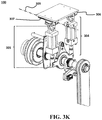
- FIG. 3K shows another perspective view of damping system 100 , consistent with one or more exemplary embodiments of the present disclosure.
- rotary damping mechanism 106 may further include a secondary linear shock absorber 305 which may be mounted slidably at a proximal end 352 of secondary linear shock absorber 305 onto a secondary guide rail 307 .
- secondary guide rail 307 may be attached fixedly to chassis 102 .
- secondary guide rail 307 may limit movements of secondary linear shock absorber 305 to a linear movement along a third axis 309 .
- third axis 309 may be an axis passing through secondary guide rail 307 and is parallel to first axis 144 .
- secondary linear shock absorber 305 may be substantially similar to linear shock absorber 304 in structure and functionality.
- secondary guide rail 307 may be substantially similar to guide rail 306 in structure and functionality.
- FIG. 3L shows rotary actuator 103 and main shaft 104 , consistent with one or more exemplary embodiments of the present disclosure.
- FIG. 3M shows another perspective view of damping system 100 , consistent with one or more exemplary embodiments of the present disclosure.
- rotary damping mechanism 106 may further include a non-rotating gear 350 .
- non-rotating gear 350 maybe mounted freely onto main shaft 104 and next to first externally-threaded gear 302 .
- an external diameter of non-rotating gear 350 may correspond to an external diameter of first externally-threaded gear 302 .
- non-rotating gear 350 may be configured to remain non-rotating during rotation of main shaft.
- non-rotating gear 350 may further configured to hold internally-threaded gear 312 when first externally-threaded gear 302 is decoupled from linear shock absorber 304 .
- Benefits from non-rotating gear 350 may include, but not limited, to a facility that may help internally-threaded gear 312 be coupled and decoupled easily from first externally-threaded gear 302 .
- non-rotating gear 350 may be mounted freely onto main shaft 104 by utilizing a needle roller bearing 352 .
- needle roller bearing 352 may be disposed between non-rotating gear 350 and main shaft 104 .
- needle roller bearing 352 may be attached fixedly to non-rotating gear 350 .
- needle roller bearing 352 may be mounted onto main shaft 104 .
- rotary damping mechanism 106 may further include a holding plate 360 .
- holding plate 360 may be mounted freely onto main shaft 104 .
- when an element is mounted freely onto a shaft it may refer to the fact that during the rotation of the shaft, the element may not rotate with the main shaft, and consequently, the element may remain non-rotating during rotation of the shaft.
- holding plate 360 may be configured to hold first actuator 318 .
- damping system 100 may further include a locking mechanism 108 .
- FIG. 4A shows a perspective view of locking mechanism 108 , consistent with one or more exemplary embodiments of the present disclosure.
- FIG. 4B shows a side view of locking mechanism 108 , consistent with one or more exemplary embodiments of the present disclosure.
- locking mechanism 108 may include a second externally-threaded gear 402 mounted fixedly onto main shaft 104 .
- second externally-threaded gear 402 may be mounted or otherwise attached to main shaft 104 in such a way that any movement of second externally-threaded gear 402 relative to main shaft 104 is minimized or prevented.
- second externally-threaded gear 402 may be mounted or otherwise attached to main shaft 104 via a screw mechanism and/or any other similar connecting mechanisms.
- second externally-threaded gear 402 and main shaft 104 may be manufactured seamlessly in order to constitute a unique or unitary/integral part.
- second externally-threaded gear 402 may include an externally threaded section 422 provided on an outermost surface of second externally-threaded gear 402 .
- second externally-threaded gear 402 may no longer be able to rotate around first axis 104 .
- engaging an element with a threaded section may refer to disposing the element between two consecutive gears of the threaded section.
- FIG. 4C shows second externally-threaded gear 402 mounted fixedly onto main shaft 104 , consistent with one or more exemplary embodiments of the present disclosure.
- locking mechanism 108 may further include a scissor-like mechanism 404 .
- FIG. 4D shows scissor-like mechanism 404 , consistent with one or more exemplary embodiments of the present disclosure.
- scissor-like mechanism 404 may include a base 442 which may be attached fixedly to chassis 102 .
- scissor-like mechanism 404 may further include a first rod 444 and a second rod 446 .
- First rod 444 and second rod 446 may be attached pivotally to base 442 .
- pivotal attachment may refer to an attachment that allow two attached elements to rotate around the attach point.
- first rod 444 may be configured to prevent, or otherwise minimize, rotational movement of second externally-threaded gear 402 around first axis 144 when a distal end 4442 of first rod 444 is engaged with second externally threaded section 422 of second externally-threaded gear 402 .
- distal end 4442 of first rod 444 is engaged with second externally threaded section 422 of second externally-threaded gear 402
- distal end 4442 is disposed between two consecutive gears of externally threaded section 422 and, consequently, second externally-threaded gear 402 may, no longer, be able to rotate around first axis 144 .
- second rod 446 may be configured to prevent, or otherwise minimize, rotational movement of second externally-threaded gear 402 around first axis 144 when a distal end 4462 of second rod 446 is engaged with second externally threaded section 422 of second externally-threaded gear 402 .
- distal end 4462 of first rod 444 is engaged with second externally threaded section 422 of second externally-threaded gear 402
- distal end 4442 is disposed between two consecutive gears of externally threaded section 422 and, consequently, second externally-threaded gear 402 may, no longer, be able to rotate around first axis 144 .
- scissor-like mechanism 404 may further include a second actuator 448 .
- second actuator 448 may be disposed between a proximal end 4444 of first rod 444 and a proximal end 4464 of second rod 446 .
- second actuator 448 may be attached pivotally at a first end 4482 of second actuator 448 to proximal end 444 of first rod 446 and attached pivotally at a second end 4484 of second actuator 448 to proximal end 4464 of second rod 444 .
- second actuator 448 may be configured to engage distal end 4442 of first rod 444 and distal end 4462 of second rod 446 with second externally threaded section 422 of second externally-threaded gear 402 by applying a pull force between proximal end 4444 of first rod 444 and proximal end 4464 of second rod 446 .
- FIG. 4E shows locking mechanism 108 in an exemplary scenario when distal end 4442 of first rod 444 and distal end 4462 of second rod 446 are engaged with second externally threaded section 422 of second externally-threaded gear 402 , consistent with one or more exemplary embodiments of the present disclosure.
- locking mechanism 108 may be configured to prevent rotary movements of main shaft 104 and tailing arm 202 around first axis 144 when distal end 4442 of the first rod 444 and distal end 4462 of second rod 446 are engaged with second externally threaded section 422 of second externally-threaded gear 402 .
- FIG. 4F shows another view of scissor-like mechanism 404 , consistent with one or more exemplary embodiments of the present disclosure.
- scissor-like mechanism 404 may further include a stopping member 449 which may be configured to prevent rotating of first rod 444 and second rod 446 around a pivot point 450 by an amount of more than a predetermined angle.
- stopping member 449 may be located in a place under second rod 446 as shown in FIGS. 4D, 4E, and 4F .
- the predetermined angle may be adjusted by altering a location of stopping member 449 along scissor-like mechanism 404 .
- higher location of stopping member 449 may lead to a smaller predetermined angle.
- damping system 100 may further include a controller.
- the controller may be connected to rotary actuator 103 , first actuator 318 , and second actuator 448 .
- the controller may be configured to control movements of rotary actuator 103 , first actuator 318 , and second actuator 448 .
Landscapes
- Engineering & Computer Science (AREA)
- General Engineering & Computer Science (AREA)
- Mechanical Engineering (AREA)
- Physics & Mathematics (AREA)
- Acoustics & Sound (AREA)
- Aviation & Aerospace Engineering (AREA)
- Transmission Devices (AREA)
- Fluid-Damping Devices (AREA)
- Vibration Prevention Devices (AREA)
Abstract
Description
Claims (16)
Priority Applications (1)
| Application Number | Priority Date | Filing Date | Title |
|---|---|---|---|
| US16/660,012 US11035430B2 (en) | 2018-10-22 | 2019-10-22 | Rotary damping |
Applications Claiming Priority (2)
| Application Number | Priority Date | Filing Date | Title |
|---|---|---|---|
| US201862748538P | 2018-10-22 | 2018-10-22 | |
| US16/660,012 US11035430B2 (en) | 2018-10-22 | 2019-10-22 | Rotary damping |
Publications (2)
| Publication Number | Publication Date |
|---|---|
| US20200049218A1 US20200049218A1 (en) | 2020-02-13 |
| US11035430B2 true US11035430B2 (en) | 2021-06-15 |
Family
ID=69406956
Family Applications (1)
| Application Number | Title | Priority Date | Filing Date |
|---|---|---|---|
| US16/660,012 Expired - Fee Related US11035430B2 (en) | 2018-10-22 | 2019-10-22 | Rotary damping |
Country Status (2)
| Country | Link |
|---|---|
| US (1) | US11035430B2 (en) |
| WO (1) | WO2020084493A1 (en) |
Families Citing this family (1)
| Publication number | Priority date | Publication date | Assignee | Title |
|---|---|---|---|---|
| CN114033832B (en) * | 2021-11-05 | 2023-03-28 | 兰州理工大学 | Two-dimensional integrated semi-active vibration control device based on impact vibration reduction |
Citations (8)
| Publication number | Priority date | Publication date | Assignee | Title |
|---|---|---|---|---|
| US4056158A (en) * | 1975-04-16 | 1977-11-01 | Minister Of Agriculture, Fisheries & Food, In Her Britanic Majesty's Government Of The U.K. Of Great Britain & N. Ireland | Rough terrain vehicles |
| US4600069A (en) * | 1982-09-28 | 1986-07-15 | Standard Manufacturing Company, Inc. | Trailing arm suspension |
| US6622829B2 (en) * | 2000-01-31 | 2003-09-23 | Delphi Technologies, Inc. | Rotary Damper |
| US7261176B2 (en) * | 2003-02-21 | 2007-08-28 | Lockheed Martin Corporation | Articulated vehicle suspension system shoulder joint |
| US7950973B2 (en) * | 2007-12-18 | 2011-05-31 | Hewitt Stanley C | Amphibious vehicle |
| US8672065B2 (en) * | 2003-02-21 | 2014-03-18 | Lockheed Martin Corporation | Vehicle having an articulated suspension and method of using same |
| US10036443B2 (en) * | 2009-03-19 | 2018-07-31 | Fox Factory, Inc. | Methods and apparatus for suspension adjustment |
| US10807430B2 (en) * | 2015-12-11 | 2020-10-20 | Hendrickson United Kingdom Ltd | Axle/suspension systems |
Family Cites Families (2)
| Publication number | Priority date | Publication date | Assignee | Title |
|---|---|---|---|---|
| DE102007014124B4 (en) * | 2007-03-23 | 2013-01-24 | Saf-Holland Gmbh | shock absorber |
| DE102012009168A1 (en) * | 2012-05-08 | 2013-11-14 | Audi Ag | Damping device with a rotary damper |
-
2019
- 2019-10-22 WO PCT/IB2019/059024 patent/WO2020084493A1/en not_active Ceased
- 2019-10-22 US US16/660,012 patent/US11035430B2/en not_active Expired - Fee Related
Patent Citations (8)
| Publication number | Priority date | Publication date | Assignee | Title |
|---|---|---|---|---|
| US4056158A (en) * | 1975-04-16 | 1977-11-01 | Minister Of Agriculture, Fisheries & Food, In Her Britanic Majesty's Government Of The U.K. Of Great Britain & N. Ireland | Rough terrain vehicles |
| US4600069A (en) * | 1982-09-28 | 1986-07-15 | Standard Manufacturing Company, Inc. | Trailing arm suspension |
| US6622829B2 (en) * | 2000-01-31 | 2003-09-23 | Delphi Technologies, Inc. | Rotary Damper |
| US7261176B2 (en) * | 2003-02-21 | 2007-08-28 | Lockheed Martin Corporation | Articulated vehicle suspension system shoulder joint |
| US8672065B2 (en) * | 2003-02-21 | 2014-03-18 | Lockheed Martin Corporation | Vehicle having an articulated suspension and method of using same |
| US7950973B2 (en) * | 2007-12-18 | 2011-05-31 | Hewitt Stanley C | Amphibious vehicle |
| US10036443B2 (en) * | 2009-03-19 | 2018-07-31 | Fox Factory, Inc. | Methods and apparatus for suspension adjustment |
| US10807430B2 (en) * | 2015-12-11 | 2020-10-20 | Hendrickson United Kingdom Ltd | Axle/suspension systems |
Also Published As
| Publication number | Publication date |
|---|---|
| US20200049218A1 (en) | 2020-02-13 |
| WO2020084493A1 (en) | 2020-04-30 |
Similar Documents
| Publication | Publication Date | Title |
|---|---|---|
| CN101896369B (en) | Spring strut device for motor vehicle wheel suspension structure | |
| CN107521547B (en) | Self-locking telescopic actuator for steering column assembly | |
| US11001116B2 (en) | Electromechanical chasis actuator | |
| CN1717340B (en) | Vehicle running mechanism | |
| US7135794B2 (en) | Spring support having a height-adjustable spring plate | |
| CN106103239B (en) | Steering device | |
| CN106183681A (en) | Omni-directional moving platform with damping device | |
| CN107757289B (en) | Suspension and vehicle | |
| JP7295109B2 (en) | Damper and spring unit for vehicle suspension with electromechanical adjusting device for adjusting the vertical position of the spring | |
| US20150251513A1 (en) | Rotary damper | |
| US11035430B2 (en) | Rotary damping | |
| US20200248788A1 (en) | Linear actuator | |
| CN114599898B (en) | Actuator or suspension | |
| CN116531188A (en) | Shock-absorbing stretcher platform for ambulance | |
| CN105835940A (en) | Steering column and automobile steering system | |
| KR20230046919A (en) | Steering column for automotive | |
| CN108860288B (en) | Steering column assembly | |
| CN209492586U (en) | Telescopic steering column and automobile comprising same | |
| CN109878567A (en) | A kind of steering tiller and the warehouse trucks including steering tiller | |
| JP2010025139A (en) | Suspension device for vehicle | |
| CN210793326U (en) | Connecting mechanism between shock absorber and steering knuckle, suspension system and vehicle | |
| CN109853411A (en) | The vehicle rate controlling equipment of the cyclic annular seamless transitions of speed-limit road section | |
| JP2010179728A (en) | Vehicle height adjusting device | |
| JP7582094B2 (en) | Steering gear | |
| JP2008202738A (en) | Vehicle suspension system |
Legal Events
| Date | Code | Title | Description |
|---|---|---|---|
| FEPP | Fee payment procedure |
Free format text: ENTITY STATUS SET TO UNDISCOUNTED (ORIGINAL EVENT CODE: BIG.); ENTITY STATUS OF PATENT OWNER: SMALL ENTITY |
|
| FEPP | Fee payment procedure |
Free format text: ENTITY STATUS SET TO SMALL (ORIGINAL EVENT CODE: SMAL); ENTITY STATUS OF PATENT OWNER: SMALL ENTITY |
|
| STPP | Information on status: patent application and granting procedure in general |
Free format text: APPLICATION DISPATCHED FROM PREEXAM, NOT YET DOCKETED |
|
| STPP | Information on status: patent application and granting procedure in general |
Free format text: NOTICE OF ALLOWANCE MAILED -- APPLICATION RECEIVED IN OFFICE OF PUBLICATIONS |
|
| STPP | Information on status: patent application and granting procedure in general |
Free format text: PUBLICATIONS -- ISSUE FEE PAYMENT RECEIVED |
|
| STPP | Information on status: patent application and granting procedure in general |
Free format text: PUBLICATIONS -- ISSUE FEE PAYMENT VERIFIED |
|
| STCF | Information on status: patent grant |
Free format text: PATENTED CASE |
|
| AS | Assignment |
Owner name: AMIRKABIR UNIVERSITY OF TECHNOLOGY, IRAN, ISLAMIC REPUBLIC OF Free format text: ASSIGNMENT OF ASSIGNORS INTEREST;ASSIGNORS:GHASSABZADEH SARYAZDI, MARYAM;DAGHAGH, MEHRDAD;SOLTANI VELASHJERD, MOHAMMAD;REEL/FRAME:056396/0058 Effective date: 20210523 Owner name: GHASSABZADEH SARYAZDI, MARYAM, IRAN, ISLAMIC REPUBLIC OF Free format text: ASSIGNMENT OF ASSIGNORS INTEREST;ASSIGNORS:GHASSABZADEH SARYAZDI, MARYAM;DAGHAGH, MEHRDAD;SOLTANI VELASHJERD, MOHAMMAD;REEL/FRAME:056396/0058 Effective date: 20210523 Owner name: DAGHAGH, MEHRDAD, IRAN, ISLAMIC REPUBLIC OF Free format text: ASSIGNMENT OF ASSIGNORS INTEREST;ASSIGNORS:GHASSABZADEH SARYAZDI, MARYAM;DAGHAGH, MEHRDAD;SOLTANI VELASHJERD, MOHAMMAD;REEL/FRAME:056396/0058 Effective date: 20210523 Owner name: SOLTANI VELASHJERD, MOHAMMAD, IRAN, ISLAMIC REPUBLIC OF Free format text: ASSIGNMENT OF ASSIGNORS INTEREST;ASSIGNORS:GHASSABZADEH SARYAZDI, MARYAM;DAGHAGH, MEHRDAD;SOLTANI VELASHJERD, MOHAMMAD;REEL/FRAME:056396/0058 Effective date: 20210523 |
|
| FEPP | Fee payment procedure |
Free format text: MAINTENANCE FEE REMINDER MAILED (ORIGINAL EVENT CODE: REM.); ENTITY STATUS OF PATENT OWNER: SMALL ENTITY |
|
| LAPS | Lapse for failure to pay maintenance fees |
Free format text: PATENT EXPIRED FOR FAILURE TO PAY MAINTENANCE FEES (ORIGINAL EVENT CODE: EXP.); ENTITY STATUS OF PATENT OWNER: SMALL ENTITY |
|
| STCH | Information on status: patent discontinuation |
Free format text: PATENT EXPIRED DUE TO NONPAYMENT OF MAINTENANCE FEES UNDER 37 CFR 1.362 |
|
| FP | Lapsed due to failure to pay maintenance fee |
Effective date: 20250615 |