US11035305B2 - 2-cycle engine with valve system and method for controlling the engine - Google Patents
2-cycle engine with valve system and method for controlling the engine Download PDFInfo
- Publication number
- US11035305B2 US11035305B2 US16/589,442 US201916589442A US11035305B2 US 11035305 B2 US11035305 B2 US 11035305B2 US 201916589442 A US201916589442 A US 201916589442A US 11035305 B2 US11035305 B2 US 11035305B2
- Authority
- US
- United States
- Prior art keywords
- air intake
- exhaust
- valve
- engine
- current
- Prior art date
- Legal status (The legal status is an assumption and is not a legal conclusion. Google has not performed a legal analysis and makes no representation as to the accuracy of the status listed.)
- Expired - Fee Related
Links
Images


Classifications
-
- F—MECHANICAL ENGINEERING; LIGHTING; HEATING; WEAPONS; BLASTING
- F02—COMBUSTION ENGINES; HOT-GAS OR COMBUSTION-PRODUCT ENGINE PLANTS
- F02D—CONTROLLING COMBUSTION ENGINES
- F02D13/00—Controlling the engine output power by varying inlet or exhaust valve operating characteristics, e.g. timing
- F02D13/02—Controlling the engine output power by varying inlet or exhaust valve operating characteristics, e.g. timing during engine operation
- F02D13/0203—Variable control of intake and exhaust valves
- F02D13/0215—Variable control of intake and exhaust valves changing the valve timing only
-
- F—MECHANICAL ENGINEERING; LIGHTING; HEATING; WEAPONS; BLASTING
- F02—COMBUSTION ENGINES; HOT-GAS OR COMBUSTION-PRODUCT ENGINE PLANTS
- F02D—CONTROLLING COMBUSTION ENGINES
- F02D41/00—Electrical control of supply of combustible mixture or its constituents
- F02D41/02—Circuit arrangements for generating control signals
- F02D41/14—Introducing closed-loop corrections
- F02D41/1438—Introducing closed-loop corrections using means for determining characteristics of the combustion gases; Sensors therefor
- F02D41/1444—Introducing closed-loop corrections using means for determining characteristics of the combustion gases; Sensors therefor characterised by the characteristics of the combustion gases
- F02D41/1448—Introducing closed-loop corrections using means for determining characteristics of the combustion gases; Sensors therefor characterised by the characteristics of the combustion gases the characteristics being an exhaust gas pressure
-
- B—PERFORMING OPERATIONS; TRANSPORTING
- B60—VEHICLES IN GENERAL
- B60K—ARRANGEMENT OR MOUNTING OF PROPULSION UNITS OR OF TRANSMISSIONS IN VEHICLES; ARRANGEMENT OR MOUNTING OF PLURAL DIVERSE PRIME-MOVERS IN VEHICLES; AUXILIARY DRIVES FOR VEHICLES; INSTRUMENTATION OR DASHBOARDS FOR VEHICLES; ARRANGEMENTS IN CONNECTION WITH COOLING, AIR INTAKE, GAS EXHAUST OR FUEL SUPPLY OF PROPULSION UNITS IN VEHICLES
- B60K6/00—Arrangement or mounting of plural diverse prime-movers for mutual or common propulsion, e.g. hybrid propulsion systems comprising electric motors and internal combustion engines
- B60K6/20—Arrangement or mounting of plural diverse prime-movers for mutual or common propulsion, e.g. hybrid propulsion systems comprising electric motors and internal combustion engines the prime-movers consisting of electric motors and internal combustion engines, e.g. HEVs
- B60K6/22—Arrangement or mounting of plural diverse prime-movers for mutual or common propulsion, e.g. hybrid propulsion systems comprising electric motors and internal combustion engines the prime-movers consisting of electric motors and internal combustion engines, e.g. HEVs characterised by apparatus, components or means specially adapted for HEVs
- B60K6/24—Arrangement or mounting of plural diverse prime-movers for mutual or common propulsion, e.g. hybrid propulsion systems comprising electric motors and internal combustion engines the prime-movers consisting of electric motors and internal combustion engines, e.g. HEVs characterised by apparatus, components or means specially adapted for HEVs characterised by the combustion engines
-
- B—PERFORMING OPERATIONS; TRANSPORTING
- B60—VEHICLES IN GENERAL
- B60K—ARRANGEMENT OR MOUNTING OF PROPULSION UNITS OR OF TRANSMISSIONS IN VEHICLES; ARRANGEMENT OR MOUNTING OF PLURAL DIVERSE PRIME-MOVERS IN VEHICLES; AUXILIARY DRIVES FOR VEHICLES; INSTRUMENTATION OR DASHBOARDS FOR VEHICLES; ARRANGEMENTS IN CONNECTION WITH COOLING, AIR INTAKE, GAS EXHAUST OR FUEL SUPPLY OF PROPULSION UNITS IN VEHICLES
- B60K6/00—Arrangement or mounting of plural diverse prime-movers for mutual or common propulsion, e.g. hybrid propulsion systems comprising electric motors and internal combustion engines
- B60K6/20—Arrangement or mounting of plural diverse prime-movers for mutual or common propulsion, e.g. hybrid propulsion systems comprising electric motors and internal combustion engines the prime-movers consisting of electric motors and internal combustion engines, e.g. HEVs
- B60K6/22—Arrangement or mounting of plural diverse prime-movers for mutual or common propulsion, e.g. hybrid propulsion systems comprising electric motors and internal combustion engines the prime-movers consisting of electric motors and internal combustion engines, e.g. HEVs characterised by apparatus, components or means specially adapted for HEVs
- B60K6/26—Arrangement or mounting of plural diverse prime-movers for mutual or common propulsion, e.g. hybrid propulsion systems comprising electric motors and internal combustion engines the prime-movers consisting of electric motors and internal combustion engines, e.g. HEVs characterised by apparatus, components or means specially adapted for HEVs characterised by the motors or the generators
-
- F—MECHANICAL ENGINEERING; LIGHTING; HEATING; WEAPONS; BLASTING
- F01—MACHINES OR ENGINES IN GENERAL; ENGINE PLANTS IN GENERAL; STEAM ENGINES
- F01L—CYCLICALLY OPERATING VALVES FOR MACHINES OR ENGINES
- F01L1/00—Valve-gear or valve arrangements, e.g. lift-valve gear
- F01L1/02—Valve drive
- F01L1/024—Belt drive
-
- F—MECHANICAL ENGINEERING; LIGHTING; HEATING; WEAPONS; BLASTING
- F01—MACHINES OR ENGINES IN GENERAL; ENGINE PLANTS IN GENERAL; STEAM ENGINES
- F01L—CYCLICALLY OPERATING VALVES FOR MACHINES OR ENGINES
- F01L1/00—Valve-gear or valve arrangements, e.g. lift-valve gear
- F01L1/34—Valve-gear or valve arrangements, e.g. lift-valve gear characterised by the provision of means for changing the timing of the valves without changing the duration of opening and without affecting the magnitude of the valve lift
- F01L1/344—Valve-gear or valve arrangements, e.g. lift-valve gear characterised by the provision of means for changing the timing of the valves without changing the duration of opening and without affecting the magnitude of the valve lift changing the angular relationship between crankshaft and camshaft, e.g. using helicoidal gear
-
- F—MECHANICAL ENGINEERING; LIGHTING; HEATING; WEAPONS; BLASTING
- F01—MACHINES OR ENGINES IN GENERAL; ENGINE PLANTS IN GENERAL; STEAM ENGINES
- F01L—CYCLICALLY OPERATING VALVES FOR MACHINES OR ENGINES
- F01L1/00—Valve-gear or valve arrangements, e.g. lift-valve gear
- F01L1/36—Valve-gear or valve arrangements, e.g. lift-valve gear peculiar to machines or engines of specific type other than four-stroke cycle
- F01L1/40—Valve-gear or valve arrangements, e.g. lift-valve gear peculiar to machines or engines of specific type other than four-stroke cycle for engines with scavenging charge near top dead centre position, e.g. by overlapping inlet and exhaust time
-
- F—MECHANICAL ENGINEERING; LIGHTING; HEATING; WEAPONS; BLASTING
- F02—COMBUSTION ENGINES; HOT-GAS OR COMBUSTION-PRODUCT ENGINE PLANTS
- F02B—INTERNAL-COMBUSTION PISTON ENGINES; COMBUSTION ENGINES IN GENERAL
- F02B25/00—Engines characterised by using fresh charge for scavenging cylinders
- F02B25/14—Engines characterised by using fresh charge for scavenging cylinders using reverse-flow scavenging, e.g. with both outlet and inlet ports arranged near bottom of piston stroke
- F02B25/145—Engines characterised by using fresh charge for scavenging cylinders using reverse-flow scavenging, e.g. with both outlet and inlet ports arranged near bottom of piston stroke with intake and exhaust valves exclusively in the cylinder head
-
- F—MECHANICAL ENGINEERING; LIGHTING; HEATING; WEAPONS; BLASTING
- F02—COMBUSTION ENGINES; HOT-GAS OR COMBUSTION-PRODUCT ENGINE PLANTS
- F02B—INTERNAL-COMBUSTION PISTON ENGINES; COMBUSTION ENGINES IN GENERAL
- F02B37/00—Engines characterised by provision of pumps driven at least for part of the time by exhaust
- F02B37/12—Control of the pumps
-
- F—MECHANICAL ENGINEERING; LIGHTING; HEATING; WEAPONS; BLASTING
- F02—COMBUSTION ENGINES; HOT-GAS OR COMBUSTION-PRODUCT ENGINE PLANTS
- F02B—INTERNAL-COMBUSTION PISTON ENGINES; COMBUSTION ENGINES IN GENERAL
- F02B75/00—Other engines
- F02B75/02—Engines characterised by their cycles, e.g. six-stroke
-
- F—MECHANICAL ENGINEERING; LIGHTING; HEATING; WEAPONS; BLASTING
- F02—COMBUSTION ENGINES; HOT-GAS OR COMBUSTION-PRODUCT ENGINE PLANTS
- F02D—CONTROLLING COMBUSTION ENGINES
- F02D13/00—Controlling the engine output power by varying inlet or exhaust valve operating characteristics, e.g. timing
- F02D13/02—Controlling the engine output power by varying inlet or exhaust valve operating characteristics, e.g. timing during engine operation
- F02D13/0223—Variable control of the intake valves only
- F02D13/0234—Variable control of the intake valves only changing the valve timing only
-
- F—MECHANICAL ENGINEERING; LIGHTING; HEATING; WEAPONS; BLASTING
- F02—COMBUSTION ENGINES; HOT-GAS OR COMBUSTION-PRODUCT ENGINE PLANTS
- F02D—CONTROLLING COMBUSTION ENGINES
- F02D23/00—Controlling engines characterised by their being supercharged
-
- F—MECHANICAL ENGINEERING; LIGHTING; HEATING; WEAPONS; BLASTING
- F02—COMBUSTION ENGINES; HOT-GAS OR COMBUSTION-PRODUCT ENGINE PLANTS
- F02D—CONTROLLING COMBUSTION ENGINES
- F02D41/00—Electrical control of supply of combustible mixture or its constituents
- F02D41/0002—Controlling intake air
- F02D41/0007—Controlling intake air for control of turbo-charged or super-charged engines
-
- F—MECHANICAL ENGINEERING; LIGHTING; HEATING; WEAPONS; BLASTING
- F02—COMBUSTION ENGINES; HOT-GAS OR COMBUSTION-PRODUCT ENGINE PLANTS
- F02M—SUPPLYING COMBUSTION ENGINES IN GENERAL WITH COMBUSTIBLE MIXTURES OR CONSTITUENTS THEREOF
- F02M35/00—Combustion-air cleaners, air intakes, intake silencers, or induction systems specially adapted for, or arranged on, internal-combustion engines
- F02M35/10—Air intakes; Induction systems
- F02M35/104—Intake manifolds
-
- B—PERFORMING OPERATIONS; TRANSPORTING
- B60—VEHICLES IN GENERAL
- B60Y—INDEXING SCHEME RELATING TO ASPECTS CROSS-CUTTING VEHICLE TECHNOLOGY
- B60Y2200/00—Type of vehicle
- B60Y2200/90—Vehicles comprising electric prime movers
- B60Y2200/92—Hybrid vehicles
-
- F—MECHANICAL ENGINEERING; LIGHTING; HEATING; WEAPONS; BLASTING
- F01—MACHINES OR ENGINES IN GENERAL; ENGINE PLANTS IN GENERAL; STEAM ENGINES
- F01L—CYCLICALLY OPERATING VALVES FOR MACHINES OR ENGINES
- F01L1/00—Valve-gear or valve arrangements, e.g. lift-valve gear
- F01L1/02—Valve drive
- F01L1/04—Valve drive by means of cams, camshafts, cam discs, eccentrics or the like
- F01L1/047—Camshafts
- F01L1/053—Camshafts overhead type
- F01L1/0532—Camshafts overhead type the cams being directly in contact with the driven valve
-
- F—MECHANICAL ENGINEERING; LIGHTING; HEATING; WEAPONS; BLASTING
- F01—MACHINES OR ENGINES IN GENERAL; ENGINE PLANTS IN GENERAL; STEAM ENGINES
- F01L—CYCLICALLY OPERATING VALVES FOR MACHINES OR ENGINES
- F01L1/00—Valve-gear or valve arrangements, e.g. lift-valve gear
- F01L1/12—Transmitting gear between valve drive and valve
- F01L1/18—Rocking arms or levers
- F01L1/185—Overhead end-pivot rocking arms
-
- F—MECHANICAL ENGINEERING; LIGHTING; HEATING; WEAPONS; BLASTING
- F01—MACHINES OR ENGINES IN GENERAL; ENGINE PLANTS IN GENERAL; STEAM ENGINES
- F01L—CYCLICALLY OPERATING VALVES FOR MACHINES OR ENGINES
- F01L1/00—Valve-gear or valve arrangements, e.g. lift-valve gear
- F01L1/02—Valve drive
- F01L1/04—Valve drive by means of cams, camshafts, cam discs, eccentrics or the like
- F01L1/047—Camshafts
- F01L1/053—Camshafts overhead type
- F01L2001/0537—Double overhead camshafts [DOHC]
-
- F—MECHANICAL ENGINEERING; LIGHTING; HEATING; WEAPONS; BLASTING
- F01—MACHINES OR ENGINES IN GENERAL; ENGINE PLANTS IN GENERAL; STEAM ENGINES
- F01L—CYCLICALLY OPERATING VALVES FOR MACHINES OR ENGINES
- F01L2305/00—Valve arrangements comprising rollers
-
- F—MECHANICAL ENGINEERING; LIGHTING; HEATING; WEAPONS; BLASTING
- F02—COMBUSTION ENGINES; HOT-GAS OR COMBUSTION-PRODUCT ENGINE PLANTS
- F02B—INTERNAL-COMBUSTION PISTON ENGINES; COMBUSTION ENGINES IN GENERAL
- F02B37/00—Engines characterised by provision of pumps driven at least for part of the time by exhaust
- F02B37/12—Control of the pumps
- F02B2037/122—Control of rotational speed of the pump
-
- F—MECHANICAL ENGINEERING; LIGHTING; HEATING; WEAPONS; BLASTING
- F02—COMBUSTION ENGINES; HOT-GAS OR COMBUSTION-PRODUCT ENGINE PLANTS
- F02B—INTERNAL-COMBUSTION PISTON ENGINES; COMBUSTION ENGINES IN GENERAL
- F02B75/00—Other engines
- F02B75/02—Engines characterised by their cycles, e.g. six-stroke
- F02B2075/022—Engines characterised by their cycles, e.g. six-stroke having less than six strokes per cycle
- F02B2075/025—Engines characterised by their cycles, e.g. six-stroke having less than six strokes per cycle two
-
- F—MECHANICAL ENGINEERING; LIGHTING; HEATING; WEAPONS; BLASTING
- F02—COMBUSTION ENGINES; HOT-GAS OR COMBUSTION-PRODUCT ENGINE PLANTS
- F02D—CONTROLLING COMBUSTION ENGINES
- F02D41/00—Electrical control of supply of combustible mixture or its constituents
- F02D41/0002—Controlling intake air
- F02D2041/001—Controlling intake air for engines with variable valve actuation
-
- F—MECHANICAL ENGINEERING; LIGHTING; HEATING; WEAPONS; BLASTING
- F02—COMBUSTION ENGINES; HOT-GAS OR COMBUSTION-PRODUCT ENGINE PLANTS
- F02D—CONTROLLING COMBUSTION ENGINES
- F02D2200/00—Input parameters for engine control
- F02D2200/02—Input parameters for engine control the parameters being related to the engine
- F02D2200/04—Engine intake system parameters
- F02D2200/0406—Intake manifold pressure
-
- F—MECHANICAL ENGINEERING; LIGHTING; HEATING; WEAPONS; BLASTING
- F02—COMBUSTION ENGINES; HOT-GAS OR COMBUSTION-PRODUCT ENGINE PLANTS
- F02D—CONTROLLING COMBUSTION ENGINES
- F02D2200/00—Input parameters for engine control
- F02D2200/02—Input parameters for engine control the parameters being related to the engine
- F02D2200/10—Parameters related to the engine output, e.g. engine torque or engine speed
-
- F—MECHANICAL ENGINEERING; LIGHTING; HEATING; WEAPONS; BLASTING
- F02—COMBUSTION ENGINES; HOT-GAS OR COMBUSTION-PRODUCT ENGINE PLANTS
- F02D—CONTROLLING COMBUSTION ENGINES
- F02D2400/00—Control systems adapted for specific engine types; Special features of engine control systems not otherwise provided for; Power supply, connectors or cabling for engine control systems
- F02D2400/04—Two-stroke combustion engines with electronic control
-
- F—MECHANICAL ENGINEERING; LIGHTING; HEATING; WEAPONS; BLASTING
- F02—COMBUSTION ENGINES; HOT-GAS OR COMBUSTION-PRODUCT ENGINE PLANTS
- F02D—CONTROLLING COMBUSTION ENGINES
- F02D35/00—Controlling engines, dependent on conditions exterior or interior to engines, not otherwise provided for
- F02D35/02—Controlling engines, dependent on conditions exterior or interior to engines, not otherwise provided for on interior conditions
- F02D35/027—Controlling engines, dependent on conditions exterior or interior to engines, not otherwise provided for on interior conditions using knock sensors
-
- F—MECHANICAL ENGINEERING; LIGHTING; HEATING; WEAPONS; BLASTING
- F02—COMBUSTION ENGINES; HOT-GAS OR COMBUSTION-PRODUCT ENGINE PLANTS
- F02D—CONTROLLING COMBUSTION ENGINES
- F02D39/00—Other non-electrical control
- F02D39/04—Other non-electrical control for engines with other cycles than four-stroke, e.g. two-stroke
-
- Y—GENERAL TAGGING OF NEW TECHNOLOGICAL DEVELOPMENTS; GENERAL TAGGING OF CROSS-SECTIONAL TECHNOLOGIES SPANNING OVER SEVERAL SECTIONS OF THE IPC; TECHNICAL SUBJECTS COVERED BY FORMER USPC CROSS-REFERENCE ART COLLECTIONS [XRACs] AND DIGESTS
- Y02—TECHNOLOGIES OR APPLICATIONS FOR MITIGATION OR ADAPTATION AGAINST CLIMATE CHANGE
- Y02T—CLIMATE CHANGE MITIGATION TECHNOLOGIES RELATED TO TRANSPORTATION
- Y02T10/00—Road transport of goods or passengers
- Y02T10/10—Internal combustion engine [ICE] based vehicles
- Y02T10/12—Improving ICE efficiencies
Definitions
- the present disclosure relates generally to a 2-cycle engine with a valve system and a method for controlling the engine.
- a 4-cycle engine is an internal combustion engine that generates power by performing a one cycle of air intake-compression-expansion-exhaust during two up-and-down movements of a piston.
- the 4-cycle engine has advantages as follows: combustion is stable due to each cycle of the engine divided completely from each other, thermal load of any one each part is small due to cooling effect in an air intake cycle, and volume efficiency is high due to a sufficient period of the air intake cycle.
- the present disclosure relates to a 2-cycle engine with a valve system configured to generate power during every one crankshaft rotation.
- a 2-cycle engine with a valve system includes a camshaft rotated in conjunction with a crankshaft, a valve system configured that an air intake valve and an exhaust valve are opened or closed depending on a camshaft rotation, a turbocharger compressing air and supplying the compressed air into a cylinder, and a controller controlling operation of the turbocharger using a difference between an intake pressure and an exhaust pressure so that a current air intake reaches a target air intake.
- the air intake valve and the exhaust valve may be opened and closed once, respectively, during one crankshaft rotation.
- crankshaft and the camshaft may be rotated at a rotation ratio of 1 to 1 (1:1).
- the gear teeth of a crank sprocket mounted to the crankshaft and gear teeth of a cam sprocket mounted to the camshaft may be formed in sizes and shapes corresponding to each other.
- crankshaft and the camshaft may be rotated at a rotation ratio of 2 to 1 (2:1), and a cam provided on the camshaft may be provided with two cam lobes symmetrically disposed.
- the controller includes a calculation unit that calculates engine demand torque based on factors reflecting vehicle traveling conditions, calculates the target air intake desired for generating the engine demand torque, and calculates a target air intake/exhaust pressure difference value corresponding to the target air intake, an input unit receiving a current intake pressure of an air intake manifold and a current exhaust pressure of an exhaust manifold, an input unit receiving a current intake pressure of an air intake manifold and a current exhaust pressure of an exhaust manifold, a comparison determination unit comparing a current air intake/exhaust pressure difference value that is a difference value between the current intake pressure and the current exhaust pressure with the target air intake/exhaust pressure difference value, and an output unit controlling a rotation speed of the turbocharger to increase the rotation speed when the target air intake/exhaust pressure difference value is higher than the current air intake/exhaust pressure difference value and controlling the rotation speed of the turbocharger to decrease the rotation speed when the target air intake/exhaust pressure difference value is equal to or less than
- the input unit may receive the intake pressure at an air intake valve closing time as the current intake pressure, and receive the exhaust pressure at an exhaust valve closing time as the current exhaust pressure.
- valve timings of the air intake valve and the exhaust valve may be determined so that a cycle of air intake-compression-expansion-exhaust may be performed during a first cycle in which a piston is moved from a bottom dead center to a top dead center depending on the crankshaft rotation and a second cycle in which the piston is moved from the top dead center to the bottom dead center.
- the controller may control the exhaust valve to be opened during a process in which the piston is moved downward from the top dead center to the bottom dead center and to be closed at a timing at which the exhaust pressure is equal to or less than a reference value when the piston is near the bottom dead center.
- the controller may control the air intake valve to be opened, and to be closed after the piston passes the bottom dead center.
- the 2-cycle engine may further include a variable valve device controlling the valve timings of the air intake valve and the exhaust valve.
- the controller may determine whether the engine knocks, and control operation of the variable valve device so that the variable valve device may control a closing timing of the air intake valve.
- the 2-cycle engine may further include a motorization device including a motor, a generator, and an inverter in order to generate an electrical driving force along with a driving force of the engine.
- a motorization device including a motor, a generator, and an inverter in order to generate an electrical driving force along with a driving force of the engine.
- the air intake valve and the exhaust valve may be disposed at an upper portion of the cylinder and may be controlled by a cam.
- a method for controlling the 2-cycle engine with the valve system of the present disclosure may be configured such that the controller controls operation of the turbocharger using difference between the intake pressure and the exhaust pressure so that the current air intake reaches the target air intake.
- the method may include the steps of calculating engine demand torque based on factors reflecting a vehicle traveling state, calculating target air intake desired for generating the engine demand torque when current engine torque is less than the engine demand torque, calculating the target air intake/exhaust pressure difference value corresponding to the target air intake, calculating the current air intake/exhaust pressure difference value by receiving the current intake pressure of the air intake manifold and the current exhaust pressure of the exhaust manifold, controlling the rotation speed of the turbocharger to increase the rotation speed when the target air intake/exhaust pressure difference value is higher than the current air intake/exhaust pressure difference value, and controlling the rotation speed of the turbocharger to decrease the rotation speed when the target air intake/exhaust pressure difference value is equal to or less than the current air intake/exhaust pressure difference value.
- the 2-cycle engine of the present disclosure performs one explosion cycle during every one crankshaft rotation, so that air displacement of the engine is reduced as compared with the 4-cycle engine of the same output, and the size and the weight of the engine can be reduced.
- friction, exhaust, and cooling losses of the 2-cycle engine are reduced as the number of cycles in the 2-cycle engine is reduced in comparison with the number of cycles in the 4-cycle engine, so that fuel efficiency is improved.
- the conventional 4-cycle engine is used as it is to realize the 2-cycle engine, there is no need to separately have a product line for the 2-cycle engine, and product cost is reduced.
- the 2-cycle engine is applied to a hybrid vehicle, since volumes of the motorization device (the motor, the generator, and the inverter) can be increased as much as a volume of the engine is reduced, the efficiency of the hybrid vehicle can be increased.
- the air intake flowing into a cylinder is controlled to provide stable combustion performance depending on engine load required in the engine.
- FIG. 1 is a view showing an example of a 2-cycle engine according to a form of the present disclosure
- FIG. 2 is a view showing a structure of the 2-cycle engine according to a form of the present disclosure to which a turbocharger is mounted and showing a part at which an intake pressure and an exhaust pressure are measured;
- FIG. 3 is a graph showing an example of a valve timing of the 2-cycle engine according to a form of the present disclosure
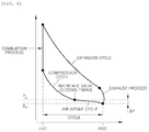
- FIG. 4 is a P-V diagram of the 2-cycle engine according to a form of the present disclosure.
- FIG. 5 is a block diagram showing a system of a controller which controls the turbocharger depending on an engine operation condition according to a form of the present disclosure
- FIG. 6 is a flowchart showing a control process in which the turbocharger is controlled depending on the 2-cycle engine operation condition according to a form of the present disclosure
- FIG. 7 is a graph showing a control status of the turbocharger in the 2-cycle engine according to a form of the present disclosure and showing pressures of a valve lift and a combustor depending on valve timings;
- FIG. 8 is a block diagram showing a hybrid system to which the 2-cycle engine according to a form of the present disclosure is applicable.
- an engine which is applicable to the present disclosure has a structure as follows.
- the engine system is configured such that a crankshaft 1 is mounted to a crank sprocket 3 , a camshaft 5 is mounted to a cam sprocket 7 , and a timing belt ora chain is put on the crank sprocket 3 and the cam sprocket 7 in order to allow the camshaft 5 to be rotated in conjunction with a rotation of the crankshaft 1 .
- the camshaft 5 is provided with a cam 9 , and the cam 9 is configured to apply an actuating force to a valve system including an air intake valve 13 , an exhaust valve 15 , and a valve spring depending on the cam rotation, so that the valves can be opened and closed. That is, since the cam profile form determines valve timing, a lift amount, and valve duration, a cycle from air intake to exhaust can be performed.
- the camshaft 5 is preferably a pair of camshafts arranged parallel to one another, as depicted, however a single camshaft 5 could be used with appropriately formed sprockets 7 and cams 9 to operate both the intake valves 13 and the exhaust valves 15 .
- a turbocharger 31 is mounted in the engine to supply compressed air into a cylinder, and the turbocharger 31 may be a supercharger.
- the turbocharger 31 when a turbine is rapidly rotated due to discharging of exhaust gas and thus a compressor is rotated together by an actuating force of the turbine, the turbocharger 31 compresses air inflowing through an air filter.
- the compressed air is cooled by passing through an intercooler, and the cooled air is supplied to a cylinder through an air intake manifold.
- MTV manifold throttle valve
- EGR exhaust gas recirculation
- a water injection is mounted in the air intake port to inject water, thereby reducing temperature of the engine and increasing air density, so that engine knocking can be suppressed in a knocking area.
- the present disclosure is characterized in that a 2-cycle engine may be realized while an existing 4-cycle engine is used as it is.
- the 2-cycle engine of the present disclosure is configured such that the air intake valve 13 and the exhaust valve 15 are opened and closed once, respectively, during one cycle of the crankshaft 1 .
- the present disclosure proposes that the crankshaft 1 and the camshaft 5 are rotated at a rotation ratio of 1 to 1 (1:1).
- the camshaft 5 is rotated once thereby performing a cycle from air intake to exhaust when the crankshaft 1 is rotated twice.
- the camshaft 5 is rotated once thereby performing the cycle from air intake to exhaust when the crankshaft 1 is rotated once.
- crankshaft 1 and the camshaft 5 are rotated at the rotation ratio of 1:1, gear teeth of the crank sprocket 3 mounted to the crankshaft 1 and gear teeth of the cam sprocket 7 mounted to the camshaft 5 are formed in sizes and shapes corresponding to each other, as shown in FIG. 1 .
- crank sprocket 3 and the cam sprocket 7 are formed in the same, thereby providing the rotation ratio of the crankshaft 1 and the camshaft 5 to 1:1.
- a size of the crank sprocket 3 (which is smaller than the cam sprocket in the 4-cycle engine) is increased to have the same size as the cam sprocket 7 in the 2-cycle engine, or a size of the cam sprocket 7 (which is bigger than the crank sprocket in the 4-cycle engine) is reduced to have the same size as the crank sprocket 3 in the 2-cycle engine.
- a height of an engine head can be reduced, which is preferable.
- the air intake valve 13 and the exhaust valve 15 are respectively opened and closed once during the crankshaft 1 is rotated once, the crankshaft 1 and the camshaft 5 may be rotated at a rotation ratio of 2 to 1 (2:1), and the cam provided on the camshaft 5 may be provided with two cam lobes which are symmetrically disposed.
- the 2-cycle engine of the present disclosure may include a controller (CLR) for controlling operation of the turbocharger 31 using a difference between an air intake pressure (Pin) and an exhaust pressure (Pex) so that a current air intake reaches a target air intake.
- the controller (CLR) includes a calculation unit 23 , an input unit 25 , a comparison determination unit 27 , and an output unit 29 .
- the controller is realized by an algorithm configured to control operations of various components of a vehicle or a non-volatile memory configured to store data regarding software instructions for running the algorithm (not shown) and a processor configured to perform operations described below using the data stored in the memory (not shown).
- the memory or the processor may be realized with a separate chip. Alternately, the memory and the processor may be realized together with an integral single chip.
- the processor may be configured as at least one processor.
- the calculation unit 23 calculates engine demand torque based on factors reflecting vehicle traveling conditions, calculates a target air intake desired for generating the engine demand torque when current engine torque is less than the engine demand torque, and calculates a target air intake/exhaust pressure difference value ( ⁇ P_target) corresponding to the target air intake.
- a value obtained by reducing air density at Pex from air density at Pin may be calculated as the difference between the air intake pressure (Pin) and the exhaust pressure (Pex), when a target air intake is calculated, a target air intake/exhaust pressure difference value ( ⁇ P_target) corresponding thereto may be calculated.
- the input unit 25 receives a current air intake pressure (Pin) by an air intake pressure sensor 19 provided in the air intake manifold, and receives a current exhaust pressure (Pex) by an exhaust pressure sensor 21 provided in the exhaust manifold.
- Pin current air intake pressure
- PVex current exhaust pressure
- the input unit 25 receives an air intake pressure (Pin) at an air intake valve closing timing as the current air intake pressure (Pin), and an exhaust pressure (Pex) at an exhaust valve closing timing as the current exhaust pressure (Pex).
- Pin air intake pressure
- Pex exhaust pressure
- the comparison determination unit 27 compares a current air intake/exhaust pressure difference value ( ⁇ P: Pin-Pex) and the target air intake/exhaust pressure difference value ( ⁇ P_target), wherein the current air intake/exhaust pressure difference value ( ⁇ P: Pin-Pex) is a difference value between a current air intake pressure (Pin) and a current exhaust pressure (Pex).
- the output unit 29 compares the target air intake/exhaust pressure difference value ( ⁇ P_target) and the current air intake/exhaust pressure difference value ( ⁇ P). With the comparison result, when the target air intake/exhaust pressure difference value ( ⁇ P_target) is higher than the current air intake/exhaust pressure difference value ( ⁇ P), the output unit 29 transmits a signal to control rotation speed of the turbocharger 31 to increase the rotation speed. Whereas, when the target air intake/exhaust pressure difference value ( ⁇ P_target) is equal to or less than the current air intake/exhaust pressure difference value ( ⁇ P), the output unit 29 transmits a signal to control the rotation speed of the turbocharger 31 to reduce the rotation speed. In addition, it is possible to control the rotation speed of the turbocharger 31 through a pressure control valve provided in the turbocharger 31 .
- a current air intake/exhaust pressure difference value is a ⁇ P 1 .
- the controller controls the turbocharger 31 to increase the rotation speed of the turbocharger 31 , thereby increasing an air intake pressure.
- a current air intake/exhaust pressure difference value is a ⁇ P 2 .
- the rotation speed of the turbocharger 31 is controlled to be increased.
- the controller controls the rotation speed of the turbocharger 31 to be reduced, so an air intake pressure is lowered.
- ⁇ P current air intake/exhaust pressure difference value
- ⁇ P_target target air intake/exhaust pressure difference value
- the controller controls the rotation speed of the turbocharger 31 to be reduced.
- valve timings of the air intake valve 13 and the exhaust valve 15 may be determined so that a cycle of air intake-compression-expansion-exhaust is performed during a first cycle in which a piston 17 (see FIG. 2 ) is moved from a bottom dead center (BDC) to a top dead center (TDC) depending on the crankshaft rotation and during a second cycle in which the piston 17 is moved from the TDC to BDC.
- the valve timings may be determined by the profile form of the cam 9 , and in the present disclosure, may be determined through a variable valve device 11 or the controller (CLR), as shown in FIG. 1 .
- the variable valve device 11 controls the valve timings of the air intake valve 13 and the exhaust valve 15 , and the controller (CLR) controls the variable valve device 11 by receiving the engine operation condition.
- the variable valve device 11 may be a continuously variable valve timing (CVVT), a variable valve duration (VVD), a continuously variable valve duration (CVVD), or a variable valve lift (VVL), and continuously variable valve lift (CVVL).
- CVVT continuously variable valve timing
- VVD variable valve duration
- CVVD continuously variable valve duration
- VVL variable valve lift
- CVVL continuously variable valve lift
- the controller may control operation of the variable valve device 11 so that the exhaust valve 15 is opened when the piston 17 is moved from the TDC to the BDC, and is closed at a timing at which the exhaust pressure is equal to or less than a reference value near the BDC, as shown in FIGS. 3 and 4 .
- controller may control to open the air intake valve 13 when the piston is near the BDC, and to close the air intake valve 13 after the piston passes the BDC.
- the controller (CLR) may control to open the exhaust valve 15 in a process in which the piston 17 is moved from the TDC to the BDC after an expansion cycle.
- the controller (CLR) may control to close the exhaust valve 15 after the piston passes the BDC at which the exhaust pressure is sufficiently reduced.
- controller (CLR) may control to open the air intake valve 13 before the piston passes the BDC so that the air intake valve 13 and the exhaust valve 15 overlaps together, and the controller (CLR) may control to close the air intake valve 13 at a suitable timing after the piston passes the BDC.
- the expansion cycle may be performed after the piston passes the TDC.
- the controller may receive a signal from a knocking sensor, determine whether or not the engine knocks by the signal from the knocking sensor, and control the variable valve device 11 so that the variable valve device 11 controls a closing timing of the air intake valve.
- the 2-cycle engine of the present disclosure includes a motorization device which includes a motor, a generator, and an inverter in order to generate an electrical driving force along with a driving force of the engine.
- the air intake valve and the exhaust valve are disposed at an upper portion of the cylinder and are controlled by a cam.
- the 2-cycle engine of the present disclosure may be applied to a hybrid system as shown in FIG. 8 , wherein a motor is connected to the engine by a media of an engine clutch so as to be power switchable, the engine is provided with a hybrid starter generator (HSG) which is capable of starting or generating through a belt pulley, the motor and the HSG are connected to the inverter and a current may be converted.
- HSG hybrid starter generator
- the method may be configured such that the controller (CLR) controls operation of the turbocharger 31 using difference between an air intake air pressure (Pin) and an exhaust pressure (Pex), so that a current air intake reaches the target air intake.
- the controller controls operation of the turbocharger 31 using difference between an air intake air pressure (Pin) and an exhaust pressure (Pex), so that a current air intake reaches the target air intake.
- the method may be realized through a process of FIG. 6 , the engine demand torque is calculated on the basis of factors reflecting vehicle traveling conditions (S 10 ).
- the factors reflecting vehicle traveling conditions may be a pressed degree of accelerator and a fuel injection amount.
- the target air intake/exhaust pressure difference value ( ⁇ P_target) corresponding to the target air intake is calculated (S 40 ).
- a current air intake/exhaust difference value ( ⁇ P) is calculated by receiving a current air intake pressure of the air intake manifold and a current exhaust pressure of the exhaust manifold from the air intake pressure sensor 19 and the exhaust pressure sensor 21 (S 50 ).
- the controller controls to increase rotation speed of the turbocharger 31 (S 70 ).
- the controller controls rotation speed of the turbocharger 31 to be reduced (S 80 ).
- the 2-cycle engine of the present disclosure is configured such that one expansion cycle is performed during every one crankshaft rotation, air displacement of the engine is reduced in comparison with the same output 4-cycle engine, thereby reducing a size and weight of the engine.
- the number of cycle is reduced, friction and exhaust, and cooling loss are also reduced, thereby improving fuel efficiency.
Landscapes
- Engineering & Computer Science (AREA)
- Mechanical Engineering (AREA)
- General Engineering & Computer Science (AREA)
- Chemical & Material Sciences (AREA)
- Combustion & Propulsion (AREA)
- Transportation (AREA)
- Output Control And Ontrol Of Special Type Engine (AREA)
- Supercharger (AREA)
Abstract
Description
Air intake=(air density @ Pin−air density @ Pex)*volume of cylinder (Vcyl), where Pin=air intake pressure (closing timing of air intake valve), and Pex=exhaust pressure (closing timing of exhaust valve).
Claims (9)
Applications Claiming Priority (2)
| Application Number | Priority Date | Filing Date | Title |
|---|---|---|---|
| KR10-2019-0042704 | 2019-04-11 | ||
| KR1020190042704A KR20200120807A (en) | 2019-04-11 | 2019-04-11 | 2 cycle engine with valve system and method for controled the engine |
Publications (2)
| Publication Number | Publication Date |
|---|---|
| US20200325837A1 US20200325837A1 (en) | 2020-10-15 |
| US11035305B2 true US11035305B2 (en) | 2021-06-15 |
Family
ID=72613075
Family Applications (1)
| Application Number | Title | Priority Date | Filing Date |
|---|---|---|---|
| US16/589,442 Expired - Fee Related US11035305B2 (en) | 2019-04-11 | 2019-10-01 | 2-cycle engine with valve system and method for controlling the engine |
Country Status (4)
| Country | Link |
|---|---|
| US (1) | US11035305B2 (en) |
| KR (1) | KR20200120807A (en) |
| CN (1) | CN111810290A (en) |
| DE (1) | DE102019216159A1 (en) |
Cited By (1)
| Publication number | Priority date | Publication date | Assignee | Title |
|---|---|---|---|---|
| WO2005114380A2 (en) | 2004-02-15 | 2005-12-01 | Xbiblio B.V. | Processing techniques for text capture from a rendered document |
Families Citing this family (2)
| Publication number | Priority date | Publication date | Assignee | Title |
|---|---|---|---|---|
| KR20220085546A (en) * | 2020-12-15 | 2022-06-22 | 현대자동차주식회사 | System and method for controlling engine starting of hybrid electric vehicle |
| CN115711172B (en) * | 2022-11-30 | 2024-06-04 | 东风汽车股份有限公司 | Pressure control method of supercharger |
Citations (7)
| Publication number | Priority date | Publication date | Assignee | Title |
|---|---|---|---|---|
| US5158044A (en) * | 1990-09-10 | 1992-10-27 | Isuzu Ceramics Research Institute Co., Ltd. | Engine selectively operable in two- and four-cycle modes |
| US5939794A (en) * | 1995-07-25 | 1999-08-17 | Nippon Soken, Inc. | Engine control system for hybrid vehicle |
| US6155049A (en) * | 1998-03-03 | 2000-12-05 | Daimlerchrysler Ag | Method of controlling the charge air mass flow of a supercharged internal combustion engine |
| US6334417B1 (en) * | 1998-07-10 | 2002-01-01 | Fev Motorentechnik Gmbh | Method of cold starting a throttle-free, multi-cylinder internal-combustion engine |
| KR101365287B1 (en) | 2010-04-27 | 2014-02-19 | 미츠비시 쥬고교 가부시키가이샤 | Scavenging path structure for two-stroke engine |
| US20170276067A1 (en) * | 2016-03-24 | 2017-09-28 | Ford Global Technologies, Llc | Methods and systems for boost control |
| US20180223748A1 (en) * | 2015-08-06 | 2018-08-09 | General Electric Company | System and method for engine control |
-
2019
- 2019-04-11 KR KR1020190042704A patent/KR20200120807A/en not_active Ceased
- 2019-10-01 US US16/589,442 patent/US11035305B2/en not_active Expired - Fee Related
- 2019-10-21 DE DE102019216159.6A patent/DE102019216159A1/en not_active Withdrawn
- 2019-10-24 CN CN201911015881.3A patent/CN111810290A/en not_active Withdrawn
Patent Citations (7)
| Publication number | Priority date | Publication date | Assignee | Title |
|---|---|---|---|---|
| US5158044A (en) * | 1990-09-10 | 1992-10-27 | Isuzu Ceramics Research Institute Co., Ltd. | Engine selectively operable in two- and four-cycle modes |
| US5939794A (en) * | 1995-07-25 | 1999-08-17 | Nippon Soken, Inc. | Engine control system for hybrid vehicle |
| US6155049A (en) * | 1998-03-03 | 2000-12-05 | Daimlerchrysler Ag | Method of controlling the charge air mass flow of a supercharged internal combustion engine |
| US6334417B1 (en) * | 1998-07-10 | 2002-01-01 | Fev Motorentechnik Gmbh | Method of cold starting a throttle-free, multi-cylinder internal-combustion engine |
| KR101365287B1 (en) | 2010-04-27 | 2014-02-19 | 미츠비시 쥬고교 가부시키가이샤 | Scavenging path structure for two-stroke engine |
| US20180223748A1 (en) * | 2015-08-06 | 2018-08-09 | General Electric Company | System and method for engine control |
| US20170276067A1 (en) * | 2016-03-24 | 2017-09-28 | Ford Global Technologies, Llc | Methods and systems for boost control |
Cited By (1)
| Publication number | Priority date | Publication date | Assignee | Title |
|---|---|---|---|---|
| WO2005114380A2 (en) | 2004-02-15 | 2005-12-01 | Xbiblio B.V. | Processing techniques for text capture from a rendered document |
Also Published As
| Publication number | Publication date |
|---|---|
| DE102019216159A1 (en) | 2020-10-15 |
| CN111810290A (en) | 2020-10-23 |
| US20200325837A1 (en) | 2020-10-15 |
| KR20200120807A (en) | 2020-10-22 |
Similar Documents
| Publication | Publication Date | Title |
|---|---|---|
| KR0152101B1 (en) | Supercharger of internal combustion engine | |
| KR100879486B1 (en) | engine | |
| US8316827B2 (en) | Engine intake quantity control apparatus | |
| EP0659984B1 (en) | Control system and method for engine valves | |
| JP2004218522A (en) | Control device for internal combustion engine with variable compression ratio mechanism | |
| JP2010537102A (en) | Multi-mode 2-stroke / 4-stroke internal combustion engine | |
| US20120283932A1 (en) | Two-stroke internal combustion engine with variable compression ratio and an exhaust port shutter and a method of operating such an engine | |
| JP3992016B2 (en) | Control device for premixed compression self-ignition internal combustion engine | |
| US11035305B2 (en) | 2-cycle engine with valve system and method for controlling the engine | |
| JP5428473B2 (en) | Method and apparatus for controlling an internal combustion engine | |
| JP2011149428A (en) | Residual combustion gas scavenging method in direct-injection supercharged internal-combustion multi-cylinder engine running under partial load | |
| CN100439680C (en) | Control device and control method for four-stroke premixed compression ignition internal combustion engine | |
| US10060361B2 (en) | Method for performing a charge exchange in an internal combustion engine | |
| RU2633336C2 (en) | Internal combustion engine with forced ignition and method of internal combustion engine with forced ignition control | |
| JP2009062988A (en) | INTERNAL COMBUSTION ENGINE OPERATION METHOD, CONTROL DEVICE, AND COMPUTER PROGRAM | |
| US20180030884A1 (en) | Control device of internal combustion engine | |
| JP2007132217A (en) | Combustion control device for compression ignition engine | |
| JP2018096311A (en) | Control device of internal combustion engine | |
| JP6870350B2 (en) | Internal combustion engine control device | |
| JP7647226B2 (en) | Engine start control device | |
| JP7582007B2 (en) | Engine stop position control device | |
| JP2008051017A (en) | Premixed compression self-ignition internal combustion engine | |
| JP2009162068A (en) | Intake control device for internal combustion engine | |
| JP5485010B2 (en) | Control device for internal combustion engine | |
| KR20200120806A (en) | 2 cycle engine with valve system |
Legal Events
| Date | Code | Title | Description |
|---|---|---|---|
| AS | Assignment |
Owner name: KIA MOTORS CORPORATION, KOREA, REPUBLIC OF Free format text: ASSIGNMENT OF ASSIGNORS INTEREST;ASSIGNORS:CHOI, MYUNG SIK;SUH, IN GEE;KIM, WOO TAE;REEL/FRAME:050585/0115 Effective date: 20190903 Owner name: HYUNDAI MOTOR COMPANY, KOREA, REPUBLIC OF Free format text: ASSIGNMENT OF ASSIGNORS INTEREST;ASSIGNORS:CHOI, MYUNG SIK;SUH, IN GEE;KIM, WOO TAE;REEL/FRAME:050585/0115 Effective date: 20190903 |
|
| FEPP | Fee payment procedure |
Free format text: ENTITY STATUS SET TO UNDISCOUNTED (ORIGINAL EVENT CODE: BIG.); ENTITY STATUS OF PATENT OWNER: LARGE ENTITY |
|
| STPP | Information on status: patent application and granting procedure in general |
Free format text: NOTICE OF ALLOWANCE MAILED -- APPLICATION RECEIVED IN OFFICE OF PUBLICATIONS |
|
| STPP | Information on status: patent application and granting procedure in general |
Free format text: PUBLICATIONS -- ISSUE FEE PAYMENT RECEIVED |
|
| STPP | Information on status: patent application and granting procedure in general |
Free format text: PUBLICATIONS -- ISSUE FEE PAYMENT VERIFIED |
|
| STCF | Information on status: patent grant |
Free format text: PATENTED CASE |
|
| FEPP | Fee payment procedure |
Free format text: MAINTENANCE FEE REMINDER MAILED (ORIGINAL EVENT CODE: REM.); ENTITY STATUS OF PATENT OWNER: LARGE ENTITY |
|
| LAPS | Lapse for failure to pay maintenance fees |
Free format text: PATENT EXPIRED FOR FAILURE TO PAY MAINTENANCE FEES (ORIGINAL EVENT CODE: EXP.); ENTITY STATUS OF PATENT OWNER: LARGE ENTITY |
|
| STCH | Information on status: patent discontinuation |
Free format text: PATENT EXPIRED DUE TO NONPAYMENT OF MAINTENANCE FEES UNDER 37 CFR 1.362 |
|
| FP | Lapsed due to failure to pay maintenance fee |
Effective date: 20250615 |