US11029080B2 - Use of rigid or permeable conduits for achieving faster vacuum evacuation time in vacuum insulated structures - Google Patents
Use of rigid or permeable conduits for achieving faster vacuum evacuation time in vacuum insulated structures Download PDFInfo
- Publication number
- US11029080B2 US11029080B2 US16/302,923 US201716302923A US11029080B2 US 11029080 B2 US11029080 B2 US 11029080B2 US 201716302923 A US201716302923 A US 201716302923A US 11029080 B2 US11029080 B2 US 11029080B2
- Authority
- US
- United States
- Prior art keywords
- appliance
- outer wrapper
- channel
- vacuum port
- filter media
- Prior art date
- Legal status (The legal status is an assumption and is not a legal conclusion. Google has not performed a legal analysis and makes no representation as to the accuracy of the status listed.)
- Active, expires
Links
Images


Classifications
-
- F—MECHANICAL ENGINEERING; LIGHTING; HEATING; WEAPONS; BLASTING
- F25—REFRIGERATION OR COOLING; COMBINED HEATING AND REFRIGERATION SYSTEMS; HEAT PUMP SYSTEMS; MANUFACTURE OR STORAGE OF ICE; LIQUEFACTION SOLIDIFICATION OF GASES
- F25D—REFRIGERATORS; COLD ROOMS; ICE-BOXES; COOLING OR FREEZING APPARATUS NOT OTHERWISE PROVIDED FOR
- F25D23/00—General constructional features
- F25D23/06—Walls
- F25D23/062—Walls defining a cabinet
- F25D23/063—Walls defining a cabinet formed by an assembly of panels
-
- F—MECHANICAL ENGINEERING; LIGHTING; HEATING; WEAPONS; BLASTING
- F25—REFRIGERATION OR COOLING; COMBINED HEATING AND REFRIGERATION SYSTEMS; HEAT PUMP SYSTEMS; MANUFACTURE OR STORAGE OF ICE; LIQUEFACTION SOLIDIFICATION OF GASES
- F25D—REFRIGERATORS; COLD ROOMS; ICE-BOXES; COOLING OR FREEZING APPARATUS NOT OTHERWISE PROVIDED FOR
- F25D23/00—General constructional features
- F25D23/06—Walls
- F25D23/062—Walls defining a cabinet
-
- F—MECHANICAL ENGINEERING; LIGHTING; HEATING; WEAPONS; BLASTING
- F16—ENGINEERING ELEMENTS AND UNITS; GENERAL MEASURES FOR PRODUCING AND MAINTAINING EFFECTIVE FUNCTIONING OF MACHINES OR INSTALLATIONS; THERMAL INSULATION IN GENERAL
- F16L—PIPES; JOINTS OR FITTINGS FOR PIPES; SUPPORTS FOR PIPES, CABLES OR PROTECTIVE TUBING; MEANS FOR THERMAL INSULATION IN GENERAL
- F16L59/00—Thermal insulation in general
- F16L59/06—Arrangements using an air layer or vacuum
- F16L59/065—Arrangements using an air layer or vacuum using vacuum
-
- F—MECHANICAL ENGINEERING; LIGHTING; HEATING; WEAPONS; BLASTING
- F25—REFRIGERATION OR COOLING; COMBINED HEATING AND REFRIGERATION SYSTEMS; HEAT PUMP SYSTEMS; MANUFACTURE OR STORAGE OF ICE; LIQUEFACTION SOLIDIFICATION OF GASES
- F25D—REFRIGERATORS; COLD ROOMS; ICE-BOXES; COOLING OR FREEZING APPARATUS NOT OTHERWISE PROVIDED FOR
- F25D2201/00—Insulation
- F25D2201/10—Insulation with respect to heat
- F25D2201/14—Insulation with respect to heat using subatmospheric pressure
-
- Y—GENERAL TAGGING OF NEW TECHNOLOGICAL DEVELOPMENTS; GENERAL TAGGING OF CROSS-SECTIONAL TECHNOLOGIES SPANNING OVER SEVERAL SECTIONS OF THE IPC; TECHNICAL SUBJECTS COVERED BY FORMER USPC CROSS-REFERENCE ART COLLECTIONS [XRACs] AND DIGESTS
- Y02—TECHNOLOGIES OR APPLICATIONS FOR MITIGATION OR ADAPTATION AGAINST CLIMATE CHANGE
- Y02B—CLIMATE CHANGE MITIGATION TECHNOLOGIES RELATED TO BUILDINGS, e.g. HOUSING, HOUSE APPLIANCES OR RELATED END-USER APPLICATIONS
- Y02B40/00—Technologies aiming at improving the efficiency of home appliances, e.g. induction cooking or efficient technologies for refrigerators, freezers or dish washers
Definitions
- the present device generally relates to a vacuum insulated structure, and more specifically, to the use of rigid or permeable conduits for achieving faster vacuum evacuation time in vacuum insulated structures.
- Increasing the insulative qualities of appliances, and particularly refrigerating appliances, is helpful to provide efficient, quality products for consumer use.
- manufacturing appliances with speed and efficiency is lowers energy consumption and speed to market. Processes to achieve these qualities are useful.
- an appliance in one aspect, includes an outer wrapper having a plurality of walls that define an external surface and an inner liner.
- a trim breaker seals the outer wrapper to the inner liner to define an insulation space.
- a vacuum port is disposed on the external surface of the outer wrapper.
- a channel is in fluid communication with the vacuum port and extends along at least one of the plurality of walls of the outer wrapper.
- An insulative material is disposed between the outer wrapper and the inner liner.
- a filter media is disposed along the channel such that air can be drawn from the insulation space past the filter media, into the channel, and through each vacuum port.
- an appliance in another aspect, includes an outer wrapper that defines a top wall, a bottom wall, a rear wall, and first and second side walls.
- An inner liner is sealed to the outer wrapper to define an insulation space.
- a vacuum port is disposed on one of the top wall, the bottom wall, the rear wall, the first side wall and the second side wall of the outer wrapper.
- a channel is in fluid communication with the vacuum port and extends along at least one of the plurality of walls of the outer wrapper.
- the channel includes a loop configuration. A first end and a second end of the loop terminate at the vacuum port.
- An insulative material is disposed between the outer wrapper and the inner liner.
- a filter media is disposed along the channel such that air can be drawn from the insulation space past the filter media, into the channel, and through each vacuum port.
- an appliance in yet another aspect, includes an outer wrapper that defines a top wall, a bottom wall, a rear wall, and first and second side walls.
- An inner liner is sealed to the outer wrapper to define an insulation space.
- a vacuum port is disposed on one of the top wall, the bottom wall, the rear wall, the first side wall, and the second side wall of the outer wrapper.
- a channel is in fluid communication with the vacuum port and extends along at least one of the plurality of walls of the outer wrapper.
- the channel includes a first end in communication with the vacuum port and a second end that terminates a predetermined distance from the vacuum port.
- An insulative material is disposed between the outer wrapper and inner liner.
- a filter media is disposed along the channel between the channel and the insulative material such that air can be drawn from the insulation space past the filter media, into the channel, and through each vacuum port.
- a method of making an appliance includes forming an outer wrapper having a plurality of walls that define an external surface.
- An inner liner is formed.
- the outer wrapper is sealed to the inner liner to define an insulation space.
- a vacuum port is positioned on the external surface of the outer wrapper.
- a channel is formed in fluid communication with the vacuum port. The channel extends along at least one of the plurality of walls of the outer wrapper.
- An insulative material is positioned between the outer wrapper and the inner liner.
- a filter media is placed along the channel such that air can be drawn from the insulation space past the filter media, into the channel, and through each vacuum port.
- FIG. 1 is a front elevational view of one embodiment of an appliance of the present disclosure
- FIG. 1A is a front elevational view of the appliance of FIG. 1 with first and second doors of the appliance in an open position;
- FIG. 2 is a top perspective view of a rear portion of an appliance of the present disclosure
- FIG. 2A is a bottom perspective view of the appliance of FIG. 2 ;
- FIG. 2B is a partial perspective cross-sectional view of a vacuum port on an appliance of the present disclosure
- FIG. 3 is a bottom perspective view of another appliance of the present disclosure.
- FIG. 3A is a rear elevational view of the appliance of FIG. 3 ;
- FIG. 3B is a bottom plan view of the appliance of FIG. 3 ;
- FIG. 3C is a partial perspective cross-sectional view of a channel on an appliance of the present disclosure.
- FIG. 4 is a bottom perspective view of an appliance of the present disclosure that includes vacuum channels
- FIG. 4A is a partial perspective cross-sectional view of an insulation space of an appliance of the present disclosure with a channel extending therethrough;
- FIG. 5 is a front top perspective view of another appliance of the present disclosure.
- FIG. 6 is a bottom perspective view of the appliance of FIG. 5 ;
- FIG. 7 is a side elevational view of the appliance of FIG. 5 ;
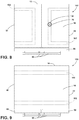
- FIG. 8 is a bottom plan view of the appliance of FIG. 5 ;
- FIG. 9 is a top plan view of the appliance of FIG. 5 ;
- FIG. 10 is a rear top perspective view of another appliance of the present disclosure.
- FIG. 11 is a top partial elevational cross-sectional view of a portion of the insulation space of an appliance of the present disclosure
- FIG. 11A is a partial elevational view of a filter tube for use with an appliance of the present disclosure
- FIG. 13 is a partial side elevational view of a vacuum port of the present disclosure.
- FIG. 14 is a front elevational view of a vacuum port panel of the present disclosure.
- FIG. 15 is a top plan cross-sectional view of vacuum ports extending through a panel of an appliance of the present disclosure.
- the terms “upper,” “lower,” “right,” “left,” “rear,” “front,” “vertical,” “horizontal,” and derivatives thereof shall relate to the disclosure as oriented in FIG. 1 .
- the term “front” shall refer to the surface of the device closer to an intended viewer of the device, and the term “rear” shall refer to the surface of the device further from the intended viewer of the device.
- the disclosure may assume various alternative orientations, except where expressly specified to the contrary.
- the specific devices and processes illustrated in the attached drawings, and described in the following specification are simply exemplary embodiments of the inventive concepts defined in the appended claims. Hence, specific dimensions and other physical characteristics relating to the embodiments disclosed herein are not to be considered as limiting, unless the claims expressly state otherwise.
- reference numeral 10 generally designates an appliance having an outer wrapper 12 that defines a top wall 14 , a bottom wall 16 , a rear wall 18 , and first and second side walls 20 , 22 and includes an inner liner 24 .
- a trim breaker 26 seals the outer wrapper 12 to the inner liner 24 to define an insulation space 30 .
- a single vacuum port 32 is disposed on each of the top wall 14 , the bottom wall 16 , and the first and second side walls 20 , 22 .
- a plurality of vacuum ports 32 is disposed on the rear wall 18 .
- An insulative material 34 is disposed between the outer wrapper 12 and the inner liner 24 .
- a filter media 40 is disposed proximate each vacuum port 32 such that air can be drawn from the insulation space 30 past the filter media 40 and through each vacuum port 32 .
- the illustrated appliance 10 is a refrigerator assembly that includes French doors 50 , 52 that are pivotally coupled with a refrigerator compartment 54 and operable between open and closed positions.
- the refrigerator assembly also includes a lower pull out drawer 56 that defines a freezer compartment 58 .
- the doors 50 , 52 as illustrated in FIG. 1 , include handles 60 configured to allow a user to move the doors 50 , 52 between open and closed positions.
- the refrigerator compartment 54 and the freezer compartment 58 include shelving 62 , as shown in FIG. 1A , that can be adjusted and moved, depending on consumer preference.
- the outer wrapper 12 of the appliance 10 is generally formed from a metal material, which may be steel, aluminum, etc.
- the inner liner 24 is also constructed from a metal material, which may be steel, aluminum, etc.
- sealed plastics, or other materials that can maintain an airtight seal could also be used in conjunction with the systems, as set forth herein.
- the illustrated embodiment includes a plurality of vacuum ports 32 that are spaced at predetermined positions to draw a sufficient amount of vacuum from areas of the insulation space 30 .
- the additional vacuum ports 32 the total vacuum time to place the insulative material 34 in a vacuum state and draw fluid (in the form of air) from the insulation space 30 is lessened. Consequently, refrigerator assemblies can be constructed at a faster rate and with a greater degree of negative pressure between the inner liner 24 and the outer wrapper 12 .
- Each of the ports 32 include a valve system 70 configured to prevent air from entering the insulation space 30 after the vacuum process has been completed. In the illustrated embodiment of FIGS.
- a vacuum port 32 is disposed on each of the top wall 14 , the bottom wall 16 , the rear wall 18 , and the first and second side walls 20 , 22 .
- more vacuum ports 32 could be disposed on any of the top wall 14 , the bottom wall 16 , the rear wall 18 , and the first and second side walls 20 , 22 to increase the speed in which a negative pressure is obtained within the insulation space 30 .
- the vacuum ports 32 may be removed from certain walls of the appliance 10 .
- the vacuum ports 32 may be omitted from the first and second side walls 20 , 22 .
- additional vacuum ports 32 may be disposed on first and second sides of the top wall 14 proximate the first and second side walls 20 , 22 or on first and second sides of the bottom wall 16 in close proximity to the first and second side walls 20 , 22 .
- more vacuum ports 32 on the rear wall 18 may also be positioned on the outer wrapper 12 to compensate for the loss of a vacuum port 32 of each of the first and second side walls 20 , 22 .
- the valves that make up the vacuum ports 32 are configured to attached with a vacuum hose 80 ( FIG. 13 ) and may include ball valves, butterfly valves, check valves, choke valves, diaphragm valves, gate valves, globe valves, poppet valves, etc.
- a simple crimping solution or an end cap can also be used to close the vacuum hose 80 . It will be understood that any kind and any number of valves may be used and that this disclosure is not limited by any of the valve systems noted above.
- the inner liner 24 and the outer wrapper 12 are connected at the trim breaker 26 generally disposed proximate the opening of the appliance 10 .
- the trim breaker 26 is sealed and airtight such that air can neither escape nor enter into the insulation space 30 between the outer wrapper 12 and the inner liner 24 at the trim breaker 26 .
- the insulative material 34 is disposed throughout the appliance 10 in the insulation space 30 . During assembly of the appliance 10 , the insulative material 34 is poured, or otherwise blown into, the insulation space 30 before the insulation space 30 is sealed airtight.
- the filter media 40 is disposed between the vacuum port 32 and the insulative material 34 .
- the filter media 40 acts to prevent insulative material 34 from being drawn through the vacuum port 32 when a negative pressure is placed on the insulation space 30 . Accordingly, the insulative material 34 is maintained in the insulation space 30 between the outer wrapper 12 and the inner liner 24 as air is drawn from the insulation space 30 by an external vacuum pump.
- the filter media 40 may have a variety of constructions and may be constructed from sintered metal, plastic, etc.
- the filter media 40 , or portions of the filter media 40 may also be constructed from a fiberglass based filter media.
- the pores of the filter media 40 will be dictated by the size of the granules, fibers, or strands that make up the insulative material 34 disposed in the insulation space 30 .
- the pores of the filter media 40 will be smaller than the fibers, strands, or granules of the insulative material 34 . Accordingly, air can be drawn from the insulation space 30 without removing the insulative material 34 after the insulative material 34 is installed between the inner liner 24 and the outer wrapper 12 .
- the illustrated appliance 100 includes a plurality of channels 102 that are in fluid communication with each vacuum port 32 .
- the channels 102 are disposed on each of the rear wall 18 and the bottom wall 16 .
- the channels 102 are configured to extend to distal corners 104 of the rear wall 18 and distal corners 106 of the bottom wall 16 . Accordingly, when the insulation space 30 is being vacuumed at the vacuum port 32 , air is drawn through the channels 102 from the insulation space 30 and out the vacuum port 32 .
- the filter media 40 is elongate and disposed along each of the channels 102 to prevent the insulative material 34 from entering into the channel 102 and being withdrawn from the vacuum port 32 .
- the filter media 40 may include a relatively elongate, planar filter screen formed from a sintered metal, porous plastic, or fiberglass material that extends along the entire length of each channel 102 .
- the channel 102 is defined from a protruding outer casing 110 that protrudes from a planar extent of the rear wall 18 and the bottom wall 16 .
- the casing 110 may be integrally formed with a wall of the appliance 10 , or may be sealingly coupled with a wall of the appliance 10 via welding, adhesives, mechanical gaskets, etc.
- the casing 110 may include an arcuate cross-section, as shown, or have a square, triangular, etc. cross-section.
- the channel 102 draws air through the filter media 40 of the planar filter screen, while maintaining the insulative material 34 within the insulation space 30 . It will be understood that the filter media 40 may be any of a number of variety of shapes and does not necessarily need to be flat.
- the filter media 40 for this assembly includes an elongate filter screen having a curved cross-section.
- the planar extent of the rear wall 18 and/or the bottom wall 16 forms a first portion of the channel 102 .
- the filter media 40 in the form of the elongate filter screen forms a second portion of the channel 102 .
- the channels 102 although shown in a linear configuration, may also have a curved shape or a circular shape that extends about the bottom wall 16 and the rear wall 18 .
- the channels 102 could also include multiple branches that extend at any angle from the channels 102 .
- the channels may be disposed on any of the walls of the appliance 10 and are not limited to the rear wall 18 and the bottom wall 16 .
- the channels 102 are disposed on the back wall and the bottom wall 16 as these are typically portions of the appliance 10 that are not exposed to the consumer. Accordingly, the first and second side walls 20 , 22 can be exposed with no apparent additional structure that relates to the vacuuming process disposed thereon.
- the illustrated appliance 10 includes the channel 102 extending in a loop configuration.
- the channel includes one vacuum port 32 , which, in this instance is disposed on the bottom wall 16 of the appliance 10 .
- the channel 102 extends about the bottom wall 16 , the first side wall 20 , the top wall 14 , the second side wall 22 , and back to the bottom wall 16 , before returning to the second side wall 22 , the top wall 14 , and the first side wall 20 and back to the bottom wall 16 .
- negative pressure is obtained within the insulation space 30 when the vacuum port 32 is operably coupled with the external vacuum system.
- Air is then drawn through the channel 102 , which extends through each of the four walls between the outer wrapper 12 and the inner liner 24 until a suitable negative pressure has been reached.
- the loop configuration for drawing air from the appliance 10 is not limited to the configuration shown.
- another looped channel could extend about the back wall and could be operably coupled with the loop shown in FIGS. 5-9 , or could be a separate loop with a separate vacuum port 32 , which may depend on the needed speed and negative pressure that is desirable for the insulation space 30 of the appliance 10 .
- the channels 102 of the appliance 10 may protrude from one or more of the walls, as shown in FIG. 3C , or may be formed within the insulative material 34 in the insulation space 30 of the appliance 10 .
- an appliance 200 is illustrated having channels 202 are again applied to the insulation space 30 between the inner liner 24 and the outer wrapper 12 .
- the channels 202 extends along edges 204 and vertices 206 of adjacent and joined walls of the outer wrapper 12 .
- one channel 202 is looped about a periphery of the second side wall 22 , starting at the edge 204 defined by the second side wall 22 and the bottom wall 16 , extending upward at the edge 204 defined by the front of the second side wall 22 , the edge 204 defined between the second side wall 22 and the top wall 14 , the edge 204 defined between the second side wall 22 and the rear wall 18 , and back to the second side wall 22 and the bottom wall 16 .
- This looped channel 102 is in fluid communication with a looped channel 102 extending about the periphery of the rear wall 18 and the vacuum port 32 .
- the looped channel 102 extending about the periphery of the rear wall 18 starts at the edge 204 defined between the second side wall 22 and the rear wall 18 , the edge 204 extending between the top wall 14 and the rear wall 18 , the edge 204 extending between the first side wall 20 and the rear wall 18 , and returning to the vacuum port 32 by way of the edge 204 extending between the bottom wall 16 and the rear wall 18 .
- a permeable filter tube 210 having a multitude of perforations 212 may be disposed along the edges 204 of joined walls, with the permeable filter tube 210 being in fluid communication with the vacuum port 32 .
- the permeable filter tube 210 extends along multiple edges 204 and vertices 206 before terminating at the vacuum port 32 .
- the permeable filter tube 210 may be coupled with an interior surface 214 of one or more of the walls 14 , 16 , 18 , 20 , 22 of the outer wrapper 12 .
- the permeable filter tube 210 may be constructed from a sintered metal, porous plastic, or fiberglass material, for example, that allows air to be withdrawn from the insulation space 30 without removing the insulative material 34 .
- Other air permeable structures may also be used to filter air from the insulation space 30 without removing the insulative material 34 .
- the channel 202 may be formed in an edge space 220 defined between the edge 204 of the appliance 10 and the filter media 40 that prevents the insulative material 34 from entering into the channel 202 .
- the channels 202 extend along the edge spaces 220 and eventually terminate at the vacuum port 32 located at a bottom of the rear wall 18 .
- the filter media 40 is curvilinear outward (convex) and prevents the insulative material 34 from entering into the channel 202 .
- the filter media 40 may be flat, or may be concave inward toward the insulative material 34 .
- the structure of the channels 202 may depend upon the needed construction time determined for a particular appliance.
- the vacuum ports 32 are in fluid communication with the channels 202 and may include a vacuum port panel 230 having apertures 232 for receiving and securing the vacuum ports 32 . that places all of the vacuum ports 32 in close proximity.
- the vacuum port 32 includes a valve that is configured to allow air to escape from the vacuum port 32 , but not enter into the vacuum port 32 from the environment.
- the channels 202 extend in a variety of directions generally directed at distal vertices of the appliance 10 .
- the filter media 40 may include any of a variety of materials, including sintered material (metal, stainless steel, steel, alloys, aluminum, stone, ceramic, etc.), porous plastic, permeable fiberglass, etc.
- sintered material metal, stainless steel, steel, alloys, aluminum, stone, ceramic, etc.
- porous plastic permeable fiberglass, etc.
- the term “coupled” in all of its form, couple, coupling, coupled, etc. generally means the joining of two components (electrical or mechanical) directly or indirectly to one another. Such joining may be stationary in nature or movable in nature. Such joining may be achieved with the two components (electrical or mechanical) and any additional intermediate members being integrally formed as a single unitary body with one another or with the two components. Such joining may be permanent in nature or may be removable or releasable in nature unless otherwise stated.
- elements shown as integrally formed may be constructed of multiple parts or elements shown as multiple parts may be integrally formed, the operation of the interfaces may be reversed or otherwise varied, the length or width of the structures and/or members or connector or other elements of the system may be varied, the nature or number of adjustment positions provided between the elements may be varied.
- the elements and/or assemblies of the system may be constructed from any of a wide variety of materials that provide sufficient strength or durability, in any of a wide variety of colors, textures, and combinations. Accordingly, all such modifications are intended to be included within the scope of the present innovations. Other substitutions, modifications, changes, and omissions may be made in the design, operating conditions, and arrangement of the desired and other exemplary embodiments without departing from the spirit of the present innovations.
Landscapes
- Engineering & Computer Science (AREA)
- General Engineering & Computer Science (AREA)
- Mechanical Engineering (AREA)
- Chemical & Material Sciences (AREA)
- Combustion & Propulsion (AREA)
- Physics & Mathematics (AREA)
- Thermal Sciences (AREA)
- Thermal Insulation (AREA)
- Refrigerator Housings (AREA)
Abstract
Description
Claims (20)
Applications Claiming Priority (1)
| Application Number | Priority Date | Filing Date | Title |
|---|---|---|---|
| PCT/US2017/013940 WO2018136054A1 (en) | 2017-01-18 | 2017-01-18 | Use of rigid or permeable conduits for achieving faster vacuum evacuation time in vacuum insulated structures |
Publications (2)
| Publication Number | Publication Date |
|---|---|
| US20190285336A1 US20190285336A1 (en) | 2019-09-19 |
| US11029080B2 true US11029080B2 (en) | 2021-06-08 |
Family
ID=62908266
Family Applications (1)
| Application Number | Title | Priority Date | Filing Date |
|---|---|---|---|
| US16/302,923 Active 2037-06-01 US11029080B2 (en) | 2017-01-18 | 2017-01-18 | Use of rigid or permeable conduits for achieving faster vacuum evacuation time in vacuum insulated structures |
Country Status (3)
| Country | Link |
|---|---|
| US (1) | US11029080B2 (en) |
| EP (1) | EP3571452B1 (en) |
| WO (1) | WO2018136054A1 (en) |
Cited By (3)
| Publication number | Priority date | Publication date | Assignee | Title |
|---|---|---|---|---|
| US11300239B2 (en) * | 2018-09-28 | 2022-04-12 | Whirlpool Corporation | Channel system for a vacuum insulated structure |
| US11519661B2 (en) | 2017-01-18 | 2022-12-06 | Whirlpool Corporation | Increased vacuum port area for achieving faster vacuum evacuation time in vacuum insulated structures |
| US11708935B2 (en) | 2021-01-12 | 2023-07-25 | Whirlpool Corporation | Vacuum insulated refrigerator structure with feature for controlling deformation and improved air withdrawal |
Families Citing this family (6)
| Publication number | Priority date | Publication date | Assignee | Title |
|---|---|---|---|---|
| EP3523584B1 (en) * | 2016-10-04 | 2022-08-24 | Whirlpool Corporation | Structural formations incorporated within a vacuum insulated structure |
| CN208075410U (en) * | 2017-11-27 | 2018-11-09 | 博西华电器(江苏)有限公司 | Refrigerating appliance |
| US10697696B1 (en) * | 2019-02-25 | 2020-06-30 | Whirlpool Corporation | Vacuum insulated structure with internal airway system |
| US10605520B1 (en) | 2019-03-25 | 2020-03-31 | Whirlpool Corporation | Vacuum insulation assembly for an appliance |
| US11021905B1 (en) * | 2019-12-17 | 2021-06-01 | Whirlpool Corporation | Insulated door assembly |
| US11614271B2 (en) | 2020-12-29 | 2023-03-28 | Whirlpool Corporation | Vacuum insulated structure with sheet metal features to control vacuum bow |
Citations (44)
| Publication number | Priority date | Publication date | Assignee | Title |
|---|---|---|---|---|
| US2128336A (en) | 1936-03-25 | 1938-08-30 | Torstensson Sture Folke | Insulation |
| GB730146A (en) | 1952-07-30 | 1955-05-18 | Gen Electric | Improvements in and relating to insulating structures |
| US3010262A (en) | 1958-10-08 | 1961-11-28 | Jr Herbert Rumsey | Method of making packages wrapped in flexible sheet material |
| US3052019A (en) | 1960-06-10 | 1962-09-04 | Bell Aerospace Corp | Insulation |
| US3358059A (en) | 1964-04-20 | 1967-12-12 | Dow Chemical Co | Method of filling enclosures with low density particulated material |
| US3739936A (en) * | 1971-09-17 | 1973-06-19 | Gen Electric | Pour hole closure for foam mold |
| US4132755A (en) | 1977-07-22 | 1979-01-02 | Jay Johnson | Process for manufacturing resin-impregnated, reinforced articles without the presence of resin fumes |
| JPH04366094A (en) | 1991-06-13 | 1992-12-17 | Kubota Corp | Powder vacuum insulator |
| US5252408A (en) * | 1990-09-24 | 1993-10-12 | Aladdin Industries, Inc. | Vacuum insulated panel and method of forming a vacuum insulated panel |
| EP0587548A1 (en) | 1992-09-10 | 1994-03-16 | ELECTROLUX RESEARCH & INNOVATION AB | Insulation for refrigerators or freezers |
| US5500305A (en) | 1990-09-24 | 1996-03-19 | Aladdin Industries, Inc. | Vacuum insulated panel and method of making a vacuum insulated panel |
| US5509248A (en) * | 1993-09-29 | 1996-04-23 | Aktiebolaget Electrolux | Method for filling and packing insulating powder in the walls of a cabinet body |
| US5512345A (en) * | 1994-03-28 | 1996-04-30 | Kabushiki Kaisha Toshiba | Vacuum insulator casing and method of making vacuum insulator panel |
| US5586680A (en) | 1993-12-22 | 1996-12-24 | Aktiebolaget Electrolux | Box constituting vacuum insulated walls of a refrigerator or freezer cabinet |
| EP0757136A1 (en) | 1995-08-01 | 1997-02-05 | HOESCH SIEGERLANDWERKE GmbH | Sandwich panel-type for construction of heat isolated supporting walls, roofs and floors |
| WO1998029309A1 (en) | 1996-12-23 | 1998-07-09 | Vacupanel, Inc. | Vacuum insulated panel, container and production method |
| EP0857928A1 (en) | 1997-02-07 | 1998-08-12 | BSH Bosch und Siemens Hausgeräte GmbH | Heat insulated housing |
| US5827385A (en) | 1994-07-15 | 1998-10-27 | Vacupanel, Inc. | Method of producing an evacuated insulated container |
| US6090335A (en) | 1999-01-08 | 2000-07-18 | Northrop Grumman Corporation | Process of forming fiber reinforced composite articles using an insitu cured resin infusion port |
| US6109712A (en) | 1998-07-16 | 2000-08-29 | Maytag Corporation | Integrated vacuum panel insulation for thermal cabinet structures |
| EP1335171A1 (en) | 2002-02-07 | 2003-08-13 | Whirlpool Corporation | Domestic refrigerator and procedure for producing the same |
| WO2003081152A1 (en) | 2002-03-25 | 2003-10-02 | Arçelik A.S. | An insulated unit and production method thereof |
| US6656411B1 (en) | 1999-01-11 | 2003-12-02 | Northrop Grumman Corporation | Grooved core pattern for optimum resin distribution |
| WO2005093349A1 (en) | 2004-03-22 | 2005-10-06 | Arcelik Anonim Sirketi | A cooling device and a method for improving insulation |
| US20050235682A1 (en) | 2002-03-13 | 2005-10-27 | Chie Hirai | Refrigerator |
| US20090038244A1 (en) * | 2006-02-07 | 2009-02-12 | Tilmann Kuhn | Splinter protection with optical and thermal functionality |
| JP4366093B2 (en) | 2003-02-14 | 2009-11-18 | キヤノン株式会社 | Look-up table creation method, computer program, and imaging apparatus |
| US20100136231A1 (en) | 2007-04-10 | 2010-06-03 | BSH Bosch und Siemens Hausgeräte GmbH | Method for producing a refrigeration device |
| US20120104923A1 (en) * | 2010-10-28 | 2012-05-03 | Lg Electronics Inc. | Refrigerator comprising vacuum space |
| US8298473B2 (en) | 2009-05-15 | 2012-10-30 | The Boeing Company | Method of making a cure tool with integrated edge breather |
| US20130257257A1 (en) * | 2012-04-02 | 2013-10-03 | Whirlpool Corporation | Method to create vacuum insulated cabinets for refrigerators |
| US8678530B2 (en) | 2011-04-25 | 2014-03-25 | General Electric Company | Foam manifold for injection molding consumer appliance case, foamed-in case, and related method |
| US20140346942A1 (en) * | 2013-05-22 | 2014-11-27 | Lg Electronics Inc. | Refrigerator and method of manufacturing the same |
| US8944541B2 (en) | 2012-04-02 | 2015-02-03 | Whirlpool Corporation | Vacuum panel cabinet structure for a refrigerator |
| US9132592B2 (en) * | 2012-11-19 | 2015-09-15 | General Electric Company | Appliance with expanding foam material |
| US20170159999A1 (en) | 2015-12-08 | 2017-06-08 | Whirlpool Corporation | Insulation structure for an appliance having a uniformly mixed multi-component insulation material, and a method for even distribution of material combinations therein |
| US20170160001A1 (en) * | 2015-12-08 | 2017-06-08 | Whirlpool Corporation | Insulation structure for an appliance having a uniformly mixed multi-component insulation material, and a method for even distribution of material combinations therein |
| US20170276287A1 (en) * | 2015-04-06 | 2017-09-28 | Panasonic Intellectual Property Management Co., Ltd. | Vacuum heat insulation body |
| US10220605B2 (en) * | 2015-11-10 | 2019-03-05 | The Boeing Company | Edge breathers for composite products |
| US20190128592A1 (en) | 2016-04-15 | 2019-05-02 | Whirlpool Corporation | Vacuum insulated refrigerator cabinet |
| US20190145697A1 (en) * | 2017-01-18 | 2019-05-16 | Whirlpool Corporation | Use of multiple port locations for achieving faster vacuum evacuation time in vacuum insulated structures |
| US20190293339A1 (en) * | 2016-09-26 | 2019-09-26 | Whirlpool Corporation | Vacuum generating system for an appliance incorporating a vacuum insulated structure |
| US10605520B1 (en) * | 2019-03-25 | 2020-03-31 | Whirlpool Corporation | Vacuum insulation assembly for an appliance |
| US20200103067A1 (en) * | 2018-09-28 | 2020-04-02 | Whirlpool Corporation | Channel system for a vacuum insulated structure |
-
2017
- 2017-01-18 WO PCT/US2017/013940 patent/WO2018136054A1/en unknown
- 2017-01-18 US US16/302,923 patent/US11029080B2/en active Active
- 2017-01-18 EP EP17892435.3A patent/EP3571452B1/en active Active
Patent Citations (45)
| Publication number | Priority date | Publication date | Assignee | Title |
|---|---|---|---|---|
| US2128336A (en) | 1936-03-25 | 1938-08-30 | Torstensson Sture Folke | Insulation |
| GB730146A (en) | 1952-07-30 | 1955-05-18 | Gen Electric | Improvements in and relating to insulating structures |
| US3010262A (en) | 1958-10-08 | 1961-11-28 | Jr Herbert Rumsey | Method of making packages wrapped in flexible sheet material |
| US3052019A (en) | 1960-06-10 | 1962-09-04 | Bell Aerospace Corp | Insulation |
| US3358059A (en) | 1964-04-20 | 1967-12-12 | Dow Chemical Co | Method of filling enclosures with low density particulated material |
| US3739936A (en) * | 1971-09-17 | 1973-06-19 | Gen Electric | Pour hole closure for foam mold |
| US4132755A (en) | 1977-07-22 | 1979-01-02 | Jay Johnson | Process for manufacturing resin-impregnated, reinforced articles without the presence of resin fumes |
| US5500305A (en) | 1990-09-24 | 1996-03-19 | Aladdin Industries, Inc. | Vacuum insulated panel and method of making a vacuum insulated panel |
| US5252408A (en) * | 1990-09-24 | 1993-10-12 | Aladdin Industries, Inc. | Vacuum insulated panel and method of forming a vacuum insulated panel |
| JPH04366094A (en) | 1991-06-13 | 1992-12-17 | Kubota Corp | Powder vacuum insulator |
| EP0587548A1 (en) | 1992-09-10 | 1994-03-16 | ELECTROLUX RESEARCH & INNOVATION AB | Insulation for refrigerators or freezers |
| US5509248A (en) * | 1993-09-29 | 1996-04-23 | Aktiebolaget Electrolux | Method for filling and packing insulating powder in the walls of a cabinet body |
| US5586680A (en) | 1993-12-22 | 1996-12-24 | Aktiebolaget Electrolux | Box constituting vacuum insulated walls of a refrigerator or freezer cabinet |
| US5512345A (en) * | 1994-03-28 | 1996-04-30 | Kabushiki Kaisha Toshiba | Vacuum insulator casing and method of making vacuum insulator panel |
| US5827385A (en) | 1994-07-15 | 1998-10-27 | Vacupanel, Inc. | Method of producing an evacuated insulated container |
| EP0757136A1 (en) | 1995-08-01 | 1997-02-05 | HOESCH SIEGERLANDWERKE GmbH | Sandwich panel-type for construction of heat isolated supporting walls, roofs and floors |
| WO1998029309A1 (en) | 1996-12-23 | 1998-07-09 | Vacupanel, Inc. | Vacuum insulated panel, container and production method |
| EP0857928A1 (en) | 1997-02-07 | 1998-08-12 | BSH Bosch und Siemens Hausgeräte GmbH | Heat insulated housing |
| US6109712A (en) | 1998-07-16 | 2000-08-29 | Maytag Corporation | Integrated vacuum panel insulation for thermal cabinet structures |
| US6090335A (en) | 1999-01-08 | 2000-07-18 | Northrop Grumman Corporation | Process of forming fiber reinforced composite articles using an insitu cured resin infusion port |
| US6656411B1 (en) | 1999-01-11 | 2003-12-02 | Northrop Grumman Corporation | Grooved core pattern for optimum resin distribution |
| EP1335171A1 (en) | 2002-02-07 | 2003-08-13 | Whirlpool Corporation | Domestic refrigerator and procedure for producing the same |
| US20050235682A1 (en) | 2002-03-13 | 2005-10-27 | Chie Hirai | Refrigerator |
| WO2003081152A1 (en) | 2002-03-25 | 2003-10-02 | Arçelik A.S. | An insulated unit and production method thereof |
| JP4366093B2 (en) | 2003-02-14 | 2009-11-18 | キヤノン株式会社 | Look-up table creation method, computer program, and imaging apparatus |
| WO2005093349A1 (en) | 2004-03-22 | 2005-10-06 | Arcelik Anonim Sirketi | A cooling device and a method for improving insulation |
| US20090038244A1 (en) * | 2006-02-07 | 2009-02-12 | Tilmann Kuhn | Splinter protection with optical and thermal functionality |
| US20100136231A1 (en) | 2007-04-10 | 2010-06-03 | BSH Bosch und Siemens Hausgeräte GmbH | Method for producing a refrigeration device |
| US8298473B2 (en) | 2009-05-15 | 2012-10-30 | The Boeing Company | Method of making a cure tool with integrated edge breather |
| US20120104923A1 (en) * | 2010-10-28 | 2012-05-03 | Lg Electronics Inc. | Refrigerator comprising vacuum space |
| US8678530B2 (en) | 2011-04-25 | 2014-03-25 | General Electric Company | Foam manifold for injection molding consumer appliance case, foamed-in case, and related method |
| US8944541B2 (en) | 2012-04-02 | 2015-02-03 | Whirlpool Corporation | Vacuum panel cabinet structure for a refrigerator |
| US20130257257A1 (en) * | 2012-04-02 | 2013-10-03 | Whirlpool Corporation | Method to create vacuum insulated cabinets for refrigerators |
| US9132592B2 (en) * | 2012-11-19 | 2015-09-15 | General Electric Company | Appliance with expanding foam material |
| US20140346942A1 (en) * | 2013-05-22 | 2014-11-27 | Lg Electronics Inc. | Refrigerator and method of manufacturing the same |
| US20170276287A1 (en) * | 2015-04-06 | 2017-09-28 | Panasonic Intellectual Property Management Co., Ltd. | Vacuum heat insulation body |
| US10220605B2 (en) * | 2015-11-10 | 2019-03-05 | The Boeing Company | Edge breathers for composite products |
| US20170159999A1 (en) | 2015-12-08 | 2017-06-08 | Whirlpool Corporation | Insulation structure for an appliance having a uniformly mixed multi-component insulation material, and a method for even distribution of material combinations therein |
| US20170160001A1 (en) * | 2015-12-08 | 2017-06-08 | Whirlpool Corporation | Insulation structure for an appliance having a uniformly mixed multi-component insulation material, and a method for even distribution of material combinations therein |
| US20190128592A1 (en) | 2016-04-15 | 2019-05-02 | Whirlpool Corporation | Vacuum insulated refrigerator cabinet |
| US20190293339A1 (en) * | 2016-09-26 | 2019-09-26 | Whirlpool Corporation | Vacuum generating system for an appliance incorporating a vacuum insulated structure |
| US20190145697A1 (en) * | 2017-01-18 | 2019-05-16 | Whirlpool Corporation | Use of multiple port locations for achieving faster vacuum evacuation time in vacuum insulated structures |
| US20200103067A1 (en) * | 2018-09-28 | 2020-04-02 | Whirlpool Corporation | Channel system for a vacuum insulated structure |
| US10746343B2 (en) * | 2018-09-28 | 2020-08-18 | Whirlpool Corporation | Channel system for a vacuum insulated structure |
| US10605520B1 (en) * | 2019-03-25 | 2020-03-31 | Whirlpool Corporation | Vacuum insulation assembly for an appliance |
Non-Patent Citations (1)
| Title |
|---|
| Human translation from German to English of EP0857928A1 (Year: 2021). * |
Cited By (4)
| Publication number | Priority date | Publication date | Assignee | Title |
|---|---|---|---|---|
| US11519661B2 (en) | 2017-01-18 | 2022-12-06 | Whirlpool Corporation | Increased vacuum port area for achieving faster vacuum evacuation time in vacuum insulated structures |
| US11300239B2 (en) * | 2018-09-28 | 2022-04-12 | Whirlpool Corporation | Channel system for a vacuum insulated structure |
| US11692663B2 (en) | 2018-09-28 | 2023-07-04 | Whirlpool Corporation | Channel system for a vacuum insulated structure |
| US11708935B2 (en) | 2021-01-12 | 2023-07-25 | Whirlpool Corporation | Vacuum insulated refrigerator structure with feature for controlling deformation and improved air withdrawal |
Also Published As
| Publication number | Publication date |
|---|---|
| EP3571452A4 (en) | 2020-09-02 |
| EP3571452A1 (en) | 2019-11-27 |
| US20190285336A1 (en) | 2019-09-19 |
| WO2018136054A1 (en) | 2018-07-26 |
| EP3571452B1 (en) | 2023-04-19 |
Similar Documents
| Publication | Publication Date | Title |
|---|---|---|
| US11035607B2 (en) | Use of multiple port locations for achieving faster vacuum evacuation time in vacuum insulated structures | |
| US11029080B2 (en) | Use of rigid or permeable conduits for achieving faster vacuum evacuation time in vacuum insulated structures | |
| US11519661B2 (en) | Increased vacuum port area for achieving faster vacuum evacuation time in vacuum insulated structures | |
| US11692663B2 (en) | Channel system for a vacuum insulated structure | |
| US11248734B2 (en) | Structural cabinet for an appliance incorporating unitary metallic boxes | |
| US11650003B2 (en) | Vacuum generating system for an appliance incorporating a vacuum insulated structure | |
| CN102454789B (en) | Sealing member, vacuum chamber and refrigerating plant | |
| US11767945B2 (en) | Vacuum insulated structure with filter features in a vacuum cavity | |
| KR20180136533A (en) | Door seal and refrigeration container having same | |
| US11009284B2 (en) | Vacuum insulated refrigerator structure with three dimensional characteristics | |
| US20240085093A1 (en) | Vacuum insulated door structure for an appliance incorporating a dispenser structure | |
| CN205002495U (en) | Refrigerator and door seals subassembly thereof | |
| WO2022000742A1 (en) | Refrigerator | |
| WO2022000741A1 (en) | Refrigerator | |
| JPS6018785Y2 (en) | refrigerator |
Legal Events
| Date | Code | Title | Description |
|---|---|---|---|
| AS | Assignment |
Owner name: WHIRLPOOL CORPORATION, MICHIGAN Free format text: ASSIGNMENT OF ASSIGNORS INTEREST;ASSIGNORS:NAIK, ABHAY;SHANNIGRAHI, SUBRATA;SIGNING DATES FROM 20181106 TO 20181108;REEL/FRAME:047544/0055 |
|
| FEPP | Fee payment procedure |
Free format text: ENTITY STATUS SET TO UNDISCOUNTED (ORIGINAL EVENT CODE: BIG.); ENTITY STATUS OF PATENT OWNER: LARGE ENTITY |
|
| STPP | Information on status: patent application and granting procedure in general |
Free format text: DOCKETED NEW CASE - READY FOR EXAMINATION |
|
| STPP | Information on status: patent application and granting procedure in general |
Free format text: NON FINAL ACTION MAILED |
|
| STPP | Information on status: patent application and granting procedure in general |
Free format text: NOTICE OF ALLOWANCE MAILED -- APPLICATION RECEIVED IN OFFICE OF PUBLICATIONS |
|
| AS | Assignment |
Owner name: WHIRLPOOL CORPORATION, MICHIGAN Free format text: ASSIGNMENT OF ASSIGNORS INTEREST;ASSIGNOR:FRATTINI, GUSTAVO;REEL/FRAME:056088/0650 Effective date: 20210428 |
|
| STPP | Information on status: patent application and granting procedure in general |
Free format text: AWAITING TC RESP, ISSUE FEE PAYMENT RECEIVED Free format text: PUBLICATIONS -- ISSUE FEE PAYMENT RECEIVED |
|
| STPP | Information on status: patent application and granting procedure in general |
Free format text: AWAITING TC RESP, ISSUE FEE PAYMENT VERIFIED |
|
| STPP | Information on status: patent application and granting procedure in general |
Free format text: PUBLICATIONS -- ISSUE FEE PAYMENT VERIFIED |
|
| STCF | Information on status: patent grant |
Free format text: PATENTED CASE |