US11026136B2 - Handovers with simplified network topology - Google Patents
Handovers with simplified network topology Download PDFInfo
- Publication number
- US11026136B2 US11026136B2 US15/721,728 US201715721728A US11026136B2 US 11026136 B2 US11026136 B2 US 11026136B2 US 201715721728 A US201715721728 A US 201715721728A US 11026136 B2 US11026136 B2 US 11026136B2
- Authority
- US
- United States
- Prior art keywords
- handover
- base station
- security key
- core network
- handover request
- Prior art date
- Legal status (The legal status is an assumption and is not a legal conclusion. Google has not performed a legal analysis and makes no representation as to the accuracy of the status listed.)
- Active
Links
Images


Classifications
-
- H—ELECTRICITY
- H04—ELECTRIC COMMUNICATION TECHNIQUE
- H04W—WIRELESS COMMUNICATION NETWORKS
- H04W36/00—Hand-off or reselection arrangements
- H04W36/0005—Control or signalling for completing the hand-off
- H04W36/0055—Transmission or use of information for re-establishing the radio link
- H04W36/0061—Transmission or use of information for re-establishing the radio link of neighbour cell information
-
- H—ELECTRICITY
- H04—ELECTRIC COMMUNICATION TECHNIQUE
- H04W—WIRELESS COMMUNICATION NETWORKS
- H04W24/00—Supervisory, monitoring or testing arrangements
- H04W24/02—Arrangements for optimising operational condition
-
- H—ELECTRICITY
- H04—ELECTRIC COMMUNICATION TECHNIQUE
- H04W—WIRELESS COMMUNICATION NETWORKS
- H04W36/00—Hand-off or reselection arrangements
- H04W36/0005—Control or signalling for completing the hand-off
- H04W36/0011—Control or signalling for completing the hand-off for data sessions of end-to-end connection
- H04W36/0033—Control or signalling for completing the hand-off for data sessions of end-to-end connection with transfer of context information
- H04W36/0038—Control or signalling for completing the hand-off for data sessions of end-to-end connection with transfer of context information of security context information
-
- H—ELECTRICITY
- H04—ELECTRIC COMMUNICATION TECHNIQUE
- H04W—WIRELESS COMMUNICATION NETWORKS
- H04W36/00—Hand-off or reselection arrangements
- H04W36/0005—Control or signalling for completing the hand-off
- H04W36/0055—Transmission or use of information for re-establishing the radio link
- H04W36/0064—Transmission or use of information for re-establishing the radio link of control information between different access points
-
- H—ELECTRICITY
- H04—ELECTRIC COMMUNICATION TECHNIQUE
- H04W—WIRELESS COMMUNICATION NETWORKS
- H04W36/00—Hand-off or reselection arrangements
- H04W36/0005—Control or signalling for completing the hand-off
- H04W36/0055—Transmission or use of information for re-establishing the radio link
- H04W36/0066—Transmission or use of information for re-establishing the radio link of control information between different types of networks in order to establish a new radio link in the target network
-
- H—ELECTRICITY
- H04—ELECTRIC COMMUNICATION TECHNIQUE
- H04W—WIRELESS COMMUNICATION NETWORKS
- H04W36/00—Hand-off or reselection arrangements
- H04W36/14—Reselecting a network or an air interface
-
- H—ELECTRICITY
- H04—ELECTRIC COMMUNICATION TECHNIQUE
- H04W—WIRELESS COMMUNICATION NETWORKS
- H04W48/00—Access restriction; Network selection; Access point selection
- H04W48/16—Discovering, processing access restriction or access information
-
- H—ELECTRICITY
- H04—ELECTRIC COMMUNICATION TECHNIQUE
- H04W—WIRELESS COMMUNICATION NETWORKS
- H04W36/00—Hand-off or reselection arrangements
- H04W36/0005—Control or signalling for completing the hand-off
- H04W36/0055—Transmission or use of information for re-establishing the radio link
-
- H—ELECTRICITY
- H04—ELECTRIC COMMUNICATION TECHNIQUE
- H04W—WIRELESS COMMUNICATION NETWORKS
- H04W84/00—Network topologies
- H04W84/18—Self-organising networks, e.g. ad-hoc networks or sensor networks
-
- H—ELECTRICITY
- H04—ELECTRIC COMMUNICATION TECHNIQUE
- H04W—WIRELESS COMMUNICATION NETWORKS
- H04W88/00—Devices specially adapted for wireless communication networks, e.g. terminals, base stations or access point devices
- H04W88/12—Access point controller devices
-
- H—ELECTRICITY
- H04—ELECTRIC COMMUNICATION TECHNIQUE
- H04W—WIRELESS COMMUNICATION NETWORKS
- H04W88/00—Devices specially adapted for wireless communication networks, e.g. terminals, base stations or access point devices
- H04W88/16—Gateway arrangements
-
- H—ELECTRICITY
- H04—ELECTRIC COMMUNICATION TECHNIQUE
- H04W—WIRELESS COMMUNICATION NETWORKS
- H04W92/00—Interfaces specially adapted for wireless communication networks
- H04W92/04—Interfaces between hierarchically different network devices
- H04W92/045—Interfaces between hierarchically different network devices between access point and backbone network device
-
- H—ELECTRICITY
- H04—ELECTRIC COMMUNICATION TECHNIQUE
- H04W—WIRELESS COMMUNICATION NETWORKS
- H04W92/00—Interfaces specially adapted for wireless communication networks
- H04W92/16—Interfaces between hierarchically similar devices
- H04W92/20—Interfaces between hierarchically similar devices between access points
Definitions
- 3GPP TS 33.401 and TS 36.423 are hereby incorporated by reference in their entirety for all purposes.
- LTE small cells will slowly and steadily fill the gaps in the LTE coverage provided by macros. These cells will also augment the overall capacity of the network in terms of throughput. They are inexpensive, easier to deploy and operate. However, they need to connect to a gateway device to reach the core network. Without a gateway device, the sheer number of small cells will overwhelm the core network with signaling traffic. An intelligent gateway device can significantly reduce signaling traffic for the core network by performing virtualization and topology hiding.
- a method comprising: at a coordinating gateway during a handover of a mobile device from a first base station to a second base station, receiving a first handover request from the first base station; discarding a first shared security key received in the first handover request; sending a tunnel switching request to a core network node; obtaining precursors for a second shared security key from the core network node in a response to the switching request; sending a second handover request to the second base station with the precursors to calculate the second shared security key for securing a data connection for the mobile device following the handover; deriving the second shared security key from the obtained precursors at the first base station; and deriving the second shared security key from the obtained precursors at the coordinating gateway.
- the core network node may be a mobility management entity (MME) in a Long Term Evolution (LTE) network
- the first handover request may be an X2 handover request
- the second handover request may be an S1 handover request.
- the tunnel switching request may be an S1 path switch message, and
- the precursors may be next hop (NH) and next hop chaining count (NCC) values.
- the first shared security key and the second shared security key may be KeNB* keys.
- the method may further comprise caching data between sending the tunnel switching request and completing the second handover request.
- the method may further comprise, at the coordinating gateway, proxying the core network node to the second base station and proxying the second base station to the core network node.
- the method may further comprise proxying the core network node to the second base station by providing a mobility management entity (MME) functionality at the coordinating gateway, and proxying the second base station to the core network node by providing a base station interface to the core network node at the coordinating gateway.
- MME mobility management entity
- the method may further comprise deriving the second shared security key from the obtained precursors using a carrier frequency of the second base station and a cell identifier of the second base station.
- the carrier frequency may be an EARFCN.
- a method comprising: at a coordinating gateway during a handover of a mobile device from a first base station to a second base station, the coordinating gateway providing proxy services to the first base station, obtaining a first security key for the mobile device from a core network node during an attach procedure for the mobile device to the core network node; receiving a first handover request from the first base station; calculating a second security key based on the first security key, a carrier frequency of the second base station, and a cell identifier of the second base station; and sending a second handover request to the second base station with the second security key for securing a data connection for the mobile device following the handover.
- the core network node may be a mobility management entity (MME) in a Long Term Evolution (LTE) network
- the first handover request may be an X2 handover request and
- the second handover request may be an S1 handover request.
- the carrier frequency may be an Evolved Absolute Radio Frequency Channel Number (EARFCN) and the cell identifier may be a physical cell identifier (PCI).
- the method may further comprise obtaining the carrier frequency and the cell identifier of the second base station during a prior handover involving the second base station and the coordinating gateway.
- the first shared security key may be a KeNB key and the second shared security key may be a KeNB* key.
- the method may further comprise caching data between receiving the first handover request and completing the second handover request.
- the method may further comprise, at the coordinating gateway, proxying the core network node to the second base station and proxying the second base station to the core network node.
- the method may further comprise proxying the core network node to the second base station by providing a mobility management entity (MME) functionality at the coordinating gateway, and proxying the second base station to the core network node by providing a base station interface to the core network node at the coordinating gateway.
- MME mobility management entity
- a method comprising: extracting a target cell ID and source physical cell ID (PCI) of a first base station from an S1 handover request for a first user equipment (UE) received from the first base station at a coordinating gateway; using the source PCI to perform setup of an X2 link between the first base station and the coordinating gateway; and subsequently performing a handover of a second UE using the X2 link between the first base station and the coordinating gateway.
- PCI target cell ID and source physical cell ID
- UE user equipment
- the method may further comprise extracting a target cell ID and source physical cell ID (PCI) during the S1 handover request, and using the source PCI to perform setup of the X2 link.
- the method may further comprise extracting an E-UTRA Absolute Radio Frequency Channel Number (EARFCN) of the first base station during the S1 handover request, and using the source PCI to perform setup of the X2 link.
- E-UTRA Absolute Radio Frequency Channel Number E-UTRA Absolute Radio Frequency Channel Number
- FIG. 1 is a schematic network diagram, in accordance with some embodiments.
- FIG. 2 is a schematic network diagram showing multiple coordinating servers, in accordance with some embodiments.
- FIG. 3 is a schematic network diagram showing a hierarchy of coordinating servers, in accordance with some embodiments.
- FIG. 4 is a call flow diagram showing an initial S1 handover, in accordance with some embodiments.
- FIG. 5 is a call flow diagram showing an S1-X2 handover, in accordance with some embodiments.
- FIG. 6 is a call flow diagram showing an X2-S1 handover, in accordance with some embodiments.
- FIG. 7 is a schematic diagram of an enhanced eNodeB, in accordance with some embodiments.
- FIG. 8 is a schematic diagram of a virtualization server (VS), in accordance with some embodiments.
- LTE small cells will slowly and steadily fill the gaps in the LTE coverage provided by macros. These cells will also augment the overall capacity of the network in terms of throughput. They are inexpensive, easier to deploy and operate. However, they need to connect to a gateway device to reach the core network. Without a gateway device, the sheer number of small cells will overwhelm the core network with signaling traffic. An intelligent gateway device can significantly reduce signaling traffic for the core network by performing virtualization and topology hiding.
- S1 based handover In this approach, the handover will use S1 interface and it will pass through the MME in the packet core network. The amount of handovers and signaling required for each handover is very taxing for MME. Operator will have to deploy a high capacity bank of MMEs to support this which means high CAPEX.
- X2 based handover In this approach, there will be X2 connectivity formed between a small cell and a macro and the handover is carried out directly between the two nodes without involvement of MME. MME is later informed of the handover result. This approach reduces the load on MME by a great extent. However, it has a different type of problem. Many macros deployed in the operator network are not open to performing X2 interface with third party vendors' small cells. Or alternatively, a vendor's small cells may not support X2 even if a macro cell does support X2, so that the network operator is not able to use X2 handover from the macro to the particular vendor's small cell. This is for a third party small cell that can communicate with the VS via S1.
- X2 based handover (2) Another major hurdle is that there could be many small cells that border/operate within a macro's coverage. So there will be quite a few X2 connections to a macro from nearby small cells. This puts heavy load on existing macro.
- the VS virtualizes each eNB so that it is treated like a cell within an eNB by the core network.
- the VS acts as a virtual eNB.
- the cells are able to be individually accessed by the core, but by virtue of the core not having to treat them as eNBs, signaling requirements are reduced.
- the cells each are eNBs and each have their own eNB identities, PCI, etc.
- One additional benefit of the VS acting as an eNB is that the VS terminates all X2 and S1 connections. This allows the VS to act as a gateway, proxy, translation proxy, or interworking gateway between X2 and S1, abstracting away whether a given handover is an X2 handover or an S1 handover.
- the presently disclosed virtualization server tries to solve the handover problem between small cells and macro in a different manner.
- Three significant benefits are reaped by the use of this technique, in some embodiments: (1) enhanced interoperability between eNBs of different manufacturers, and between standard eNBs and virtualized eNBs; (2) facilitation of virtualization, as the VS acts to virtualize all of the eNBs that it manages, both towards the core and towards other base stations, such as macro base stations for purposes of X2; and (3) reduction of load on the core network, specifically MMEs, by the use of X2 handovers, which tunnel data directly from the source eNB to the target eNB without requiring the data to be decrypted and encrypted, etc. at the MME in the core network.
- a handover may be initiated via either an S1 message (between an MME and an eNodeB) or an X2 message (between eNodeBs).
- a handover initiation received by the virtualization server in either of these protocols may be mapped to the other protocol, where appropriate.
- the mapping may be performed and/or stored at a UE module as shown below in FIG. 8 as UE module 841 , in some embodiments. This is possible because the virtualization server acts as a protocol endpoint and produces its own protocol messages, and because the virtualization server is the gateway for both any macro eNodeBs and also the MME, from the perspective of a mesh eNodeB internal to the network. In most cases, the virtualization server may map handover requests from X2 to S1, as S1 may provide greater flexibility.
- Handover from Macro to eNodeB may be supported via X2, in some embodiments.
- Handover from eNodeB to Macro the Hand-Out, may also be supported via X2, in some embodiments.
- Handover between eNodeBs may be supported via S1 messages to the virtualization server, in some embodiments. It should be noted that between eNodeB and virtualization server, S1 may be used for handover signaling. So, the virtualization server may perform the conversion between S1 and X2 in either direction, in some embodiments.
- the Handovers between eNodeBs managed by the same virtualization server are short circuited via virtualization server.
- the handover signaling is not passed onto the MME and is hidden from the MME.
- eNodeB initiates the S1 Handover procedure and virtualization server determines the target eNodeB by looking at the last 8 bits of the target cell-id IE. If this cell is found then the handover is marked as non-pass through (ie, it will not be passed to MME) and thus all the handover signaling is short circuited at virtualization server. If the cell is not found by virtualization server, then the handover is marked at pass-through handover and virtualization server proxies the handover signaling towards MME.
- the eNodeB may use the S1 handover procedure, with the caveat that if the virtualization server has an X2 connection towards the target eNodeB, the virtualization server may convert the S1 handover initiated by eNodeB into an X2 handover.
- X2 handover signaling coming from target eNodeB may be remapped to S1 handover signaling towards eNodeB, in some embodiments.
- this may involve virtualization server in decoding/encoding/interworking/translating/proxying S1 to and from X2, the amount of changes at eNodeB are minimized since it may use the existing S1 handover functionality.
- eNodeBs are unaware of the type of Handover (X2/S1) carried out by virtualization server, in some embodiments. For eNodeB, it is always an S1 Handover.
- a Global eNodeB ID to EUTRAN Cell-id MAP may be maintained at RAN module, in some embodiments.
- An entry into the map may be added as and when the SON establishes the X2 connections with peer X2 Endpoints. When X2 endpoint goes down, the corresponding entry may be deleted.
- UE module may provide a Global eNodeB ID to EPC module with which EPC module may select the X2 endpoint for HO signaling.
- UE Entry at the EPC module may contain the X2 endpoint handler till the time HO completes.
- the virtualization server may map the request to an S1 handover request and may send the S1 handover request to a mesh eNodeB internal to the network.
- the MME UE S1AP ID information element may be generated locally at the virtualization server, since this information element is not present in the original X2 request.
- the originally-received eNodeB UE X2AP ID may be stored in an S1/X2 handover mapping table, together with the new MME UE S1AP ID.
- the transport layer address of the new S1 request may be set to the uplink GTP tunnel endpoint.
- the UL GTP tunnel endpoint may be set at the S1-issuing MME to the GTPU endpoint at the virtualization server, in some embodiments. This allows the virtualization server to decrypt and forward any information in the request.
- the radio resource control (RRC) E-UTRA handover command as defined in TS 36.331 ⁇ 10.2.2 (hereby incorporated by reference in its entirety for all purposes) may be used, in some embodiments.
- a hand-in request from a macro eNodeB to a mesh eNodeB may be received as an X2 handover request at the virtualization server and may be mapped to an S1 handover request for the mesh eNodeB, in some embodiments.
- a hand-out request from a mesh eNodeB to a macro eNodeB may be received as an X2 handover request at the virtualization server.
- No protocol mapping is needed, as the macro eNodeB supports X2 handovers, but various parameters, including addresses, location reporting information, and the handover restriction list, may be changed before the X2 handover request is passed to the macro.
- Handovers between mesh eNodeB nodes may continue to be performed directly without intermediation by the virtualization server, using the X2 protocol, in some embodiments and as shown by FIGS. 1, 2, 3, and 8 .
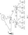
- FIG. 1 is a schematic network diagram, in accordance with some embodiments.
- a virtualization server (VS) 100 virtualizes small cells 101 , 102 , 103 , 104 and represents itself as a macro towards the nearby macros 111 , 112 , 113 , 114 while establishing X2 connectivity.
- Small cells 101 , 102 , 103 , 104 are connected to the VS via the S1 interface and to each other via the X2 interface.
- the VS aggregates or groups them and presents itself as a virtual cell on their behalf to all the nearby existing macro cells 111 , 112 , 113 , 114 , including via X2. Certain conditions need to be fulfilled for this virtualization to work, i.e.
- FIG. 2 shows a configuration showing multiple virtual cells.
- VS 100 is the gateway to the core network (MME 121 , PGW 122 , and SGW 123 ) as well as the Internet 122 for all of the virtualized small cells 101 , 102 , 103 , 104 .
- the VS is in the data path between, and acts as a gateway for, small cells 101 , 102 , 103 , 104 towards the core network.
- the VS thereby is enabled to terminate connections and tunnels, and interwork those connections and tunnels, in some cases before sending to the core network.
- Advantages of such a network topology include the following: Small cells will only have to do S1 interface. No complexity of establishing and maintaining X2 with multiple nearby macros; Macro cells will only have to do X2 with a single VS device which represents and hides all the small cells behind it; and MME is kept out of the handover signaling (due to how X2 handover between two cells works), thereby reducing load on core network.
- FIG. 1 Creating such a topology as depicted in FIG. 1 has many advantages. It simplifies the network deployment to a great extent. Simplification is the key which will enable more and more small-cell deployments worldwide. The below call flows show that handover is a solvable issue in above topology. Advantages far outweigh the minor disadvantages in certain call flows.
- FIG. 2 is a schematic network diagram showing multiple coordinating servers, in accordance with some embodiments.
- FIG. 2 shows a plurality of small cells coupled with coordinating servers (VSes) 201 and 202 , in an arrangement where small cells 211 , 212 , and 213 are virtualized by VS 201 and small cells 214 , 215 , 216 are virtualized by VS 202 .
- VS 201 and VS 202 are peers and provide virtualization of the small cells under them; the VS nodes make themselves known to the network as eNodeBs, thereby acting as virtual eNodeBs.
- X2 connection is available directly between small cell 213 and small cell 214 ; however, a connection between VS 201 and VS 202 provides handover capability, either via X2 or via another protocol. Handovers with the macro 205 are also possible with the small cells via the VS 201 (or VS 202 , link not shown) as described herein. Finally, an S1 handover is also still available via core network 220 .
- VS 201 is a virtual eNodeB and VS 202 is a virtual eNodeB, each managing up to 255 actual eNodeBs and making them part of the network as cells. This reduces neighbor relations so that up to 512 eNodeBs can be handled using a simple neighbor table of just two nodes, VS 201 and VS 202 .
- the use of multiple VS gateways enables the creation of natural geographic subsets of eNBs, instead of requiring complex coordination between multiple MMEs to split management of a large number of cells.
- FIG. 3 is a schematic network diagram showing a hierarchy of coordinating servers, in accordance with some embodiments.
- a hierarchy is in place between coordinating servers (VSes) 301 , 302 , and 303 .
- VS 301 virtualizes small cells 311 , 312 , and 313 .
- VS 302 virtualizes small cells 314 , 315 , and 316 .
- VS 301 and VS 302 relate to each other as peers and can send X2 (or other protocol) messages to each other, but do not expose each of the underlying small cells to each other as individual eNodeBs but rather as cells.
- VS 303 is hierarchically placed above VS 301 and VS 302 , and hides and virtualizes VS 301 and 302 from macro 305 and core network 320 .
- This virtualization may occur using the same method, for example, virtualizing VS 301 as a cell of VS 303 , in some embodiments. This drastically reduces signaling activity.
- further multi-level hierarchies could be used to any depth to virtualize a large number of small cells.
- small cells 311 , 312 , 313 , 314 , 315 , 316 may all be virtualized as cells at VS 303 , in some embodiments. This retains addressability of all cells in the network but continues to reduce signaling activity at each hierarchical level.
- a shared security key/token/value/secret is calculated based on shared secret information.
- the shared security key is called a KeNB.
- a first KeNB is used, and after the handover is complete, a second KeNB is used; this second KeNB is called KeNB* and is generated at both sides of the connection after the handover is complete to provide forward secrecy.
- KeNBs are derived, the parameters from which the KeNB is derived are referred to herein as precursors.
- the correct precursors are provided to enable the small cell eNB and/or the VS, in some embodiments, to calculate the KeNB and create an appropriate security context.
- Derivation of KeNB is described in 3GPP TS 33.401 Annex A.5, hereby incorporated by reference, using target PCI, EARFCN-DL, NH, or the current KeNB as appropriate according to the spec.
- the eNB shall send the NCC used for KeNB* derivation to the UE.
- an S1 handover translated to an X2 handover includes sending the X2 handover request from the VS to the target base station with the KeNB*, which is calculated based on previously stored NH, NCC pairs at the VS.
- a macro X2 handover translated to an S1 handover may include transmission of a new NH, NCC pair to the target eNB, as with a standard S1 handover.
- An S1 path switch request occurs in the standard when the target eNB has completed handover signaling with the UE, and typically results in incrementing the NCC value at the MME and computation of a new NH, i.e., by using a KASME and a locally kept NH value according to 3GPP TS 33.401 Annex A.4.
- the MME then sends the newly completed NH, NCC pair to the target eNB in an S1 path switch request acknowledge message.
- the source eNB includes AS algorithms used in the source cell (ciphering and integrity algorithms) in the source to target transparent container that shall be sent to the target eNB.
- the AS algorithms used by in the source cell are provided to the target eNB so that it can decipher and integrity verify the RRCReestablishmentComplete message.
- the UE behavior is the same in the present embodiments regardless if the handover is S1, X2 or intra-eNB and does not differ from the standard behavior.
- the UE shall derive the KeNB* from the currently active KeNB and the target PCI and its frequency EARFCN-DL using the function defined in Annex A.5.
- the UE shall first synchronize the locally kept NH parameter by computing the function defined in Annex A.4 iteratively (and increasing the NCC value until it matches the NCC value received from the source eNB via the HO command message.
- the UE shall compute the KeNB* from the synchronized NH parameter and the target PCI and its frequency EARFCN-DL using the function defined in Annex A.5.
- the UE shall use the KeNB* as the KeNB when communicating with the target eNB.
- Access Security Management Entity is the entity which receives the top-level keys in an access network from the HSS.
- ASME Access Security Management Entity
- Chaining of KeNB is derivation of a new KeNB from another KeNB (i.e., at cell handover).
- EPS AS security context are the cryptographic keys at AS level with their identifiers, the Next Hop parameter NH, the Next Hop Chaining Counter parameter NCC used for next hop access key derivation, the identifiers of the selected AS level cryptographic algorithms and counters used for replay protection. Note that the EPS AS security context only exists when cryptographically protected radio bearers are established and is otherwise void.
- K is the permanent key stored on the USIM on a UICC and in the Authentication Centre AuC.
- CK, IK is the pair of keys derived in the AuC and on the USIM during an AKA run.
- CK, IK shall be handled differently depending on whether they are used in an EPS security context or a legacy security context, as described in subclause 6.1.2.
- an intermediate key KASME shall be shared between UE and MME i.e. the ASME for EPS.
- FIG. 4 is a call flow diagram showing an initial S1 handover, in accordance with some embodiments, showing setup of X2 connectivity between the VS and macro cells.
- a small cell 401 is shown, together with VS 402 , macro 403 , and MME 404 .
- Other network nodes are not shown for clarity.
- the X2 interface can be very dynamic, i.e. setup when a neighbor relationship is known, the neighbor X2 connectivity endpoint is also discovered runtime.
- the VS implements multiple learning techniques to know the neighbor relationship between connected small cells and nearby macro. Most of the techniques need an out of band interface with the cell, e.g. SON interface or Management System Interface. Hence these are used perfectly well when the cell is also manufactured by PW, i.e. PW CWS.
- the VS learns that both are neighbors (sets up the ANR relationship).
- the VS decodes the S1-Handover-Required message coming in from Small Cell-1 and extracts the information of the cell, like PCI, EARFCN of the Small Cell-1.
- the VS then initiates X2 setup procedure towards macro.
- the macro cell's PCI, EARFCN (E-UTRA Absolute Radio Frequency Channel Number, which is related to the frequency of the macro cell), and other information could be obtained during X2 setup, or during a prior S1 handover, in some embodiments. This information can be requested without any change required to the macro from a standard protocol perspective.
- the UE's security data is obtained by the VS at the time the UE attaches to the small cell.
- FIG. 5 is a call flow diagram showing an S1-X2 handover, in accordance with some embodiments, showing a handover from LTE small cell towards macro using X2 link at the VS.
- Small cell 2 501 is shown, together with VS 502 , macro cell 503 , and MME 504 .
- Other network nodes are not shown for clarity.
- the VS now has X2 link available between the VS and the macro cell.
- the following call flow shows how a handover from small cell-2 or we can say any small cell towards Macro Cell-1 is going to use the X2 link.
- the VS To initiate X2 Handover Request towards Macro-Cell-1, the VS has to calculate the UE's security key to be used on access stratum between the Macro-Cell-1 and the UE.
- the VS When the UE came in to small-cell-1, the VS stored the ‘Kenb’ value as given out by MME to the Small Cell-1 for this UE.
- the VS uses this value to compute the ‘Kenb*’ value as needed by target Macro Cell-1.
- the VS knows the target PCI, target EARFCN-DL value of Macro-Cell-1 (since it has done X2 Setup procedure with Macro Cell-1). It uses these to calculate ‘Kenb*’.
- FIG. 6 is a call flow diagram showing an X2-S1 handover, in accordance with some embodiments, showing a handover from macro cell to LTE small cell using X2 link at the VS.
- a small cell 601 is shown, together with VS 602 , macro 603 , and MME 604 .
- Other network nodes are not shown for clarity.
- the X2 link is also used when handover is initiated by macro cell.
- the VS has to originate S1-Handover-Request towards Small Cell-1 when it receives X2 Handover-Request from Macro-Cell-1.
- the VS has to include security information for UE to be used on access stratum.
- Security information consists of ‘Next Hop Chaining Count (NCC)’, and ‘Next Hop key (NH)’.
- Small Cell-1 Upon receiving this message, Small Cell-1 would derive ‘Kenb*’. Here it would use its own PCI and DL EARFCN parameters to arrive at the result.
- VS would go to MME with S1 Path Switch Request, as further described in 3GPP TS 33.401.
- NCC Next Hop Chaining Count
- NH Next Hop key
- VS will itself calculate the Kenb* value that is in use for this UE at Small Cell-1 and store it in its data. This value can be used for future handovers.
- security keys are routinely advanced within the same eNB without handover.
- we perform this process to obtain the precursors for a new key at a gateway in the data path, and the new key is used for the handover.
- Downlink Path switch towards MME happens before the handover actually completes. This means that downlink data will start coming at VS before the UE has moved to the small cell. VS may either buffer the data or drop the data packets, in some embodiments.
- X2 Handover Request is received by VS from a macro ENB.
- Macro ENB has computed the target key by itself.
- VS usually goes for S1 HO towards the target (connected over S1). But here VS can directly go to MME with Path-Switch-Request. As if the UE has moved.
- Target ENB will compute the key and also copy back the NCC value in the target-to-source container that we will relay towards the macro ENB over X2.
- the Macro-ENB will issue command to the UE to move (with the NCC value taken from the container).
- One aspect to consider is to implement intermediate buffers outside of PDCP layer where GTP-u packets are held until X2 data forwarding completes from the original Macro->VS handover before sending them to eNB. This reduces loss of data to the extent that it was pending in the macro's buffers.
- source macro is in Handover-Preparation-Wait state. It will be in this state until it receives X2-Handover-Request-Ack which will be sent by the VS (upon receiving S1 Handover Ack).
- the VS has already become the anchor for this UE towards the EPC, whether handover succeeds or fails, the VS has to send X2-UE-Context-Release to the source macro. This it should do after a wait for S1-Handover-Notify from target or a timer expiry.
- FIG. 7 is a schematic diagram of an enhanced base station, in accordance with some embodiments.
- Mesh network base station 700 may include processor 702 , processor memory 704 in communication with the processor, baseband processor 706 , and baseband processor memory 708 in communication with the baseband processor.
- Base station 700 may also include first radio transceiver 710 and second radio transceiver 712 , internal universal serial bus (USB) port 716 , and subscriber information module card (SIM card) 718 coupled to USB port 714 .
- the second radio transceiver 712 itself may be coupled to USB port 716 , and communications from the baseband processor may be passed through USB port 716 .
- a virtualization layer 730 may also be included for mediating communications with an evolved packet core EPC, specifically including the core network EPC (not shown) and local evolved packet core (EPC) module 720 .
- EPC evolved packet core
- Local EPC 720 may be used for authenticating users and performing other EPC-dependent functions when no backhaul link is available.
- Local EPC 720 may include local HSS 722 , local MME 724 , local SGW 726 , and local PGW 728 , as well as other modules.
- Local EPC 720 may incorporate these modules as software modules, processes, or containers.
- Local EPC 720 may alternatively incorporate these modules as a small number of monolithic software processes.
- Virtualization layer 730 and local EPC 720 may each run on processor 702 or on another processor, or may be located within another device.
- Processor 702 and baseband processor 706 are in communication with one another.
- Processor 702 may perform routing functions, and may determine if/when a switch in network configuration is needed.
- Baseband processor 706 may generate and receive radio signals for both radio transceivers 710 and 712 , based on instructions from processor 702 .
- processors 702 and 706 may be on the same physical logic board. In other embodiments, they may be on separate logic boards.
- the first radio transceiver 710 may be a radio transceiver capable of providing LTE eNodeB functionality, and may be capable of higher power and multi-channel OFDMA.
- the second radio transceiver 712 may be a radio transceiver capable of providing LTE UE functionality. Both transceivers 710 and 712 are capable of receiving and transmitting on one or more LTE bands. In some embodiments, either or both of transceivers 710 and 712 may be capable of providing both LTE eNodeB and LTE UE functionality.
- Transceiver 710 may be coupled to processor 702 via a Peripheral Component Interconnect-Express (PCI-E) bus, and/or via a daughtercard.
- PCI-E Peripheral Component Interconnect-Express
- transceiver 712 As transceiver 712 is for providing LTE UE functionality, in effect emulating a user equipment, it may be connected via the same or different PCI-E bus, or by a
- SIM card 718 may provide information required for authenticating the simulated UE to the evolved packet core (EPC). When no access to an operator EPC is available, local EPC 720 may be used, or another local EPC on the network may be used. This information may be stored within the SIM card, and may include one or more of an international mobile equipment identity (IMEI), international mobile subscriber identity (IMSI), or other parameter needed to identify a UE. Special parameters may also be stored in the SIM card or provided by the processor during processing to identify to a target eNodeB that device 700 is not an ordinary UE but instead is a special UE for providing backhaul to device 700 .
- IMEI international mobile equipment identity
- IMSI international mobile subscriber identity
- Special parameters may also be stored in the SIM card or provided by the processor during processing to identify to a target eNodeB that device 700 is not an ordinary UE but instead is a special UE for providing backhaul to device 700 .
- Wired backhaul or wireless backhaul may be used.
- Wired backhaul may be an Ethernet-based backhaul (including Gigabit Ethernet), or a fiber-optic backhaul connection, or a cable-based backhaul connection, in some embodiments.
- wireless backhaul may be provided in addition to wireless transceivers 710 and 712 , which may be Wi-Fi 802.11a/b/g/n/ac/ad/ah, Bluetooth, ZigBee, microwave (including line-of-sight microwave), or another wireless backhaul connection. Any of the wired and wireless connections may be used for either access or backhaul, according to identified network conditions and needs, and may be under the control of processor 702 for reconfiguration.
- a home eNodeB may also be included, such as a home eNodeB, a local gateway (LGW), a self-organizing network (SON) module, or another module. Additional radio amplifiers, radio transceivers and/or wired network connections may also be included.
- LGW local gateway
- SON self-organizing network
- Processor 702 may identify the appropriate network configuration, and may perform routing of packets from one network interface to another accordingly.
- Processor 702 may use memory 704 , in particular to store a routing table to be used for routing packets.
- Baseband processor 706 may perform operations to generate the radio frequency signals for transmission or retransmission by both transceivers 710 and 712 .
- Baseband processor 706 may also perform operations to decode signals received by transceivers 710 and 712 .
- Baseband processor 706 may use memory 708 to perform these tasks.
- FIG. 8 is a schematic diagram of a virtualization server in a Long Term Evolution (LTE) architecture, in accordance with some embodiments.
- Virtualization server 801 provides services to, and is coupled to, eNodeB 1 802 and eNodeB 8 803 , on a RAN side of a network (i.e., inside of the gateway).
- Virtualization server 801 provides services to, and is coupled to, MME 804 , macro eNodeB 805 , and macro eNodeB 806 , on a core network side of the network (outside of the gateway).
- Virtualization server 801 corresponds to LAC 110 , in some embodiments.
- SON self-organizing network
- NRT neighbor relation table
- EPC evolved packet core
- RAN radio access network
- UE user equipment
- S1/X2 handover mapping table 843 Each of modules 811 , 821 , 831 , and 841 are coupled to each other within virtualization server 801 , and may execute on one or more shared processors (not shown) coupled with memory (not shown).
- SON module 811 may perform NRT maintenance, load information processing and fractional frequency reuse (FFR) processing; RAN module 831 may perform X2 association management with eNodeBs 802 , 803 ; EPC module 821 may perform X2 association management with macro eNodeBs 805 , 806 ; and UE module may perform X2 handover and S1/X2 translation between eNodeBs 802 , 803 and macro eNodeBs 805 , 806 . All the above managers/modules interact with each other to accomplish the assigned functionality.
- FFR fractional frequency reuse
- EPC module 821 may contain EPC finite state machine module 822 and macro eNodeB table 823 .
- EPC finite state machine module 822 may track the state of any messages or call flows being sent or received with a macro eNodeB, such as macro eNodeBs 805 , 806 .
- EPC FSM module 822 may, for example, determine whether a handover has been initiated by macro eNodeB 805 , 806 , as well as other functions.
- EPC FSM module 822 may also track which eNodeBs within the network are involved in communicating with the macro eNodeBs, and may perform network address translation by mapping incoming requests and messages from an eNodeB address external to the gateway 801 to an address internal to the gateway 801 , using eNodeB table 823 . In some embodiments the tracking and network address translation functions may be performed at the RAN module or in another module. Macro eNodeB table 823 may track all macro eNodeBs and any connections, bearers, tunnels, or calls open between an eNodeB internal to the gateway, such as eNodeBs 802 and 803 .
- RAN module 831 may contain RAN finite state machine module 832 and eNodeB table 834 .
- RAN module 831 is the counterpart to EPC module 821 on the side of the network inside the gateway.
- RAN FSM module 832 may track and receive messages and requests, and may track the state of the RAN node in any message exchange.
- eNodeB table 834 may include a mapping to from an eNodeB ID or cell ID to the ECGI ID used outside of the private network.
- RAN module 831 may use eNodeB table 834 to perform network address translation, if applicable, on messages received by RAN module from eNodeBs 802 , 803 , so that the messages can be sent upstream to the EPC and/or core network.
- network address translation is used at both RAN module 831 and EPC module 821 , for connections initiated at the RAN and at the EPC, respectively.
- RAN module 831 may determine that an X2 connection may be terminated locally, without being sent outside the gateway, or even without being sent to the gateway at all. In those cases, RAN module 831 can instruct eNodeBs 802 , 803 to perform direct X2 communication.
- RAN module 831 may perform proxying and network address translation for the S1 connection, in addition to supporting the X2 connection, in some embodiments.
- RAN module 831 may also pass along any UE measurement reports received from UEs to either or both of UE module 841 and SON module 811 .
- UE module 841 may contain UE finite state machine module 842 and S1/X2 handover mapping table 843 .
- UE finite state machine module 842 may track states for call flows that are in process between a UE connected to one or more eNodeBs and either a core network node or a target eNodeB.
- UE FSFM 842 may track when an X2 handover request message has not been responded to and should expire.
- UE FSFM 842 may also track X2/S1 handovers, in conjunction with S1/X2 handover mapping table 843 .
- UE FSFM 842 may, in some embodiments, determine whether a handover should be translated from S1 to X2, or vice versa, before the handover should continue.
- UE module 841 handles UE-related requests from both the RAN module 831 (from nodes internal to gateway 801 ) and from EPC module 821 (from nodes external to gateway 801 ).
- eNodeB or “eNodeB” are used to refer to an LTE cellular base station.
- HeNodeBs home eNodeBs
- the words “federated,” “virtualized,” “proxy” or “proxied” may be viewed as aspects of the same concept.
- the federated X2 gateway provides X2 virtualization, in that it federates X2 messages from a plurality of eNodeBs and virtualizes the plurality of eNodeBs to provide a single virtualized eNodeB.
- the X2 gateway provides this federation or virtualization at least in part by providing proxy functionality, such that X2 messages from each of the plurality of eNodeBs may be proxied by the X2 gateway to and from an EPC or core network node.
- proxy functionality such that X2 messages from each of the plurality of eNodeBs may be proxied by the X2 gateway to and from an EPC or core network node.
- the X2 gateway could be part of an LTE access controller or core network node, part of an eNodeB, co-located with another device, or on its own independent
- small cell While the present disclosure uses the term “small cell,” this term is used merely to illustrate the concepts herein, and nothing is implied regarding size, power level etc. for any cells that could be used with the disclosed systems and methods, i.e. “small cell” may be interpreted as including macro cells, femto cells, multi-radio access technology (RAT) access nodes, indoor cells, outdoor cells, etc.
- RAT multi-radio access technology
- all of the described functions may be performed at an eNodeB, or at a multi-radio access technology node (multi-RAT) node, instead of at a virtualization server, which would provide many of the described benefits herein.
- the functions of the virtualization server may be broken up and spread across multiple network nodes, or multiple software or hardware modules within the same network node, and may be physically located in a single location, or multiple locations.
- the network node may be in the data path located between the radio access network (RAN) and the core network, in some embodiments, or may be located at another location in the network.
- RAN radio access network
- a high-bandwidth wired connection may be used for backhaul, such as coaxial cable, fiber optic cable, or Ethernet, or a reduced-bandwidth wireless connection, such as microwave, line-of-sight, or other physical connections may be used as backhaul.
- the protocols described herein may be optimized for greater or lesser latency, for more or fewer mesh nodes, for more or fewer data streams, and other alternatives. In some embodiments, these optimizations may be performed at the eNodeB, at the virtualization server, within a function performing radio resource allocation and coding selection, or at another location. In some embodiments, a virtualization server may identify and initiate power adjustments to improve channel quality.
- the mesh network nodes may provide complete or partial guesses at what paths are the optimal or best paths during a particular time interval, and may be enabled to send messages back to the virtualization server to communicate these complete or partial guesses.
- the base stations described herein may be compatible with a Long Term Evolution (LTE) radio transmission protocol or air interface.
- LTE-compatible base stations may be eNodeBs.
- the base stations may also support other air interfaces, such as UMTS/HSPA, CDMA/CDMA2000, GSM/EDGE, GPRS, EVDO, other 3G/2G, legacy TDD, or other air interfaces used for mobile telephony.
- the base stations described herein may support Wi-Fi air interfaces, which may include one of 802.11a/b/g/n/ac/ad/af/ah.
- the base stations described herein may support 802.16 (WiMAX), or other air interfaces. In some embodiments, the base stations described herein may provide access to land mobile radio (LMR)-associated radio frequency bands. In some embodiments, the base stations described herein may also support more than one of the above radio frequency protocols, and may also support transmit power adjustments for some or all of the radio frequency protocols supported.
- WiMAX WiMAX
- LMR land mobile radio
- a computer-readable medium such as a computer memory storage device, a hard disk, a flash drive, an optical disc, or the like.
- a computer-readable medium such as a computer memory storage device, a hard disk, a flash drive, an optical disc, or the like.
- wireless network topology can also apply to wired networks, optical networks, and the like.
- the methods may apply to LTE-compatible networks, to UMTS-compatible networks, or to networks for additional protocols that utilize radio frequency data transmission.
Landscapes
- Engineering & Computer Science (AREA)
- Computer Networks & Wireless Communication (AREA)
- Signal Processing (AREA)
- Computer Security & Cryptography (AREA)
- Mobile Radio Communication Systems (AREA)
Abstract
Description
Claims (13)
Priority Applications (1)
| Application Number | Priority Date | Filing Date | Title |
|---|---|---|---|
| US15/721,728 US11026136B2 (en) | 2014-03-07 | 2017-09-29 | Handovers with simplified network topology |
Applications Claiming Priority (5)
| Application Number | Priority Date | Filing Date | Title |
|---|---|---|---|
| US201461949455P | 2014-03-07 | 2014-03-07 | |
| US201461976146P | 2014-04-07 | 2014-04-07 | |
| US14/642,544 US10595242B2 (en) | 2014-03-07 | 2015-03-09 | Federated X2 gateway |
| US201662401695P | 2016-09-29 | 2016-09-29 | |
| US15/721,728 US11026136B2 (en) | 2014-03-07 | 2017-09-29 | Handovers with simplified network topology |
Related Parent Applications (1)
| Application Number | Title | Priority Date | Filing Date |
|---|---|---|---|
| US14/642,544 Continuation-In-Part US10595242B2 (en) | 2014-03-07 | 2015-03-09 | Federated X2 gateway |
Publications (2)
| Publication Number | Publication Date |
|---|---|
| US20180041927A1 US20180041927A1 (en) | 2018-02-08 |
| US11026136B2 true US11026136B2 (en) | 2021-06-01 |
Family
ID=61069700
Family Applications (1)
| Application Number | Title | Priority Date | Filing Date |
|---|---|---|---|
| US15/721,728 Active US11026136B2 (en) | 2014-03-07 | 2017-09-29 | Handovers with simplified network topology |
Country Status (1)
| Country | Link |
|---|---|
| US (1) | US11026136B2 (en) |
Cited By (1)
| Publication number | Priority date | Publication date | Assignee | Title |
|---|---|---|---|---|
| US20220232655A1 (en) * | 2021-01-11 | 2022-07-21 | Electronics And Telecommunications Research Institute | Method and apparatus for dual connectivity management in wireless communication system |
Families Citing this family (12)
| Publication number | Priority date | Publication date | Assignee | Title |
|---|---|---|---|---|
| CN106165527A (en) * | 2014-04-14 | 2016-11-23 | 日本电气株式会社 | Communication device, communication method and storage medium |
| WO2016163032A1 (en) * | 2015-04-10 | 2016-10-13 | 富士通株式会社 | Wireless communication system, base station, mobile station, and processing method |
| KR102531563B1 (en) | 2017-01-06 | 2023-05-12 | 패러렐 와이어리스, 인크. | X2 arbitration through aggregation optimization |
| US11240879B2 (en) | 2017-01-06 | 2022-02-01 | Parallel Wireless, Inc. | X2 brokering with aggregation optimization |
| CN109863731B (en) * | 2017-08-03 | 2020-11-10 | 华为技术有限公司 | Data transmission method, related equipment and communication system |
| EP3678449B1 (en) * | 2017-09-21 | 2022-06-01 | Huawei Technologies Co., Ltd. | Connection management method and user equipment |
| US11923924B2 (en) * | 2018-02-26 | 2024-03-05 | Parallel Wireless, Inc. | Miniature antenna array with polar combining architecture |
| US10568005B2 (en) * | 2018-03-20 | 2020-02-18 | Wipro Limited | Method and system for X2-messaging in cloud radio access network (C-RAN) |
| US20220132381A1 (en) * | 2020-10-23 | 2022-04-28 | At&T Intellectual Property I, L.P. | User plane adaptation for mobile integrated access and backhaul |
| US12245203B2 (en) | 2020-10-23 | 2025-03-04 | At&T Intellectual Property I, L.P. | Resource coordination including for full-duplex integrated access and backhaul |
| US11737002B2 (en) * | 2021-07-28 | 2023-08-22 | Hewlett Packard Enterprise Development Lp | Selective caching of pairwise master keys in streamlined roaming |
| WO2025014185A1 (en) * | 2023-07-12 | 2025-01-16 | Samsung Electronics Co., Ltd. | Methods for handling authentication during lower layers triggered mobility (ltm) in wireless network |
Citations (34)
| Publication number | Priority date | Publication date | Assignee | Title |
|---|---|---|---|---|
| US20120051275A1 (en) * | 2010-08-31 | 2012-03-01 | Cisco Technology, Inc. | Reducing latency and packet loss related to handoffs of mobile video traffic |
| US20120163336A1 (en) * | 2010-06-18 | 2012-06-28 | Interdigital Patent Holdings, Inc. | Distributed architecture for security keys derivation in support of non-involved core network handover |
| US20120220290A1 (en) | 2008-03-31 | 2012-08-30 | At&T Mobility Ii Llc | Potential call drop indicator |
| US20120263096A1 (en) * | 2010-06-18 | 2012-10-18 | Telefonaktiebolaget L M Ericsson (Publ) | Methods and nodes for probing types of interfaces |
| US20120307795A1 (en) | 2009-12-04 | 2012-12-06 | Ntt Docomo, Inc. | Mobile communication method and gateway device |
| US20120315956A1 (en) | 2010-03-23 | 2012-12-13 | Sumitomo Electric Industries, Ltd. | Base station device, terminal device, receiver-side base station device, and wireless communication method |
| CN102958197A (en) | 2012-11-19 | 2013-03-06 | 华为技术有限公司 | Method for establishing X2 service signaling connection, base station and CSG (cell site gateway) |
| US20130077482A1 (en) | 2011-09-20 | 2013-03-28 | Accelera Mobile Broadband, Inc. | Seamless handoff, offload, and load balancing in integrated wi-fi/small cell systems |
| US20130136074A1 (en) | 2010-04-06 | 2013-05-30 | Kyocera Corporation | Radio communication system, radio base station, and communication control method |
| WO2013107346A1 (en) | 2012-01-18 | 2013-07-25 | 中兴通讯股份有限公司 | Method and device for establishing interface connection between base stations |
| US8644831B2 (en) | 2009-01-22 | 2014-02-04 | Samsung Electronics Co., Ltd | Redirection method of femto cell and communication system based thereon |
| US20140079026A1 (en) | 2011-05-12 | 2014-03-20 | Telefonaktiebolaget L M Ericsson (Publ) | Methods in base stations, base stations, computer programs and computer program products |
| US20140204765A1 (en) | 2011-09-26 | 2014-07-24 | Huawei Technologies Co., Ltd. | Interference control method and device |
| US20140233386A1 (en) | 2013-02-18 | 2014-08-21 | Samsung Electronics Co., Ltd. | Method and system for offloading handover of wireless connections from a lte network to a wi-fi network |
| US20140308959A1 (en) | 2013-04-15 | 2014-10-16 | Nokia Siemens Networks Oy | Methods and Apparatus for Handover Management |
| EP2816846A1 (en) | 2013-06-17 | 2014-12-24 | Alcatel Lucent | 3GPP base station, in particular eNodeB, enabling discovery of non-3GPP access networks, in particular Wi-Fi access points |
| US20150146519A1 (en) * | 2013-11-22 | 2015-05-28 | General Dynamics Broadband Inc. | Apparatus and Methods for Supporting Control Plane Data |
| US20150215774A1 (en) * | 2012-08-09 | 2015-07-30 | Zte Corporation | Method and Device for Processing and Managing an Establishment of X2 Connection |
| US20150257051A1 (en) | 2014-03-07 | 2015-09-10 | Parallel Wireless, Inc. | Federated X2 Gateway |
| US9226204B2 (en) | 2008-10-29 | 2015-12-29 | Lenovo Group Limited | Cell type information sharing between neighbor base stations |
| WO2015199241A1 (en) | 2014-06-23 | 2015-12-30 | Nec Corporation | Communication system adapted for key derivation during handover |
| US20160014650A1 (en) | 2014-07-11 | 2016-01-14 | Luminate Wireless, Inc. | Handover methods and apparatus |
| US20160105919A1 (en) | 2013-06-04 | 2016-04-14 | Nec Corporation | Communications system |
| US20160119941A1 (en) | 2013-06-03 | 2016-04-28 | Lg Electronics Inc. | Method for managing wireless resource and apparatus therefor |
| US20160119847A1 (en) * | 2013-05-10 | 2016-04-28 | Lg Electronics Inc. | Method and Apparatus for Transmitting Information on User Equipments According to Type in Wireless Communication System |
| US20160142944A1 (en) | 2014-11-14 | 2016-05-19 | Parallel Wireless, Inc. | Seamless Mobile Handover |
| US20160165499A1 (en) | 2013-07-05 | 2016-06-09 | Lg Electronics Inc. | Method and apparatus for forwarding data for small cell in wireless communication system |
| US20160165438A1 (en) | 2013-07-25 | 2016-06-09 | Samsung Electronics Co., Ltd. | Method for resolving security issues using nh and ncc pairs in mobile communication system |
| US20160183137A1 (en) | 2013-08-09 | 2016-06-23 | Kyocera Corporation | Base station |
| US20160227449A1 (en) | 2013-09-27 | 2016-08-04 | Nec Corporation | Communication system |
| WO2016141964A1 (en) | 2015-03-09 | 2016-09-15 | Nokia Solutions And Networks Oy | Dynamic setup of secure communication |
| US20170070923A1 (en) | 2014-02-21 | 2017-03-09 | Convida Wireless, Llc | Handover in integrated small cell and wifi networks |
| US20170156086A1 (en) | 2014-07-14 | 2017-06-01 | Convida Wireless, Llc | Inter-system handover and multi-connectivity via an integrated small cell and wifi gateway |
| US9742535B2 (en) | 2013-12-23 | 2017-08-22 | Telefonica, S.A. | Method and a system for performing virtualization of a radio access technology over orthogonal frequency-division multiple access (OFDMA) wireless networks and computer program products thereof |
-
2017
- 2017-09-29 US US15/721,728 patent/US11026136B2/en active Active
Patent Citations (35)
| Publication number | Priority date | Publication date | Assignee | Title |
|---|---|---|---|---|
| US20120220290A1 (en) | 2008-03-31 | 2012-08-30 | At&T Mobility Ii Llc | Potential call drop indicator |
| US9226204B2 (en) | 2008-10-29 | 2015-12-29 | Lenovo Group Limited | Cell type information sharing between neighbor base stations |
| US8644831B2 (en) | 2009-01-22 | 2014-02-04 | Samsung Electronics Co., Ltd | Redirection method of femto cell and communication system based thereon |
| US20120307795A1 (en) | 2009-12-04 | 2012-12-06 | Ntt Docomo, Inc. | Mobile communication method and gateway device |
| US20120315956A1 (en) | 2010-03-23 | 2012-12-13 | Sumitomo Electric Industries, Ltd. | Base station device, terminal device, receiver-side base station device, and wireless communication method |
| US20130136074A1 (en) | 2010-04-06 | 2013-05-30 | Kyocera Corporation | Radio communication system, radio base station, and communication control method |
| US20120263096A1 (en) * | 2010-06-18 | 2012-10-18 | Telefonaktiebolaget L M Ericsson (Publ) | Methods and nodes for probing types of interfaces |
| US20120163336A1 (en) * | 2010-06-18 | 2012-06-28 | Interdigital Patent Holdings, Inc. | Distributed architecture for security keys derivation in support of non-involved core network handover |
| US20120051275A1 (en) * | 2010-08-31 | 2012-03-01 | Cisco Technology, Inc. | Reducing latency and packet loss related to handoffs of mobile video traffic |
| US20140079026A1 (en) | 2011-05-12 | 2014-03-20 | Telefonaktiebolaget L M Ericsson (Publ) | Methods in base stations, base stations, computer programs and computer program products |
| US20130077482A1 (en) | 2011-09-20 | 2013-03-28 | Accelera Mobile Broadband, Inc. | Seamless handoff, offload, and load balancing in integrated wi-fi/small cell systems |
| US9510256B2 (en) | 2011-09-20 | 2016-11-29 | Wildfire.Exchange, Inc. | Seamless handoff, offload, and load balancing in integrated Wi-Fi/small cell systems |
| US20140204765A1 (en) | 2011-09-26 | 2014-07-24 | Huawei Technologies Co., Ltd. | Interference control method and device |
| WO2013107346A1 (en) | 2012-01-18 | 2013-07-25 | 中兴通讯股份有限公司 | Method and device for establishing interface connection between base stations |
| US20150215774A1 (en) * | 2012-08-09 | 2015-07-30 | Zte Corporation | Method and Device for Processing and Managing an Establishment of X2 Connection |
| CN102958197A (en) | 2012-11-19 | 2013-03-06 | 华为技术有限公司 | Method for establishing X2 service signaling connection, base station and CSG (cell site gateway) |
| US20140233386A1 (en) | 2013-02-18 | 2014-08-21 | Samsung Electronics Co., Ltd. | Method and system for offloading handover of wireless connections from a lte network to a wi-fi network |
| US20140308959A1 (en) | 2013-04-15 | 2014-10-16 | Nokia Siemens Networks Oy | Methods and Apparatus for Handover Management |
| US20160119847A1 (en) * | 2013-05-10 | 2016-04-28 | Lg Electronics Inc. | Method and Apparatus for Transmitting Information on User Equipments According to Type in Wireless Communication System |
| US20160119941A1 (en) | 2013-06-03 | 2016-04-28 | Lg Electronics Inc. | Method for managing wireless resource and apparatus therefor |
| US20160105919A1 (en) | 2013-06-04 | 2016-04-14 | Nec Corporation | Communications system |
| EP2816846A1 (en) | 2013-06-17 | 2014-12-24 | Alcatel Lucent | 3GPP base station, in particular eNodeB, enabling discovery of non-3GPP access networks, in particular Wi-Fi access points |
| US20160165499A1 (en) | 2013-07-05 | 2016-06-09 | Lg Electronics Inc. | Method and apparatus for forwarding data for small cell in wireless communication system |
| US20160165438A1 (en) | 2013-07-25 | 2016-06-09 | Samsung Electronics Co., Ltd. | Method for resolving security issues using nh and ncc pairs in mobile communication system |
| US20160183137A1 (en) | 2013-08-09 | 2016-06-23 | Kyocera Corporation | Base station |
| US20160227449A1 (en) | 2013-09-27 | 2016-08-04 | Nec Corporation | Communication system |
| US20150146519A1 (en) * | 2013-11-22 | 2015-05-28 | General Dynamics Broadband Inc. | Apparatus and Methods for Supporting Control Plane Data |
| US9742535B2 (en) | 2013-12-23 | 2017-08-22 | Telefonica, S.A. | Method and a system for performing virtualization of a radio access technology over orthogonal frequency-division multiple access (OFDMA) wireless networks and computer program products thereof |
| US20170070923A1 (en) | 2014-02-21 | 2017-03-09 | Convida Wireless, Llc | Handover in integrated small cell and wifi networks |
| US20150257051A1 (en) | 2014-03-07 | 2015-09-10 | Parallel Wireless, Inc. | Federated X2 Gateway |
| WO2015199241A1 (en) | 2014-06-23 | 2015-12-30 | Nec Corporation | Communication system adapted for key derivation during handover |
| US20160014650A1 (en) | 2014-07-11 | 2016-01-14 | Luminate Wireless, Inc. | Handover methods and apparatus |
| US20170156086A1 (en) | 2014-07-14 | 2017-06-01 | Convida Wireless, Llc | Inter-system handover and multi-connectivity via an integrated small cell and wifi gateway |
| US20160142944A1 (en) | 2014-11-14 | 2016-05-19 | Parallel Wireless, Inc. | Seamless Mobile Handover |
| WO2016141964A1 (en) | 2015-03-09 | 2016-09-15 | Nokia Solutions And Networks Oy | Dynamic setup of secure communication |
Non-Patent Citations (5)
| Title |
|---|
| Local Gateway Assisted Handover Key Derivation in Enterprise Femtocell Network, Scientific Research Publishing, Apr. 2015. * |
| PCT International Search Report for PCT/US17/54639, received Jan. 19, 2018. |
| PCT International Search Report for PCT/US18/12852, received Mar. 9, 2018. |
| Peng Wang, Xiaojuan Zhang, "Local Gateway Assisted Handover Key Derivation in Enterprise Femtocell Network," Int. J. Communications, Network and System Sciences, 2015, 70-78. |
| Third Generation Partnership Project, "3rd Generation Partnership Project; Technical Specification Group Services and System Aspects; 3GPP System Architecture Evolution (SAE); Security Architecture (Release 9)," 3GPP TS 33.401 V9.8.0 (Oct. 2015). |
Cited By (2)
| Publication number | Priority date | Publication date | Assignee | Title |
|---|---|---|---|---|
| US20220232655A1 (en) * | 2021-01-11 | 2022-07-21 | Electronics And Telecommunications Research Institute | Method and apparatus for dual connectivity management in wireless communication system |
| US12289781B2 (en) * | 2021-01-11 | 2025-04-29 | Electronics And Telecommunications Research Institute | Method and apparatus for dual connectivity management in wireless communication system |
Also Published As
| Publication number | Publication date |
|---|---|
| US20180041927A1 (en) | 2018-02-08 |
Similar Documents
| Publication | Publication Date | Title |
|---|---|---|
| US11026136B2 (en) | Handovers with simplified network topology | |
| US11050727B2 (en) | Security key generation and management method of PDCP distributed structure for supporting dual connectivity | |
| CN109661829B (en) | Techniques for handing off a connection between a wireless device and a local area network from a source access node to a target access node | |
| EP3474584B1 (en) | Method and apparatus to enable multiple wireless connections | |
| US9510387B2 (en) | Recovering connection in LTE local area network for EPS and local services | |
| US20150029973A1 (en) | Signalling Interfaces in Communications | |
| US11665597B2 (en) | UE mobility across super-cells | |
| CN108370508B (en) | A node for use in a communication network and method of operating the same | |
| WO2015161575A1 (en) | Method, base station, mobile management entity, and system for reporting location of user terminal | |
| US20160150577A1 (en) | Lte based wireless backhaul connection to cellular network base station | |
| EP3520316B1 (en) | Handovers with simplified network topology | |
| US10412056B2 (en) | Ultra dense network security architecture method | |
| US9572158B2 (en) | Residential local break out in a communication system | |
| WO2022055402A1 (en) | Source and target network nodes and methods therein for preventing agents from illegitimately identifying the source network node when resuming a wireless terminal in a target network node in a wireless communications network |
Legal Events
| Date | Code | Title | Description |
|---|---|---|---|
| FEPP | Fee payment procedure |
Free format text: ENTITY STATUS SET TO UNDISCOUNTED (ORIGINAL EVENT CODE: BIG.); ENTITY STATUS OF PATENT OWNER: SMALL ENTITY |
|
| FEPP | Fee payment procedure |
Free format text: ENTITY STATUS SET TO SMALL (ORIGINAL EVENT CODE: SMAL); ENTITY STATUS OF PATENT OWNER: SMALL ENTITY |
|
| AS | Assignment |
Owner name: VENTURE LENDING & LEASING VIII, INC., CALIFORNIA Free format text: SECURITY INTEREST;ASSIGNOR:PARALLEL WIRELESS, INC.;REEL/FRAME:045865/0111 Effective date: 20180404 Owner name: VENTURE LENDING & LEASING VII, INC., CALIFORNIA Free format text: SECURITY INTEREST;ASSIGNOR:PARALLEL WIRELESS, INC.;REEL/FRAME:045865/0111 Effective date: 20180404 |
|
| STPP | Information on status: patent application and granting procedure in general |
Free format text: RESPONSE TO NON-FINAL OFFICE ACTION ENTERED AND FORWARDED TO EXAMINER |
|
| STPP | Information on status: patent application and granting procedure in general |
Free format text: FINAL REJECTION MAILED |
|
| STPP | Information on status: patent application and granting procedure in general |
Free format text: DOCKETED NEW CASE - READY FOR EXAMINATION |
|
| STPP | Information on status: patent application and granting procedure in general |
Free format text: NON FINAL ACTION MAILED |
|
| AS | Assignment |
Owner name: VENTURE LENDING & LEASING VIII, INC., CALIFORNIA Free format text: SECURITY INTEREST;ASSIGNOR:PARALLEL WIRELESS, INC.;REEL/FRAME:051459/0959 Effective date: 20191220 Owner name: VENTURE LENDING & LEASING IX, INC., CALIFORNIA Free format text: SECURITY INTEREST;ASSIGNOR:PARALLEL WIRELESS, INC.;REEL/FRAME:051459/0959 Effective date: 20191220 |
|
| STPP | Information on status: patent application and granting procedure in general |
Free format text: RESPONSE TO NON-FINAL OFFICE ACTION ENTERED AND FORWARDED TO EXAMINER |
|
| STPP | Information on status: patent application and granting procedure in general |
Free format text: NOTICE OF ALLOWANCE MAILED -- APPLICATION RECEIVED IN OFFICE OF PUBLICATIONS |
|
| AS | Assignment |
Owner name: PARALLEL WIRELESS, INC., NEW HAMPSHIRE Free format text: ASSIGNMENT OF ASSIGNORS INTEREST;ASSIGNORS:RAVAL, KARTIK SHASHIKANT;NANOTI, SOURABH;RAO, PRASHANTH;AND OTHERS;SIGNING DATES FROM 20170928 TO 20170929;REEL/FRAME:055895/0947 |
|
| AS | Assignment |
Owner name: PARALLEL WIRELESS, INC., NEW HAMPSHIRE Free format text: ASSIGNMENT OF ASSIGNORS INTEREST;ASSIGNORS:RAVAL, KARTIK SHASHIKANT;RAO, PRASHANTH;GOYAL, ANUPAM;SIGNING DATES FROM 20150818 TO 20150910;REEL/FRAME:056074/0291 |
|
| STPP | Information on status: patent application and granting procedure in general |
Free format text: PUBLICATIONS -- ISSUE FEE PAYMENT RECEIVED |
|
| STPP | Information on status: patent application and granting procedure in general |
Free format text: PUBLICATIONS -- ISSUE FEE PAYMENT VERIFIED |
|
| STCF | Information on status: patent grant |
Free format text: PATENTED CASE |
|
| AS | Assignment |
Owner name: WTI FUND X, INC., CALIFORNIA Free format text: SECURITY INTEREST;ASSIGNOR:PARALLEL WIRELESS, INC.;REEL/FRAME:059279/0851 Effective date: 20220225 Owner name: VENTURE LENDING & LEASING IX, INC., CALIFORNIA Free format text: SECURITY INTEREST;ASSIGNOR:PARALLEL WIRELESS, INC.;REEL/FRAME:059279/0851 Effective date: 20220225 |
|
| AS | Assignment |
Owner name: PARALLEL WIRELESS, INC., NEW HAMPSHIRE Free format text: RELEASE BY SECURED PARTY;ASSIGNORS:VENTURE LENDING & LEASING VII, INC.;VENTURE LENDING & LEASING VIII, INC.;REEL/FRAME:060562/0569 Effective date: 20220629 Owner name: PARALLEL WIRELESS, INC., NEW HAMPSHIRE Free format text: RELEASE OF SECURITY INTEREST;ASSIGNORS:VENTURE LENDING & LEASING VII, INC.;VENTURE LENDING & LEASING VIII, INC.;REEL/FRAME:060562/0569 Effective date: 20220629 |
|
| AS | Assignment |
Owner name: PARALLEL WIRELESS, INC., NEW HAMPSHIRE Free format text: RELEASE BY SECURED PARTY;ASSIGNORS:VENTURE LENDING & LEASING IX, INC.;VENTURE LENDING & LEASING VIII, INC.;REEL/FRAME:060828/0394 Effective date: 20220629 Owner name: PARALLEL WIRELESS, INC., NEW HAMPSHIRE Free format text: RELEASE OF SECURITY INTEREST;ASSIGNORS:VENTURE LENDING & LEASING IX, INC.;VENTURE LENDING & LEASING VIII, INC.;REEL/FRAME:060828/0394 Effective date: 20220629 |
|
| AS | Assignment |
Owner name: PARALLEL WIRELESS, INC., NEW HAMPSHIRE Free format text: RELEASE BY SECURED PARTY;ASSIGNORS:VENTURE LENDING & LEASING IX, INC.;WTI FUND X, INC.;REEL/FRAME:060900/0022 Effective date: 20220629 Owner name: PARALLEL WIRELESS, INC., NEW HAMPSHIRE Free format text: RELEASE OF SECURITY INTEREST;ASSIGNORS:VENTURE LENDING & LEASING IX, INC.;WTI FUND X, INC.;REEL/FRAME:060900/0022 Effective date: 20220629 |
|
| MAFP | Maintenance fee payment |
Free format text: PAYMENT OF MAINTENANCE FEE, 4TH YR, SMALL ENTITY (ORIGINAL EVENT CODE: M2551); ENTITY STATUS OF PATENT OWNER: SMALL ENTITY Year of fee payment: 4 |