US11023169B2 - Identifying performance impact events in data storage equipment based on queue depth metrics - Google Patents
Identifying performance impact events in data storage equipment based on queue depth metrics Download PDFInfo
- Publication number
- US11023169B2 US11023169B2 US16/390,534 US201916390534A US11023169B2 US 11023169 B2 US11023169 B2 US 11023169B2 US 201916390534 A US201916390534 A US 201916390534A US 11023169 B2 US11023169 B2 US 11023169B2
- Authority
- US
- United States
- Prior art keywords
- time
- data storage
- queue depth
- series
- specific
- Prior art date
- Legal status (The legal status is an assumption and is not a legal conclusion. Google has not performed a legal analysis and makes no representation as to the accuracy of the status listed.)
- Active
Links
Images


Classifications
-
- G—PHYSICS
- G06—COMPUTING; CALCULATING OR COUNTING
- G06F—ELECTRIC DIGITAL DATA PROCESSING
- G06F3/00—Input arrangements for transferring data to be processed into a form capable of being handled by the computer; Output arrangements for transferring data from processing unit to output unit, e.g. interface arrangements
- G06F3/06—Digital input from, or digital output to, record carriers, e.g. RAID, emulated record carriers or networked record carriers
- G06F3/0601—Interfaces specially adapted for storage systems
- G06F3/0602—Interfaces specially adapted for storage systems specifically adapted to achieve a particular effect
- G06F3/061—Improving I/O performance
- G06F3/0613—Improving I/O performance in relation to throughput
-
- G—PHYSICS
- G06—COMPUTING; CALCULATING OR COUNTING
- G06F—ELECTRIC DIGITAL DATA PROCESSING
- G06F3/00—Input arrangements for transferring data to be processed into a form capable of being handled by the computer; Output arrangements for transferring data from processing unit to output unit, e.g. interface arrangements
- G06F3/06—Digital input from, or digital output to, record carriers, e.g. RAID, emulated record carriers or networked record carriers
- G06F3/0601—Interfaces specially adapted for storage systems
- G06F3/0628—Interfaces specially adapted for storage systems making use of a particular technique
- G06F3/0653—Monitoring storage devices or systems
-
- G—PHYSICS
- G06—COMPUTING; CALCULATING OR COUNTING
- G06F—ELECTRIC DIGITAL DATA PROCESSING
- G06F3/00—Input arrangements for transferring data to be processed into a form capable of being handled by the computer; Output arrangements for transferring data from processing unit to output unit, e.g. interface arrangements
- G06F3/06—Digital input from, or digital output to, record carriers, e.g. RAID, emulated record carriers or networked record carriers
- G06F3/0601—Interfaces specially adapted for storage systems
- G06F3/0628—Interfaces specially adapted for storage systems making use of a particular technique
- G06F3/0655—Vertical data movement, i.e. input-output transfer; data movement between one or more hosts and one or more storage devices
- G06F3/0659—Command handling arrangements, e.g. command buffers, queues, command scheduling
-
- G—PHYSICS
- G06—COMPUTING; CALCULATING OR COUNTING
- G06F—ELECTRIC DIGITAL DATA PROCESSING
- G06F3/00—Input arrangements for transferring data to be processed into a form capable of being handled by the computer; Output arrangements for transferring data from processing unit to output unit, e.g. interface arrangements
- G06F3/06—Digital input from, or digital output to, record carriers, e.g. RAID, emulated record carriers or networked record carriers
- G06F3/0601—Interfaces specially adapted for storage systems
- G06F3/0628—Interfaces specially adapted for storage systems making use of a particular technique
- G06F3/0662—Virtualisation aspects
-
- G—PHYSICS
- G06—COMPUTING; CALCULATING OR COUNTING
- G06F—ELECTRIC DIGITAL DATA PROCESSING
- G06F3/00—Input arrangements for transferring data to be processed into a form capable of being handled by the computer; Output arrangements for transferring data from processing unit to output unit, e.g. interface arrangements
- G06F3/06—Digital input from, or digital output to, record carriers, e.g. RAID, emulated record carriers or networked record carriers
- G06F3/0601—Interfaces specially adapted for storage systems
- G06F3/0668—Interfaces specially adapted for storage systems adopting a particular infrastructure
- G06F3/067—Distributed or networked storage systems, e.g. storage area networks [SAN], network attached storage [NAS]
-
- G—PHYSICS
- G06—COMPUTING; CALCULATING OR COUNTING
- G06F—ELECTRIC DIGITAL DATA PROCESSING
- G06F3/00—Input arrangements for transferring data to be processed into a form capable of being handled by the computer; Output arrangements for transferring data from processing unit to output unit, e.g. interface arrangements
- G06F3/06—Digital input from, or digital output to, record carriers, e.g. RAID, emulated record carriers or networked record carriers
- G06F3/0601—Interfaces specially adapted for storage systems
- G06F3/0668—Interfaces specially adapted for storage systems adopting a particular infrastructure
- G06F3/0671—In-line storage system
Definitions
- FIG. 8 is a flowchart of a procedure including example evaluation operations that are performed by the performance impact event processing device when identifying a performance impact event in accordance with certain embodiments.
- the storage processing circuitry 40 may provide data storage performance data 50 (e.g., IOPS data, latency data, percentage of read operations, etc.) to the performance impact event processing device 26 .
- data storage performance data 50 may be sent routinely (e.g., every minute, 5 minutes, 15 minutes, etc.).
- data storage performance data 50 may include individual and/or aggregated metrics (i.e., for the data storage equipment 24 overall, for individual storage objects such as LUNS, file systems, RAID groups, combinations thereof, etc.).
- the communications medium 28 is constructed and arranged to connect the various components of the data storage environment 20 together to enable these components to exchange electronic signals 52 (e.g., see the double arrow 52 ). At least a portion of the communications medium 28 is illustrated as a cloud to indicate that the communications medium 28 is capable of having a variety of different topologies including backbone, hub-and-spoke, loop, irregular, combinations thereof, and so on. Along these lines, the communications medium 28 may include copper-based data communications devices and cabling, fiber optic devices and cabling, wireless devices, combinations thereof, etc. Furthermore, the communications medium 28 is capable of supporting LAN-based communications, SAN-based communications, cellular communications, combinations thereof, etc.
- the storage processing circuitry 40 of the data storage equipment 24 provides data storage performance data 50 to the performance impact event processing device 26 through the communications medium 28 .
- the performance impact event processing device 26 evaluates the performance data 50 to identify performance impact events occurring within the data storage equipment 24 and, upon identification of a performance impact event, launches a set of performance impact operations to address the performance impacting event.
- the memory 64 is intended to represent both volatile storage (e.g., DRAM, SRAM, etc.) and non-volatile storage (e.g., flash memory, magnetic memory, etc.).
- the memory 64 stores a variety of software constructs 70 including an operating system 72 , specialized instructions and data 74 , and other code and data 76 .
- the operating system 72 refers to particular control code such as a kernel to manage computerized resources (e.g., processor cycles, memory space, etc.), drivers (e.g., an I/O stack), and so on.
- the specialized instructions and data 74 refers to code that enables electronic circuitry 60 to identify and address performance impact events.
- the other componentry 68 refers to other hardware of the electronic circuitry 60 .
- the electronic circuitry 60 may include a user interface, specialized graphics hardware, etc. Further details will now be provided with reference to FIGS. 3 through 5 .
- FIGS. 3 through 5 provide certain operating details of the data storage environment 20 in accordance with certain embodiments.
- FIG. 3 is a flowchart of a procedure 100 which is performed by the performance impact event processing device 26 to identify and address a performance impact event occurring within a data storage equipment installation (also see the data storage equipment 24 in FIG. 1 ).
- FIG. 4 is a chart of example performance data when the data storage equipment 24 operates on a workload having online transaction processing (OLTP) behavior.
- FIG. 5 is a chart of example performance data when the data storage equipment 24 operates on a workload having online analytical processing (OLAP) behavior.
- OLTP online transaction processing
- OLAP online analytical processing
- queue depth is included in the performance data 50 routinely provided to performance impact event processing device 26 from the data storage equipment 24 .
- the performance impact event processing device 26 generates queue depth data from IOPS and latency provided to performance impact event processing device 26 from the data storage equipment 24 . It should be understood that the performance impact event processing device 26 may store at least some of the performance data in a repository (or log) (also see the specialized instructions and data 74 in FIG. 2 ).
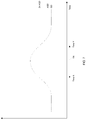
- FIG. 4 shows example curves of IOPS, latency, and queue depth versus time for particular data storage equipment 24 under evaluation.
- the IOPS (or throughput) of the data storage equipment 24 is relatively constant. Such may be the case in online banking, in online payments, as database transactions, etc. where the host computers 22 provide I/O requests 30 to the data storage equipment 24 in a relatively steady stream. Accordingly, the data storage equipment 24 may be viewed as processing a workload that exhibits OLTP-style behavior.
- Equation (1) shows how queue depth may be derived from IOPS and latency. Accordingly, the raw (or time-specific) queue depth (QD) at a particular time may be computed based on raw IOPS at that time and raw latency at that time. Moreover, a time series for at least some of this data may be depicted as shown in FIG. 7 .
- the specialized circuitry considers a performance impact event to possibly have occurred if the QD exceeds 2 times the AQD (i.e., the predefined threshold is “by a factor of 2”). Accordingly, if at least a portion of the QD time series exceeds 2 times the AQD, the specialized circuitry proceeds from 204 to 206 to perform closer evaluation. However, if no portion of the QD time series exceeds 2 times the AQD, the specialized circuitry proceeds from 204 to 210 .
- Such a closer evaluation situation may occur at 206 and/or at 214 in the procedure 200 ( FIG. 6 ) in accordance with certain embodiments. It is here, at 206 and 214 , where the specialized circuitry performs preliminary evaluation of certain data storage performance data to determine whether such data should be evaluated more closely.
- the specialized circuitry performs another evaluation operation to determine whether strong correlation exists between raw latency and I/O size during the evaluation window (i.e., between time X and time Y). Again, in accordance with certain embodiments, the specialized circuitry may apply one or more thresholds, parameters, and/or other criteria to delineate edge certain case situations.
- the procedure 200 may perform the procedure 300 during both the OLTP case and the OLAP case.
- the specialized circuitry may discover different results in each case. For example, the specialized circuitry may detect performance impact events occurring on some LUNs in the OLTP pass, and may detect performance impact events occurring on other LUNs in the OLAP pass.
- the above-described techniques do not merely collect, analyze, and display data. Rather, the disclosed techniques involve an improvement to the technology by diagnosing poor performance events that occur within data storage equipment 24 . With such techniques, other advantages are available as well such as changing the operation of the data storage equipment 24 (e.g., to reduce latency, to improve throughput, to migrate and/or change workloads, etc.), and so on.
Abstract
Description
-
- (A) receive queue depth metrics and other metrics (e.g., IOPS, latency, IO-size, percentage reads) from data storage performance data describing data storage performance of data storage equipment, at least some of the data storage performance data having been received through the communications interface,
- (B) perform a performance impact detection operation on the queue depth metrics to determine whether a performance impacting event has occurred on the data storage equipment, and
- (C) in response to a result of the performance impact detection operation indicating that a performance impacting event has occurred on the data storage equipment, launch a set of performance impact operations to address the performance impacting event that occurred on the data storage equipment.
-
- (A) receiving queue depth metrics and other metrics (e.g., IOPS, latency, IO-size, percentage reads) from data storage performance data describing data storage performance of the data storage equipment;
- (B) performing a performance impact detection operation on the queue depth metrics to determine whether a performance impacting event has occurred on the data storage equipment; and
- (C) in response to a result of the performance impact detection operation indicating that a performance impacting event has occurred on the data storage equipment, launching a set of performance impact operations to address the performance impacting event that occurred on the data storage equipment.
Queue Depth=IOPS×Latency Equation (1).
Claims (20)
Priority Applications (1)
| Application Number | Priority Date | Filing Date | Title |
|---|---|---|---|
| US16/390,534 US11023169B2 (en) | 2019-04-22 | 2019-04-22 | Identifying performance impact events in data storage equipment based on queue depth metrics |
Applications Claiming Priority (1)
| Application Number | Priority Date | Filing Date | Title |
|---|---|---|---|
| US16/390,534 US11023169B2 (en) | 2019-04-22 | 2019-04-22 | Identifying performance impact events in data storage equipment based on queue depth metrics |
Publications (2)
| Publication Number | Publication Date |
|---|---|
| US20200333978A1 US20200333978A1 (en) | 2020-10-22 |
| US11023169B2 true US11023169B2 (en) | 2021-06-01 |
Family
ID=72832375
Family Applications (1)
| Application Number | Title | Priority Date | Filing Date |
|---|---|---|---|
| US16/390,534 Active US11023169B2 (en) | 2019-04-22 | 2019-04-22 | Identifying performance impact events in data storage equipment based on queue depth metrics |
Country Status (1)
| Country | Link |
|---|---|
| US (1) | US11023169B2 (en) |
Cited By (2)
| Publication number | Priority date | Publication date | Assignee | Title |
|---|---|---|---|---|
| US11442639B2 (en) | 2020-04-14 | 2022-09-13 | EMC IP Holding Company LLC | Method, apparatus, and storage medium for managing stripe in storage system |
| US11886922B2 (en) | 2016-09-07 | 2024-01-30 | Pure Storage, Inc. | Scheduling input/output operations for a storage system |
Families Citing this family (1)
| Publication number | Priority date | Publication date | Assignee | Title |
|---|---|---|---|---|
| US20220382487A1 (en) * | 2019-12-31 | 2022-12-01 | Micron Technology, Inc. | Mobile storage random read performance estimation enhancements |
Citations (21)
| Publication number | Priority date | Publication date | Assignee | Title |
|---|---|---|---|---|
| EP1096737A2 (en) * | 1999-06-02 | 2001-05-02 | Nortel Networks Limited | Method and apparatus for queue management |
| US20020103923A1 (en) * | 2001-01-26 | 2002-08-01 | Jacob Cherian | System and method for matching storage device queue depth to server command queue depth |
| US6711137B1 (en) * | 1999-03-12 | 2004-03-23 | International Business Machines Corporation | System and method for analyzing and tuning a communications network |
| US20040244007A1 (en) * | 2003-05-28 | 2004-12-02 | International Business Machines Corporation | Workload balancing |
| US20070124728A1 (en) * | 2005-11-28 | 2007-05-31 | Mark Rosenbluth | Passing work between threads |
| US7739470B1 (en) * | 2006-10-20 | 2010-06-15 | Emc Corporation | Limit algorithm using queue depth to control application performance |
| US20100191876A1 (en) * | 2009-01-27 | 2010-07-29 | Muppirala Kishore Kumar | Method And System For Optimizing Network Input/Output Performance |
| US7949123B1 (en) * | 2004-09-28 | 2011-05-24 | Avaya Inc. | Wait time predictor for long shelf-life work |
| US8015327B1 (en) | 2007-09-17 | 2011-09-06 | Emc Corporation | Techniques for monitoring and managing wait queues |
| US8775549B1 (en) | 2007-09-27 | 2014-07-08 | Emc Corporation | Methods, systems, and computer program products for automatically adjusting a data replication rate based on a specified quality of service (QoS) level |
| US8868797B1 (en) | 2012-03-30 | 2014-10-21 | Emc Corporation | Techniques for automated discovery of storage devices and their performance characteristics |
| US8898357B1 (en) | 2010-03-31 | 2014-11-25 | Emc Corporation | Storage integration plugin for virtual servers |
| US20150120907A1 (en) * | 2013-10-29 | 2015-04-30 | Virtual Instruments Corporation | Storage area network queue depth profiler |
| US20150355861A1 (en) * | 2014-06-10 | 2015-12-10 | International Business Machines Corporation | Transfer size monitor, determination, and optimization engine for storage devices |
| US20160149766A1 (en) * | 2014-11-21 | 2016-05-26 | Pure Storage, Inc. | Cloud based management of storage systems |
| US9354813B1 (en) | 2012-12-28 | 2016-05-31 | Emc Corporation | Data storage system modeling |
| US20160197799A1 (en) * | 2015-01-05 | 2016-07-07 | Cisco Technology, Inc. | Distributed and adaptive computer network analytics |
| US9459799B1 (en) * | 2014-06-25 | 2016-10-04 | Emc Corporation | Identifying problematic application workloads based on associated response times |
| US9760392B1 (en) * | 2015-08-31 | 2017-09-12 | Veritas Technologies Llc | Adaptive throttling in hybrid storage environments |
| US9870434B1 (en) | 2014-06-20 | 2018-01-16 | EMC IP Holding Company LLC | Techniques for filtering workload and performance data |
| US10642764B1 (en) * | 2019-03-01 | 2020-05-05 | Western Digital Technologies, Inc. | Data transfer command latency of a host device |
-
2019
- 2019-04-22 US US16/390,534 patent/US11023169B2/en active Active
Patent Citations (22)
| Publication number | Priority date | Publication date | Assignee | Title |
|---|---|---|---|---|
| US6711137B1 (en) * | 1999-03-12 | 2004-03-23 | International Business Machines Corporation | System and method for analyzing and tuning a communications network |
| EP1096737A2 (en) * | 1999-06-02 | 2001-05-02 | Nortel Networks Limited | Method and apparatus for queue management |
| US20020103923A1 (en) * | 2001-01-26 | 2002-08-01 | Jacob Cherian | System and method for matching storage device queue depth to server command queue depth |
| US20040244007A1 (en) * | 2003-05-28 | 2004-12-02 | International Business Machines Corporation | Workload balancing |
| US7949123B1 (en) * | 2004-09-28 | 2011-05-24 | Avaya Inc. | Wait time predictor for long shelf-life work |
| US20070124728A1 (en) * | 2005-11-28 | 2007-05-31 | Mark Rosenbluth | Passing work between threads |
| US7739470B1 (en) * | 2006-10-20 | 2010-06-15 | Emc Corporation | Limit algorithm using queue depth to control application performance |
| US8015327B1 (en) | 2007-09-17 | 2011-09-06 | Emc Corporation | Techniques for monitoring and managing wait queues |
| US8775549B1 (en) | 2007-09-27 | 2014-07-08 | Emc Corporation | Methods, systems, and computer program products for automatically adjusting a data replication rate based on a specified quality of service (QoS) level |
| US20100191876A1 (en) * | 2009-01-27 | 2010-07-29 | Muppirala Kishore Kumar | Method And System For Optimizing Network Input/Output Performance |
| US8898357B1 (en) | 2010-03-31 | 2014-11-25 | Emc Corporation | Storage integration plugin for virtual servers |
| US8868797B1 (en) | 2012-03-30 | 2014-10-21 | Emc Corporation | Techniques for automated discovery of storage devices and their performance characteristics |
| US9354813B1 (en) | 2012-12-28 | 2016-05-31 | Emc Corporation | Data storage system modeling |
| US20150120907A1 (en) * | 2013-10-29 | 2015-04-30 | Virtual Instruments Corporation | Storage area network queue depth profiler |
| US20150355861A1 (en) * | 2014-06-10 | 2015-12-10 | International Business Machines Corporation | Transfer size monitor, determination, and optimization engine for storage devices |
| US9335945B2 (en) * | 2014-06-10 | 2016-05-10 | International Business Machines Corporation | Transfer size monitor, determination, and optimization engine for storage devices |
| US9870434B1 (en) | 2014-06-20 | 2018-01-16 | EMC IP Holding Company LLC | Techniques for filtering workload and performance data |
| US9459799B1 (en) * | 2014-06-25 | 2016-10-04 | Emc Corporation | Identifying problematic application workloads based on associated response times |
| US20160149766A1 (en) * | 2014-11-21 | 2016-05-26 | Pure Storage, Inc. | Cloud based management of storage systems |
| US20160197799A1 (en) * | 2015-01-05 | 2016-07-07 | Cisco Technology, Inc. | Distributed and adaptive computer network analytics |
| US9760392B1 (en) * | 2015-08-31 | 2017-09-12 | Veritas Technologies Llc | Adaptive throttling in hybrid storage environments |
| US10642764B1 (en) * | 2019-03-01 | 2020-05-05 | Western Digital Technologies, Inc. | Data transfer command latency of a host device |
Cited By (2)
| Publication number | Priority date | Publication date | Assignee | Title |
|---|---|---|---|---|
| US11886922B2 (en) | 2016-09-07 | 2024-01-30 | Pure Storage, Inc. | Scheduling input/output operations for a storage system |
| US11442639B2 (en) | 2020-04-14 | 2022-09-13 | EMC IP Holding Company LLC | Method, apparatus, and storage medium for managing stripe in storage system |
Also Published As
| Publication number | Publication date |
|---|---|
| US20200333978A1 (en) | 2020-10-22 |
Similar Documents
| Publication | Publication Date | Title |
|---|---|---|
| US11023169B2 (en) | Identifying performance impact events in data storage equipment based on queue depth metrics | |
| US7895398B2 (en) | System and method for dynamically adjusting the caching characteristics for each logical unit of a storage array | |
| US8346917B2 (en) | Unified enterprise level method and system for enhancing application and storage performance | |
| US7552276B2 (en) | System, method and program for managing storage | |
| CN107145432B (en) | Method for establishing model database and client | |
| US9336340B1 (en) | Evaluating management operations | |
| US9612758B1 (en) | Performing a pre-warm-up procedure via intelligently forecasting as to when a host computer will access certain host data | |
| US20160259742A1 (en) | Methods and systems for filtering collected qos data for predicting an expected range for future qos data | |
| US9804993B1 (en) | Data volume placement techniques | |
| US10067704B2 (en) | Method for optimizing storage configuration for future demand and system thereof | |
| US9658778B2 (en) | Method and system for monitoring and analyzing quality of service in a metro-cluster | |
| US20150263986A1 (en) | Relationship-Based Resource-Contention Analysis System and Method | |
| US20060259688A1 (en) | Highly available removable media storage network environment | |
| US10225158B1 (en) | Policy based system management | |
| US10310935B2 (en) | Dynamically restoring disks based on array properties | |
| CN105868056B (en) | Obtain the method, apparatus and secure virtual machine of deleted document in Windows virtual machine | |
| US10146450B1 (en) | Managing a pool of storage slices via consumption estimation based on historical data | |
| US10896007B2 (en) | Workload balancing in a distributed storage system | |
| US9459799B1 (en) | Identifying problematic application workloads based on associated response times | |
| US11281543B2 (en) | Application-level recovery from an enterprise-level image copy | |
| US11461250B2 (en) | Tuning data storage equipment based on comparing observed I/O statistics with expected I/O statistics which are defined by operating settings that control operation | |
| CN109672544B (en) | Data processing method and device and distributed storage system | |
| US20090164716A1 (en) | Adaptation of Contentious Storage Virtualization Configurations | |
| US20060107102A1 (en) | Checking storage reconfiguration | |
| US7721053B2 (en) | Intelligent logical unit provisioning |
Legal Events
| Date | Code | Title | Description |
|---|---|---|---|
| FEPP | Fee payment procedure |
Free format text: ENTITY STATUS SET TO UNDISCOUNTED (ORIGINAL EVENT CODE: BIG.); ENTITY STATUS OF PATENT OWNER: LARGE ENTITY |
|
| AS | Assignment |
Owner name: EMC IP HOLDING COMPANY LLC, MASSACHUSETTS Free format text: ASSIGNMENT OF ASSIGNORS INTEREST;ASSIGNORS:ARNOLD, ZACHARY;BEALE, PETER;SIGNING DATES FROM 20190416 TO 20190422;REEL/FRAME:049199/0953 |
|
| AS | Assignment |
Owner name: CREDIT SUISSE AG, CAYMAN ISLANDS BRANCH, NORTH CAROLINA Free format text: SECURITY AGREEMENT;ASSIGNORS:DELL PRODUCTS L.P.;EMC CORPORATION;EMC IP HOLDING COMPANY LLC;AND OTHERS;REEL/FRAME:050405/0534 Effective date: 20190917 |
|
| AS | Assignment |
Owner name: THE BANK OF NEW YORK MELLON TRUST COMPANY, N.A., AS COLLATERAL AGENT, TEXAS Free format text: PATENT SECURITY AGREEMENT (NOTES);ASSIGNORS:DELL PRODUCTS L.P.;EMC CORPORATION;EMC IP HOLDING COMPANY LLC;AND OTHERS;REEL/FRAME:050724/0466 Effective date: 20191010 |
|
| AS | Assignment |
Owner name: THE BANK OF NEW YORK MELLON TRUST COMPANY, N.A., TEXAS Free format text: SECURITY AGREEMENT;ASSIGNORS:CREDANT TECHNOLOGIES INC.;DELL INTERNATIONAL L.L.C.;DELL MARKETING L.P.;AND OTHERS;REEL/FRAME:053546/0001 Effective date: 20200409 |
|
| AS | Assignment |
Owner name: THE BANK OF NEW YORK MELLON TRUST COMPANY, N.A., AS COLLATERAL AGENT, TEXAS Free format text: SECURITY INTEREST;ASSIGNORS:DELL PRODUCTS L.P.;EMC CORPORATION;EMC IP HOLDING COMPANY LLC;REEL/FRAME:053311/0169 Effective date: 20200603 |
|
| STPP | Information on status: patent application and granting procedure in general |
Free format text: DOCKETED NEW CASE - READY FOR EXAMINATION |
|
| STPP | Information on status: patent application and granting procedure in general |
Free format text: NOTICE OF ALLOWANCE MAILED -- APPLICATION RECEIVED IN OFFICE OF PUBLICATIONS |
|
| STPP | Information on status: patent application and granting procedure in general |
Free format text: PUBLICATIONS -- ISSUE FEE PAYMENT VERIFIED |
|
| STCF | Information on status: patent grant |
Free format text: PATENTED CASE |
|
| AS | Assignment |
Owner name: WYSE TECHNOLOGY L.L.C., CALIFORNIA Free format text: RELEASE OF SECURITY INTEREST AT REEL 050405 FRAME 0534;ASSIGNOR:CREDIT SUISSE AG, CAYMAN ISLANDS BRANCH;REEL/FRAME:058001/0001 Effective date: 20211101 Owner name: EMC IP HOLDING COMPANY LLC, TEXAS Free format text: RELEASE OF SECURITY INTEREST AT REEL 050405 FRAME 0534;ASSIGNOR:CREDIT SUISSE AG, CAYMAN ISLANDS BRANCH;REEL/FRAME:058001/0001 Effective date: 20211101 Owner name: EMC CORPORATION, MASSACHUSETTS Free format text: RELEASE OF SECURITY INTEREST AT REEL 050405 FRAME 0534;ASSIGNOR:CREDIT SUISSE AG, CAYMAN ISLANDS BRANCH;REEL/FRAME:058001/0001 Effective date: 20211101 Owner name: DELL PRODUCTS L.P., TEXAS Free format text: RELEASE OF SECURITY INTEREST AT REEL 050405 FRAME 0534;ASSIGNOR:CREDIT SUISSE AG, CAYMAN ISLANDS BRANCH;REEL/FRAME:058001/0001 Effective date: 20211101 |
|
| AS | Assignment |
Owner name: DELL MARKETING CORPORATION (SUCCESSOR-IN-INTEREST TO WYSE TECHNOLOGY L.L.C.), TEXAS Free format text: RELEASE OF SECURITY INTEREST IN PATENTS PREVIOUSLY RECORDED AT REEL/FRAME (050724/0466);ASSIGNOR:THE BANK OF NEW YORK MELLON TRUST COMPANY, N.A., AS NOTES COLLATERAL AGENT;REEL/FRAME:060753/0486 Effective date: 20220329 Owner name: EMC IP HOLDING COMPANY LLC, TEXAS Free format text: RELEASE OF SECURITY INTEREST IN PATENTS PREVIOUSLY RECORDED AT REEL/FRAME (050724/0466);ASSIGNOR:THE BANK OF NEW YORK MELLON TRUST COMPANY, N.A., AS NOTES COLLATERAL AGENT;REEL/FRAME:060753/0486 Effective date: 20220329 Owner name: EMC CORPORATION, MASSACHUSETTS Free format text: RELEASE OF SECURITY INTEREST IN PATENTS PREVIOUSLY RECORDED AT REEL/FRAME (050724/0466);ASSIGNOR:THE BANK OF NEW YORK MELLON TRUST COMPANY, N.A., AS NOTES COLLATERAL AGENT;REEL/FRAME:060753/0486 Effective date: 20220329 Owner name: DELL PRODUCTS L.P., TEXAS Free format text: RELEASE OF SECURITY INTEREST IN PATENTS PREVIOUSLY RECORDED AT REEL/FRAME (050724/0466);ASSIGNOR:THE BANK OF NEW YORK MELLON TRUST COMPANY, N.A., AS NOTES COLLATERAL AGENT;REEL/FRAME:060753/0486 Effective date: 20220329 Owner name: EMC IP HOLDING COMPANY LLC, TEXAS Free format text: RELEASE OF SECURITY INTEREST IN PATENTS PREVIOUSLY RECORDED AT REEL/FRAME (053311/0169);ASSIGNOR:THE BANK OF NEW YORK MELLON TRUST COMPANY, N.A., AS NOTES COLLATERAL AGENT;REEL/FRAME:060438/0742 Effective date: 20220329 Owner name: EMC CORPORATION, MASSACHUSETTS Free format text: RELEASE OF SECURITY INTEREST IN PATENTS PREVIOUSLY RECORDED AT REEL/FRAME (053311/0169);ASSIGNOR:THE BANK OF NEW YORK MELLON TRUST COMPANY, N.A., AS NOTES COLLATERAL AGENT;REEL/FRAME:060438/0742 Effective date: 20220329 Owner name: DELL PRODUCTS L.P., TEXAS Free format text: RELEASE OF SECURITY INTEREST IN PATENTS PREVIOUSLY RECORDED AT REEL/FRAME (053311/0169);ASSIGNOR:THE BANK OF NEW YORK MELLON TRUST COMPANY, N.A., AS NOTES COLLATERAL AGENT;REEL/FRAME:060438/0742 Effective date: 20220329 |