US11022775B2 - Lens apparatus and optical apparatus - Google Patents
Lens apparatus and optical apparatus Download PDFInfo
- Publication number
- US11022775B2 US11022775B2 US16/257,168 US201916257168A US11022775B2 US 11022775 B2 US11022775 B2 US 11022775B2 US 201916257168 A US201916257168 A US 201916257168A US 11022775 B2 US11022775 B2 US 11022775B2
- Authority
- US
- United States
- Prior art keywords
- barrel
- cam
- lens
- optical axis
- guide
- Prior art date
- Legal status (The legal status is an assumption and is not a legal conclusion. Google has not performed a legal analysis and makes no representation as to the accuracy of the status listed.)
- Expired - Fee Related, expires
Links
Images


Classifications
-
- G—PHYSICS
- G02—OPTICS
- G02B—OPTICAL ELEMENTS, SYSTEMS OR APPARATUS
- G02B7/00—Mountings, adjusting means, or light-tight connections, for optical elements
- G02B7/02—Mountings, adjusting means, or light-tight connections, for optical elements for lenses
- G02B7/04—Mountings, adjusting means, or light-tight connections, for optical elements for lenses with mechanism for focusing or varying magnification
- G02B7/10—Mountings, adjusting means, or light-tight connections, for optical elements for lenses with mechanism for focusing or varying magnification by relative axial movement of several lenses, e.g. of varifocal objective lens
-
- G—PHYSICS
- G02—OPTICS
- G02B—OPTICAL ELEMENTS, SYSTEMS OR APPARATUS
- G02B13/00—Optical objectives specially designed for the purposes specified below
- G02B13/02—Telephoto objectives, i.e. systems of the type + - in which the distance from the front vertex to the image plane is less than the equivalent focal length
-
- G—PHYSICS
- G02—OPTICS
- G02B—OPTICAL ELEMENTS, SYSTEMS OR APPARATUS
- G02B13/00—Optical objectives specially designed for the purposes specified below
- G02B13/06—Panoramic objectives; So-called "sky lenses" including panoramic objectives having reflecting surfaces
-
- G—PHYSICS
- G02—OPTICS
- G02B—OPTICAL ELEMENTS, SYSTEMS OR APPARATUS
- G02B7/00—Mountings, adjusting means, or light-tight connections, for optical elements
- G02B7/02—Mountings, adjusting means, or light-tight connections, for optical elements for lenses
- G02B7/021—Mountings, adjusting means, or light-tight connections, for optical elements for lenses for more than one lens
-
- G—PHYSICS
- G02—OPTICS
- G02B—OPTICAL ELEMENTS, SYSTEMS OR APPARATUS
- G02B7/00—Mountings, adjusting means, or light-tight connections, for optical elements
- G02B7/02—Mountings, adjusting means, or light-tight connections, for optical elements for lenses
- G02B7/023—Mountings, adjusting means, or light-tight connections, for optical elements for lenses permitting adjustment
Definitions
- the present invention relates to a lens barrel and an optical apparatus using the same, such as an interchangeable lens and an imaging apparatus.
- Some lens barrels have a zoom mechanism configured to change an imaging angle of view by moving a plurality of lens units in an imaging optical system in an optical axis direction (or by changing intervals among the plurality of lens units). It is necessary for a higher zoom magnification in this lens barrel to increase a moving amount of each lens unit. In this case, it is necessary to increase a rotating amount of a cam barrel from a wide-angle end to a telephoto end so that the user can rotate the cam barrel with a small operation torque and greatly move each lens unit, but consequently the number of cams in one cam barrel is limited.
- a first cam barrel is rotated around an optical axis
- a cam in the first cam barrel moves a second cam barrel disposed inside the first cam barrel in the optical axis direction and rotates it around the optical axis
- a cam in the second cam barrel moves the lens unit in the optical axis direction.
- the above two-stage cam barrel causes an outer diameter of the lens barrel to be larger.
- the present invention provides a lens barrel which can move a plurality of lens units while preventing an outer diameter from increasing.
- a lens barrel includes a first guide barrel configured to guide linear movements of a first lens and a second lens in an optical axis direction, a first cam barrel rotatable around an optical axis relative to the first guide barrel and including a first cam configured to move the first lens in the optical axis direction by a rotation of the first cam barrel, and a second cam barrel rotatable around the optical axis relative to the first guide barrel by the rotation of the first cam barrel, and including a second cam configured to move the second lens in the optical axis direction by a rotation of a second cam barrel.
- An optical apparatus including the above lens barrel also constitutes another aspect of the present invention.
- FIG. 1 is an exploded perspective view of a lens barrel according to an embodiment of the present invention.
- FIG. 2 is a sectional view of the lens barrel in a wide-angle state according to the embodiment.
- FIG. 3 is a sectional view of the lens barrel in a telephoto state according to the embodiment.
- FIG. 4 is a sectional view of a linear movement barrel according to the embodiment.
- FIG. 5 is a sectional view of a second lens holder according to the embodiment.
- FIG. 6 is a sectional view of a third lens holder according to the embodiment.
- FIG. 7 is a sectional view of a fourth lens holder according to the embodiment.
- FIG. 8 is a perspective view of a second cam barrel according to the embodiment.
- FIG. 9 is a sectional view of the second cam barrel and a second guide barrel according to the embodiment.
- FIG. 10 is a perspective view of the second guide barrel according to the embodiment.
- FIG. 11 is a sectional view of the linear movement barrel and the second cam barrel according to the embodiment.
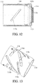
- FIG. 12 is a sectional view of an operating ring according to the embodiment.
- FIG. 13 is a perspective view of a first cam barrel according to the embodiment.
- FIG. 14 is a perspective view of a first guide barrel according to the embodiment.
- FIG. 15 is a side view of the first guide barrel and the first cam barrel in the wide-angle state according to the embodiment.
- FIG. 16 is a side view of the first guide barrel and the first cam barrel in the telephoto state according to the embodiment.
- FIG. 17 is a sectional view containing a second cam follower in the lens barrel (wide-angle state) according to the embodiment.
- FIG. 18 is a sectional view containing a sixth cam follower in the lens barrel (wide-angle state) according to the embodiment.
- FIG. 19 is a sectional view containing a second linear movement follower in the lens barrel (wide-angle state) according to the embodiment.
- FIG. 20 is a sectional view of the lens barrel (wide-angle state) according to the embodiment.
- FIG. 21 is a sectional view of the lens barrel (telephoto state) according to the embodiment.
- FIG. 1 is an exploded view of a lens barrel according to one embodiment of the present invention.
- An interchangeable lens as an optical apparatus is configured with the lens barrel.
- a lens barrel having the same structure as that in this embodiment may be used for a lens integrated camera as an optical apparatus.
- FIGS. 2 and 3 illustrate sections of the wide-angle (end) state and the telephoto (end) state in the lens barrel according to this embodiment.
- A is an optical axis of a lens barrel (or an imaging lens described later), and a direction in which the optical axis A extends will be referred to as an optical axis direction.
- a direction orthogonal to the optical axis direction will be referred to as a radial direction, and a direction around the optical axis will be also referred to as a circumferential direction or a rotating direction.
- the imaging lens includes, in order from an object side to an image side, a first lens unit 103 , a second lens unit 101 , a third lens unit 105 , and a fourth lens unit 107 .
- the third lens unit 105 and the fourth lens unit 107 correspond to a first lens including a plurality of lens units
- the second lens unit 101 corresponds to a second lens.
- the first lens unit 103 corresponds to a third lens.
- Reference numeral 104 denotes a linear movement barrel (or cylinder) configured to hold the first lens unit 103
- reference numeral 102 denotes a second lens holder configured to hold the second lens unit 101
- Reference numeral 106 denotes a third lens holder configured to hold the third lens unit 105
- reference numeral 108 denotes a fourth lens holder configured to hold the fourth lens unit 107 .
- Reference numeral 111 denotes a first guide barrel
- reference numeral 113 denotes a fixed barrel configured to fix the first guide barrel 111
- a mount 114 detachably attached to an unillustrated lens interchangeable type camera is attached to the fixed barrel 113 .
- a first cam barrel 110 rotatable around the optical axis relative to the first guide barrel 111 and movable in the optical axis direction is disposed on the outer circumference of the first guide barrel 111 .
- a second cam barrel 109 is provided on the outer circumference of the first cam barrel 110 , rotatable around the optical axis by the rotation of the first cam barrel 110 , and movable in the optical axis direction relative to the first cam barrel 110 .
- a second guide barrel 112 is provided on the outer circumference of the second cam barrel 109 , movable in the optical axis direction with the second cam barrel 109 , configured to rotatably hold the second cam barrel 109 , and spaced from the second cam barrel 109 in a radial direction.
- a linear movement barrel 104 is disposed in this space or gap.
- An operating ring 115 bayonet-connected with a fixed barrel 113 on the outer circumference of the second guide barrel 112 and rotatably held around the optical axis at a fixed position in the optical axis direction. Rubber 116 is wound around the outer circumference of the operating ring 115 for a slip prevention when the user rotates the operating ring 115 .
- the first, second, third and fourth lens units 103 , 101 , 105 , and 107 independently move in the optical axis direction for a magnification variation (zooming).
- This embodiment realizes a high zoom magnification, in particular, by setting a large moving amount (large extending amount) to the first lens unit 103 .
- This embodiment can significantly extend the first lens unit 103 by the configuration that extends, relative to the first cam barrel 110 , the second cam barrel 109 that extends the linear movement barrel 104 .
- each cam barrel, each guide barrel, operating ring, and each holding barrel will be described below.
- the cam groove portions, the guide groove portions, and the cam followers, which will be described later, are provided at three positions at substantially regular intervals in the circumferential direction in each cam barrel, each guide barrel, the operating ring, and each lens holder.
- FIG. 4 illustrates a section of the first lens unit 103 and the linear movement barrel 104 holding the same.
- a first linear movement follower 121 is provided on the outer circumferential portion of the linear movement barrel 104 .
- a first cam follower 123 is provided on the inner circumferential portion of the linear movement barrel 104 .
- FIG. 5 illustrates a section of the second lens unit 101 and the second lens holder 102 holding it.
- a left view of FIG. 5 illustrates a section containing the second cam follower 124 in which the second lens unit 101 and the second lens holder 102 are provided on the front side (object side) of the outer circumferential portion of the second lens holder 102 .
- a right view illustrates a section containing a second linear movement follower 125 provided on a rear side (image side) of the outer circumferential portion of the second lens holder 102 .
- the second cam follower 124 and the second linear movement follower 125 have a first cylindrical portion 124 a and a second cylindrical portion 125 a , and an outer diameter of the first cylindrical portion 124 a is set larger than an outer diameter of the second cylindrical portion 125 a .
- An external force (impact) may be applied to the interchangeable lens from the object side to the image side.
- a second cam follower 124 engaged with a second cam groove portion 109 a tilted to the optical axis direction receives a force larger than a second linear movement follower 125 engaged with a second guide groove portion 111 a (described later) extending in the optical axis direction.
- the outer diameter of the second cam follower 124 is made larger than the outer diameter of the second linear movement follower 125 so as to prevent the second cam follower 124 from deforming (crushing) due to the external force.
- the second linear movement follower 125 and the second cam follower 124 are provided with mutually different phases in the circumferential direction of the second lens holder 102 . The reason for this configuration will be described later.
- FIG. 6 illustrates a section of the third lens unit 105 and the third lens holder 106 holding it.
- a third cam follower 126 is provided on the outer circumferential portion of the third lens holder 106 .
- FIG. 7 illustrates a section of the fourth lens unit 107 and the fourth lens holder 108 holding it.
- a fourth cam follower 127 is provided on the outer circumferential portion of the fourth lens holder 108 .
- FIG. 8 is a perspective view of the second cam barrel 109 .
- the second cam barrel 109 includes a first cam groove portion 109 b engaged with the first cam follower 123 in the linear movement barrel 104 and a second cam groove portion 109 a engaged with the second cam follower 124 in the second lens holder 102 .
- the second cam groove portion 109 a corresponds to the second cam.
- the second cam barrel 109 includes a rotation connecting groove portion 109 d engaged with a rotation connecting pin 131 provided to the first cam barrel 110 , as described later.
- the rotation connecting groove portion 109 d linearly extends in the optical axis direction.
- the rotation connecting pins 131 and the rotation connecting groove portions 109 d are provided at three positions at substantially regular intervals in the circumferential direction in the first and second cam barrels 110 and 109 .
- the second cam barrel 109 includes bayonet claws 109 c at three positions at substantially regular intervals in the circumferential direction at the outer circumferential rear end portion thereof. These bayonet pawls 109 c are engaged with bayonet grooves 112 b formed so as to extend in the circumferential direction at the inner circumferential rear end portion of the second guide barrel 112 . Thereby, the second guide barrel 112 holds the second cam barrel 109 so as to be movable integrally in the optical axis direction and rotatable around the optical axis.
- FIG. 9 illustrates a section when the second cam barrel 109 is incorporated into the second guide barrel 112 .
- FIG. 10 is a perspective view of the second guide barrel 112 .
- FIG. 11 illustrates a section when the linear movement tube 104 is disposed between the second guide barrel 112 and the second cam barrel 109 .
- a sixth cam follower 128 is provided at the inner circumferential rear end portion of the second guide barrel 112 .
- the sixth cam follower 128 is engaged with the sixth cam groove portion 110 a provided on the first cam barrel 110 .
- the sixth cam groove portion 110 a and the sixth cam follower 128 constitute a first cam mechanism.
- the first cam follower 123 provided to the linear movement barrel 104 is engaged with the first cam groove portion 109 b in the second cam barrel 109 .
- a first linear follower 121 provided on the linear movement barrel 104 is engaged with a first guide groove portion 112 a ( FIG. 11 ) provided at the inner circumferential portion of the second guide barrel 112 .
- This configuration rotates the second cam barrel 109 around the optical axis, and linearly moves the linear movement barrel 104 in the optical axis direction.
- This embodiment arranges, in order from a radially inner side, the second cam barrel 109 , the linear movement barrel 104 , and the second guide barrel 112 .
- the linear movement barrel 104 is held between the second cam barrel 109 and the second guide barrel 112 .
- the outer circumferential surface of the second guide barrel 112 becomes an external surface of the lens barrel.
- the first guide groove portion 112 a in the second guide barrel 112 is formed as a bottomed groove portion which opens radially inwardly and does not perforate the second guide barrel 112 in the radial direction.
- the first guide groove portion 112 a is formed so as not to expose to the external appearance.
- a zoom cam follower 129 is provided on the outer circumferential portion of the second guide barrel 112 .
- the zoom cam follower 129 is engaged with a zoom cam groove portion 115 a provided on the inner circumferential portion of the operating ring 115 .
- FIG. 12 illustrates a section of the fixed barrel 113 to which the operating ring 115 around which the rubber 116 is wound and the mount 114 are attached.
- the operating ring 115 is held rotatably around the optical axis at a fixed position in the optical axis direction by the fixed barrel 113 because bayonet claws 113 b provided at three positions at substantially regular intervals in the circumferential direction of the fixed barrel 113 are engaged with a bayonet groove portion 115 b formed so as to extend in the circumferential direction at the outer circumferential rear end portion.
- the operating ring 115 has a zoom cam groove portion 115 a .
- the zoom cam follower 129 provided in the second guide barrel 112 is engaged with the zoom cam groove portion 115 a .
- the zoom cam groove portion 115 a and the zoom cam follower 129 constitute a third cam mechanism.
- FIG. 13 is a perspective view of the first cam barrel 110
- FIG. 14 is a perspective view of the first guide barrel 111
- FIG. 15 illustrates the first cam barrel 110 incorporated into the first guide barrel 111
- FIG. 16 illustrates the second cam barrel 109 assembled into the first guide barrel 111 and the first cam barrel 110 .
- the first cam barrel 110 includes the rotation connecting pin 131 at its outer circumferential portion engaged with the rotation connecting groove portion 109 d provided in the second cam barrel 109 , and a sixth cam groove portion 110 a with which the sixth cam follower 128 of the second guide barrel 112 is engaged.
- the first cam barrel 110 further includes a third cam groove portion 110 b engaged with the third cam follower 126 in the third lens holder 106 , a fourth cam groove portion 110 b engaged with the fourth cam follower 127 in the fourth lens holder 108 , and a fourth cam groove 110 c engaged with the fourth cam follower 127 in the fourth lens holder 108 .
- the third cam groove portion 110 b and the fourth cam groove portion 110 c correspond to the first cam.
- the first cam barrel 110 further includes a fifth cam groove portion 110 d engaged with a fifth cam follower 130 provided on the outer circumferential portion of the first guide barrel 111 .
- the fifth cam follower 130 and the fifth cam groove portion 110 d constitute a second cam mechanism.
- the first guide barrel 111 further includes a second guide groove portion 111 a engaged with the second linear movement follower 125 as a portion guided by the second lens holder 102 , and a sixth guide groove portion 111 b engaged with the sixth cam follower 128 in the guide barrel 112 .
- the first guide barrel 111 further includes a third guide groove portion 111 c engaged with the third cam follower 126 in the third lens holder 106 and the fourth cam follower 127 in the fourth lens holder 108 .
- FIGS. 17, 18 and 19 illustrate different sections of the lens barrel in the wide-angle state according to this embodiment.
- the second cam follower 124 in the second lens holder 102 is engaged with the second cam groove portion 109 a in the second cam barrel 109 .
- the zoom cam groove portion 115 a As the operating ring 115 is rotated, the zoom cam groove portion 115 a generates a force for moving the second guide barrel 112 in the optical axis direction together with the zoom cam follower 129 . Then, as illustrated in FIG. 18 , the sixth cam follower 128 provided to the second guide barrel 112 is guided in the optical axis direction by the sixth guide groove portion 111 b in the first guide barrel 111 . Thereby, the second guide barrel 111 moves in the optical axis direction with the second cam barrel 109 integrated with the second guide barrel 111 in the optical axis direction. As illustrated in FIG. 18 , since the sixth cam follower 128 is also engaged with the sixth cam groove 110 a in the first cam barrel 110 , as the second guide barrel 112 moves in the optical axis direction, the first cam barrel 110 rotates around the optical axis.
- the first cam barrel 110 rotated and moved in the optical axis direction since the fifth cam groove portion 110 d in the first cam barrel 110 is engaged with the fifth cam follower 130 provided on the outer circumferential portion in the first guide barrel 111 .
- the second cam barrel 109 is rotated around the optical axis by the engagement between the rotation connecting pin 131 and the rotation connecting groove portion 109 d .
- the first cam follower 123 in the linear movement barrel 104 is pressed by the first cam groove portion 109 b in the second cam barrel 109 that is rotated and moved in the optical axis direction, and the linear movement barrel 104 moves in the optical axis direction. Then, the linear movement barrel 104 (the first linear movement follower 121 ) is guided in the optical axis direction by the first guide groove portion 112 a in the second guide barrel 112 .
- the interchangeable lens with a high zoom magnification needs to make the overall length in the shortest state (wide-angle state) as short as possible, and to secure a large moving amount of each lens unit in zooming.
- This embodiment adopts a configuration that moves both the first cam barrel 110 and the second cam barrel 109 in the optical axis direction in zooming, and secures a large moving amount of each lens unit while shortening the overall length in the shortest state.
- the second cam follower 124 in the second lens holder 102 is engaged with the second cam groove portion 109 a in the second cam barrel 109 .
- the second linear follower 125 in the second lens holder 102 is engaged with the second guide groove portion 111 a in the first guide barrel 111 .
- the third cam follower 126 in the third lens holder 106 and the fourth cam follower 127 in the fourth lens holder 108 are engaged with the third cam groove portion 110 b and the fourth cam groove portion 110 c in the first cam barrel 110 .
- the third cam follower 126 and the fourth cam follower 127 are also engaged with the third guide groove portion 111 c in the first guide barrel 111 . Therefore, as the first cam barrel 110 rotates, the third lens holder 106 (the third lens unit 105 ) and the fourth lens holder 108 (the fourth lens unit 107 ) move in the optical axis direction.
- FIG. 20 illustrates a section of the lens barrel in the wide-angle state according to this embodiment.
- a first section including the second cam follower 124 provided on the second lens holder 102 is illustrated above the optical axis A.
- FIG. 20 illustrates a second section containing the second linear movement follower 125 below the optical axis A.
- the first section and the second section have different phases in the circumferential direction.
- reference numeral 124 b denotes a range from a mount reference surface 114 a as a contact surface with the camera in the mount 114 to a mount side surface (contact surface with the second cam groove portion 109 a ) of a cylindrical portion 124 a in the second cam follower 124 .
- Reference numeral 125 a denotes a range from the mount reference surface 114 a to the mount side surface of the cylindrical portion in the second linear movement follower 125 .
- FIG. 21 illustrates a section of the lens barrel in a telephoto state according to this embodiment.
- FIG. 21 also illustrates the first section above the optical axis A, and the second section below the optical axis A.
- reference numeral 124 c denotes a range from the mount reference surface 114 a to the mount side surface of the cylindrical portion 124 a in the second cam follower 124 .
- Reference numeral 125 b denotes a range from the mount reference surface 114 a to the mount side surface of the cylindrical portion in the second linear movement follower 125 .
- a first range 125 c is a range obtained by subtracting the range 125 a in the wide-angle state from the range 125 b in the telephoto state.
- a second range (moving range of the second cam follower 124 ) 124 d is a range obtained by subtracting the range 124 b in the wide-angle state from the range 124 c in the telephoto state.
- the lens barrel according to this embodiment is configured such that the first range 121 c and the second range 124 d overlap each other in the optical axis direction with different arrangement phases around the optical axis.
- the second cam groove portion 109 a and the second guide groove portion 111 a interfere each other since the second cam follower 124 and the second linear movement follower 125 overlap each other in a moving range in the optical axis direction.
- This embodiment provides the second cam follower 124 to the second cam barrel 109 , and the second guide groove portion 111 a to the first guide barrel 111 .
- the phases of the second cam follower 124 (the second cam groove portion 109 a ) and the second linear movement follower 125 (the second guide groove portion 111 a ) are made different from each other in the circumferential direction. This configuration can avoid the interference between the second guide groove portion 111 a and the second cam groove portion 109 a.
- the first cam barrel 110 includes many cam groove portions, such as the third and fourth cam groove portions 110 b and 110 c , the fifth cam groove portion 110 d for moving the first cam barrel 110 itself in the optical axis direction, and the sixth cam groove portion 110 a for rotating the barrel 110 .
- the first cam barrel 110 further includes the rotation connecting pin 131 for rotating the second cam barrel 109 . It is difficult for the space limitation to provide an additional cam groove portion to the first cam barrel 110 , and the reduced strength of the first cam member 110 due to the addition of the cam groove portion may be concerned.
- the outer diameter of the lens barrel may be increased or larger.
- this embodiment provides the second cam follower 124 to the second cam barrel 109 configured to move the linear movement barrel 104 , and the second guide groove portion 111 a to the first guide tube 111 configured to guide the third and fourth lens holders 106 and 108 .
- This configuration can secure necessary moving amounts of the first to fourth lens units 103 , 101 , 105 , and 107 while suppressing an increase in the outer diameter of the lens barrel.
- the imaging lens including the four lens units
- another imaging lens configuration may be adopted. While this embodiment omits a description of the operation of the lens unit for focusing, for example, if the imaging lens is a rear focus type lens, the third lens unit 105 and the fourth lens unit 107 may be moved in the optical axis direction for focusing. If the imaging lens is a front focus type lens, the first lens unit 103 is moved in the optical axis direction for focusing.
- the lens barrel that can move a plurality of lens units can be made smaller or reduced in diameter.
Landscapes
- Physics & Mathematics (AREA)
- General Physics & Mathematics (AREA)
- Optics & Photonics (AREA)
- Lens Barrels (AREA)
Abstract
Description
Claims (11)
Applications Claiming Priority (3)
| Application Number | Priority Date | Filing Date | Title |
|---|---|---|---|
| JP2018-013859 | 2018-01-30 | ||
| JP2018013859A JP7106281B2 (en) | 2018-01-30 | 2018-01-30 | Lens barrels and optical equipment |
| JPJP2018-013859 | 2020-01-30 |
Publications (2)
| Publication Number | Publication Date |
|---|---|
| US20190235204A1 US20190235204A1 (en) | 2019-08-01 |
| US11022775B2 true US11022775B2 (en) | 2021-06-01 |
Family
ID=67391429
Family Applications (1)
| Application Number | Title | Priority Date | Filing Date |
|---|---|---|---|
| US16/257,168 Expired - Fee Related US11022775B2 (en) | 2018-01-30 | 2019-01-25 | Lens apparatus and optical apparatus |
Country Status (2)
| Country | Link |
|---|---|
| US (1) | US11022775B2 (en) |
| JP (1) | JP7106281B2 (en) |
Families Citing this family (3)
| Publication number | Priority date | Publication date | Assignee | Title |
|---|---|---|---|---|
| EP3742047B1 (en) * | 2019-05-21 | 2021-07-07 | Zumtobel Lighting GmbH | Optical system for spotlight |
| CN211952438U (en) * | 2020-05-15 | 2020-11-17 | 瑞盎光电科技(广东)有限公司 | Lamp set |
| CN213957809U (en) * | 2020-11-06 | 2021-08-13 | 深圳市爱图仕影像器材有限公司 | A lamp and its optical lens |
Citations (2)
| Publication number | Priority date | Publication date | Assignee | Title |
|---|---|---|---|---|
| JPH10253867A (en) | 1997-03-14 | 1998-09-25 | Tamron Co Ltd | High power zoom lens |
| US20170153412A1 (en) * | 2015-11-26 | 2017-06-01 | Canon Kabushiki Kaisha | Lens barrel and optical apparatus |
Family Cites Families (2)
| Publication number | Priority date | Publication date | Assignee | Title |
|---|---|---|---|---|
| JP4455788B2 (en) * | 2001-09-25 | 2010-04-21 | 株式会社リコー | Zoom lens barrel |
| JP4594867B2 (en) * | 2006-01-16 | 2010-12-08 | 株式会社タムロン | Downsizing zoom lens |
-
2018
- 2018-01-30 JP JP2018013859A patent/JP7106281B2/en active Active
-
2019
- 2019-01-25 US US16/257,168 patent/US11022775B2/en not_active Expired - Fee Related
Patent Citations (2)
| Publication number | Priority date | Publication date | Assignee | Title |
|---|---|---|---|---|
| JPH10253867A (en) | 1997-03-14 | 1998-09-25 | Tamron Co Ltd | High power zoom lens |
| US20170153412A1 (en) * | 2015-11-26 | 2017-06-01 | Canon Kabushiki Kaisha | Lens barrel and optical apparatus |
Also Published As
| Publication number | Publication date |
|---|---|
| JP7106281B2 (en) | 2022-07-26 |
| US20190235204A1 (en) | 2019-08-01 |
| JP2019132947A (en) | 2019-08-08 |
Similar Documents
| Publication | Publication Date | Title |
|---|---|---|
| US7929228B2 (en) | Image pickup apparatus having lens barrel | |
| US8134784B2 (en) | Lens apparatus capable of performing extension/retraction operation with respect to image pickup apparatus body and image pickup apparatus having the same | |
| US9513462B2 (en) | Lens barrel and imaging apparatus | |
| US11022775B2 (en) | Lens apparatus and optical apparatus | |
| US6853500B2 (en) | Retracting mechanism of a zoom lens barrel | |
| CN113227865B (en) | Lens barrel and optical apparatus | |
| JP4969863B2 (en) | Lens barrel | |
| US7872810B2 (en) | Light shielding structure of an optical device | |
| US7876508B2 (en) | Lens drive unit, lens barrel, and image forming device | |
| US11029479B2 (en) | Lens barrel and optical apparatus | |
| US10877236B2 (en) | Lens barrel and camera | |
| US7515355B2 (en) | Compact zoom lens | |
| US7004672B2 (en) | Bayonet coupling for axially mounting one of two relatively rotatable ring-shaped members on the other | |
| JP4953969B2 (en) | Lens barrel and imaging device | |
| JP5570098B2 (en) | Lens barrel and camera | |
| US6906871B2 (en) | Cam mechanism for lens barrel | |
| JP5201811B2 (en) | Lens barrel and imaging device | |
| US8098446B2 (en) | Lens barrel and camera | |
| JP2004198499A (en) | Optical equipment | |
| JP6746909B2 (en) | Lens barrel and optical equipment | |
| US9477063B2 (en) | Lens barrel | |
| JP2014137521A (en) | Lens barrel, optical device and imaging device | |
| JP2009162860A (en) | Lens barrel | |
| JP2006030297A (en) | Lens barrel and camera | |
| JP2013156562A (en) | Lens barrel and imaging apparatus including the same |
Legal Events
| Date | Code | Title | Description |
|---|---|---|---|
| FEPP | Fee payment procedure |
Free format text: ENTITY STATUS SET TO UNDISCOUNTED (ORIGINAL EVENT CODE: BIG.); ENTITY STATUS OF PATENT OWNER: LARGE ENTITY |
|
| AS | Assignment |
Owner name: CANON KABUSHIKI KAISHA, JAPAN Free format text: ASSIGNMENT OF ASSIGNORS INTEREST;ASSIGNOR:ITO, HIROKI;REEL/FRAME:048812/0949 Effective date: 20190119 |
|
| STPP | Information on status: patent application and granting procedure in general |
Free format text: RESPONSE TO NON-FINAL OFFICE ACTION ENTERED AND FORWARDED TO EXAMINER |
|
| STPP | Information on status: patent application and granting procedure in general |
Free format text: NOTICE OF ALLOWANCE MAILED -- APPLICATION RECEIVED IN OFFICE OF PUBLICATIONS |
|
| STPP | Information on status: patent application and granting procedure in general |
Free format text: PUBLICATIONS -- ISSUE FEE PAYMENT RECEIVED |
|
| STPP | Information on status: patent application and granting procedure in general |
Free format text: PUBLICATIONS -- ISSUE FEE PAYMENT VERIFIED |
|
| STCF | Information on status: patent grant |
Free format text: PATENTED CASE |
|
| FEPP | Fee payment procedure |
Free format text: MAINTENANCE FEE REMINDER MAILED (ORIGINAL EVENT CODE: REM.); ENTITY STATUS OF PATENT OWNER: LARGE ENTITY |
|
| LAPS | Lapse for failure to pay maintenance fees |
Free format text: PATENT EXPIRED FOR FAILURE TO PAY MAINTENANCE FEES (ORIGINAL EVENT CODE: EXP.); ENTITY STATUS OF PATENT OWNER: LARGE ENTITY |
|
| STCH | Information on status: patent discontinuation |
Free format text: PATENT EXPIRED DUE TO NONPAYMENT OF MAINTENANCE FEES UNDER 37 CFR 1.362 |
|
| FP | Lapsed due to failure to pay maintenance fee |
Effective date: 20250601 |