US11022109B2 - Double acting linear electrical submersible pump and method for its operation - Google Patents
Double acting linear electrical submersible pump and method for its operation Download PDFInfo
- Publication number
- US11022109B2 US11022109B2 US16/051,921 US201816051921A US11022109B2 US 11022109 B2 US11022109 B2 US 11022109B2 US 201816051921 A US201816051921 A US 201816051921A US 11022109 B2 US11022109 B2 US 11022109B2
- Authority
- US
- United States
- Prior art keywords
- fluid
- plunger
- pump module
- cylinder
- volume
- Prior art date
- Legal status (The legal status is an assumption and is not a legal conclusion. Google has not performed a legal analysis and makes no representation as to the accuracy of the status listed.)
- Active, expires
Links
- 238000000034 method Methods 0.000 title claims description 5
- 239000012530 fluid Substances 0.000 claims abstract description 86
- 238000001914 filtration Methods 0.000 claims abstract description 17
- 238000000926 separation method Methods 0.000 claims abstract description 15
- 238000004891 communication Methods 0.000 claims abstract description 6
- 230000033001 locomotion Effects 0.000 claims description 12
- 230000005484 gravity Effects 0.000 claims description 7
- 238000007789 sealing Methods 0.000 claims description 4
- 239000002245 particle Substances 0.000 claims description 3
- 238000005086 pumping Methods 0.000 abstract description 18
- 239000003129 oil well Substances 0.000 description 13
- 238000013461 design Methods 0.000 description 8
- 239000012535 impurity Substances 0.000 description 6
- 238000010276 construction Methods 0.000 description 4
- 238000006073 displacement reaction Methods 0.000 description 3
- 239000000463 material Substances 0.000 description 3
- 230000005540 biological transmission Effects 0.000 description 2
- 238000010586 diagram Methods 0.000 description 2
- 230000000694 effects Effects 0.000 description 2
- 230000009931 harmful effect Effects 0.000 description 2
- 238000009434 installation Methods 0.000 description 2
- 239000007788 liquid Substances 0.000 description 2
- 229910000831 Steel Inorganic materials 0.000 description 1
- 238000013459 approach Methods 0.000 description 1
- 230000001174 ascending effect Effects 0.000 description 1
- 238000006243 chemical reaction Methods 0.000 description 1
- 230000007797 corrosion Effects 0.000 description 1
- 238000005260 corrosion Methods 0.000 description 1
- 230000008878 coupling Effects 0.000 description 1
- 238000010168 coupling process Methods 0.000 description 1
- 238000005859 coupling reaction Methods 0.000 description 1
- 239000011152 fibreglass Substances 0.000 description 1
- 239000002783 friction material Substances 0.000 description 1
- 238000002955 isolation Methods 0.000 description 1
- 230000007257 malfunction Effects 0.000 description 1
- 238000004519 manufacturing process Methods 0.000 description 1
- 239000002184 metal Substances 0.000 description 1
- 238000001556 precipitation Methods 0.000 description 1
- 239000010959 steel Substances 0.000 description 1
- 238000013519 translation Methods 0.000 description 1
- 238000010977 unit operation Methods 0.000 description 1
Images


Classifications
-
- E—FIXED CONSTRUCTIONS
- E21—EARTH OR ROCK DRILLING; MINING
- E21B—EARTH OR ROCK DRILLING; OBTAINING OIL, GAS, WATER, SOLUBLE OR MELTABLE MATERIALS OR A SLURRY OF MINERALS FROM WELLS
- E21B43/00—Methods or apparatus for obtaining oil, gas, water, soluble or meltable materials or a slurry of minerals from wells
- E21B43/12—Methods or apparatus for controlling the flow of the obtained fluid to or in wells
- E21B43/121—Lifting well fluids
- E21B43/128—Adaptation of pump systems with down-hole electric drives
-
- F—MECHANICAL ENGINEERING; LIGHTING; HEATING; WEAPONS; BLASTING
- F04—POSITIVE - DISPLACEMENT MACHINES FOR LIQUIDS; PUMPS FOR LIQUIDS OR ELASTIC FLUIDS
- F04B—POSITIVE-DISPLACEMENT MACHINES FOR LIQUIDS; PUMPS
- F04B17/00—Pumps characterised by combination with, or adaptation to, specific driving engines or motors
- F04B17/03—Pumps characterised by combination with, or adaptation to, specific driving engines or motors driven by electric motors
-
- F—MECHANICAL ENGINEERING; LIGHTING; HEATING; WEAPONS; BLASTING
- F04—POSITIVE - DISPLACEMENT MACHINES FOR LIQUIDS; PUMPS FOR LIQUIDS OR ELASTIC FLUIDS
- F04B—POSITIVE-DISPLACEMENT MACHINES FOR LIQUIDS; PUMPS
- F04B19/00—Machines or pumps having pertinent characteristics not provided for in, or of interest apart from, groups F04B1/00 - F04B17/00
- F04B19/20—Other positive-displacement pumps
- F04B19/22—Other positive-displacement pumps of reciprocating-piston type
-
- F—MECHANICAL ENGINEERING; LIGHTING; HEATING; WEAPONS; BLASTING
- F04—POSITIVE - DISPLACEMENT MACHINES FOR LIQUIDS; PUMPS FOR LIQUIDS OR ELASTIC FLUIDS
- F04B—POSITIVE-DISPLACEMENT MACHINES FOR LIQUIDS; PUMPS
- F04B47/00—Pumps or pumping installations specially adapted for raising fluids from great depths, e.g. well pumps
- F04B47/06—Pumps or pumping installations specially adapted for raising fluids from great depths, e.g. well pumps having motor-pump units situated at great depth
-
- F—MECHANICAL ENGINEERING; LIGHTING; HEATING; WEAPONS; BLASTING
- F04—POSITIVE - DISPLACEMENT MACHINES FOR LIQUIDS; PUMPS FOR LIQUIDS OR ELASTIC FLUIDS
- F04B—POSITIVE-DISPLACEMENT MACHINES FOR LIQUIDS; PUMPS
- F04B5/00—Machines or pumps with differential-surface pistons
- F04B5/02—Machines or pumps with differential-surface pistons with double-acting pistons
-
- F—MECHANICAL ENGINEERING; LIGHTING; HEATING; WEAPONS; BLASTING
- F04—POSITIVE - DISPLACEMENT MACHINES FOR LIQUIDS; PUMPS FOR LIQUIDS OR ELASTIC FLUIDS
- F04B—POSITIVE-DISPLACEMENT MACHINES FOR LIQUIDS; PUMPS
- F04B53/00—Component parts, details or accessories not provided for in, or of interest apart from, groups F04B1/00 - F04B23/00 or F04B39/00 - F04B47/00
- F04B53/14—Pistons, piston-rods or piston-rod connections
- F04B53/144—Adaptation of piston-rods
-
- F—MECHANICAL ENGINEERING; LIGHTING; HEATING; WEAPONS; BLASTING
- F04—POSITIVE - DISPLACEMENT MACHINES FOR LIQUIDS; PUMPS FOR LIQUIDS OR ELASTIC FLUIDS
- F04B—POSITIVE-DISPLACEMENT MACHINES FOR LIQUIDS; PUMPS
- F04B53/00—Component parts, details or accessories not provided for in, or of interest apart from, groups F04B1/00 - F04B23/00 or F04B39/00 - F04B47/00
- F04B53/20—Filtering
Definitions
- the invention relates to reciprocating piston pumps, in particular, to a reciprocating double acting well pump driven by a linear submersible permanent magnet motor.
- General approach to recovered borehole fluid ascent to the surface includes utilization of a displacement pump driven by a mechanical drive.
- sucker-rod pumps reciprocating of which is provided by a sucker-rod string.
- the sucker-rod pump unit consists of the displacement pump located at the bottom of an oil well tubing.
- the unit includes a piston moving linearly within the oil well tubing by means of steel or fiberglass rods. Linear movement of the pump rods is transmitted from the surface by means of a beam-type construction, designed to ascend and descend alternately the pump rods, thereby ensuring reciprocating movement of the pump piston.
- An ordinary solving of this problem involves utilization of well pumps installed in the lower part of the oil well tubing.
- This kind of equipment includes downhole reciprocating double-acting pumps.
- a generic aspect of such pumps is that both strokes of a pump plunger are operational in order to maximize the efficiency of an electric motor during the reciprocating movement of the well pump.
- Major disadvantages of currently known pumping plants include significant losses of borehole fluid, malfunctions associated with presence of gas and mechanical impurities in the borehole fluid and restrictions regarding operability in wells with an inclination angle of more than 40°.
- Claim for Invention US20150176574A1 dated Jun. 25, 2015 sets out a reciprocating downhole sucker-rod pump connected to a motor connector, for example, by a threaded or bolted flange couplings.
- the pump comprises an enclosure cylindrical and concentric on the axis.
- the pump includes an upper valve unit, comprising an upper intake port, and a lower valve unit; the cylinder is located concentrically between the upper valve unit and the lower valve unit within the pump enclosure.
- the upper valve unit is connected to the oil well tubing and has a pump outlet passage, that intercommunicates with an inner part of a pipeline.
- the enclosure and cylinder form a pump annular space between them.
- the pump piston or plunger interacts with the inner diameter of the cylinder providing ability of sliding.
- a crosshead beam is connected to the lower end of the plunger, causing reciprocating of the plunger with a moving part of the motor.
- the upper or the lower valve unit is activated, which provides supply of borehole fluid into a pump cylinder cavity, upon which it is brought to the surface by means of an annular channel in the oil well tubing.
- Disadvantages of the described technical solution may include complexity of the design with arrangement of four valves and additional connecting-rod elements, which increases the installation dimensions and makes it complex to be manufactured.
- U.S. Pat. No. 6,817,409 dated Nov. 16, 2004, Int. Cl. F04B 11/00 sets out a double-stroke piston pump installed in a borehole, driven by a linear drive, comprising an enclosure and a pumping plunger pair cylinder placed inside of it, with an annular cavity located in-between.
- the pump is capable to extrude the volume of the pumping plunger pair cylinder, by means of reciprocal motion of the plunger with a traveling valve connected to a moving part of the linear drive, providing that both strokes of the plunger are operational.
- the pump contains the plunger, traveling in reaction to the linear drive reciprocating.
- the pump is configured to supply the first volume of liquid to a well during an upward operational stroke of the pump and the second volume of fluid during a downward stroke.
- the pump piston is installed between the enclosure and the plunger so as to form an annular space between the plunger and the piston and an annular space between the enclosure and the piston.
- the plunger design provides at least one through hole located between the piston and the lower portion of enclosure in order to create a fluid communication between a piston channel and the annular space arranged between the enclosure and the piston. Consequently, the fluid is being forced out from the annular space through at least one through hole of the plunger into the oil well tubing string during the plunger stroke.
- Disadvantages of the described technical solution may include presence of a complex system of channels designed for fluid transmission, as well as a small volume of the borehole fluid supplied through the holes of the plunger.
- the disadvantages may also include the borehole fluid intake performed without gas withdrawal and filtration.
- RU139596 Utility Model Patent dated Apr. 20, 2014, Int. Cl. F04B47/08 sets out a double-acting well pump driven by a linear drive containing a pump module with a reversing and inlet valves, as well as two successively mounted plungers of different diameters, driven by the linear drive and capable to provide an ability to force the internal volume of the borehole fluid out by means of reciprocal motion of the linear drive.
- One of said plungers is equipped with a traveling valve and forms an annular cavity with a pump module enclosure, providing that both plunger strokes are operational.
- the pair of plungers of the pump module are interconnected with a connecting rod. Diameter of the upper plunger cylinder is greater than diameter of the lower plunger cylinder.
- the upper plunger of a greater diameter is hollow and contains an installed discharge valve, the lower plunger of a smaller diameter is monolithic and connected by a polished rod with the working pump drive.
- the cavity located above the hollow plunger of a greater diameter is connected to a drill-string-borehole annulus through a suction valve.
- the cavity located under the monolithic plunger of a smaller diameter is permanently connected to the drill-string-borehole annulus.
- the cavity located under the upper hollow plunger of a greater diameter is connected to the cavity located above the lower monolithic plunger of a smaller diameter and with a bypass passage formed by a shell enclosing the upper larger cylinder from the outside; the bypass passage is connected to a pump flowout line.
- Disadvantages of the described technical solution may include presence of harmful effect of gas and mechanical impurities contained in the borehole fluid due to filtration and gas separation non-availability, complexity of the construction due to a spaced-apart arrangement of the plunger pairs with a system of channels in valve units for fluid transmission, which can lead to their wax precipitation, also the pumping unit design does not allow its utilization in wells with an inclination angle of more than 40°.
- the claimed invention aims solving a technical problem constituting creation of the double acting linear electric submersible pumping unit with increased productivity and simplified construction actuated by the linear drive in the form of a movable part (slider) of linear submersible permanent magnet motor, providing a possibility of raising the borehole fluid without no-load operation of the movable part and a possibility of operation in horizontal wells.
- the technical result achieved from the invention embodiment consists in simplifying of the construction with simultaneous increase in pumping unit productivity, reducing concentration of mechanical impurities of the borehole fluid and non-associated gas at a pump module section, as well as in enhancement of the pumping unit operation in wells with an inclination angle of more than 40°, particularly in horizontal wells.
- an upper plunger of a pump module of a double acting linear electric submersible pumping unit is configured to hold (or contain) a double volume of borehole fluid sufficient for one operating cycle and contains the delivery traveling and inlet fixed spool valves, with a directional pusher rod, closing by straight oncoming flow of borehole fluid.
- a separator of downward and upward flows of the borehole fluid with low and high-pressure passages is installed above the cylinder of the upper plunger. Wherein the low-pressure passages are performed in fluid communication with a borehole fluid delivery channel from an annular space, containing a filtration and a gravitational gas separation zone.
- volume of the gravitational gas separation zone is greater or equal to a volume of one operating cycle of the pump module.
- a lower plunger is partially accommodated in the upper plunger cavity while forming an annular cavity and is capable to execute labyrinth sealing of the linear drive movable part.
- An annulus located between the pump module enclosure and an outer surface of the cylinder of the pumping plunger pair is connected to an annular cavity formed by the lower plunger by means of a common volume arranged between the pair of plungers.
- the borehole fluid filtration zone is arranged around the lower plunger; the borehole fluid periodically fills a cavity in the pump module enclosure formed by the difference in radial dimensions of the lower plunger and the linear drive connected to said plunger.
- a method of operation of the double acting linear electrical submersible pump comprises:
- FIG. 1 is a functional diagram of the pump module during the upward stroke
- FIG. 2 is a functional diagram of the pump module during the downward stroke.
- FIG. 3 shows the first variant of pumping module valve.
- FIG. 4 shows the second variant of pumping module valve.
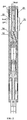
- FIGS. 1, 2 show pump module 1 of the double acting linear electrical submersible pump installable into a wellbore and driven by means of the linear drive executed as a movable part (slider) 2 of a linear submersible permanent magnet electric motor (not shown on the illustration).
- Pump module 1 contains enclosure 3 of a high pressure and of a cylindrical form with a reversing valve 4 and an inlet valve 5 .
- a pair of plungers 6 , 7 are arranged on-line inside of the enclosure, driven by the linear drive capable to force out the internal volume of the borehole fluid due to the reciprocal motion of the linear drive.
- Upper pumping plunger 6 contains delivery traveling gravity or spool valve 8 and inlet fixed gravity or spool valve 5 installed in the upper portion of its cylinder, equipped with the pusher rod, and both of said valves are closed by the oncoming flow of the borehole fluid. Also the upper plunger 6 forms a first annular cavity 9 with the pump module enclosure. Stroke of the pump module plungers in both directions is operational.
- Upper plunger 6 with integrated traveling delivery valve 8 and fixed inlet valve 5 is connected to a lower plunger 7 of a smaller diameter by means of plunger rod 10 .
- the mentioned plunger 7 is also designed as the labyrinth sealing to prevent losses of the borehole fluid and protect the linear drive from abrasive wear due to mechanical impurities effect and allows to increase the plunger stroke of the upper plunger with increasing the pump module productivity.
- Lower plunger 7 is connected to linear drive 2 , and its plunger rod 10 partially located inside of the cavity of cylinder 11 of upper plunger 6 with forming a second annular cavity 12 under its plunger rod 13 .
- said second annular cavity 12 is executed in fluid communication with the first annular cavity 9 , arranged between the pump enclosure and outer surface of the upper plunger cylinder 11 by means of common volume 14 , arranged between the pair of plungers 6 , 7 .
- Flow separator 15 of downward flaw 16 and upward flaw 17 of the borehole fluid with low-pressure channel 18 and high-pressure channel 19 respectively is installed above the cylinder of upper plunger 6 .
- the low-pressure channel is executed in fluid communication with a delivery channel 20 of borehole fluid feed from the annulus, that includes filtration zone 21 with arranged filters.
- a volume of gravitational gas separation zone 22 is greater or equal to the volume of one operating cycle of pump module 1 .
- the volume of one operating cycle is determined by the volume of fluid displaced during a single upward and downward stroke of plungers of the pumping module.
- Additional reversing valve 4 preventing a drain back of the borehole fluid from the oil well tubing is installed at an output of the pump module in a place of its connection to the oil well tubing string (not shown on the figures). Traveling valve 8 , inlet valve 5 and reversing valve 4 are executed as valves with a pusher rod 25 and are capable to be closed instantaneously by straight oncoming flow of the borehole fluid, which provides reliable operation of the section isolation valves. Consequently, it is possible to significantly simplify the design of the pump module and avoid losses of the borehole fluid as against utilization of gravity valves, used in corresponding patents.
- Borehole fluid filtration zone 23 is arranged around the lower plunger 7 for filtration of the borehole fluid, periodically filling a cavity 24 in the pump module enclosure.
- said cavity 24 is formed by the difference in radial dimensions of plunger rod 10 and linear drive 2 connected to each other.
- pair of plungers 6 and 7 are assorted in a manner for providing approximate equality of the fluid volumes pumped (displaced) during upward stroke and downward stroke.
- traveling valve 8 inlet valve 5 and reversing valve 4 are equipped with directional pusher rod 25 which contacts with locking element 26 and closed by the straight oncoming flow of the borehole fluid.
- Pump module valves ( FIG. 3 ) comprise cylindrical body 27 with locking element 26 inside of the cylindrical body, said locking element 26 is made in form of a ball.
- a motion of locking element 26 is enabled by means of pusher rod 25 with a plurality of recirculation holes 28 crossing a body of the pusher rod with an angle to a central axis of the pusher rod. Said embodiment providing that an area of increased hydraulic resistance is arranged within the pusher rod cavity 29 , which creates a hydraulic pressure necessary for a translation movement of the pusher rod.
- pump module valves comprise a cylindrical body 30 with locking element inside of the cylindrical body, which made in form of directional neck 31 with sealing cone 32 , closing by a straight oncoming flow of the borehole fluid, named locking element is made in solid-metal form and consists on parts with a variable radial cross section.
- locking element inside of the cylindrical body is made of materials with variable hardness.
- locking element 26 is made of a material, hardness of which is greater than a hardness of pusher rod 25 in preferred variant of implementation ( FIG. 3 ).
- the pusher rod 25 or directional neck 31 are made or covered with inert, corrosion-resistant and friction material.
- the method for operation of the Double Acting Linear Electrical Submersible Pump utilizing the pump module of the described design involves lowering of the said pump module together with the installation into a well and filling it with the borehole fluid with its subsequent displacement into the oil well tubing string cavity by means of reciprocal motion of plungers 6 , 7 connected to movable part of linear drive 2 , while both plunger strokes are operational.
- the borehole fluid intake from the annulus is conducted during the downward stroke ( FIG. 2 ), with upper plunger inlet valve 5 open and traveling valve 8 closed, while filling the double-volume of the cylinder 11 of the upper plunger 6 that is sufficient for one operating cycle.
- the borehole fluid is being pushed through the filtration zone 21 with installed filters and gravitational gas separation zone 22 , arranged within the borehole fluid delivery channel 20 of the pump module.
- a volume of gravitational gas separation zone 22 is executed to be greater or equal to the volume of one operating cycle of the pump module, which provides effective separation of gas particles from liquid particles and brings them out to the annulus, as shown in FIG. 2 .
- An embodiment of the claimed invention contributes to achievement of the mentioned technical result by providing simplification of the design while increasing the productivity of the pumping unit utilization by using the set of valves with absence of a complex system of channels for borehole fluid passage, which allows to regulate the fluid motion within the pump module cavity without losses even with its horizontal positioning in a well. Also the arrangement of filtration and gravitational gas separation zones provides possibility of protection from harmful effect of gas and mechanical impurities, containing in the borehole fluid.
Landscapes
- Engineering & Computer Science (AREA)
- Mechanical Engineering (AREA)
- General Engineering & Computer Science (AREA)
- Mining & Mineral Resources (AREA)
- Geology (AREA)
- Life Sciences & Earth Sciences (AREA)
- Fluid Mechanics (AREA)
- Physics & Mathematics (AREA)
- General Life Sciences & Earth Sciences (AREA)
- Geochemistry & Mineralogy (AREA)
- Environmental & Geological Engineering (AREA)
- Details Of Reciprocating Pumps (AREA)
- Reciprocating Pumps (AREA)
Abstract
Description
(d) pushing the borehole fluid through the filtration zone and the gravity gas separation zone arranged in the borehole fluid delivery channel, provided that its volume is larger or equal to the volume of one operating cycle of the pump module;
(e) displacing the borehole fluid from the annular cavity located under the upper plunger simultaneously during the downward stroke by means of its common volume arranged between the plungers and the annular cavity connected therewith, located between the pump module enclosure and the outer surface of the upper plunger cylinder, towards the high-pressure channels arranged within the separator of the descending and ascending flows of the borehole fluid installed above the upper plunger cylinder, and further through the reversing valve into the tubing string;
(f) inverting the borehole fluid flow on the reverse stroke, namely upwards with closed inlet valve and open traveling valve of the upper plunger, under influence of a pressure created within the cavity of upper plunger cylinder towards the common volume located between the pair of plungers;
(g) feeding it towards the tubing string by analogy with the downward stroke, herewith the traveling, inlet and reversing spool valves are closed by straight oncoming flow of the borehole fluid.
Claims (3)
Applications Claiming Priority (7)
| Application Number | Priority Date | Filing Date | Title |
|---|---|---|---|
| UAA201800500 | 2018-01-17 | ||
| UAU201800501 | 2018-01-18 | ||
| UAU201800501U UA125608U (en) | 2018-01-18 | 2018-01-18 | Bidirectional linear submersible pump unit |
| UAA201800500 | 2018-01-29 | ||
| RU2018110666 | 2018-03-26 | ||
| RU2018110666 | 2018-03-26 | ||
| RURU2018110666 | 2018-03-26 |
Publications (2)
| Publication Number | Publication Date |
|---|---|
| US20190219048A1 US20190219048A1 (en) | 2019-07-18 |
| US11022109B2 true US11022109B2 (en) | 2021-06-01 |
Family
ID=67213720
Family Applications (2)
| Application Number | Title | Priority Date | Filing Date |
|---|---|---|---|
| US16/051,921 Active 2039-01-22 US11022109B2 (en) | 2018-01-17 | 2018-08-01 | Double acting linear electrical submersible pump and method for its operation |
| US16/051,934 Abandoned US20190219049A1 (en) | 2018-01-17 | 2018-08-01 | Double acting linear electrical submersible pump and method for its operation |
Family Applications After (1)
| Application Number | Title | Priority Date | Filing Date |
|---|---|---|---|
| US16/051,934 Abandoned US20190219049A1 (en) | 2018-01-17 | 2018-08-01 | Double acting linear electrical submersible pump and method for its operation |
Country Status (1)
| Country | Link |
|---|---|
| US (2) | US11022109B2 (en) |
Cited By (1)
| Publication number | Priority date | Publication date | Assignee | Title |
|---|---|---|---|---|
| USD963118S1 (en) * | 2019-11-13 | 2022-09-06 | Dmytro KHACHATUROV | Valve for a linear electric submersible pump |
Families Citing this family (1)
| Publication number | Priority date | Publication date | Assignee | Title |
|---|---|---|---|---|
| CN112377154B (en) * | 2020-11-11 | 2023-02-07 | 中石化石油工程技术服务有限公司 | Automatic drainage device utilizing formation gas through magnetic reversing |
Citations (6)
| Publication number | Priority date | Publication date | Assignee | Title |
|---|---|---|---|---|
| US3981285A (en) * | 1972-08-19 | 1976-09-21 | Robert Bosch G.M.B.H. | Fuel control system for supercharged, fuel injected internal combustion engines |
| US6173768B1 (en) * | 1999-08-10 | 2001-01-16 | Halliburton Energy Services, Inc. | Method and apparatus for downhole oil/water separation during oil well pumping operations |
| US20130284423A1 (en) * | 2009-09-28 | 2013-10-31 | Guy Morrison | Downhole gas and liquid separation |
| US20150176574A1 (en) * | 2013-12-23 | 2015-06-25 | Baker Hughes Incorporated | Downhole Motor Driven Reciprocating Well Pump |
| US20160312785A1 (en) * | 2015-04-21 | 2016-10-27 | Baker Hughes Incorporated | Circulation Pump for Cooling Mechanical Face Seal of Submersible Well Pump Assembly |
| US20160369788A1 (en) * | 2015-06-17 | 2016-12-22 | Baker Hughes Incorporated | Positive Displacement Plunger Pump with Gas Escape Valve |
-
2018
- 2018-08-01 US US16/051,921 patent/US11022109B2/en active Active
- 2018-08-01 US US16/051,934 patent/US20190219049A1/en not_active Abandoned
Patent Citations (6)
| Publication number | Priority date | Publication date | Assignee | Title |
|---|---|---|---|---|
| US3981285A (en) * | 1972-08-19 | 1976-09-21 | Robert Bosch G.M.B.H. | Fuel control system for supercharged, fuel injected internal combustion engines |
| US6173768B1 (en) * | 1999-08-10 | 2001-01-16 | Halliburton Energy Services, Inc. | Method and apparatus for downhole oil/water separation during oil well pumping operations |
| US20130284423A1 (en) * | 2009-09-28 | 2013-10-31 | Guy Morrison | Downhole gas and liquid separation |
| US20150176574A1 (en) * | 2013-12-23 | 2015-06-25 | Baker Hughes Incorporated | Downhole Motor Driven Reciprocating Well Pump |
| US20160312785A1 (en) * | 2015-04-21 | 2016-10-27 | Baker Hughes Incorporated | Circulation Pump for Cooling Mechanical Face Seal of Submersible Well Pump Assembly |
| US20160369788A1 (en) * | 2015-06-17 | 2016-12-22 | Baker Hughes Incorporated | Positive Displacement Plunger Pump with Gas Escape Valve |
Cited By (1)
| Publication number | Priority date | Publication date | Assignee | Title |
|---|---|---|---|---|
| USD963118S1 (en) * | 2019-11-13 | 2022-09-06 | Dmytro KHACHATUROV | Valve for a linear electric submersible pump |
Also Published As
| Publication number | Publication date |
|---|---|
| US20190219049A1 (en) | 2019-07-18 |
| US20190219048A1 (en) | 2019-07-18 |
Similar Documents
| Publication | Publication Date | Title |
|---|---|---|
| CN110177945B (en) | Hydraulically driven double-acting positive displacement pump system for withdrawing fluids from an inclined wellbore | |
| US10995587B2 (en) | Reversing valve for hydraulic piston pump | |
| US10378532B2 (en) | Positive displacement plunger pump with gas escape valve | |
| US20100143166A1 (en) | Downhole pumping system | |
| US11634975B2 (en) | Method and apparatus for producing well fluids | |
| US11022109B2 (en) | Double acting linear electrical submersible pump and method for its operation | |
| WO2019143310A1 (en) | Double-acting linear electric submersible pump and operating method thereof | |
| CN101781979B (en) | Hydraulic driving oil extraction equipment | |
| US5651666A (en) | Deep-well fluid-extraction pump | |
| US3697199A (en) | Slide valve pump | |
| CN112576485B (en) | An oil well pump for heavy oil wells containing gas | |
| RU141547U1 (en) | DIFFERENTIAL BAR PUMP | |
| US5207726A (en) | Hydraulic pump | |
| CN103939319B (en) | Three-tube type linear dynamo oil pump | |
| US3540814A (en) | Fluid actuated down-hole pump | |
| US6364633B1 (en) | Internally ported hydraulically actuated down-hole pump | |
| RU183876U1 (en) | Bidirectional linear submersible pump unit | |
| RU2674843C1 (en) | Pump | |
| RU2351801C1 (en) | Pump installation for simultaneous-separate operation of two reservoirs of one well | |
| CN117948102A (en) | A double-acting closed-cycle liquid-driven rodless drainage and gas production system | |
| CN205779596U (en) | A kind of oil well pump and flow string | |
| US20170314546A1 (en) | Rotary Motor Driven Reciprocating Downhole Pump Assembly | |
| RU2168654C1 (en) | Oil-well sucker-rod pump | |
| CN201053305Y (en) | Straight line reciprocating oil-submersible rodless double-pump pipe column | |
| RU2519154C1 (en) | Downhole pump unit |
Legal Events
| Date | Code | Title | Description |
|---|---|---|---|
| FEPP | Fee payment procedure |
Free format text: ENTITY STATUS SET TO UNDISCOUNTED (ORIGINAL EVENT CODE: BIG.); ENTITY STATUS OF PATENT OWNER: SMALL ENTITY |
|
| FEPP | Fee payment procedure |
Free format text: ENTITY STATUS SET TO SMALL (ORIGINAL EVENT CODE: SMAL); ENTITY STATUS OF PATENT OWNER: SMALL ENTITY |
|
| STPP | Information on status: patent application and granting procedure in general |
Free format text: DOCKETED NEW CASE - READY FOR EXAMINATION |
|
| STPP | Information on status: patent application and granting procedure in general |
Free format text: RESPONSE TO NON-FINAL OFFICE ACTION ENTERED AND FORWARDED TO EXAMINER |
|
| STPP | Information on status: patent application and granting procedure in general |
Free format text: FINAL REJECTION MAILED |
|
| STPP | Information on status: patent application and granting procedure in general |
Free format text: NOTICE OF ALLOWANCE MAILED -- APPLICATION RECEIVED IN OFFICE OF PUBLICATIONS |
|
| STPP | Information on status: patent application and granting procedure in general |
Free format text: PUBLICATIONS -- ISSUE FEE PAYMENT RECEIVED |
|
| STPP | Information on status: patent application and granting procedure in general |
Free format text: PUBLICATIONS -- ISSUE FEE PAYMENT VERIFIED |
|
| STCF | Information on status: patent grant |
Free format text: PATENTED CASE |
|
| MAFP | Maintenance fee payment |
Free format text: PAYMENT OF MAINTENANCE FEE, 4TH YR, SMALL ENTITY (ORIGINAL EVENT CODE: M2551); ENTITY STATUS OF PATENT OWNER: SMALL ENTITY Year of fee payment: 4 |