US11021991B2 - Proximity vane angle measurement - Google Patents
Proximity vane angle measurement Download PDFInfo
- Publication number
- US11021991B2 US11021991B2 US16/428,051 US201916428051A US11021991B2 US 11021991 B2 US11021991 B2 US 11021991B2 US 201916428051 A US201916428051 A US 201916428051A US 11021991 B2 US11021991 B2 US 11021991B2
- Authority
- US
- United States
- Prior art keywords
- stator vane
- axis
- stator
- vane
- target surface
- Prior art date
- Legal status (The legal status is an assumption and is not a legal conclusion. Google has not performed a legal analysis and makes no representation as to the accuracy of the status listed.)
- Active, expires
Links
Images


Classifications
-
- F—MECHANICAL ENGINEERING; LIGHTING; HEATING; WEAPONS; BLASTING
- F01—MACHINES OR ENGINES IN GENERAL; ENGINE PLANTS IN GENERAL; STEAM ENGINES
- F01D—NON-POSITIVE DISPLACEMENT MACHINES OR ENGINES, e.g. STEAM TURBINES
- F01D17/00—Regulating or controlling by varying flow
- F01D17/10—Final actuators
- F01D17/12—Final actuators arranged in stator parts
- F01D17/14—Final actuators arranged in stator parts varying effective cross-sectional area of nozzles or guide conduits
- F01D17/16—Final actuators arranged in stator parts varying effective cross-sectional area of nozzles or guide conduits by means of nozzle vanes
- F01D17/162—Final actuators arranged in stator parts varying effective cross-sectional area of nozzles or guide conduits by means of nozzle vanes for axial flow, i.e. the vanes turning around axes which are essentially perpendicular to the rotor centre line
-
- F—MECHANICAL ENGINEERING; LIGHTING; HEATING; WEAPONS; BLASTING
- F01—MACHINES OR ENGINES IN GENERAL; ENGINE PLANTS IN GENERAL; STEAM ENGINES
- F01D—NON-POSITIVE DISPLACEMENT MACHINES OR ENGINES, e.g. STEAM TURBINES
- F01D17/00—Regulating or controlling by varying flow
- F01D17/02—Arrangement of sensing elements
-
- F—MECHANICAL ENGINEERING; LIGHTING; HEATING; WEAPONS; BLASTING
- F01—MACHINES OR ENGINES IN GENERAL; ENGINE PLANTS IN GENERAL; STEAM ENGINES
- F01D—NON-POSITIVE DISPLACEMENT MACHINES OR ENGINES, e.g. STEAM TURBINES
- F01D9/00—Stators
- F01D9/02—Nozzles; Nozzle boxes; Stator blades; Guide conduits, e.g. individual nozzles
- F01D9/04—Nozzles; Nozzle boxes; Stator blades; Guide conduits, e.g. individual nozzles forming ring or sector
- F01D9/041—Nozzles; Nozzle boxes; Stator blades; Guide conduits, e.g. individual nozzles forming ring or sector using blades
-
- F—MECHANICAL ENGINEERING; LIGHTING; HEATING; WEAPONS; BLASTING
- F04—POSITIVE - DISPLACEMENT MACHINES FOR LIQUIDS; PUMPS FOR LIQUIDS OR ELASTIC FLUIDS
- F04D—NON-POSITIVE-DISPLACEMENT PUMPS
- F04D27/00—Control, e.g. regulation, of pumps, pumping installations or pumping systems specially adapted for elastic fluids
- F04D27/001—Testing thereof; Determination or simulation of flow characteristics; Stall or surge detection, e.g. condition monitoring
-
- F—MECHANICAL ENGINEERING; LIGHTING; HEATING; WEAPONS; BLASTING
- F04—POSITIVE - DISPLACEMENT MACHINES FOR LIQUIDS; PUMPS FOR LIQUIDS OR ELASTIC FLUIDS
- F04D—NON-POSITIVE-DISPLACEMENT PUMPS
- F04D27/00—Control, e.g. regulation, of pumps, pumping installations or pumping systems specially adapted for elastic fluids
- F04D27/002—Control, e.g. regulation, of pumps, pumping installations or pumping systems specially adapted for elastic fluids by varying geometry within the pumps, e.g. by adjusting vanes
-
- F—MECHANICAL ENGINEERING; LIGHTING; HEATING; WEAPONS; BLASTING
- F04—POSITIVE - DISPLACEMENT MACHINES FOR LIQUIDS; PUMPS FOR LIQUIDS OR ELASTIC FLUIDS
- F04D—NON-POSITIVE-DISPLACEMENT PUMPS
- F04D27/00—Control, e.g. regulation, of pumps, pumping installations or pumping systems specially adapted for elastic fluids
- F04D27/02—Surge control
- F04D27/0246—Surge control by varying geometry within the pumps, e.g. by adjusting vanes
-
- F—MECHANICAL ENGINEERING; LIGHTING; HEATING; WEAPONS; BLASTING
- F04—POSITIVE - DISPLACEMENT MACHINES FOR LIQUIDS; PUMPS FOR LIQUIDS OR ELASTIC FLUIDS
- F04D—NON-POSITIVE-DISPLACEMENT PUMPS
- F04D29/00—Details, component parts, or accessories
- F04D29/40—Casings; Connections of working fluid
- F04D29/52—Casings; Connections of working fluid for axial pumps
- F04D29/54—Fluid-guiding means, e.g. diffusers
- F04D29/56—Fluid-guiding means, e.g. diffusers adjustable
- F04D29/563—Fluid-guiding means, e.g. diffusers adjustable specially adapted for elastic fluid pumps
-
- G—PHYSICS
- G01—MEASURING; TESTING
- G01D—MEASURING NOT SPECIALLY ADAPTED FOR A SPECIFIC VARIABLE; ARRANGEMENTS FOR MEASURING TWO OR MORE VARIABLES NOT COVERED IN A SINGLE OTHER SUBCLASS; TARIFF METERING APPARATUS; MEASURING OR TESTING NOT OTHERWISE PROVIDED FOR
- G01D5/00—Mechanical means for transferring the output of a sensing member; Means for converting the output of a sensing member to another variable where the form or nature of the sensing member does not constrain the means for converting; Transducers not specially adapted for a specific variable
- G01D5/12—Mechanical means for transferring the output of a sensing member; Means for converting the output of a sensing member to another variable where the form or nature of the sensing member does not constrain the means for converting; Transducers not specially adapted for a specific variable using electric or magnetic means
- G01D5/14—Mechanical means for transferring the output of a sensing member; Means for converting the output of a sensing member to another variable where the form or nature of the sensing member does not constrain the means for converting; Transducers not specially adapted for a specific variable using electric or magnetic means influencing the magnitude of a current or voltage
- G01D5/24—Mechanical means for transferring the output of a sensing member; Means for converting the output of a sensing member to another variable where the form or nature of the sensing member does not constrain the means for converting; Transducers not specially adapted for a specific variable using electric or magnetic means influencing the magnitude of a current or voltage by varying capacitance
- G01D5/241—Mechanical means for transferring the output of a sensing member; Means for converting the output of a sensing member to another variable where the form or nature of the sensing member does not constrain the means for converting; Transducers not specially adapted for a specific variable using electric or magnetic means influencing the magnitude of a current or voltage by varying capacitance by relative movement of capacitor electrodes
-
- G—PHYSICS
- G01—MEASURING; TESTING
- G01M—TESTING STATIC OR DYNAMIC BALANCE OF MACHINES OR STRUCTURES; TESTING OF STRUCTURES OR APPARATUS, NOT OTHERWISE PROVIDED FOR
- G01M15/00—Testing of engines
- G01M15/14—Testing gas-turbine engines or jet-propulsion engines
-
- F—MECHANICAL ENGINEERING; LIGHTING; HEATING; WEAPONS; BLASTING
- F05—INDEXING SCHEMES RELATING TO ENGINES OR PUMPS IN VARIOUS SUBCLASSES OF CLASSES F01-F04
- F05D—INDEXING SCHEME FOR ASPECTS RELATING TO NON-POSITIVE-DISPLACEMENT MACHINES OR ENGINES, GAS-TURBINES OR JET-PROPULSION PLANTS
- F05D2220/00—Application
- F05D2220/30—Application in turbines
- F05D2220/32—Application in turbines in gas turbines
-
- F—MECHANICAL ENGINEERING; LIGHTING; HEATING; WEAPONS; BLASTING
- F05—INDEXING SCHEMES RELATING TO ENGINES OR PUMPS IN VARIOUS SUBCLASSES OF CLASSES F01-F04
- F05D—INDEXING SCHEME FOR ASPECTS RELATING TO NON-POSITIVE-DISPLACEMENT MACHINES OR ENGINES, GAS-TURBINES OR JET-PROPULSION PLANTS
- F05D2240/00—Components
- F05D2240/10—Stators
- F05D2240/12—Fluid guiding means, e.g. vanes
-
- F—MECHANICAL ENGINEERING; LIGHTING; HEATING; WEAPONS; BLASTING
- F05—INDEXING SCHEMES RELATING TO ENGINES OR PUMPS IN VARIOUS SUBCLASSES OF CLASSES F01-F04
- F05D—INDEXING SCHEME FOR ASPECTS RELATING TO NON-POSITIVE-DISPLACEMENT MACHINES OR ENGINES, GAS-TURBINES OR JET-PROPULSION PLANTS
- F05D2260/00—Function
- F05D2260/70—Adjusting of angle of incidence or attack of rotating blades
- F05D2260/74—Adjusting of angle of incidence or attack of rotating blades by turning around an axis perpendicular the rotor centre line
-
- F—MECHANICAL ENGINEERING; LIGHTING; HEATING; WEAPONS; BLASTING
- F05—INDEXING SCHEMES RELATING TO ENGINES OR PUMPS IN VARIOUS SUBCLASSES OF CLASSES F01-F04
- F05D—INDEXING SCHEME FOR ASPECTS RELATING TO NON-POSITIVE-DISPLACEMENT MACHINES OR ENGINES, GAS-TURBINES OR JET-PROPULSION PLANTS
- F05D2270/00—Control
- F05D2270/80—Devices generating input signals, e.g. transducers, sensors, cameras or strain gauges
-
- G—PHYSICS
- G01—MEASURING; TESTING
- G01D—MEASURING NOT SPECIALLY ADAPTED FOR A SPECIFIC VARIABLE; ARRANGEMENTS FOR MEASURING TWO OR MORE VARIABLES NOT COVERED IN A SINGLE OTHER SUBCLASS; TARIFF METERING APPARATUS; MEASURING OR TESTING NOT OTHERWISE PROVIDED FOR
- G01D2205/00—Indexing scheme relating to details of means for transferring or converting the output of a sensing member
- G01D2205/70—Position sensors comprising a moving target with particular shapes, e.g. of soft magnetic targets
- G01D2205/77—Specific profiles
- G01D2205/776—Cam-shaped profiles
Definitions
- Exemplary embodiments of the present disclosure pertain to the art of gas turbine engines, and more particularly to variable pitch vane systems of gas turbine engines.
- Variable pitch vane systems are used to dynamically vary flow angles within a gas turbine engine throughout the engine cycle. It is imperative to precisely determine vane positional angles at any selected point throughout the cycle.
- variable vane position In the course of gas turbine engine development and operation it is imperative to have a method of monitoring variable vane position.
- the current methodology for monitoring variable pitch vane position is to employ RVDT's (Rotary Variable Differential Transformers) coaxially tied to the vane stems.
- the data provided is used to measure and calibrate variable vane arm schedules for flow control on gas turbine engines. Additionally, those variable vane arm schedules can be used to define the position of downstream stator vanes.
- the RVDT is comprised of a housing out of which protrudes a rotating stem.
- the stem of the RVDT sensor needs to be directly mounted to the rotating component, typically the variable vane stem, with the housing being held fixed.
- the connection is typically performed via either a flexible bellows or an inflexible union.
- RVDT's perform best when the housing is secured independent of rotating hardware. In all manners the RVDT sensor is in direct contact with the rotating hardware and the housing itself needs to be fixed to not rotate.
- a significant shortcoming of the RVDT is its max use temperature, 400 F, is significantly lower than the environment in which it needs to be used. As such, there is a need to provide cooling medium, typically compressed air or gaseous Nitrogen. Additionally, there is a need to design housings to encapsulate the sensor and cooling medium as well as work required to ingress and egress tubing or piping to carry the cooling medium.
- Capacitance probes function by varying output voltage based on changes in capacitance present at the sensor tip as generated by changes in linear distance to a target surface.
- the capacitance probe requires a calibration to relate the voltage change to a corresponding gap to target change. Certain characteristics of capacitance probes make them ideal for use in gas turbine engine applications including; resolution is on the order of 0.0002′′, temperature capability of ⁇ 1800 F and small form factor.
- a measurement system for determining an angular position of a component of a gas turbine engine includes one or more proximity sensors positioned at a fixed structure of the gas turbine engine and one or more sensor targets positioned at a rotatable component of the gas turbine engine.
- Each sensor target of the one or more sensor targets includes a target surface having a variable distance between the target surface and the proximity sensor with rotation of the rotatable component about a component axis of rotation.
- a measurement of distance between the proximity sensor and the target surface as measured by the proximity sensor is indicative of an angular position of the rotatable component relative to the component axis of rotation.
- the target surface is a curvilinear surface having a continuously variable or increasing radius.
- the radius is centered on the component axis of rotation.
- the one or more proximity sensors is at least two proximity sensors.
- the two or more proximity sensors are offset in a direction along the component axis of rotation.
- the two or more proximity sensors are offset circumferentially about the component axis of rotation.
- the target surface is formed integral to the rotatable component.
- a variable pitch stator vane system of a gas turbine engine includes a plurality of stator vanes, each stator vane rotatable about a stator vane axis, a synchronization ring operably connected to each stator vane of the plurality of stator vanes such that movement of the synchronization ring urges rotation of each stator vane of the plurality of stator vanes about their respective stator vane axes, and a rotational position measurement system positioned at a stator vane of the plurality of stator vanes including one or more proximity sensors positioned at a fixed structure of the gas turbine engine, and one or more sensor targets positioned at the stator vane.
- Each sensor target of the one or more sensor targets includes a target surface having a variable distance between the target surface and the proximity sensor with rotation of the stator vane about the stator vane axis.
- a measurement of distance between the proximity sensor and the target surface as measured by the proximity sensor is indicative of an angular position of the stator vane relative to the stator vane axis.
- the target surface is a curvilinear surface having a continuously variable or increasing radius.
- the radius is centered on the stator vane axis.
- the one or more proximity sensors is at least two proximity sensors.
- the at least two proximity sensors are offset in a direction along the stator vane axis.
- the at least two proximity sensors are offset circumferentially about the stator vane axis.
- each stator vane is operably connected to the synchronization ring via a vane arm configured for rotation with the stator vane about the stator vane axis.
- the target surface is formed integral to the vane arm.
- a gas turbine engine in yet another embodiment, includes a turbine section, a combustor section configured to drive rotation of the turbine, and a compressor section including a variable pitch stator vane system, including a plurality of stator vanes, each stator vane rotatable about a stator vane axis, and a synchronization ring operably connected to each stator vane of the plurality of stator vanes such that movement of the synchronization ring urges rotation of each stator vane of the plurality of stator vanes about their respective stator vane axes.
- a variable pitch stator vane system including a plurality of stator vanes, each stator vane rotatable about a stator vane axis, and a synchronization ring operably connected to each stator vane of the plurality of stator vanes such that movement of the synchronization ring urges rotation of each stator vane of the plurality of stator vanes about their respective stator vane axes.
- a rotational position measurement system is positioned at a stator vane of the plurality of stator vanes including one or more proximity sensors positioned at a fixed structure of the gas turbine engine, and one or more sensor targets positioned at the stator vane.
- Each sensor target of the one or more sensor targets included a target surface having a variable distance between the target surface and the proximity sensor with rotation of the stator vane about the stator vane axis.
- a measurement of distance between the proximity sensor and the target surface as measured by the proximity sensor is indicative of an angular position of the stator vane relative to the stator vane axis.
- the target surface is a curvilinear surface having a continuously variable or increasing radius.
- the radius is centered on the stator vane axis.
- each stator vane is operably connected to the synchronization ring via a vane arm configured for rotation with the stator vane about the stator vane axis.
- the target surface is formed integral to the vane arm.
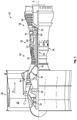
- FIG. 1 is a partial cross-sectional view of a gas turbine engine
- FIG. 2 is a schematic view of an embodiment of a variable pitch stator of a gas turbine engine
- FIG. 3 is a schematic illustration of an embodiment of a vane rotational position measurement system
- FIG. 4 is another schematic illustration of the embodiment of a vane rotational position measurement system of FIG. 3 ;
- FIG. 5 is a schematic illustration of an embodiment of a vane rotational position measurement system
- FIG. 6 is another schematic illustration of the embodiment of a vane rotational position measurement system of FIG. 5 ;
- FIG. 7 is yet another schematic illustration of an embodiment of a vane rotational position measurement system.
- FIG. 8 is a schematic illustration of still another embodiment of a vane rotational position measurement system.
- FIG. 1 schematically illustrates a gas turbine engine 20 .
- the gas turbine engine 20 is disclosed herein as a two-spool turbofan that generally incorporates a fan section 22 , a compressor section 24 , a combustor section 26 and a turbine section 28 .
- Alternative engines might include other systems or features.
- the fan section 22 drives air along a bypass flow path B in a bypass duct, while the compressor section 24 drives air along a core flow path C for compression and communication into the combustor section 26 then expansion through the turbine section 28 .
- the exemplary engine 20 generally includes a low speed spool 30 and a high speed spool 32 mounted for rotation about an engine central longitudinal axis “A” relative to an engine static structure 36 via several bearing systems 38 . It should be understood that various bearing systems 38 at various locations may alternatively or additionally be provided, and the location of bearing systems 38 may be varied as appropriate to the application.
- the low speed spool 30 generally includes an inner shaft 40 that interconnects a fan 42 , a low pressure compressor 44 and a low pressure turbine 46 .
- the inner shaft 40 is connected to the fan 42 through a speed change mechanism, which in exemplary gas turbine engine 20 is illustrated as a geared architecture 48 to drive the fan 42 at a lower speed than the low speed spool 30 .
- the high speed spool 32 includes an outer shaft 50 that interconnects a high pressure compressor 52 and high pressure turbine 54 .
- a combustor 56 is arranged in exemplary gas turbine 20 between the high pressure compressor 52 and the high pressure turbine 54 .
- An engine static structure 36 is arranged generally between the high pressure turbine 54 and the low pressure turbine 46 .
- the engine static structure 36 further supports bearing systems 38 in the turbine section 28 .
- the inner shaft 40 and the outer shaft 50 are concentric and rotate via bearing systems 38 about the engine central longitudinal axis “A” which is collinear with their longitudinal axes.
- each of the positions of the fan section 22 , compressor section 24 , combustor section 26 , turbine section 28 , and fan drive gear system 48 may be varied.
- gear system 48 may be located aft of combustor section 26 or even aft of turbine section 28
- fan section 22 may be positioned forward or aft of the location of gear system 48 .
- the engine 20 in one example is a high-bypass geared aircraft engine.
- the engine 20 bypass ratio is greater than about six (6), with an example embodiment being greater than about ten (10)
- the geared architecture 48 is an epicyclic gear train, such as a planetary gear system or other gear system, with a gear reduction ratio of greater than about 2.3
- the low pressure turbine 46 has a pressure ratio that is greater than about five.
- the engine 20 bypass ratio is greater than about ten (10:1)
- the fan diameter is significantly larger than that of the low pressure compressor 44
- the low pressure turbine 46 has a pressure ratio that is greater than about five 5:1.
- Low pressure turbine 46 pressure ratio is pressure measured prior to inlet of low pressure turbine 46 as related to the pressure at the outlet of the low pressure turbine 46 prior to an exhaust nozzle.
- the geared architecture 48 may be an epicycle gear train, such as a planetary gear system or other gear system, with a gear reduction ratio of greater than about 2.3:1. It should be understood, however, that the above parameters are only exemplary of one embodiment of a geared architecture engine and that the present disclosure is applicable to other gas turbine engines including direct drive turbofans.
- the fan section 22 of the engine 20 is designed for a particular flight condition—typically cruise at about 0.8 Mach and about 35,000 feet (10,688 meters).
- TSFC Thrust Specific Fuel Consumption
- Low fan pressure ratio is the pressure ratio across the fan blade alone, without a Fan Exit Guide Vane (“FEGV”) system.
- the low fan pressure ratio as disclosed herein according to one non-limiting embodiment is less than about 1.45.
- Low corrected fan tip speed is the actual fan tip speed in ft/sec divided by an industry standard temperature correction of [(Tram ° R)/(518.7° R)] 0.5 .
- the “Low corrected fan tip speed” as disclosed herein according to one non-limiting embodiment is less than about 1150 ft/second (350.5 m/sec).
- FIG. 2 illustrates a low compressor stator row 60 , having a variable pitch stator vane system with a plurality of stator vanes 64 .
- Each of the stator vanes 64 is connected to a synchronization ring 66 via a vane arm 68 .
- the assembly is configured such that when the synchronization ring 66 is rotated circumferentially about the engine central longitudinal axis A, each of the stator vanes 64 rotates about a vane axis 70 by, for example, an actuator 72 operably connected to the synchronization ring 66 .
- Rotation of the stator vanes 64 about their respective vane axes 70 changes a leading edge incidence angle and a trailing edge discharge angle of the flow by varying a pitch of the vanes 64 relative to the core flow C. While described herein in the context of a low pressure compressor 44 of a gas turbine engine 20 , one skilled in the art will readily appreciate that the present disclosure may be similarly applied to synchronization ring and vane arrangements in other sections of the gas turbine engine 20 , for example, the fan section 42 , the low pressure turbine 46 , the high pressure compressor 52 or the high pressure turbine 54 .
- the position measurement system 74 includes a proximity sensor 76 mounted fixedly to a static or fixed structure of the gas turbine engine 20 .
- the proximity sensor 76 is secured to a case flange 78 , or alternatively to a case boss or a bracket secured to a case or case flange 76 , or an adjacent stator vane stem of an adjacent stator vane, not stator vane 64 at which the position is measured.
- a sensor target 80 is located at the stator vane 64 and is secured and configured to rotate with the stator vane 64 about the vane axis 70 .
- the proximity sensor 76 is oriented to detect the sensor target 80 and determine a target distance 82 between the proximity sensor 76 and the sensor target 80 . More specifically, the sensor target 80 includes a target surface 84 , which is detected by proximity sensor 76 .
- the target surface 84 is configured such that the target distance 82 changes with rotation of the stator vane 64 about the vane axis 70 .
- the target distance 82 is indicative of a stator vane 64 angular position about the vane axis 70 .
- Measurements of the target distance 82 is transmitted to an engine control system 100 , a testing data acquisition system, or the like, which correlates the measured target distance 82 to a stator vane angle 102 .
- the target surface 84 is a curvilinear surface having a continuously increasing radius 86 centered at the vane axis 70 .
- the target surface 84 has a circumferential span about the vane axis of about 100 degrees. While a target surface 84 having a continuously increasing radius 86 is illustrated in the embodiment of FIG. 3 , in other embodiments the target surface 84 may have other configurations.
- the sensor target 80 is secured to a vane stem 88 of the stator vane 64 , axially between the vane arm 68 and a vane arm retention nut 90 .
- a separate sensor target is not utilized, and the target surface 84 is formed as a portion of the vane arm 68 .
- This configuration advantageously does not require the additional part to be added when it is desired to measure the stator vane 64 angle. This allows for checks during gas turbine engine 20 assembly, and real-time monitoring during operation of the gas turbine engine 20 .
- FIG. 7 Other embodiments, such as shown in FIG. 7 include multiple proximity sensors 76 and multiple sensor targets 82 and target surfaces 84 .
- a first proximity sensor 76 a and a first target surface 84 a are located outboard of a second proximity sensor 76 b and a second target surface 84 b , along the vane axis 70 direction.
- gap 82 b is a measurement of positional shift of target surface 84 b relative to sensor face 76 b .
- such an arrangement may be utilized for monitoring of vibration of the stator vanes 64 . While two proximity sensors 76 and two sensor targets 82 are described herein, one skilled in the art will readily appreciate that in some embodiments three, four or more proximity sensors 76 and sensor targets 82 may be utilized.
- a first proximity sensor 76 a is circumferentially offset about the vane axis 70 from a second proximity sensor 76 b .
- the circumferential offset is about 90 degrees.
- proximity sensor 76 and target surface 84 described herein are utilized for measuring position of the stator vanes 64 , one skilled in the art will readily appreciate that such an arrangement may be utilized for positional detection of other rotatable components, such as a compressor bleed valve, a variable nozzle position, or a synchronization ring linkage position, or any other components where it is desired to obtain one or more of angle of rotation, translation in axis or rotation, or axial shift of rotation.
- the configurations disclosed herein are more highly temperature tolerant relative to a typical RVDT arrangement, thus reducing cooling needs for measurement. Further, the measurement is non-contact, and has fewer moving parts to improve measurement accuracy and reliability. Further, the configurations have greater angle resolution per degree meaning higher angle accuracy and repeatability.
Landscapes
- Engineering & Computer Science (AREA)
- Mechanical Engineering (AREA)
- General Engineering & Computer Science (AREA)
- Physics & Mathematics (AREA)
- General Physics & Mathematics (AREA)
- Geometry (AREA)
- Power Engineering (AREA)
- Chemical & Material Sciences (AREA)
- Combustion & Propulsion (AREA)
- Structures Of Non-Positive Displacement Pumps (AREA)
Abstract
Description
Claims (17)
Priority Applications (2)
| Application Number | Priority Date | Filing Date | Title |
|---|---|---|---|
| US16/428,051 US11021991B2 (en) | 2019-05-31 | 2019-05-31 | Proximity vane angle measurement |
| EP20177224.1A EP3744951B1 (en) | 2019-05-31 | 2020-05-28 | Vane angle measurement |
Applications Claiming Priority (1)
| Application Number | Priority Date | Filing Date | Title |
|---|---|---|---|
| US16/428,051 US11021991B2 (en) | 2019-05-31 | 2019-05-31 | Proximity vane angle measurement |
Publications (2)
| Publication Number | Publication Date |
|---|---|
| US20200378270A1 US20200378270A1 (en) | 2020-12-03 |
| US11021991B2 true US11021991B2 (en) | 2021-06-01 |
Family
ID=70921815
Family Applications (1)
| Application Number | Title | Priority Date | Filing Date |
|---|---|---|---|
| US16/428,051 Active 2039-06-04 US11021991B2 (en) | 2019-05-31 | 2019-05-31 | Proximity vane angle measurement |
Country Status (2)
| Country | Link |
|---|---|
| US (1) | US11021991B2 (en) |
| EP (1) | EP3744951B1 (en) |
Cited By (1)
| Publication number | Priority date | Publication date | Assignee | Title |
|---|---|---|---|---|
| US20230323790A1 (en) * | 2022-04-12 | 2023-10-12 | Pratt & Whitney Canada Corp. | Position sensor for variable vane assembly and method for calibrating same |
Families Citing this family (2)
| Publication number | Priority date | Publication date | Assignee | Title |
|---|---|---|---|---|
| US20240426225A1 (en) * | 2023-06-26 | 2024-12-26 | Hamilton Sundstrand Corporation | Electrical actuation of variable stator vanes |
| US20250321098A1 (en) * | 2024-04-12 | 2025-10-16 | Rtx Corporation | Proximity rotational angular measurement |
Citations (13)
| Publication number | Priority date | Publication date | Assignee | Title |
|---|---|---|---|---|
| US5211539A (en) | 1991-05-13 | 1993-05-18 | Allied-Signal Inc. | Apparatus for indicating the pitch of turbofan blades |
| US5572119A (en) * | 1994-10-28 | 1996-11-05 | Barber-Colman Company | Eddy current position sensor including an insulating base having conductive surfaces for electrically connecting a coil to the lead wires |
| DE19813318A1 (en) | 1998-03-26 | 1999-09-30 | Bosch Gmbh Robert | Determining angular setting of element swivellable about axis of rotation especially throttle flap or throttle valve shaft |
| US20080273965A1 (en) * | 2007-05-01 | 2008-11-06 | United Technologies Corporation | System and method for controlling stator assemblies |
| US20090021247A1 (en) | 2006-08-28 | 2009-01-22 | Siemens Aktiengesellschaft | Device for determining the angular position of a rotatable compressor stator blade |
| US20120107094A1 (en) * | 2010-11-03 | 2012-05-03 | Hamilton Sundstrand Corporation | Shaft speed and vibration sensor apparatus |
| EP2966268A1 (en) | 2014-07-10 | 2016-01-13 | Hamilton Sundstrand Corporation | Hot environment vane angle measurement |
| US20160123718A1 (en) | 2014-10-29 | 2016-05-05 | Bridger Photonics, Inc. | Accurate chirped synthetic wavelength interferometer |
| US20160356172A1 (en) * | 2015-02-12 | 2016-12-08 | Hamilton Sundstrand Corporation | Movable vane control system |
| US20180306053A1 (en) | 2017-04-24 | 2018-10-25 | General Electric Company | Systems and Methods for Electronic Measurement of Propeller Blade Angle |
| US20180304991A1 (en) | 2017-04-24 | 2018-10-25 | Pratt & Whitney Canada Corp. | Feedback system for pitch-adjustable blades of aircraft bladed rotor |
| US10132189B2 (en) * | 2015-03-17 | 2018-11-20 | Rolls-Royce Plc | Variable vane control system |
| US20190178847A1 (en) * | 2015-08-05 | 2019-06-13 | Lovejoy Controls Corporation | Rotor deflection monitoring system |
Family Cites Families (1)
| Publication number | Priority date | Publication date | Assignee | Title |
|---|---|---|---|---|
| US9606009B2 (en) * | 2014-10-30 | 2017-03-28 | Hamilton Sundstrand Corporation | Sensor assembly for detecting position of spring-loaded target surface and method of detecting position through multiple structures |
-
2019
- 2019-05-31 US US16/428,051 patent/US11021991B2/en active Active
-
2020
- 2020-05-28 EP EP20177224.1A patent/EP3744951B1/en active Active
Patent Citations (13)
| Publication number | Priority date | Publication date | Assignee | Title |
|---|---|---|---|---|
| US5211539A (en) | 1991-05-13 | 1993-05-18 | Allied-Signal Inc. | Apparatus for indicating the pitch of turbofan blades |
| US5572119A (en) * | 1994-10-28 | 1996-11-05 | Barber-Colman Company | Eddy current position sensor including an insulating base having conductive surfaces for electrically connecting a coil to the lead wires |
| DE19813318A1 (en) | 1998-03-26 | 1999-09-30 | Bosch Gmbh Robert | Determining angular setting of element swivellable about axis of rotation especially throttle flap or throttle valve shaft |
| US20090021247A1 (en) | 2006-08-28 | 2009-01-22 | Siemens Aktiengesellschaft | Device for determining the angular position of a rotatable compressor stator blade |
| US20080273965A1 (en) * | 2007-05-01 | 2008-11-06 | United Technologies Corporation | System and method for controlling stator assemblies |
| US20120107094A1 (en) * | 2010-11-03 | 2012-05-03 | Hamilton Sundstrand Corporation | Shaft speed and vibration sensor apparatus |
| EP2966268A1 (en) | 2014-07-10 | 2016-01-13 | Hamilton Sundstrand Corporation | Hot environment vane angle measurement |
| US20160123718A1 (en) | 2014-10-29 | 2016-05-05 | Bridger Photonics, Inc. | Accurate chirped synthetic wavelength interferometer |
| US20160356172A1 (en) * | 2015-02-12 | 2016-12-08 | Hamilton Sundstrand Corporation | Movable vane control system |
| US10132189B2 (en) * | 2015-03-17 | 2018-11-20 | Rolls-Royce Plc | Variable vane control system |
| US20190178847A1 (en) * | 2015-08-05 | 2019-06-13 | Lovejoy Controls Corporation | Rotor deflection monitoring system |
| US20180306053A1 (en) | 2017-04-24 | 2018-10-25 | General Electric Company | Systems and Methods for Electronic Measurement of Propeller Blade Angle |
| US20180304991A1 (en) | 2017-04-24 | 2018-10-25 | Pratt & Whitney Canada Corp. | Feedback system for pitch-adjustable blades of aircraft bladed rotor |
Non-Patent Citations (1)
| Title |
|---|
| European Search Report for European Application No. 20177224.1; dated Aug. 24, 2020; 6 pages. |
Cited By (2)
| Publication number | Priority date | Publication date | Assignee | Title |
|---|---|---|---|---|
| US20230323790A1 (en) * | 2022-04-12 | 2023-10-12 | Pratt & Whitney Canada Corp. | Position sensor for variable vane assembly and method for calibrating same |
| US12098647B2 (en) * | 2022-04-12 | 2024-09-24 | Pratt & Whitney Canada Corp. | Position sensor for variable vane assembly and method for calibrating same |
Also Published As
| Publication number | Publication date |
|---|---|
| EP3744951B1 (en) | 2023-10-25 |
| EP3744951A1 (en) | 2020-12-02 |
| US20200378270A1 (en) | 2020-12-03 |
Similar Documents
| Publication | Publication Date | Title |
|---|---|---|
| US20200217420A1 (en) | Cantilevered hydrostatic advanced low leakage seal | |
| EP3744951B1 (en) | Vane angle measurement | |
| US11105219B2 (en) | Vane angle system accuracy improvement | |
| US10436732B2 (en) | Near full hoop electrical axial shift wear indication sensor | |
| US10480345B2 (en) | Wear indication sensor designs and methods of integration | |
| US11193593B2 (en) | Hydrostatic seal | |
| US11378187B2 (en) | Articulating cantilevered hydrostatic seal | |
| US20220282631A1 (en) | Piston ring shuttle carrier | |
| US20210062862A1 (en) | Hydrostatic seal aligned with rotor rotation | |
| US10690475B2 (en) | Encapsulated fan cap probe | |
| EP2012086A1 (en) | Displacement measurement arrangement | |
| EP4464872A1 (en) | Method for extracting rotor dynamic orbit from blade tip clearance and time of arrival measurements | |
| US10794217B2 (en) | Bleed valve system | |
| US11162365B2 (en) | Apparatus and method for inspecting an airfoil profile | |
| US10961865B2 (en) | Gas turbine engine structure with integrated actuation features | |
| US20250084770A1 (en) | Proximity measurement between seal elements of a gas turbine engine | |
| US10968767B2 (en) | Nested direct vane angle measurement shaft | |
| US12421866B2 (en) | Anti-rotation feature for instrumentation of gas turbine engine | |
| US10436728B2 (en) | Vibration induced noise suppression device | |
| US10858955B2 (en) | Gas turbine engine having a sealing member |
Legal Events
| Date | Code | Title | Description |
|---|---|---|---|
| FEPP | Fee payment procedure |
Free format text: ENTITY STATUS SET TO UNDISCOUNTED (ORIGINAL EVENT CODE: BIG.); ENTITY STATUS OF PATENT OWNER: LARGE ENTITY |
|
| AS | Assignment |
Owner name: UNITED TECHNOLOGIES CORPORATION - PRATT & WHITNEY, CONNECTICUT Free format text: ASSIGNMENT OF ASSIGNORS INTEREST;ASSIGNORS:BOUDREAU, DANIEL J.;WARREN, ELI COLE;HACKETT, BRYAN J.;REEL/FRAME:049341/0280 Effective date: 20190530 |
|
| STPP | Information on status: patent application and granting procedure in general |
Free format text: NOTICE OF ALLOWANCE MAILED -- APPLICATION RECEIVED IN OFFICE OF PUBLICATIONS |
|
| AS | Assignment |
Owner name: RAYTHEON TECHNOLOGIES CORPORATION, CONNECTICUT Free format text: CHANGE OF NAME;ASSIGNOR:UNITED TECHNOLOGIES CORPORATION;REEL/FRAME:056113/0900 Effective date: 20200403 |
|
| STPP | Information on status: patent application and granting procedure in general |
Free format text: PUBLICATIONS -- ISSUE FEE PAYMENT RECEIVED |
|
| STPP | Information on status: patent application and granting procedure in general |
Free format text: PUBLICATIONS -- ISSUE FEE PAYMENT VERIFIED |
|
| STCF | Information on status: patent grant |
Free format text: PATENTED CASE |
|
| AS | Assignment |
Owner name: RTX CORPORATION, CONNECTICUT Free format text: CHANGE OF NAME;ASSIGNOR:RAYTHEON TECHNOLOGIES CORPORATION;REEL/FRAME:064714/0001 Effective date: 20230714 |
|
| MAFP | Maintenance fee payment |
Free format text: PAYMENT OF MAINTENANCE FEE, 4TH YEAR, LARGE ENTITY (ORIGINAL EVENT CODE: M1551); ENTITY STATUS OF PATENT OWNER: LARGE ENTITY Year of fee payment: 4 |