US11020767B2 - Operator interface device for a plural component dispensing system - Google Patents
Operator interface device for a plural component dispensing system Download PDFInfo
- Publication number
- US11020767B2 US11020767B2 US15/469,018 US201715469018A US11020767B2 US 11020767 B2 US11020767 B2 US 11020767B2 US 201715469018 A US201715469018 A US 201715469018A US 11020767 B2 US11020767 B2 US 11020767B2
- Authority
- US
- United States
- Prior art keywords
- fluid component
- dispensing
- fluid
- component
- operator interface
- Prior art date
- Legal status (The legal status is an assumption and is not a legal conclusion. Google has not performed a legal analysis and makes no representation as to the accuracy of the status listed.)
- Active
Links
Images


Classifications
-
- B—PERFORMING OPERATIONS; TRANSPORTING
- B05—SPRAYING OR ATOMISING IN GENERAL; APPLYING FLUENT MATERIALS TO SURFACES, IN GENERAL
- B05C—APPARATUS FOR APPLYING FLUENT MATERIALS TO SURFACES, IN GENERAL
- B05C11/00—Component parts, details or accessories not specifically provided for in groups B05C1/00 - B05C9/00
- B05C11/10—Storage, supply or control of liquid or other fluent material; Recovery of excess liquid or other fluent material
- B05C11/1036—Means for supplying a selected one of a plurality of liquids or other fluent materials, or several in selected proportions, to the applying apparatus
-
- B—PERFORMING OPERATIONS; TRANSPORTING
- B05—SPRAYING OR ATOMISING IN GENERAL; APPLYING FLUENT MATERIALS TO SURFACES, IN GENERAL
- B05C—APPARATUS FOR APPLYING FLUENT MATERIALS TO SURFACES, IN GENERAL
- B05C5/00—Apparatus in which liquid or other fluent material is projected, poured or allowed to flow on to the surface of the work
- B05C5/02—Apparatus in which liquid or other fluent material is projected, poured or allowed to flow on to the surface of the work the liquid or other fluent material being discharged through an outlet orifice by pressure, e.g. from an outlet device in contact or almost in contact, with the work
-
- B—PERFORMING OPERATIONS; TRANSPORTING
- B29—WORKING OF PLASTICS; WORKING OF SUBSTANCES IN A PLASTIC STATE IN GENERAL
- B29B—PREPARATION OR PRETREATMENT OF THE MATERIAL TO BE SHAPED; MAKING GRANULES OR PREFORMS; RECOVERY OF PLASTICS OR OTHER CONSTITUENTS OF WASTE MATERIAL CONTAINING PLASTICS
- B29B7/00—Mixing; Kneading
- B29B7/30—Mixing; Kneading continuous, with mechanical mixing or kneading devices
- B29B7/58—Component parts, details or accessories; Auxiliary operations
- B29B7/72—Measuring, controlling or regulating
-
- G—PHYSICS
- G05—CONTROLLING; REGULATING
- G05D—SYSTEMS FOR CONTROLLING OR REGULATING NON-ELECTRIC VARIABLES
- G05D11/00—Control of flow ratio
- G05D11/02—Controlling ratio of two or more flows of fluid or fluent material
- G05D11/13—Controlling ratio of two or more flows of fluid or fluent material characterised by the use of electric means
- G05D11/131—Controlling ratio of two or more flows of fluid or fluent material characterised by the use of electric means by measuring the values related to the quantity of the individual components
- G05D11/132—Controlling ratio of two or more flows of fluid or fluent material characterised by the use of electric means by measuring the values related to the quantity of the individual components by controlling the flow of the individual components
-
- G—PHYSICS
- G08—SIGNALLING
- G08B—SIGNALLING OR CALLING SYSTEMS; ORDER TELEGRAPHS; ALARM SYSTEMS
- G08B21/00—Alarms responsive to a single specified undesired or abnormal condition and not otherwise provided for
- G08B21/18—Status alarms
-
- B—PERFORMING OPERATIONS; TRANSPORTING
- B05—SPRAYING OR ATOMISING IN GENERAL; APPLYING FLUENT MATERIALS TO SURFACES, IN GENERAL
- B05C—APPARATUS FOR APPLYING FLUENT MATERIALS TO SURFACES, IN GENERAL
- B05C11/00—Component parts, details or accessories not specifically provided for in groups B05C1/00 - B05C9/00
- B05C11/10—Storage, supply or control of liquid or other fluent material; Recovery of excess liquid or other fluent material
- B05C11/1002—Means for controlling supply, i.e. flow or pressure, of liquid or other fluent material to the applying apparatus, e.g. valves
- B05C11/1007—Means for controlling supply, i.e. flow or pressure, of liquid or other fluent material to the applying apparatus, e.g. valves responsive to condition of liquid or other fluent material
- B05C11/1013—Means for controlling supply, i.e. flow or pressure, of liquid or other fluent material to the applying apparatus, e.g. valves responsive to condition of liquid or other fluent material responsive to flow or pressure of liquid or other fluent material
-
- B—PERFORMING OPERATIONS; TRANSPORTING
- B29—WORKING OF PLASTICS; WORKING OF SUBSTANCES IN A PLASTIC STATE IN GENERAL
- B29B—PREPARATION OR PRETREATMENT OF THE MATERIAL TO BE SHAPED; MAKING GRANULES OR PREFORMS; RECOVERY OF PLASTICS OR OTHER CONSTITUENTS OF WASTE MATERIAL CONTAINING PLASTICS
- B29B7/00—Mixing; Kneading
- B29B7/74—Mixing; Kneading using other mixers or combinations of mixers, e.g. of dissimilar mixers ; Plant
- B29B7/7438—Mixing guns, i.e. hand-held mixing units having dispensing means
- B29B7/7447—Mixing guns, i.e. hand-held mixing units having dispensing means including means for feeding the components
-
- G—PHYSICS
- G08—SIGNALLING
- G08B—SIGNALLING OR CALLING SYSTEMS; ORDER TELEGRAPHS; ALARM SYSTEMS
- G08B6/00—Tactile signalling systems, e.g. personal calling systems
Definitions
- This disclosure relates generally to plural component dispensing systems, and more particularly to operator interface devices for the plural component dispensing systems.
- Multiple component applicators often receive separate inert fluid components that are mixed and dispensed as an activated compound.
- multiple component applicators are used to dispense epoxies and polyurethanes that solidify after mixing of a resin component and an activating material, which are individually inert.
- the component materials are mixed at a predetermined ratio.
- a system controller device is often connected to control operation of the system to produce the predetermined ratio at a dispensing device and to provide operator feedback information corresponding to an operational state of the system.
- the system controller can issue an alert at a display device and/or speaker device of the controller in response to determining that a monitored ratio of the individual components delivered to the dispensing device deviates from the predetermined ratio.
- the system controller often provides an interface to control operation of the system via received operator input via buttons, switches, or other input devices of the controller.
- An operator of the dispensing device may be physically remote from the controller device while applying the activated compound. For instance, an operator can be tens or hundreds of feet from the controller device while operating the dispensing device, possibly in a noisy environment, and out of direct line-of-sight of the controller. In such examples, the operator may be unable to see (or hear) alerts generated by the system controller. Moreover, in such examples, the operator must redirect his or her attention from the dispensing point and often must physically move from the dispensing point to check the system's status and provide input to the controller to acknowledge the alert and/or change the operational state of the controller.
- a plural component dispensing system includes a dispensing device configured to receive a first fluid component and a second fluid component, a first fluid component source, a second fluid component source, a system controller, and an operator interface device.
- the first fluid component source is connected to the dispensing device to deliver the first fluid component to the dispensing device.
- the second fluid component source is connected to the dispensing device to deliver the second fluid component to the dispensing device.
- the system controller is connected to regulate operation of the first fluid component source and the second fluid component source to produce a target ratio of the first fluid component and the second fluid component at the dispensing device.
- the operator interface device is remote from and operatively connected to the system controller. The operator interface device is configured to output system state information received from the system controller and to receive operator input to control an operational state of the system controller.
- an operator interface device for a plural component dispensing system includes at least one input device, at least one output device, one or more processors, and computer-readable memory.
- the computer-readable memory is encoded with instructions that, when executed by the one or more processors, cause the operator interface device to: output, via the at least one output device, system state information received from a system controller of the plural component dispensing system that is remote from the operator interface device; receive, via the at least one input device, operator input to control an operational state of the system controller; and transmit the operator input to the system controller.
- FIG. 1 is a schematic block diagram of a two component fluid dispensing system including an operator interface device that is remote from and operatively connected to a system controller.
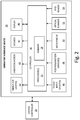
- FIG. 2 is a schematic block diagram showing further details of the operator interface device of FIG. 1 .
- an operator interface device of a plural component dispensing system is remote from and operatively connected to a system controller that controls operation of the plural component dispensing system.
- the operator interface device outputs system state information received from the system controller, such as alert notifications, system state information corresponding to a ratio of fluid components delivered to a dispensing device, or other system state information.
- the operator interface device is configured to receive operator input to control an operational state of the system controller, such as via touch input (e.g., button actuation, switch actuation, or other touch input), motion input (e.g., via sensed motion of the operator interface device corresponding to a defined motion gesture), orientation input (e.g., via sensed physical orientation of the operator interface device), or other operator input to acknowledge alerts or otherwise control an operational state of the system controller.
- the operator interface device can be integral to or attached to a dispensing device that delivers an activated compound formed from the multiple fluid components.
- the operator interface device can be wearable by the operator, such as via a lanyard around the operator's neck, wearable around the operator's wrist, or otherwise wearable by the operator.
- a system implementing techniques of this disclosure provides output to an operator of the dispensing device and enables operator input at a dispensing location that may be remote from the system controller.
- techniques of this disclosure help to increase operator awareness of the system operational state and enable operator feedback at locations that may be remote from the system controller.
- FIG. 1 is a schematic block diagram of fluid dispensing system 10 .
- fluid dispensing system 10 includes fluid component A source 12 , fluid component B source 14 , fluid component A delivery system 16 , fluid component B delivery system 18 , fluid component A flow meter 20 , fluid component B flow meter 22 , dispensing device 24 , operator interface device 26 , system controller 28 , and database 30 .
- Dispensing device 24 includes applicator 32 and mixer 34 .
- Fluid component A source 12 and fluid component B source 14 each store individually-inert fluid components that, when mixed at dispensing device 24 (e.g., at mixer 34 ), chemically react to form an activated material, such as a quick-cure polyurethane foam, an epoxy, or other activated material that is delivered from dispensing device 24 .
- fluid component A stored at fluid component A source 12 can be a catalyst fluid component and fluid component B stored at fluid component B source 14 can be a base material that, when mixed, chemically react to form the activated material.
- Each of fluid component A delivery system 16 and fluid component B delivery system 18 can be pumps (e.g., positive displacement pumps), compressed gas delivery systems, or other delivery systems configured to cause fluid component A source 12 to discharge fluid component A (i.e., via fluid component A delivery system 16 ) and fluid component B source 14 to discharge fluid component B (i.e., via fluid component B delivery system 18 ).
- pumps e.g., positive displacement pumps
- compressed gas delivery systems or other delivery systems configured to cause fluid component A source 12 to discharge fluid component A (i.e., via fluid component A delivery system 16 ) and fluid component B source 14 to discharge fluid component B (i.e., via fluid component B delivery system 18 ).
- each of fluid component A source 12 and fluid component B source 14 are hydraulically connected to dispensing device 24 .
- Fluid component A flow meter 20 is located between fluid component A source 12 and dispensing device 24 to measure a volumetric flow rate of fluid component A discharged from fluid component A source 12 to dispensing device 24 .
- Fluid component B flow meter 22 is located between fluid component B source 14 and dispensing device 24 to measure a volumetric flow rate of fluid component B discharged from fluid component B source 18 to dispensing device 24 .
- Each of fluid component A flow meter 20 and fluid component B flow meter 22 can be a positive displacement meter (e.g., gear meter), mass flow meter, or other type of flow meter.
- Fluid component A flow meter 20 and fluid component B flow meter 22 can be a same or different type of flow meter.
- each of fluid component A flow meter 20 and fluid component B flow meter 22 can be any type of flow meter configured to measure a volumetric flow rate of fluid component passing through the respective flow meter and transmit an indication of the sensed volumetric flow rate to system controller 28 .
- Dispensing device 24 includes applicator 32 and mixer 34 .
- Dispensing device 24 can be, e.g., a dispensing gun configured to receive the individually-inert fluid component A and fluid component B and deliver an activated component after mixing of the two components at mixer 34 . That is, applicator 32 receives each of fluid component A and fluid component B and provides the two individual components to mixer 34 , which mixes the two components during delivery. Accordingly, mixing of fluid component A and fluid component B is delayed until delivery of the components through mixer 34 and release of the activated material from dispensing device 24 .
- System controller 28 includes one or more processors and computer-readable memory encoded with instructions that, when executed by the one or more processors, cause system controller 28 to operate in accordance with techniques described herein.
- the one or more processors include any one or more of a microprocessor, a digital signal processor (DSP), an application specific integrated circuit (ASIC), a field-programmable gate array (FPGA), or other equivalent discrete or integrated logic circuitry.
- Computer-readable memory of system controller 28 can be configured to store information within system controller 28 during operation.
- the computer-readable memory can be described, in some examples, as computer-readable storage media.
- a computer-readable storage medium can include a non-transitory medium.
- Non-transitory can indicate that the storage medium is not embodied in a carrier wave or a propagated signal.
- a non-transitory storage medium can store data that can, over time, change (e.g., in RAM or cache).
- Computer-readable memory of system controller 28 can include volatile and non-volatile memories. Examples of volatile memories can include random access memories (RAM), dynamic random access memories (DRAM), static random access memories (SRAM), and other forms of volatile memories. Examples of non-volatile memories can include magnetic hard discs, optical discs, floppy discs, flash memories, or forms of electrically programmable memories (EPROM) or electrically erasable and programmable (EEPROM) memories.
- RAM random access memories
- DRAM dynamic random access memories
- SRAM static random access memories
- Examples of non-volatile memories can include magnetic hard discs, optical discs, floppy discs, flash memories, or forms of electrically programmable memories (EPROM) or electrically erasable and programmable (EEPROM)
- System controller 28 includes user interface components including one or more input devices (e.g., a keyboard, buttons, mouse, microphone, or other input devices) configured to receive input from a user and one or more output devices (e.g., a display device, indicator lights, or other output devices) configured to present information to a user.
- system controller 28 includes a touch-sensitive display configured to receive user input in the form of gestures (e.g., touch gestures, swipe gestures, pinch gestures, or other gestures) and to display information to the user.
- system controller 28 is communicatively coupled with database 30 .
- Database 30 can be a hierarchical database, a relational database, a multi-dimensional database, or other type of database.
- System controller 28 utilizes database 30 to store system state information in association with product identification information and/or operator identification information, as is further described below. Though illustrated as including a single database, in other examples, database 30 can be implemented as multiple databases or other data retrieval and/or archival data structures.
- system controller 28 can store and/or implement database 30 , such as at computer-readable memory of system controller 28 .
- System controller 28 is electrically and/or communicatively coupled with each of fluid component A flow meter 20 and fluid component B flow meter 22 to receive volumetric flow rates sensed by each of fluid component A flow meter 20 and fluid component B flow meter 22 .
- System controller 28 is further connected (e.g., electrically and/or communicatively connected) to each of fluid component A delivery system 16 and fluid component B delivery system 18 to control operation of fluid component A delivery system 16 and fluid component B delivery system 18 to produce a target ratio of fluid component A and fluid component B delivered to dispensing device 24 .
- system controller 28 can transmit control commands in the form of voltage control commands, electrical current control commands, or other control commands to cause fluid component A delivery system 16 and fluid component B delivery system 18 to regulate the respective fluid flow discharge rates of fluid component A and fluid component B to produce a target ratio (i.e., a target mix ratio) of fluid component A and fluid component B delivered to dispensing device 24 .
- System controller 28 can store the target ratio and/or receive the target ratio via a user interface of system controller 28 (e.g., via user input).
- System controller 28 determines a ratio of fluid component A to fluid component B delivered to dispensing device 24 as the ratio of the volumetric flow rate sensed by fluid component A flow meter 20 to the volumetric flow rate sensed by fluid component B flow meter 22 . Based on the determined ratio of the volumetric flow rates, system controller 28 controls operation of fluid component A delivery system 16 and fluid component B delivery system 18 to regulate the respective fluid discharge rates to produce the target mix ratio.
- system controller 28 can implement a proportional-integral-derivative or other control algorithm to cause fluid component A delivery system 16 to increase a discharge rate of fluid component A and/or to cause fluid component B delivery system 18 to decrease a discharge rate of fluid component B in response to determining that the ratio of the sensed volumetric flow rate received from fluid component A flow meter 20 to the sensed volumetric flow rate received from fluid component B flow meter 22 is less than the target ratio of fluid component A to fluid component B.
- System controller 28 can cause fluid component A delivery system 16 to decrease a discharge rate of fluid component A and/or cause fluid component B delivery system 18 to increase a discharge rate of fluid component B in response to determining that the ratio of the sensed volumetric flow rate received from fluid component A flow meter 20 to the sensed volumetric flow rate received from fluid component B flow meter 22 is greater than the target ratio of fluid component A to fluid component B. As such, system controller 28 can automatically control operation of fluid component A delivery system 16 and/or fluid component B delivery system 18 to produce the target mix ratio of fluid component A and fluid component B delivered to dispensing device 24 .
- system controller 28 is operatively connected (e.g., electrically and/or communicatively connected) to operator interface device 26 .
- the operative connection can be a wired connection, a wireless connection, or both.
- Operator interface device 26 is configured to output system state information received from system controller 28 corresponding to an operational state of fluid component dispensing system 10 .
- operator interface device 26 is configured to receive operator input to control an operational state of system controller 28 , as is further described below.
- system state information received by operator interface device 26 from system controller 28 include, but are not limited to, an indication of whether a ratio of fluid component A and fluid component B delivered to dispensing device 24 (e.g., determined by system controller 28 via sensed volumetric flow rates received from fluid component A flow meter 20 and fluid component B flow meter 22 ) deviates from the target ratio of fluid component A and fluid component B, an indication of an operational mode of system controller 28 , and an indication of an alert condition of fluid dispensing system 10 .
- Indications of the operational mode of system controller 28 can include, e.g., an indication of a fluid dispensing operational mode in which both fluid component A and fluid component B are delivered to dispensing device 24 , an indication of a purge mode in which only one of fluid component A and fluid component B is delivered to dispensing device 24 , an indication of a standby mode in which system controller 28 refrains from causing either of fluid component A or fluid component B to be discharged, or other operational modes.
- Indications of the alert condition can include, for example, an indication that the ratio of fluid component A and fluid component B delivered to dispensing device 24 deviates from the target ratio, an indication that a remaining volume of fluid component A within fluid component A source 12 and/or a remaining volume of fluid component B within fluid component B source 14 is less than a threshold volume, or other indications of alert conditions.
- Examples of operator input received by operator interface device 26 and transmitted to system controller 28 to control an operational state of system controller 28 can include, e.g., touch input received via actuation of buttons, switches, or other touch input devices of operator interface device 26 , motion input sensed by one or motion sensors of operator interface device 26 (e.g., accelerometers, rate gyroscopes, or other motion sensors), orientation input sensed by one or more orientation sensors of operator interface device 26 (e.g., accelerometers or other orientation sensors), voice or other audible input sensed by a microphone of operator interface device 26 , product identification data retrieved by an optical scanner and/or RFID reader of operator interface device 26 , or other types of operator input.
- touch input received via actuation of buttons, switches, or other touch input devices of operator interface device 26 can include, e.g., touch input received via actuation of buttons, switches, or other touch input devices of operator interface device 26 , motion input sensed by one or motion sensors of operator interface device 26 (e.g., accelerometers,
- Operator interface device 26 can be attached to or integrally formed with dispensing device 24 .
- operator interface device 26 is integrally formed within an interior of dispensing device 24 , such as within a handle 60 or other housing of dispensing device 24 .
- operator interface device 26 is configured to be attached to an exterior of dispensing device 24 , such as via bolt, screw, clip, or other fastening devices.
- operator interface device 26 is configured to be wearable by the operator.
- operator interface device 26 can be configured to be worn around the operator's neck via a lanyard, around the operator's wrist (e.g., as a watch), or otherwise worn by the operator.
- operator interface device 26 is configured to be attached to, integrally formed with, or otherwise collocated with dispensing device 24 during operation of dispensing device 24 to deliver the activated material at, e.g., a worksite.
- Hydraulic connections between dispensing device 24 and fluid component A source 12 and fluid component B source 14 enable operation of dispensing device 24 at a dispensing location that can be, e.g., tens of feet, hundreds of feet, or other distances from system controller 28 to deliver the activated material.
- Operator interface device 26 configured to be collocated with dispensing device 24 during operation, enables the operator to receive feedback regarding an operating state of the system as well as to provide input to control an operational state of the controller from the dispensing location without requiring the operator to physically move to the controller to check the system status or provide operating inputs.
- a system implementing techniques of this disclosure enhances operator awareness and increases efficiency of operator inputs to control the fluid dispensing system.
- FIG. 2 is a schematic block diagram showing further details of operator interface device 26 .
- the example of FIG. 2 will be described below within the context of fluid dispensing system 10 of FIG. 1 .
- operator interface device 26 includes controller 36 , one or more indicator lights 38 , vibration motor 40 , speaker device 42 , display device 44 , one or more touch input devices 46 , one or more position and motion sensors 48 , microphone 50 , optical scanner 52 , and radio-frequency identification (RFID) reader 54 .
- Controller 36 includes one or more processors 56 and computer-readable memory 58 .
- operator interface device 26 is operatively coupled with system controller 28 via one or more wired or wireless communication networks, or both.
- Controller 36 receives system state information from system controller 28 via the wired and/or wireless connection and outputs an indication of the system state information via any one or more of indicator lights 38 , vibration motor 40 , speaker device 42 , and display device 44 .
- Controller 36 receives operator input via any one or more of display device 44 (e.g., a touch-sensitive and/or presence-sensitive display device), touch input devices 46 , position and motion sensors 48 , microphone 50 , optical scanner 52 , and RFID reader 54 .
- Controller 36 transmits an indication of the received operator input to system controller 28 via the wired and/or wireless connection to control an operational state of system controller 28 , as is further described below.
- Processors 56 and computer-readable memory 58 of controller 36 can be substantially similar to processors and computer-readable memory of system controller 28 . That is, processors 56 can include any one or more of a microprocessor, a digital signal processor (DSP), an application specific integrated circuit (ASIC), a field-programmable gate array (FPGA), or other equivalent discrete or integrated logic circuitry. Computer-readable memory 58 can include volatile and/or non-volatile memory encoded with instructions that, when executed by processors 56 , cause controller 36 to operate in accordance with techniques described herein.
- DSP digital signal processor
- ASIC application specific integrated circuit
- FPGA field-programmable gate array
- Indicator lights 38 can include any one or more light emitting diodes (LEDs), indicator lamps, or other types of indicator lights.
- Controller 36 controls an illumination state of one or more of indicator lights 38 to indicate system state information received from system controller 28 . For instance, in examples where system state information received from system controller 28 includes an indication of whether a ratio of fluid component A and fluid component B delivered to dispensing device 24 deviates from the target ratio, controller 36 can control an illumination state of indicator lights 38 to indicate whether the ratio of fluid component A and fluid component B deviates from the target ratio.
- controller 36 can illuminate one or more of indicator lights 38 in response to receiving system state information from system controller 28 indicating that the ratio of fluid component A and fluid component B delivered to dispensing device 24 does not deviate from the target ratio. Controller 36 can cause the one or more indicator lights 38 to operate in a non-illuminated state in response to receiving the system state information indicating that the ratio of fluid component A and fluid component B delivered to dispensing device 24 deviates from the target ratio.
- controller 36 can cause the one or more of indicator lights 38 to operate in the non-illuminated state in response to receiving system state information from system controller 28 indicating that the ratio of fluid component A and fluid component B delivered to dispensing device 24 does not deviate from the target ratio, and can cause the one or more of indicator lights 38 to operate in the illuminated state in response to receiving the system state information indicating that the ratio of fluid component A and fluid component B delivered to dispensing device 24 deviates from the target ratio.
- controller 36 can cause a first one of indicator lights 38 (e.g., a green indicator light) to illuminate in response to receiving the system state information indicating that the ratio of fluid component A and fluid component B delivered to dispensing device 24 does not deviate from the target ratio, and can cause a second one of indicator lights 38 (e.g., a red indicator light) to illuminate in response to receiving the system state information indicating that the ratio of fluid component A and fluid component B delivered to dispensing device 24 deviates from the target ratio.
- controller 36 can control an illumination state of any one or more of indicator lights 38 to indicate system state information received from system controller 28 , such as to indicate whether a ratio of fluid component A and fluid component B delivered to dispensing device 24 deviates from a target ratio.
- Vibration motor 40 can be an electric motor or other type of motor that, when actuated, causes vibration motor 40 to vibrate to provide haptic vibration feedback that can be felt by an operator in contact with operator interface device 26 .
- vibration motor 40 can be an electric motor having an unbalanced mass on a driveshaft that, when actuated, causes vibration motor 40 (and hence operator interface device 26 ) to vibrate.
- Controller 36 actuates vibration motor 40 to provide haptic vibration feedback indicating system state information received from system controller 28 .
- controller 36 can actuate vibration motor 40 to provide the haptic vibration feedback in response to receiving system state information indicating an alert condition, such as an alert condition corresponding to a ratio of fluid component A and fluid component B delivered to dispensing device 24 that deviates from the target ratio, an alert condition corresponding to a volume of fluid component A within fluid component A source 12 and/or a volume of fluid component B within fluid component B source 14 that is less than a threshold volume, or other type of alert condition.
- an alert condition such as an alert condition corresponding to a ratio of fluid component A and fluid component B delivered to dispensing device 24 that deviates from the target ratio
- controller 36 can actuate vibration motor 40 to provide haptic vibration feedback configured to identify the alert condition, such as a first defined pattern of vibration (e.g., one vibration) indicating a first alert condition, a second defined pattern of vibration (e.g., two or more vibrations in sequence) indicating a second alert condition, or other patterns of vibrations.
- controller 36 can actuate vibration motor 40 to provide haptic vibration feedback to an operator to notify the operator of an alert condition, a change in a system operational state, and/or to identify an alert condition or other operational state of system controller 28 .
- Controller 36 utilizes speaker 42 to output audible tones indicating system state information received from system controller 28 .
- controller 36 can cause speaker 42 to output a single tone, a multi-tone output, a sequence of tones, a buzzer, voice outputs, or other audible indications of system state information and/or alert conditions.
- Display device 44 can be a liquid crystal display (LCD), alphanumeric display, or other type of display configured to present content to an operator.
- display device 44 can include a touch-sensitive and/or presence-sensitive interface to enable operator input in the form of touch gestures (e.g., tap gestures, swipe gestures, pinch gestures, or other gestures).
- Controller 36 presents system state information received from system controller 28 at display device 44 .
- controller 36 can cause display device 44 to display a current operational state (e.g., mode of operation), an indication of an alert condition, an indication of a type of alert, a current ratio of fluid component A and fluid component B delivered to dispensing device 24 , the target ratio of fluid component A and fluid component B, or other system state information.
- a current operational state e.g., mode of operation
- controller 36 can receive operator input to, e.g., acknowledge an alert condition and/or change an operation state of system controller 28 via gesture input received at display device 44 .
- controller 36 receives input from any one or more of touch input devices 46 , position and motion sensors 48 , microphone 50 , optical scanner 52 , and RFID reader 54 .
- Touch input devices 46 can include buttons, switches, or other types of touch-activated input devices to enable operator input to acknowledge an alert condition or otherwise control an operational state of system controller 36 .
- touch input devices 46 can enable operator input to change system operating modes, such as from a dispensing mode in which fluid component A and fluid component B are delivered to dispensing device 24 to a standby mode in which fluid component A and fluid component B are not delivered to dispensing device 24 .
- Touch input devices 46 in some examples, can enable operator input to change system parameters, such as a flow rate of one or more of fluid component A and fluid component B delivered to dispensing device 24 .
- Position and motion sensors 48 can include, e.g., any one or more accelerometers and/or rate gyroscopes configured to sense relative motion and/or orientation of operator interface device 26 .
- Controller 36 can, in certain examples, compare relative motion sensed by the accelerometers and/or rate gyroscopes to motion corresponding to a predetermined motion gesture (e.g., a shaking motion gesture, an impact motion gesture, or other motion gesture) to determine whether the sensed motion corresponds to operator input to control an operational state of system controller 28 .
- a predetermined motion gesture e.g., a shaking motion gesture, an impact motion gesture, or other motion gesture
- controller 36 can compare motion sensed by position and motion sensors 48 to a predetermined motion gesture corresponding to a shaking motion gesture (e.g., shaking of operator interface device 26 ), and can determine that the shaking motion corresponds to operator input to acknowledge an alert, such as an alert corresponding to a ratio of fluid component A and fluid component B delivered to dispensing device 24 that deviates from the target ratio.
- controller 36 can transmit an indication of the motion gesture to acknowledge the alert condition to system controller 28 , which controls an operational state based on the received acknowledgement (e.g., by clearing the alert condition, continuing to operate with the alert condition, resuming a fluid dispensing operational mode in response to receiving the acknowledgement, or otherwise controlling the operational state based on the received acknowledgement).
- controller 36 can compare the relative motion sensed by the accelerometers and/or rate gyroscopes to predefined motion gestures to change the operational state of system controller 28 .
- a first predefined motion gesture can correspond to operator input to initiate a fluid dispensing operational mode of system controller 28 in which system controller 28 causes delivery of fluid component A and fluid component B to dispensing device 24 .
- a second predefined motion gesture can correspond to operator input to initiate a standby operational mode of system controller 28 in which system controller 28 ceases to cause delivery of fluid component A and fluid component B to dispensing device 24 .
- sensed motion of operator interface device 26 corresponding to predefined motion gestures can enable control of an operational mode of system controller 28 via the predefined motion gestures.
- controller 36 can compare motion sensed by the accelerometers and/or rate gyroscopes to motion corresponding to any one or more predetermined motion gestures associated with defined operator input to acknowledge an alert condition or otherwise control an operational state of system controller 28 .
- position and motion sensors 48 can include one or more orientation sensors, such as a plurality of accelerometers (e.g., three accelerometers), each aligned along one of a plurality of mutually-orthogonal axes.
- Controller 36 can determine an orientation of operator interface device 26 based on orientation sensed via the plurality of accelerometers. Controller 36 can determine whether the sensed orientation corresponds to operator input to control an operational state of system controller 28 . For instance, controller 36 can determine whether the sensed orientation corresponds to an orientation of, e.g., a nozzle of dispensing device 24 that is within a threshold angle (e.g., within ten degrees) from a vertical orientation with the nozzle pointed toward the ground.
- a threshold angle e.g., within ten degrees
- Such vertical orientation with the nozzle pointed toward the ground can correspond to operator input of placing the nozzle of dispensing device 24 within a bucket or other container to initiate, e.g., a purge mode of operation in which only one of fluid component A and fluid component B is delivered to dispensing device 24 to purge dispensing device 24 of the other fluid component.
- a purge mode of operation in which only one of fluid component A and fluid component B is delivered to dispensing device 24 to purge dispensing device 24 of the other fluid component.
- the purge mode can initiate delivery of only fluid component B (i.e., the base component in this example) to dispensing device 24 to purge dispensing device 24 of residual fluid component A (i.e., catalyst component in this example).
- Controller 36 in response to identifying that the orientation of operator interface device 26 corresponds to the operator input orientation to initiate (or enable) the base purge mode, can transmit an indication of the orientation to system controller 28 .
- System controller 28 in response, can initiate (or enable) the base purge mode.
- controller 36 can compare orientation information sensed by orientation sensors (e.g., accelerometers) of operator interface device 26 to defined operator orientation input to enable operator input to control an operational state of system controller 28 via orientation of operator interface device 26 .
- orientation sensors e.g., accelerometers
- position and motion sensors 48 can include a proximity sensor that senses proximity of the sensor to another object. For instance, such as when operator interface device 26 is disposed proximate a nozzle of dispensing device 24 , controller 36 can transmit to system controller 28 an indication of whether the proximity sensor senses proximity to an object (e.g., a product to which activated compound is to be applied). System controller 28 can enable delivery of fluid component A and fluid component B to dispensing device 24 in response to an indication received from operator interface device 26 corresponding to sensed proximity to an object, and can disable delivery of the fluid components in response to an indication received from operator interface device 26 indicating that proximity to an object is not sensed.
- an object e.g., a product to which activated compound is to be applied.
- System controller 28 can enable delivery of fluid component A and fluid component B to dispensing device 24 in response to an indication received from operator interface device 26 corresponding to sensed proximity to an object, and can disable delivery of the fluid components in response to an indication received from operator interface device 26 indicating that proximity to an
- system controller 28 can enable dispensing of the activated compound from dispensing device 24 when operator interface device 26 (and hence the nozzle in this example) is close to an object, and can disable dispensing of the activated compound when operator interface device 26 (and the nozzle) is not close to an object.
- Controller 36 receives audible operator input via microphone 50 .
- audible input can include, e.g., voice input commands to acknowledge an alert condition or otherwise control an operational state of system controller 28 .
- controller 36 can implement one or more voice recognition algorithms to compare audible inputs received via microphone 50 to speech patterns corresponding to define operator input commands.
- controller 36 can transmit an indication of the identified input command to system controller 28 , which controls an operational state according to the received command.
- Optical scanner 52 can include any optical input device (e.g., a camera, a laser-based scanner, or other optical input device) that captures machine-readable encoded information, such as a barcode, a matrix barcode (e.g., QR code), or other machine-readable encoded information and translates the encoded information to digital form.
- RFID reader 54 includes a radio-frequency antenna that sends and/or receives power, data, and/or commands to retrieve information from RFID tags remote from RFID reader 54 .
- Controller 36 utilizes optical scanner 52 and/or RFID reader 54 to retrieve information corresponding to products to which activated compound is to be applied using dispensing device 24 .
- a product to which activated compound is to be applied e.g., a window to which activated epoxy is to be applied
- Controller 36 can retrieve the product identification information via optical scanner 52 and/or RFID reader 54 , and can transmit the product identification information to system controller 28 .
- System controller 28 can store the product identification information within database 30 in association with system state information of fluid dispensing system 10 during application of the activated compound to the product via dispensing device 24 .
- system state information stored in association with the product identification information can include, e.g., a time and/or date of application of the activated compound, a ratio of fluid component A and fluid component B delivered to dispensing device 24 during application, a volume of one or more of fluid component A and fluid component B delivered to dispensing device 24 during application, an indication of whether alert conditions were triggered during the application, or other system state information.
- Such stored information can be later retrieved to assess the qualities of activated compound applied to a particular product, as well as the operational state of fluid dispensing system 10 during application.
- controller 36 transmits identification information retrieved from an RFID tag via RFID reader 54 to system controller 28 .
- System controller 28 can, in certain examples, control an operational state of system controller 28 based on the received identification information corresponding to the RFID tag. For instance, system controller 28 can enable operation of dispensing device 24 to apply the activated compound by delivering fluid component A and fluid component B to dispensing device 24 in response to receiving the identification information retrieved from the RFID tag, and can disable operation of dispensing device 24 to apply the activated compound by ceasing to deliver fluid component A and fluid component B to dispensing device 24 when the identification information is not received.
- system controller 28 can enable operation of dispensing device 24 to apply the activated compound when, for example, operator interface device 26 is near to the RFID tag including the identification information (e.g., located at a designated work area), and can disable operation of dispensing device 24 when operator interface device 26 is not near to the RFID tag.
- an RFID tag including unique operator identification information can be worn by or otherwise collocated with the operator.
- controller 36 can transmit, to system controller 28 , the unique operator identification information retrieved from the RFID tag by RFID reader 54 .
- System controller 28 can store system state information in association with the unique operator identification information at, e.g., database 30 .
- Stored system state information can include, e.g., a ratio of fluid component A and fluid component B delivered to dispensing device 24 during application, a volume of one or more of fluid component A and fluid component B delivered to dispensing device 24 during application, an indication of whether alert conditions were triggered during the application, or other system state information.
- system controller 28 can store information corresponding to operator usage of fluid dispensing system 10 that is unique to a particular operator and which can be later retrieved for, e.g., operations planning feedback or other activities.
- operator interface device 26 can provide output to an operator of dispensing device 24 and enable operator input at a dispensing location that may be remote from system controller 28 .
- techniques described herein can increase operator awareness of the operational state of fluid dispensing system 10 and enable operator input to control the operational state at locations that may be remote from system controller 28 .
Abstract
Description
Claims (20)
Priority Applications (2)
| Application Number | Priority Date | Filing Date | Title |
|---|---|---|---|
| US15/469,018 US11020767B2 (en) | 2016-03-28 | 2017-03-24 | Operator interface device for a plural component dispensing system |
| US17/322,041 US11815919B2 (en) | 2013-02-11 | 2021-05-17 | Operator interface device and distributed control for fluid dispensing systems |
Applications Claiming Priority (2)
| Application Number | Priority Date | Filing Date | Title |
|---|---|---|---|
| US201662313929P | 2016-03-28 | 2016-03-28 | |
| US15/469,018 US11020767B2 (en) | 2016-03-28 | 2017-03-24 | Operator interface device for a plural component dispensing system |
Related Child Applications (3)
| Application Number | Title | Priority Date | Filing Date |
|---|---|---|---|
| US14/766,712 Continuation-In-Part US9939822B2 (en) | 2013-02-11 | 2014-02-11 | Remote monitoring for fluid applicator system |
| PCT/US2014/015698 Continuation-In-Part WO2014124416A1 (en) | 2013-02-11 | 2014-02-11 | Remote monitoring for fluid applicator system |
| US17/322,041 Continuation-In-Part US11815919B2 (en) | 2013-02-11 | 2021-05-17 | Operator interface device and distributed control for fluid dispensing systems |
Publications (2)
| Publication Number | Publication Date |
|---|---|
| US20170274413A1 US20170274413A1 (en) | 2017-09-28 |
| US11020767B2 true US11020767B2 (en) | 2021-06-01 |
Family
ID=59896803
Family Applications (1)
| Application Number | Title | Priority Date | Filing Date |
|---|---|---|---|
| US15/469,018 Active US11020767B2 (en) | 2013-02-11 | 2017-03-24 | Operator interface device for a plural component dispensing system |
Country Status (2)
| Country | Link |
|---|---|
| US (1) | US11020767B2 (en) |
| CA (1) | CA2962030A1 (en) |
Cited By (3)
| Publication number | Priority date | Publication date | Assignee | Title |
|---|---|---|---|---|
| US20210271272A1 (en) * | 2013-02-11 | 2021-09-02 | Graco Minnesota Inc. | Operator interface device and distributed control for fluid dispensing systems |
| US11513602B2 (en) | 2019-09-10 | 2022-11-29 | Wagner Spray Tech Corporation | Gesture control of a fluid application system |
| US11750954B2 (en) | 2013-02-11 | 2023-09-05 | Graco Minnesota Inc. | Remote monitoring for fluid applicator system |
Families Citing this family (3)
| Publication number | Priority date | Publication date | Assignee | Title |
|---|---|---|---|---|
| CN107716216A (en) * | 2017-11-01 | 2018-02-23 | 弗埃斯工业技术(苏州)有限公司 | Full-automatic glue-dropping machine |
| EP3911446A4 (en) | 2019-01-18 | 2022-10-19 | Wagner Spray Tech Corporation | Smart control of a spray system |
| SG11202007668SA (en) * | 2019-11-22 | 2021-06-29 | Jean Yip Salon Pte Ltd | System, apparatus, and method for dispensing different fluids, powders, or mixtures thereof |
Citations (27)
| Publication number | Priority date | Publication date | Assignee | Title |
|---|---|---|---|---|
| US3894658A (en) * | 1974-06-20 | 1975-07-15 | Gen Atomic Co | Dispensing control system for fluids |
| US4522789A (en) * | 1983-09-06 | 1985-06-11 | Graco Inc. | Plural component mixing and dispensing system |
| US4668948A (en) | 1983-03-10 | 1987-05-26 | Nordson Corporation | Dispenser malfunction detector |
| US5257720A (en) * | 1991-12-20 | 1993-11-02 | Gasboy International, Inc. | Gasoline blending and dispensing system |
| US5271521A (en) * | 1991-01-11 | 1993-12-21 | Nordson Corporation | Method and apparatus for compensating for changes in viscosity in a two-component dispensing system |
| US5381962A (en) | 1992-12-10 | 1995-01-17 | Hydro-Chem Systems, Inc. | Remote controlled spraying device |
| US5481260A (en) | 1994-03-28 | 1996-01-02 | Nordson Corporation | Monitor for fluid dispensing system |
| US5660334A (en) | 1995-01-13 | 1997-08-26 | Clark Equipment Company | Remote control for electrostatic sprayer elements |
| US5671889A (en) | 1995-02-17 | 1997-09-30 | Petty; Ralph S. | Waterproofing spray apparatus |
| US6500262B1 (en) | 2000-10-31 | 2002-12-31 | Nordson Corporation | Remote control device for painting system |
| US7069944B2 (en) * | 2003-02-24 | 2006-07-04 | Smc Corporation | Flow rate control device |
| US20060206238A1 (en) * | 2005-03-03 | 2006-09-14 | Knight Llc | Modular dual-purpose chemical dispensing system for laundry or warewash |
| US20070151984A1 (en) * | 2004-09-02 | 2007-07-05 | Xtract Solutions, Llc | System for dispensing biological fluids |
| US7289878B1 (en) | 2000-05-15 | 2007-10-30 | Nordson Corporation | Apparatus and method for modifying operation of an electric gun driver |
| US20110280744A1 (en) * | 2010-02-25 | 2011-11-17 | Gary Ortiz | Universal Mount For A Variable Speed Pump Drive User Interface |
| US8074668B2 (en) | 2004-03-01 | 2011-12-13 | Fna Ip Holdings, Inc. | Pressure washer with diagnostic indicators |
| US20120024080A1 (en) * | 2010-07-30 | 2012-02-02 | Ecolab Usa Inc. | Apparatus, method and system for calibrating a liquid dispensing system |
| US20120242601A1 (en) * | 2011-03-21 | 2012-09-27 | Bang & Olufsen A/S | Assembly Of A Display Apparatus And A Remote Control And A Method Of Operating The Assembly |
| US20120306632A1 (en) * | 2011-06-03 | 2012-12-06 | Apple Inc. | Custom Vibration Patterns |
| US20120324995A1 (en) * | 2011-06-21 | 2012-12-27 | Delaware Capital Formation, Inc. | System and Method For Product Level Monitoring in A Chemical Dispensing System |
| US20130092704A1 (en) * | 2011-10-14 | 2013-04-18 | Delaware Capital Formation, Inc. | Intelligent Network For Chemical Dispensing System |
| US20140074285A1 (en) * | 2012-09-13 | 2014-03-13 | Gojo Industries, Inc. | Dispenser apparatus with network capabilities and methods for installing the same |
| US20140089073A1 (en) * | 2012-09-21 | 2014-03-27 | Qualcomm Incorporated | System and Method For Managing Carbon Emission Credits at a Fuel Dispensing Station Via a Portable Computing Device |
| US20140259510A1 (en) * | 2013-03-15 | 2014-09-18 | G.B.D. Corporation | Surface Cleaning Apparatus |
| US20140365001A1 (en) * | 2012-01-30 | 2014-12-11 | Pepsico, Inc. | Merchandise Dispensing System |
| US20150028051A1 (en) * | 2013-07-26 | 2015-01-29 | The Boeing Company | Feedback Control System for Performing Fluid Dispensing Operations |
| US20160361734A1 (en) * | 2015-06-11 | 2016-12-15 | Nordson Corporation | Cartridge type fluid dispensing apparatus and methods |
-
2017
- 2017-03-24 CA CA2962030A patent/CA2962030A1/en not_active Abandoned
- 2017-03-24 US US15/469,018 patent/US11020767B2/en active Active
Patent Citations (27)
| Publication number | Priority date | Publication date | Assignee | Title |
|---|---|---|---|---|
| US3894658A (en) * | 1974-06-20 | 1975-07-15 | Gen Atomic Co | Dispensing control system for fluids |
| US4668948A (en) | 1983-03-10 | 1987-05-26 | Nordson Corporation | Dispenser malfunction detector |
| US4522789A (en) * | 1983-09-06 | 1985-06-11 | Graco Inc. | Plural component mixing and dispensing system |
| US5271521A (en) * | 1991-01-11 | 1993-12-21 | Nordson Corporation | Method and apparatus for compensating for changes in viscosity in a two-component dispensing system |
| US5257720A (en) * | 1991-12-20 | 1993-11-02 | Gasboy International, Inc. | Gasoline blending and dispensing system |
| US5381962A (en) | 1992-12-10 | 1995-01-17 | Hydro-Chem Systems, Inc. | Remote controlled spraying device |
| US5481260A (en) | 1994-03-28 | 1996-01-02 | Nordson Corporation | Monitor for fluid dispensing system |
| US5660334A (en) | 1995-01-13 | 1997-08-26 | Clark Equipment Company | Remote control for electrostatic sprayer elements |
| US5671889A (en) | 1995-02-17 | 1997-09-30 | Petty; Ralph S. | Waterproofing spray apparatus |
| US7289878B1 (en) | 2000-05-15 | 2007-10-30 | Nordson Corporation | Apparatus and method for modifying operation of an electric gun driver |
| US6500262B1 (en) | 2000-10-31 | 2002-12-31 | Nordson Corporation | Remote control device for painting system |
| US7069944B2 (en) * | 2003-02-24 | 2006-07-04 | Smc Corporation | Flow rate control device |
| US8074668B2 (en) | 2004-03-01 | 2011-12-13 | Fna Ip Holdings, Inc. | Pressure washer with diagnostic indicators |
| US20070151984A1 (en) * | 2004-09-02 | 2007-07-05 | Xtract Solutions, Llc | System for dispensing biological fluids |
| US20060206238A1 (en) * | 2005-03-03 | 2006-09-14 | Knight Llc | Modular dual-purpose chemical dispensing system for laundry or warewash |
| US20110280744A1 (en) * | 2010-02-25 | 2011-11-17 | Gary Ortiz | Universal Mount For A Variable Speed Pump Drive User Interface |
| US20120024080A1 (en) * | 2010-07-30 | 2012-02-02 | Ecolab Usa Inc. | Apparatus, method and system for calibrating a liquid dispensing system |
| US20120242601A1 (en) * | 2011-03-21 | 2012-09-27 | Bang & Olufsen A/S | Assembly Of A Display Apparatus And A Remote Control And A Method Of Operating The Assembly |
| US20120306632A1 (en) * | 2011-06-03 | 2012-12-06 | Apple Inc. | Custom Vibration Patterns |
| US20120324995A1 (en) * | 2011-06-21 | 2012-12-27 | Delaware Capital Formation, Inc. | System and Method For Product Level Monitoring in A Chemical Dispensing System |
| US20130092704A1 (en) * | 2011-10-14 | 2013-04-18 | Delaware Capital Formation, Inc. | Intelligent Network For Chemical Dispensing System |
| US20140365001A1 (en) * | 2012-01-30 | 2014-12-11 | Pepsico, Inc. | Merchandise Dispensing System |
| US20140074285A1 (en) * | 2012-09-13 | 2014-03-13 | Gojo Industries, Inc. | Dispenser apparatus with network capabilities and methods for installing the same |
| US20140089073A1 (en) * | 2012-09-21 | 2014-03-27 | Qualcomm Incorporated | System and Method For Managing Carbon Emission Credits at a Fuel Dispensing Station Via a Portable Computing Device |
| US20140259510A1 (en) * | 2013-03-15 | 2014-09-18 | G.B.D. Corporation | Surface Cleaning Apparatus |
| US20150028051A1 (en) * | 2013-07-26 | 2015-01-29 | The Boeing Company | Feedback Control System for Performing Fluid Dispensing Operations |
| US20160361734A1 (en) * | 2015-06-11 | 2016-12-15 | Nordson Corporation | Cartridge type fluid dispensing apparatus and methods |
Cited By (5)
| Publication number | Priority date | Publication date | Assignee | Title |
|---|---|---|---|---|
| US20210271272A1 (en) * | 2013-02-11 | 2021-09-02 | Graco Minnesota Inc. | Operator interface device and distributed control for fluid dispensing systems |
| US11750954B2 (en) | 2013-02-11 | 2023-09-05 | Graco Minnesota Inc. | Remote monitoring for fluid applicator system |
| US11815919B2 (en) * | 2013-02-11 | 2023-11-14 | Graco Minnesota Inc. | Operator interface device and distributed control for fluid dispensing systems |
| US11513602B2 (en) | 2019-09-10 | 2022-11-29 | Wagner Spray Tech Corporation | Gesture control of a fluid application system |
| US11947730B2 (en) | 2019-09-10 | 2024-04-02 | Wagner Spray Tech Corporation | Gesture control of a fluid application system |
Also Published As
| Publication number | Publication date |
|---|---|
| US20170274413A1 (en) | 2017-09-28 |
| CA2962030A1 (en) | 2017-09-28 |
Similar Documents
| Publication | Publication Date | Title |
|---|---|---|
| US11020767B2 (en) | Operator interface device for a plural component dispensing system | |
| US10540622B2 (en) | Fluid container resource management | |
| EP2171649B1 (en) | Marking system and method | |
| US6856251B1 (en) | Systems and methods for sensing pressure | |
| CN107073490B (en) | High-pressure cleaning system and method for operating a high-pressure cleaning system | |
| US20120006848A1 (en) | Dispenser with automatic pump output detection system | |
| US11465170B2 (en) | Dispensing control system, method of controlling a dispensing device and computer program | |
| US10460549B2 (en) | Systems and methods for device usage monitoring | |
| CN113302001A (en) | Intelligent control of a spray coating system | |
| US20160011036A1 (en) | Sonic monitor system for a tank | |
| US11815919B2 (en) | Operator interface device and distributed control for fluid dispensing systems | |
| US6992590B1 (en) | Systems and methods for sensing a fluid supply status | |
| WO2022204285A1 (en) | Electronic plumbing system including gesture control | |
| EP2479964A2 (en) | Indication of device status by haptic feedback | |
| JP7451434B2 (en) | Dispensing control system, dispensing device control method, and computer program | |
| US20110221597A1 (en) | Animal Training Device Having a Programmable Stimulus Delivery Switch | |
| US11498826B2 (en) | Systems, devices, and methods for pairing kegs and taps | |
| US10025961B2 (en) | Arrangement for, and method of, enhancing accuracy of data collection for items located in a venue | |
| EP3718094B1 (en) | Fluid dispenser including a data transfer device, and system incorporating same | |
| US11825995B2 (en) | Dispensing monitoring system and method | |
| US20160055733A1 (en) | Spraying monitoring system | |
| JP7413571B2 (en) | Compressors and compressor systems | |
| WO2023183868A1 (en) | Electronic plumbing system including sensor control | |
| US10346795B2 (en) | Arrangement for, and method of, retrieving items associated with radio frequency (RF) identification (RFID) tags sequentially arranged in a list | |
| WO2011034448A1 (en) | A monitoring device, method and system |
Legal Events
| Date | Code | Title | Description |
|---|---|---|---|
| AS | Assignment |
Owner name: GRACO MINNESOTA INC., MINNESOTA Free format text: ASSIGNMENT OF ASSIGNORS INTEREST;ASSIGNORS:VO, THOMAS V.;ARMSTRONG, JEFFREY S.;BORDWELL, DAVID;AND OTHERS;SIGNING DATES FROM 20170315 TO 20170316;REEL/FRAME:041731/0156 |
|
| STPP | Information on status: patent application and granting procedure in general |
Free format text: DOCKETED NEW CASE - READY FOR EXAMINATION |
|
| STPP | Information on status: patent application and granting procedure in general |
Free format text: NON FINAL ACTION MAILED |
|
| STPP | Information on status: patent application and granting procedure in general |
Free format text: RESPONSE TO NON-FINAL OFFICE ACTION ENTERED AND FORWARDED TO EXAMINER |
|
| STPP | Information on status: patent application and granting procedure in general |
Free format text: FINAL REJECTION MAILED |
|
| STPP | Information on status: patent application and granting procedure in general |
Free format text: RESPONSE AFTER FINAL ACTION FORWARDED TO EXAMINER |
|
| STPP | Information on status: patent application and granting procedure in general |
Free format text: ADVISORY ACTION MAILED |
|
| STPP | Information on status: patent application and granting procedure in general |
Free format text: DOCKETED NEW CASE - READY FOR EXAMINATION |
|
| STPP | Information on status: patent application and granting procedure in general |
Free format text: NON FINAL ACTION MAILED |
|
| STPP | Information on status: patent application and granting procedure in general |
Free format text: RESPONSE TO NON-FINAL OFFICE ACTION ENTERED AND FORWARDED TO EXAMINER |
|
| STPP | Information on status: patent application and granting procedure in general |
Free format text: ADVISORY ACTION MAILED |
|
| STPP | Information on status: patent application and granting procedure in general |
Free format text: NON FINAL ACTION MAILED |
|
| STPP | Information on status: patent application and granting procedure in general |
Free format text: RESPONSE TO NON-FINAL OFFICE ACTION ENTERED AND FORWARDED TO EXAMINER |
|
| STPP | Information on status: patent application and granting procedure in general |
Free format text: NOTICE OF ALLOWANCE MAILED -- APPLICATION RECEIVED IN OFFICE OF PUBLICATIONS |
|
| STPP | Information on status: patent application and granting procedure in general |
Free format text: PUBLICATIONS -- ISSUE FEE PAYMENT RECEIVED |
|
| STPP | Information on status: patent application and granting procedure in general |
Free format text: PUBLICATIONS -- ISSUE FEE PAYMENT VERIFIED |
|
| STCF | Information on status: patent grant |
Free format text: PATENTED CASE |