US1101705A - Internal-combustion engine. - Google Patents
Internal-combustion engine. Download PDFInfo
- Publication number
- US1101705A US1101705A US37857407A US1907378574A US1101705A US 1101705 A US1101705 A US 1101705A US 37857407 A US37857407 A US 37857407A US 1907378574 A US1907378574 A US 1907378574A US 1101705 A US1101705 A US 1101705A
- Authority
- US
- United States
- Prior art keywords
- head
- valve
- combustion engine
- engine
- lever
- Prior art date
- Legal status (The legal status is an assumption and is not a legal conclusion. Google has not performed a legal analysis and makes no representation as to the accuracy of the status listed.)
- Expired - Lifetime
Links
- 238000002485 combustion reaction Methods 0.000 title description 10
- 238000010276 construction Methods 0.000 description 11
- 230000002950 deficient Effects 0.000 description 3
- 230000007246 mechanism Effects 0.000 description 3
- PXHVJJICTQNCMI-UHFFFAOYSA-N Nickel Chemical compound [Ni] PXHVJJICTQNCMI-UHFFFAOYSA-N 0.000 description 2
- 238000005266 casting Methods 0.000 description 2
- 238000004880 explosion Methods 0.000 description 2
- 230000008449 language Effects 0.000 description 2
- 229910000831 Steel Inorganic materials 0.000 description 1
- 208000027418 Wounds and injury Diseases 0.000 description 1
- 230000015556 catabolic process Effects 0.000 description 1
- 239000000498 cooling water Substances 0.000 description 1
- 230000006378 damage Effects 0.000 description 1
- 230000001934 delay Effects 0.000 description 1
- 230000000994 depressogenic effect Effects 0.000 description 1
- 230000008030 elimination Effects 0.000 description 1
- 238000003379 elimination reaction Methods 0.000 description 1
- 239000012530 fluid Substances 0.000 description 1
- 208000014674 injury Diseases 0.000 description 1
- 238000007689 inspection Methods 0.000 description 1
- 229910052759 nickel Inorganic materials 0.000 description 1
- 230000000149 penetrating effect Effects 0.000 description 1
- 239000010959 steel Substances 0.000 description 1
Images


Classifications
-
- F—MECHANICAL ENGINEERING; LIGHTING; HEATING; WEAPONS; BLASTING
- F01—MACHINES OR ENGINES IN GENERAL; ENGINE PLANTS IN GENERAL; STEAM ENGINES
- F01L—CYCLICALLY OPERATING VALVES FOR MACHINES OR ENGINES
- F01L1/00—Valve-gear or valve arrangements, e.g. lift-valve gear
- F01L1/12—Transmitting gear between valve drive and valve
Definitions
- WITNESSES 7 A rromv TTNTTED STATME VTILLIAIE It. MGKEEN, 33., OF OMAHA, NEBRASKA, ASSIGNOR, BY MESNE ASSIGN- MZENTS, TO MCKEEN MOTOR CAR COMPANY, OF OMAHA, NEBRASKA, A OOBEOBA- 'IION OF NEW JERSEY.
- This invention relates to engines, and with regard to the more specific features thereof to those of the internal combustion type.
- One of the objects thereof is to provide an efiicient, practical engine susceptible of ready inspection and quick repair.
- Another object is to provide an engine of the above type in which the more vulnerable parts may be removed as a unit.
- Another object is to provide an engine in which the-valves are so formed and disposed as to consume a minimum of space and provide a wide port opening without sacrifice of simplicity and durability of construction.
- Another object is to provide a multiplecylinder engine of the type first mentioned in which the several cylinders with associated parts are rigidly held in fixed relation one to another.
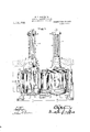
- Figure 1 is an elevat-i011 thereof, certain parts being shown in section in order to illustrate the construction more clearly, the plane of section being taken upon the line 0;a of Fig. 2.
- Fig. 2 is a plan view, certain parts being shown in section in order to more fully disclose the structure, the plane of section being taken on the line 6-?) of Fig. 1.
- Fig. 3 is a detail sectional elevation of a cylinder head with valves.
- a casting 1 supported as by the stanchions 2, and so constructed as to form a plurality of cylinders 3, 4; and 5, integral one with another.
- this casting is'removably secured, as by the bolts 6, heads 7, of which, as the same are substantially identical in construction, one only will be described in detail.
- Head 7 comprises the passages 8 and 9 respectively connected with the inlet and exhaust pipes 10 and 11.
- inlet and exhaust valves 12 and 13 are mounted inlet and exhaust valves 12 and 13, the details of the construction of which will hereinafter be given.
- a passage 14- provided with an air valve 15 and a check valve 16 adapted to admit of the running of the engine under a compressed motive fluid, and these several passages are surrounded by a jacketing space 17 through which the cooling water passes. It may here be noted that certain features herein shown and described are shown, described and'claimed in my co-pending application, Serial No. 388,285, filed August 13, 1907, and accordingly are not claimed herein. Also mounted upon head 7 are spark plugs 18, with a suitable controlling lever 19.
- a collar or cage 20 is fitted plugs
- valve seat 22 for the valve member 25, the stem 26 of which oasses upwardly through a depending gui e 27 formed upon collar 20, and thence through the collar 23, as shown. From this point, the valve stem passes through a support 28 and terminates in a cross-pin 29 above a cap 30, normally held in raised position as by the spiral spring 31 interposed bet-ween this member and an abutment formed upon the support 28.
- the independent valve seat ring 22 it may be formed of nickel steel and small in size, thus being well adapted to resist wear and substantially proof against warping.
- Lever 32 which is con nected with the inlet valve as above described, and lever 35, which bears a similar relation to the substantially. identical exhaust valve, are pivotally mounted upon the cylinder head 7 and provided at their outer extremities with the pivoted links 36and 37 respectively.
- Link 87 passes through a guide 38 secured to the cylinder head, and terminate in an antifriction roller 39 co-, acting with a cam 40 upon the cam shaft 11.
- Link 36 passing through a similar guide terminates in operative relation to the cam 4E2 upon shaft 43.
- the check valve 16 is. operated by a. cam 46 through the lever 14 and link 15.
- the air valve 15 is bolted to the head at the opposite side and controls the passage 14 whichis also controlled. by the check valve 16.
- the precise construction of the air valve 15 and check valve 16 are not features of the present invention, and arev not herein claimed, but are shown and described and claimed in my copending application, Serial No. 352,726, filed January 17 1907, to which reference may be had for a full understanding of such details. It is sufficient for the understanding of the present invention to say that the air valve 15 is adapted to admit and release compressed air to the working space of the. cylinder on a two-stroke cycle.
- the valve, 16 is a spring held check valve closing to prevent outflow from the working space so as to prevent the pressure of explosions in the cylinder from penetrating into the air starting valve. In order, however, that air may be exhausted through the air starting valve, it-is necessary that this valve 16 be opened mechanically and that is the purpose of the lever as, link 15, and cam 16. As clearly'shown in the drawings the spar:
- valves and valve acuators mounted solely upon the heads of the cylinders, and when these heads are removed by the withdrawal of the bolts 6, all these mechanisms may be removed intact.
- the construction of the inlet and exhaust valves is such as to permit of a quick wide port opening, and yet to act positively in withstanding the force of the explosions without injury to the t more delicate parts.
- a head provided with suit-- able ports and passages; gas inlet and exhaust valves therefor; suitable actuating mechanism for said valves supported and guided completely upon said head; a spark plug mounted in the head; a compressed air inlet and exhaust valve mounted on said head; actuating means therefor mounted on the head; a check valve adapted to prevent flow of air from the cylinder to the air inlet valve; and a lever mechanism supported by the head and adapted to operate the check valve.
Landscapes
- Engineering & Computer Science (AREA)
- Mechanical Engineering (AREA)
- General Engineering & Computer Science (AREA)
- Cylinder Crankcases Of Internal Combustion Engines (AREA)
- Valve-Gear Or Valve Arrangements (AREA)
Description
W. R. MOKEEN, JR. INTERNAL COMBUSTION ENGINE.
APPLIOATION FILED mun 12,1901.
Patented June 30, 1914.
3 SHEETSSHEET 1.
lllllllllllllllll 7 W. R. MQKEEN, JR. INTERNAL COMBUSTION ENGINE.
APPLICATION FILED JUNE 12, 1907.
1, 1 01,705, Patented June 30,1914.
3 SHEETSSHEET 2.
uh IH a1 PM W :1 I
r I a:
\ a I I S; 1.: 9- m I.
In: I
WITNESSES INVEN 0/? AAAAAAAAAAAAAAAAAAAAAAAAAAAAAAAAAAA c.
W. R. MOKEEN, JR. INTERNAL COMBUSTION ENGINE. APPLICATION FILED JUNE 12, 1907.
29 TILELCL I V Hi2: l
,in u 3 H x 5 i Q7 1 21 l i a J 1 mum v 26 k mmrm I 11 j n uni '2 .l] L 22 & 4 6
WITNESSES 7 A rromv TTNTTED STATME VTILLIAIE It. MGKEEN, 33., OF OMAHA, NEBRASKA, ASSIGNOR, BY MESNE ASSIGN- MZENTS, TO MCKEEN MOTOR CAR COMPANY, OF OMAHA, NEBRASKA, A OOBEOBA- 'IION OF NEW JERSEY.
INTERNAL-COMBUSTION ENGINE.
menace.
To all whom it may concern:
Be it known that 1, WILLIAM R. MoKnnN, J12, residing at Omaha, in the county of Douglas and State of Nebraska, have invented certain new and useful Improvements in Internal-Combustion Engines, of which the following is a full, clear, and exact description, such as will enable others skilled in the art to which it appertains to make and use the same.
This invention relates to engines, and with regard to the more specific features thereof to those of the internal combustion type.
One of the objects thereof is to provide an efiicient, practical engine susceptible of ready inspection and quick repair.
Another object is to provide an engine of the above type in which the more vulnerable parts may be removed as a unit.
Another object is to provide an engine in which the-valves are so formed and disposed as to consume a minimum of space and provide a wide port opening without sacrifice of simplicity and durability of construction.
Another object is to provide a multiplecylinder engine of the type first mentioned in which the several cylinders with associated parts are rigidly held in fixed relation one to another.
Other objects will be in part obvious and in part pointed out hereinafter.
The invention accordingly consists in the features of construction, combinations of elements and arrangement of parts which will be exemplified in the construction hereinafter set forth, and the scope of the application of which will be indicated in the following claims.
In the accompanying drawings, wherein is shown one of various possible embodiments of my invention, Figure 1 is an elevat-i011 thereof, certain parts being shown in section in order to illustrate the construction more clearly, the plane of section being taken upon the line 0;a of Fig. 2. Fig. 2 is a plan view, certain parts being shown in section in order to more fully disclose the structure, the plane of section being taken on the line 6-?) of Fig. 1. Fig. 3 is a detail sectional elevation of a cylinder head with valves.
Similar reference characters refer to similar parts throughout the several views of the drawings.
Specification of Letters Patent.
Application filed June 12, 1907.
Patented J 11116 30, 1914.
Serial No. 378,574.
As conducive to a ready understanding of certain features of this invention, it may here be noted that in engines of the internal combustion type, on account of the number of more or less vulnerable points there is often a loss of valuable time in locating the defective part in the event of the engine becoming inoperative. Moreover, when the cause of the breakdown is found, considerable time is often consumed in gaining access to the affected part, and the services of an expert or the use of special tools or machinery are frequently required to make an effective repair. This liability to more or less protracted delays has interfered with the adoption of motors of this type in relations in which reliable running qualities are essential, and its elimination, as well as the achievement of other valuable ends, is gained in constructions of the nature of that hereinafter set forth.
Referring now to the accompanying drawings, there is shown a casting 1 supported as by the stanchions 2, and so constructed as to form a plurality of cylinders 3, 4; and 5, integral one with another. Upon this casting is'removably secured, as by the bolts 6, heads 7, of which, as the same are substantially identical in construction, one only will be described in detail. Head 7 comprises the passages 8 and 9 respectively connected with the inlet and exhaust pipes 10 and 11. In these passages are mounted inlet and exhaust valves 12 and 13, the details of the construction of which will hereinafter be given. There is also formed in the head 7 a passage 14- provided with an air valve 15 and a check valve 16 adapted to admit of the running of the engine under a compressed motive fluid, and these several passages are surrounded by a jacketing space 17 through which the cooling water passes. It may here be noted that certain features herein shown and described are shown, described and'claimed in my co-pending application, Serial No. 388,285, filed August 13, 1907, and accordingly are not claimed herein. Also mounted upon head 7 are spark plugs 18, with a suitable controlling lever 19.
Referring now to Fig. 3 of the drawings, in which is shown the construct-ion of valves 12 and 13, the former of which will be described in detail, a collar or cage 20 is fitted plugs,
within the wall 21 and terminates atits upper end in a threaded collar 23 which takes into the upper wall 2 1 of the cylinder head. Beneath the lower edge of the collar or cage 20 is mounted a valve seat 22 for the valve member 25, the stem 26 of which oasses upwardly through a depending gui e 27 formed upon collar 20, and thence through the collar 23, as shown. From this point, the valve stem passes through a support 28 and terminates in a cross-pin 29 above a cap 30, normally held in raised position as by the spiral spring 31 interposed bet-ween this member and an abutment formed upon the support 28. By the use of the independent valve seat ring 22 it may be formed of nickel steel and small in size, thus being well adapted to resist wear and substantially proof against warping. Spring 31 thus tends to hold the valve member 25 in closed position, and the same is depressed to open the port as by the bifurcated lever 32 taking about the stem 26 above nuts 33 and 3 1 threaded thereon. Lever 32, which is con nected with the inlet valve as above described, and lever 35, which bears a similar relation to the substantially. identical exhaust valve, are pivotally mounted upon the cylinder head 7 and provided at their outer extremities with the pivoted links 36and 37 respectively. Link 87 passes through a guide 38 secured to the cylinder head, and terminate in an antifriction roller 39 co-, acting with a cam 40 upon the cam shaft 11. Link 36, passing through a similar guide terminates in operative relation to the cam 4E2 upon shaft 43.
The check valve 16 is. operated by a. cam 46 through the lever 14 and link 15. The air valve 15 is bolted to the head at the opposite side and controls the passage 14 whichis also controlled. by the check valve 16. The precise construction of the air valve 15 and check valve 16 are not features of the present invention, and arev not herein claimed, but are shown and described and claimed in my copending application, Serial No. 352,726, filed January 17 1907, to which reference may be had for a full understanding of such details. It is sufficient for the understanding of the present invention to say that the air valve 15 is adapted to admit and release compressed air to the working space of the. cylinder on a two-stroke cycle. The valve, 16 is a spring held check valve closing to prevent outflow from the working space so as to prevent the pressure of explosions in the cylinder from penetrating into the air starting valve. In order, however, that air may be exhausted through the air starting valve, it-is necessary that this valve 16 be opened mechanically and that is the purpose of the lever as, link 15, and cam 16. As clearly'shown in the drawings the spar:
' valves and valve acuators mounted solely upon the heads of the cylinders, and when these heads are removed by the withdrawal of the bolts 6, all these mechanisms may be removed intact.
The operation of the above-described embodiment of my invention is substantially as follows: Assuming that one or more cylinders of the engine are found to be defective in action, the corresponding head or heads are merely removed therefrom, and
new heads, which may be stored in accessible position, replaced for the parts removed and the engine started without delay. The defective head may then be taken to the shops, or other location, where the cause of breaking down may be investigated at leisure and the remedy conveniently and efficiently applied. The construction of the inlet and exhaust valves, moreover, is such as to permit of a quick wide port opening, and yet to act positively in withstanding the force of the explosions without injury to the t more delicate parts.
It will thus be seen that I have provided an engine in which the several objects of my invention are achieved. The entire construction is simple, and the parts in action are readily held in operat-iverelation one to widely different embodiments of this inven-,
tion could. be made without departing from the scope thereof, it is intended that all mat: terv contained in the above description or shown in the accompanying drawings shall be interpreted as illustrative and not in a limiting sense. It is also to be understood that the language used in the following claims is intended tocover all of the generic and specific features of the invention herein described. and all statements of the scope of the invention which, as a matter of lan guage, might be said to fall therebetween.
Having described my invention, what- I claim as new and desire tosecure by Letters Patent is: I v
1. In an internal combustion engine, in combination, a. cylinder, a head removably mounted upon said cylinder, a sparkplug mounted upon said head, .a check valve mounted upon said head, a lever controlling said valve and fulcrumed upon said. head,
driving means, a link connected with said lever and co-acting wlth sald driving means and are readily detachable therefrom, and guiding means upon said head coacting with said link whereby said head, spark plug, valve, lever and connecting means may be dis mounted as a unit.
2. In an internal combustion engine the combination of a head provided with suit-- able ports and passages; gas inlet and exhaust valves therefor; suitable actuating mechanism for said valves supported and guided completely upon said head; a spark plug mounted in the head; a compressed air inlet and exhaust valve mounted on said head; actuating means therefor mounted on the head; a check valve adapted to prevent flow of air from the cylinder to the air inlet valve; and a lever mechanism supported by the head and adapted to operate the check valve.
In testimony whereof I affix my signature, in the presence of two witnesses.
WILLIAM R. MQKEEN, JR. Witnesses:
H. P. VAN ARsDALn, CHAs. W. LoUoKs.
Copies of this patent may be obtained for five cents each, by addressing the Commissioner of Patents, Washington, D. G."
Priority Applications (1)
| Application Number | Priority Date | Filing Date | Title |
|---|---|---|---|
| US37857407A US1101705A (en) | 1907-06-12 | 1907-06-12 | Internal-combustion engine. |
Applications Claiming Priority (1)
| Application Number | Priority Date | Filing Date | Title |
|---|---|---|---|
| US37857407A US1101705A (en) | 1907-06-12 | 1907-06-12 | Internal-combustion engine. |
Publications (1)
| Publication Number | Publication Date |
|---|---|
| US1101705A true US1101705A (en) | 1914-06-30 |
Family
ID=3169901
Family Applications (1)
| Application Number | Title | Priority Date | Filing Date |
|---|---|---|---|
| US37857407A Expired - Lifetime US1101705A (en) | 1907-06-12 | 1907-06-12 | Internal-combustion engine. |
Country Status (1)
| Country | Link |
|---|---|
| US (1) | US1101705A (en) |
-
1907
- 1907-06-12 US US37857407A patent/US1101705A/en not_active Expired - Lifetime
Similar Documents
| Publication | Publication Date | Title |
|---|---|---|
| US1101705A (en) | Internal-combustion engine. | |
| US1052340A (en) | Valve for internal-combustion engines. | |
| US996378A (en) | Changeable-compression engine. | |
| US891346A (en) | Rotary engine. | |
| US713147A (en) | Internal-combustion engine. | |
| US713860A (en) | Exhaust-valve for internal-combustion motors. | |
| US1088259A (en) | Internal-combustion engine. | |
| US1101590A (en) | Valve for internal-combustion engines. | |
| US550324A (en) | Steam or pneumatic engine | |
| US935989A (en) | Gas-engine valve. | |
| US1234855A (en) | Explosive-engine. | |
| US785108A (en) | Valve mechanism for explosive-engines. | |
| US526761A (en) | Island | |
| US995173A (en) | Rotary steam-engine. | |
| US1126012A (en) | Fuel-tank pressure system. | |
| US1149831A (en) | Gas-engine exhaust mechanism. | |
| US543250A (en) | Third to edward c | |
| US1025385A (en) | Steam-engine. | |
| US965626A (en) | Attachment for automobile-engines. | |
| US1119462A (en) | Steam-engine valve. | |
| US899498A (en) | Starting mechanism for gas-engines. | |
| US132120A (en) | Improvement in steam-valves | |
| US1314648A (en) | Arthur holmes | |
| US515725A (en) | Combined starting and drip valve mechanism for compound engines | |
| US636048A (en) | Gasolene or gas engine. |