US11016532B2 - Display device and moving method thereof - Google Patents
Display device and moving method thereof Download PDFInfo
- Publication number
- US11016532B2 US11016532B2 US16/354,832 US201916354832A US11016532B2 US 11016532 B2 US11016532 B2 US 11016532B2 US 201916354832 A US201916354832 A US 201916354832A US 11016532 B2 US11016532 B2 US 11016532B2
- Authority
- US
- United States
- Prior art keywords
- housing
- display panel
- slide
- roller
- panel module
- Prior art date
- Legal status (The legal status is an assumption and is not a legal conclusion. Google has not performed a legal analysis and makes no representation as to the accuracy of the status listed.)
- Active
Links
Images


Classifications
-
- G—PHYSICS
- G09—EDUCATION; CRYPTOGRAPHY; DISPLAY; ADVERTISING; SEALS
- G09F—DISPLAYING; ADVERTISING; SIGNS; LABELS OR NAME-PLATES; SEALS
- G09F9/00—Indicating arrangements for variable information in which the information is built-up on a support by selection or combination of individual elements
- G09F9/30—Indicating arrangements for variable information in which the information is built-up on a support by selection or combination of individual elements in which the desired character or characters are formed by combining individual elements
- G09F9/301—Indicating arrangements for variable information in which the information is built-up on a support by selection or combination of individual elements in which the desired character or characters are formed by combining individual elements flexible foldable or roll-able electronic displays, e.g. thin LCD, OLED
-
- G—PHYSICS
- G06—COMPUTING OR CALCULATING; COUNTING
- G06F—ELECTRIC DIGITAL DATA PROCESSING
- G06F1/00—Details not covered by groups G06F3/00 - G06F13/00 and G06F21/00
- G06F1/16—Constructional details or arrangements
- G06F1/1613—Constructional details or arrangements for portable computers
- G06F1/1615—Constructional details or arrangements for portable computers with several enclosures having relative motions, each enclosure supporting at least one I/O or computing function
- G06F1/1624—Constructional details or arrangements for portable computers with several enclosures having relative motions, each enclosure supporting at least one I/O or computing function with sliding enclosures, e.g. sliding keyboard or display
-
- H—ELECTRICITY
- H04—ELECTRIC COMMUNICATION TECHNIQUE
- H04M—TELEPHONIC COMMUNICATION
- H04M1/00—Substation equipment, e.g. for use by subscribers
- H04M1/02—Constructional features of telephone sets
- H04M1/0202—Portable telephone sets, e.g. cordless phones, mobile phones or bar type handsets
- H04M1/026—Details of the structure or mounting of specific components
- H04M1/0266—Details of the structure or mounting of specific components for a display module assembly
- H04M1/0268—Details of the structure or mounting of specific components for a display module assembly including a flexible display panel
-
- G—PHYSICS
- G02—OPTICS
- G02F—OPTICAL DEVICES OR ARRANGEMENTS FOR THE CONTROL OF LIGHT BY MODIFICATION OF THE OPTICAL PROPERTIES OF THE MEDIA OF THE ELEMENTS INVOLVED THEREIN; NON-LINEAR OPTICS; FREQUENCY-CHANGING OF LIGHT; OPTICAL LOGIC ELEMENTS; OPTICAL ANALOGUE/DIGITAL CONVERTERS
- G02F1/00—Devices or arrangements for the control of the intensity, colour, phase, polarisation or direction of light arriving from an independent light source, e.g. switching, gating or modulating; Non-linear optics
- G02F1/01—Devices or arrangements for the control of the intensity, colour, phase, polarisation or direction of light arriving from an independent light source, e.g. switching, gating or modulating; Non-linear optics for the control of the intensity, phase, polarisation or colour
- G02F1/13—Devices or arrangements for the control of the intensity, colour, phase, polarisation or direction of light arriving from an independent light source, e.g. switching, gating or modulating; Non-linear optics for the control of the intensity, phase, polarisation or colour based on liquid crystals, e.g. single liquid crystal display cells
- G02F1/133—Constructional arrangements; Operation of liquid crystal cells; Circuit arrangements
- G02F1/1333—Constructional arrangements; Manufacturing methods
- G02F1/133305—Flexible substrates, e.g. plastics, organic film
-
- G—PHYSICS
- G06—COMPUTING OR CALCULATING; COUNTING
- G06F—ELECTRIC DIGITAL DATA PROCESSING
- G06F1/00—Details not covered by groups G06F3/00 - G06F13/00 and G06F21/00
- G06F1/16—Constructional details or arrangements
- G06F1/1613—Constructional details or arrangements for portable computers
- G06F1/1615—Constructional details or arrangements for portable computers with several enclosures having relative motions, each enclosure supporting at least one I/O or computing function
- G06F1/1616—Constructional details or arrangements for portable computers with several enclosures having relative motions, each enclosure supporting at least one I/O or computing function with folding flat displays, e.g. laptop computers or notebooks having a clamshell configuration, with body parts pivoting to an open position around an axis parallel to the plane they define in closed position
-
- H—ELECTRICITY
- H10—SEMICONDUCTOR DEVICES; ELECTRIC SOLID-STATE DEVICES NOT OTHERWISE PROVIDED FOR
- H10K—ORGANIC ELECTRIC SOLID-STATE DEVICES
- H10K77/00—Constructional details of devices covered by this subclass and not covered by groups H10K10/80, H10K30/80, H10K50/80 or H10K59/80
- H10K77/10—Substrates, e.g. flexible substrates
- H10K77/111—Flexible substrates
-
- G—PHYSICS
- G06—COMPUTING OR CALCULATING; COUNTING
- G06F—ELECTRIC DIGITAL DATA PROCESSING
- G06F1/00—Details not covered by groups G06F3/00 - G06F13/00 and G06F21/00
- G06F1/16—Constructional details or arrangements
- G06F1/1613—Constructional details or arrangements for portable computers
- G06F1/1633—Constructional details or arrangements of portable computers not specific to the type of enclosures covered by groups G06F1/1615 - G06F1/1626
- G06F1/1637—Details related to the display arrangement, including those related to the mounting of the display in the housing
- G06F1/1652—Details related to the display arrangement, including those related to the mounting of the display in the housing the display being flexible, e.g. mimicking a sheet of paper, or rollable
-
- G—PHYSICS
- G09—EDUCATION; CRYPTOGRAPHY; DISPLAY; ADVERTISING; SEALS
- G09G—ARRANGEMENTS OR CIRCUITS FOR CONTROL OF INDICATING DEVICES USING STATIC MEANS TO PRESENT VARIABLE INFORMATION
- G09G2380/00—Specific applications
- G09G2380/02—Flexible displays
-
- H—ELECTRICITY
- H04—ELECTRIC COMMUNICATION TECHNIQUE
- H04M—TELEPHONIC COMMUNICATION
- H04M1/00—Substation equipment, e.g. for use by subscribers
- H04M1/02—Constructional features of telephone sets
- H04M1/0202—Portable telephone sets, e.g. cordless phones, mobile phones or bar type handsets
- H04M1/0206—Portable telephones comprising a plurality of mechanically joined movable body parts, e.g. hinged housings
- H04M1/0208—Portable telephones comprising a plurality of mechanically joined movable body parts, e.g. hinged housings characterized by the relative motions of the body parts
- H04M1/0235—Slidable or telescopic telephones, i.e. with a relative translation movement of the body parts; Telephones using a combination of translation and other relative motions of the body parts
- H04M1/0237—Sliding mechanism with one degree of freedom
Definitions
- aspects of some example embodiments of the present invention relate to a display device and a driving method thereof.
- a flexible display panel is deformable like paper, and accordingly, may be used for various purposes.
- flexible display panels may be used in portable devices such as tablet PCs, mobile phones, and the like.
- a display device having a flexible display panel that can be folded or expanded may be utilized according to some embodiments.
- aspects of some example embodiments of the present invention relate to a display device and a driving method thereof.
- some example embodiments of the present invention relate to a display device including a flexible display panel, and a moving method thereof.
- the flexible display panel may be slide-extended from a housing or slide-retracted into the housing.
- wrinkles or buckles of the flexible display panel are hardly generated by tension of a user.
- the flexible display panel may be wrinkled or buckled.
- a spring-rod type of tensioner and the like may be used to pull the flexible display panel in the slide-retract direction.
- the spring-rod type tensioner When the spring-rod type tensioner is used for a long period of time, tension may be weakened, and slide-retraction of the flexible display panel may not be normally carried out due to weakened tension.
- the spring-rod type of tensioner may cause an increase not only of the weight of the display device but also the volume of the display device, thereby potentially deteriorating portability of the display device.
- aspects of some example embodiments of the present invention have been made in an effort to provide a display device having an expandable flexible display panel that can assure tension in a slide-retract direction without using an additional tensioner that pulls the flexible display panel in the slide-retract direction, and a moving method thereof.
- a display device includes: a first roller; a second roller; a gear unit that is coupled to the second roller and thus rotates with the second roller; a rail unit that is engaged with the gear unit; a housing where the rail unit is provided; and a display panel module of which one end is fixed to the housing and the other end is fixed to the second roller and thus is bent by the first roller and then rolled on the second roller, wherein the display panel module is slide-extended and slide-retracted as the gear unit and the rail unit operate while being engaged with each other.
- the display panel module may include a support film and a display panel that is adhered on the support film and includes a plurality of pixels.
- Tension applied to the support film while the display panel module is in a slide-extended state may be higher than tension applied to the support while the display panel module is in a slide-retracted state.
- a portion of the display panel, exposed to the outside while the display panel module is in a slide-retracted state, may be supported by the housing.
- the rail unit and the gear unit may be engaged with each other as a rack and pinion type.
- the rail unit and the gear unit may be engaged with each other as a chain and sprocket type.
- the rail unit may be formed integrally with the housing.
- the gear unit may include: a first gear that is coupled to the second roller; a second gear that is engaged with the rail unit; and a third gear that is engaged with the first gear and the second gear.
- the display device may further include a driver that provides a rotation force for rotating the second roller around a rotation axis.
- a display device includes: a first housing; a second housing; and a display panel module that is attached on the second housing, wherein the first housing and the second housing are slide-engaged such that the display panel module is slide-extended in a slide-extension direction and slide-retracted in a slide-retract direction, the first housing includes a roller that rolls the display panel module and a gear unit that is coupled to the roller and thus rotates together with the roller, and the second housing includes a rail unit that is engaged with the gear unit.
- the gear unit and the rail unit operate by being engaged with each other, and thus the display panel module may be rolled on the roller by a force that moves the second housing.
- the gear unit and the rail unit operate by being engaged with each other, and thus the display panel module may be unrolled from the roller by a force that moves the second housing.
- the display device may further include a driver that provides a rotation force to rotate the roller around a rotation axis, wherein the second housing moves in the slide-extension direction and the slide-retract direction by rotation of the roller.
- Tension applied to the display panel module while the display panel module is in a slide-extended state may be higher than tension applied to the display panel module while the display panel module is in a slide-retracted state.
- a method for moving a display device that includes a first housing and a second housing which are slide-engaged with each other.
- the method for moving the display device includes: moving the second housing in a slide-extension direction for a display panel module attached on the second housing to be slide-extended from the first housing; rotating a gear unit in one direction and unrolling the display panel module rolled on a roller that is connected with the gear unit from the roller as the gear unit included in the first housing and a rail unit included in the second housing are engaged with each other; and increasing tension applied to the display panel module as a radius of the display panel module rolled on the roller is reduced.
- the moving method of the display device may further include: moving the second housing in a slide-retract direction for the display panel module to be slide-retracted into the first housing; rotating the gear unit in the opposite direction and rolling the display panel module on the roller as the gear unit included in the first housing and the rail unit included in the second housing are engaged with each other; and releasing tension of the display panel module.
- a portion of the display panel module, exposed to the outside while the display panel module is in a slide-retracted state, may be supported by the second housing.
- a moving method of a display device that includes a first housing and a second housing that are slide-engaged with each other.
- the moving method of the display device includes: rotating a gear unit included in the first housing in one direction by a driver; moving the second housing in a slide-extension direction to slide-expand a display panel module attached on the second housing from the first housing as a rail unit included in the second housing is engaged with the gear unit; unrolling the display panel module rolled on a roller that is connected with the gear unit; and increasing tension applied to the display panel module as a radius of the display panel module rolled on the roller is reduced.
- the moving method of the display device display device may further include: by the driver, rotating the gear unit in the opposite direction; moving the second housing in a slide-retract direction for the display panel module to be slide-retracted into the first housing as the gear unit and the rail unit are engaged with each other; and rolling the display panel module on the roller.
- the display device having the expandable flexible display panel may assure tension in the slide-retract direction without using an additional tensioner that pulls the flexible display panel in the slide-retract direction.
- FIG. 1 shows a state that an expandable display device is in a slide-retracted state according to some example embodiments of the present invention.
- FIG. 2 shows a state that the expandable display device is in a slide-extended state according to some example embodiments of the present invention.
- FIG. 3 and FIG. 4 are cross-sectional views of an internal structure of the expandable display device according to some example embodiments of the present invention.
- FIG. 5 shows that a rail unit in a second housing and a gear unit coupled to a second roller according to some example embodiments of the present invention.
- FIG. 6 shows a connection structure of the second roller and the display panel module according to some example embodiments of the present invention.
- FIG. 7 shows a connection structure between a second roller and a display panel module according to some example embodiments of the present invention.
- FIG. 8 shows engagement of a rail unit provided in a second housing and a gear unit coupled to a second roller according to some example embodiments of the present invention.
- FIG. 9 shows a connection structure of the second roller and a display panel module according to some example embodiments of the present invention.
- FIG. 10 is a cross-sectional view of an internal structure of an expandable display device according to some example embodiments of the present invention.
- FIG. 11 is a cross-sectional view of an internal structure of an expandable display device according to some example embodiments of the present invention.
- FIG. 12 is a cross-sectional view of an internal structure of an expandable display device according to some example embodiments of the present invention.
- FIGS. 1-6 a display device according to some example embodiments of the present invention will be described with reference to FIGS. 1-6 .
- FIG. 1 shows a state that an expandable display device is in a slide-retracted state according to some example embodiments of the present invention.
- FIG. 2 shows a state that the expandable display device is in a slide-extended state according to some example embodiments of the present invention.
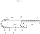
- FIG. 3 and FIG. 4 are cross-sectional views of an internal structure of the expandable display device according to some example embodiments of the present invention.
- FIG. 5 shows that a rail unit in a second housing and a gear unit coupled to a second roller according to some example embodiments of the present invention that are engaged with each other.
- FIG. 6 shows a connection structure of the second roller and the display panel module according to some example embodiments of the present invention.
- a display device includes a first housing 210 , a second housing 220 , and a display panel module 100 .
- the display panel module 100 is attached on the second housing 220 .
- the first housing 210 and the second housing 220 are slide-engaged such that the display panel module 100 is slide-expanded from the first housing 210 and the display panel module 100 is slid back into the first housing 210 .
- a direction in which the display panel module 100 is slide-expanded from the first housing 210 is called a slide-extension direction D 1
- a direction in which the display panel module 100 is slid back into the first housing 210 is called a slide-retract direction D 2 .
- the slide-extension direction D 1 and the slide-retract direction D 2 may be opposite to each other.
- the display panel module 100 When the second housing 220 moves in the slide-extension direction D 1 by a user or a driver (refer to reference numeral 260 in FIG. 3 and FIG. 4 ) while the display panel module 100 is slid back into the first housing 210 (i.e., the state shown in FIG. 1 ), the display panel module 100 is slide-extended from the first housing 210 (a state shown in FIG. 2 ). When the display panel module 100 is in the slide-extended state, an image can be displayed on a large-sized screen from the front of the display device.
- the display panel module 100 is slid back into the first housing 210 .
- An image is displayed on a relatively small-sized screen from the front of the display device when the display panel module 100 is in the slide-retracted state.
- one side of the first housing 210 which corresponds to a rear side of the display device, may be made transparent, and thus the image can also be displayed on the rear side of the display device.
- the first housing 210 may include a first roller 230 , a second roller 255 , a gear unit 250 , and the driver 260 .
- the second housing 220 may include a rail unit 240 .
- the first roller 230 is perpendicular to the slide-extension direction D 1 or the slide-retract direction D 2 , and rotates about a rotation axis in a direction that is parallel with a display surface of the display panel module 100 .
- the display surface of the display panel module 100 implies an area where an image is displayed.
- the first roller 230 rolls the display panel module 100 to bend the display panel module 100 in a direction of about 180 degrees, and thus a movement direction of the display panel module 100 can be changed in the first housing 210 when the display panel module 100 is slide-retracted and slide-extended.
- the display panel module 100 when the display panel module 100 is slide-retracted, the display panel module 100 on the second housing 220 moves in the slide-retract direction D 1 , and in the first housing 210 , the display panel module 100 moves in the slide-extension direction in the first housing 210 by the first roller 230 .
- the display panel module 100 on the second housing 220 moves in the slide-extension direction D 1 , and in the first housing 210 , the display panel module 100 moves in the slide-retract direction D 2 by the first roller 230 .
- a radius of the first roller 230 may correspond to a minimum allowable radius for bending of the display panel module 100 with respect to elements included in the display panel module 100 .
- the radius of the first roller 230 may be about 3 mm to 4 mm.
- the first roller 230 may include at least one of plastic, metal, glass, rubber, and silicon.
- the second roller 255 is located at the opposite side of the first roller 230 in the first housing 210 , and rotates about a rotation axis that is perpendicular to the slide-extension direction D 1 or the slide-retract direction D 2 and parallel with the display surface of the display panel module 100 .
- the second roller 255 may include at least one of plastic, metal, glass, rubber, or silicon.
- the gear units 250 are engaged to opposite ends of second roller 255 and thus rotate together with the second roller 255 .
- the gear units 250 are engaged with the rail units 240 located below the second housing 220 .
- the rail units 240 may be provided corresponding to the gear units 250 below the second housing 220 .
- Each of two rail units 240 may extend in a direction that is parallel with the slide-extension direction D 1 or the slide-retract direction D 2 .
- the rail unit 240 may be a rack, and the gear unit 250 may be engaged with the rail unit 240 as a pinion. That is, the rail unit 240 and the gear unit 250 may operate by being engaged as a rack and pinion type.
- the driver 260 provides a rotation force that drives the second roller 255 to rotate in a clockwise direction and a counterclockwise direction with reference to the rotation axis. That is, the driver 260 rotates the gear units 250 in the clockwise direction and the counterclockwise direction with reference to the rotation axis.
- the driver 260 may include a micro-motor that provides a rotation force to the second roller 255 . According to some example embodiments, the driver 260 can be omitted.
- the display panel module 100 includes a support film 110 , and a display panel 120 that is bonded on the support film 110 .
- One end of the support film 110 is fixed to the second housing 220 , a center portion of the support film 110 contacts the first roller 230 and thus is bent, and the other end of the support film 110 is fixed to the second roller 255 .
- the support film 110 moves to the second roller 255 through the first roller 230 , and thus a part of the support film 110 is wound on the second roller 255 .
- the support film 110 moves to the outside the first housing 210 from the second roller 255 through the first roller 230 , and then the part of the support film 110 that is wound on the second roller 255 is unwound from the second roller 255 .
- the support film 110 may be made of a flexible material that can withstand tension in the slide-extension direction D 1 and the slide-retract direction D 2 .
- the support film 110 may include at least one of plastic, metal, rubber, and silicon.
- the support film 110 may include a plurality of layers formed of at least one of plastic, metal, rubber, and silicon.
- the support film 110 may include a plurality of layers made of metal.
- the support film 110 may include one layer made of one of plastic, metal, rubber, and silicon and another layer made of another material.
- the display panel 120 may be a flexible display panel including a plurality of pixels formed on a flexible base substrate.
- the base substrate may include flexible plastic, metal, glass, and the like.
- the display panel 120 may include a touch sensor, an optical film, a protective window, and the like.
- the display panel 120 may be adhered on the support film 110 by an adhesive.
- the second housing 220 moves in the slide-extension direction D 1 , and as the second housing 220 moves, the display panel module 100 is slide-expanded.
- the support film 110 wound around the second roller 255 is unwound.
- the radius of the support film 110 rolled on the second roller 255 is reduced such that tension applied to the supplied film 110 is increased. Accordingly, the support film 110 can support the display panel 120 with high tension while the display panel module 100 is slide-expanded. That is, although an additional support body is not provided in a part of the display panel 120 , which is not supported by the second housing 220 while the display panel module 100 is in the slide-extended state, the display panel 120 can be supported by the support film 110 having high tension.
- the second housing 220 moves in the slide-retract direction D 2 , and as the second housing 220 moves, the display panel module 100 may be slide-retracted.
- the second roller 255 rolls the support film 110 while rotating around the rotation axis. Because tension is applied to the display panel module 100 while the support film 110 rolled around the second roller 255 , the display panel module 100 may be prevented from being wrinkled or buckled. Although the tension of the support film 110 is released while the display panel module 100 is in the slide-retracted stated, a portion of the display panel 120 , exposed to the outside, can be supported by the second housing 220 .
- tension applied to the support film 110 while the display panel module 100 is in the slide-extended state is higher than tension applied to the support film 110 while the display panel module 100 is in the slide-retracted state.
- the user may pull the second housing 220 in the slide-extension direction D 1 to expand the display panel module 100 .
- the second roller 255 rotates as the second housing 220 moves, and thus the support film 110 wound around the second roller 255 is unwound.
- the support film 110 can support the display panel 120 with high tension while the display panel module 100 is in the slide-extended state.
- the user may push the second housing 220 along the slide-retract direction D 2 such that the display panel module 100 can be slide-retracted.
- the second housing 220 moves, the second roller 255 rotates and thus the second roller 255 rolls the support film 110 .
- tension can be applied to the display panel module 100 .
- a force that moves the second housing 220 may be changed to tension that pulls the display panel module 100 in the slide-extension direction D 1 or tension that pulls the display panel module 100 in the slide-retract direction D 2 . That is, no additional tensioner to pull the display panel module 100 in the slide-retract direction is needed, as the rail unit 240 provided in the second housing 220 and the gear unit 250 coupled to the second roller 255 operate by being engaged with each other.
- the support film 110 includes a relatively wide first width W 1 and a relatively narrow second width W 2 .
- the first width W 1 and the second width W 2 may be widths of the support film 110 in an axis direction D 3 .
- the axis direction D 3 may be perpendicular to the slide-extension direction D 1 and the slide-retract direction D 2 in a direction that is parallel with the rotation axis of the first roller 230 or the second roller 255 .
- a portion having the first width W 1 includes one end of the support film 110
- a portion having the second width W 2 includes the other end of the support film 110 , fixed to the second housing 220 .
- the display panel 120 may be bonded to the portion having the first width W 1 .
- a width of the display panel 120 in the axis direction D 3 may be equal to or smaller than the first width W 1 .
- a third width W 3 in the axis direction D 3 of the second roller 255 and the gear units 250 may be equal to or smaller than the first width W 1 . Accordingly, the width of the display device in the axis direction D 3 does not increase by the second roller 255 and the gear units 250 .
- a width of the second roller 255 in the third direction D 3 may be equal to or greater than the second width W 2 .
- the portion of the support film 110 having the second width W 2 is wound around the second roller 255 , and the portion of the support film 110 having the first width W 1 is not wound around the second roller 255 .
- a gap between the two rail units 240 shown in FIG. 5 may be equal to a gap between the two gear units 240 shown in FIG. 6 . That is, the gap between the two rail units 240 may be equal to or greater than the second width W 2 .
- FIG. 7 a display device according to some example embodiments of the present invention will be described. Differences from the above-described FIG. 1 to FIG. 6 will be mainly described.
- FIG. 7 shows a connection structure between a second roller and a display panel module according to some example embodiments of the present invention.
- a support film 110 wholly has a first width W 1 in an axis direction D 3 .
- the display panel 120 may be adhered adjacent to one end of the support film 110 , which is fixed to a second housing 220 .
- a third width W 3 of a second roller 255 and gear units 250 in the axis direction D 3 may be greater than the first width W 1 .
- a width of the second roller 255 in the axis direction D 3 may be equal to or greater than the first width W 1 .
- the gap between the two rail units 240 shown in FIG. 5 may be equal to a gap between the two gear units 250 of FIG. 7 . That is, the gap between the two rail units 240 may be equal to or greater than the first width W 1 .
- FIG. 8 and FIG. 9 Differences from the above-described FIG. 1 to FIG. 6 will be mainly described.
- FIG. 8 shows engagement of a rail unit provided in a second housing and a gear unit coupled to a second roller according to some example embodiments of the present invention.
- FIG. 9 shows a connection structure of the second roller and a display panel module according to some example embodiments of the present invention.
- one rail 240 may be provided below a second housing 220 .
- the rail unit 240 may extend in a direction that is parallel with a slide-extension direction D 1 or a slide-retract direction D 2 at a lower center of the second housing 220 .
- One rail unit 240 is engaged with one gear unit 250 .
- Second rollers 255 are coupled to opposite sides of the gear unit 250 and thus rotate together with the rail unit 240 .
- a support film 110 includes a portion having a relatively wide width W 1 and two portions, each having a relatively narrow width W 2 ′.
- Each of the two portions of the support film 110 having the second width W 2 ′, may include a side that corresponds to an extension line of a side having the first width W 1 , extended in the slide-extension direction D 1 or slide-retract direction D 2 .
- the two portions of the support film 110 are fixed to the second rollers 255 at opposite sides of the gear unit 250 .
- a portion of the support film 110 which corresponds to the gear unit 250 , is cut and thus two portions, each having the second width W 2 ′, are formed.
- a width of each of the two rollers 255 in the axis direction D 3 may be equal to or greater than the second width W 2 ′.
- a width of the portion cut corresponding to the gear unit 250 in the axis direction D 3 may be equal to or greater than a width of the gear unit 250 .
- FIG. 10 Differences from the above-described FIG. 1 to FIG. 6 will be mainly described.
- FIG. 10 is a cross-sectional view of an internal structure of an expandable display device according to some example embodiments of the present invention.
- a rail unit 240 ′ included in a second housing 220 is a chain
- a gear unit 250 ′ included in a first housing 210 may be engaged with the rail unit 240 ′ as a sprocket. That is, the rail unit 240 ′ and the gear unit 250 ′ may operate by being engaged with each other as a chain and sprocket type.
- the chain and sprocket type of rail unit 240 ′ and gear unit 250 ′ may have the same size as described with reference to FIG. 6 or the same size as described with reference to FIG. 7 .
- one rail unit 240 ′ and one gear unit 250 ′ may be provided.
- FIG. 11 Differences from the above-described FIG. 1 to FIG. 6 will be mainly described.
- FIG. 11 is a cross-sectional view of an internal structure of an expandable display device according to some example embodiments of the present invention.
- a rack shape 221 may be formed in a bottom side of a second housing 220 . That is, the rail unit 240 may be integrally formed to the second housing 220 .
- the rack shape 221 formed in the bottom side of the second housing 220 is formed corresponding to a gear unit 250 and is thus engaged with the gear unit 250 .
- the rack shape 221 may extend in a direction that is parallel with a slide-extension direction D 1 or a slide-retract direction D 2 .
- the rack shape 221 and the gear unit 250 may have the same size as described with reference to FIG. 6 or the same size as described with reference to FIG. 7 .
- one rack shape 221 and one gear unit 250 may be provided.
- FIG. 12 Differences from the above-described FIG. 1 to FIG. 6 will be mainly described.
- FIG. 12 is a cross-sectional view of an internal structure of an expandable display device according to some example embodiments of the present invention.
- a gear unit 250 includes a plurality of gears 251 , 252 , and 253 .
- a first gear 251 is coupled to a second roller 255
- a second gear 252 is engaged with a rail unit 240
- a third gear 253 receives a rotation force from a driver 260 .
- the third gear 253 is engaged with the first gear 251 and the second gear 252 , and the first gear 251 and the second gear 252 rotate as the third gear 253 rotates.
- the second housing 220 moves in a slide-extension direction D 1 or a slide-retract direction D 2 .
- a display panel module 100 is rolled on or unrolled from the second roller 255 .
- the second gear 252 rotates in the clockwise direction or the counterclockwise direction.
- the third gear 253 transmits rotation of the second gear 252 to the first gear 251 , and as the first gear 251 rotates, the display panel module 100 is rolled on or unrolled from the second roller 255 .
- gear units 250 is formed of the plurality of gears 251 , 252 , and 253 , spatial utility inside the first housing 210 can be increased, and a gear radius can be adaptively adjusted.
- the gear unit 250 includes the three gears 251 , 252 , and 253 , but the number of gears included in the gear unit 250 is not restrictive.
Landscapes
- Engineering & Computer Science (AREA)
- Physics & Mathematics (AREA)
- Theoretical Computer Science (AREA)
- General Physics & Mathematics (AREA)
- Computer Hardware Design (AREA)
- Mathematical Physics (AREA)
- Human Computer Interaction (AREA)
- General Engineering & Computer Science (AREA)
- Nonlinear Science (AREA)
- Signal Processing (AREA)
- Chemical & Material Sciences (AREA)
- Crystallography & Structural Chemistry (AREA)
- Optics & Photonics (AREA)
- Devices For Indicating Variable Information By Combining Individual Elements (AREA)
Abstract
Description
Claims (20)
Applications Claiming Priority (2)
| Application Number | Priority Date | Filing Date | Title |
|---|---|---|---|
| KR10-2018-0088651 | 2018-07-30 | ||
| KR1020180088651A KR102477229B1 (en) | 2018-07-30 | 2018-07-30 | Display device and moving method thereof |
Publications (2)
| Publication Number | Publication Date |
|---|---|
| US20200033913A1 US20200033913A1 (en) | 2020-01-30 |
| US11016532B2 true US11016532B2 (en) | 2021-05-25 |
Family
ID=69179186
Family Applications (1)
| Application Number | Title | Priority Date | Filing Date |
|---|---|---|---|
| US16/354,832 Active US11016532B2 (en) | 2018-07-30 | 2019-03-15 | Display device and moving method thereof |
Country Status (3)
| Country | Link |
|---|---|
| US (1) | US11016532B2 (en) |
| KR (1) | KR102477229B1 (en) |
| CN (1) | CN110782783B (en) |
Cited By (20)
| Publication number | Priority date | Publication date | Assignee | Title |
|---|---|---|---|---|
| US11315447B2 (en) * | 2020-05-26 | 2022-04-26 | Wuhan China Star Optoelectronics Semiconductor Display Technology Co., Ltd. | Display device |
| US11315443B2 (en) * | 2019-07-29 | 2022-04-26 | Wuhan China Star Optoelectronics Semiconductor Display Technology Co., Ltd. | Display device |
| US11314285B2 (en) * | 2020-05-26 | 2022-04-26 | Wuhan China Star Optoelectronics Semiconductor Display Technology Co., Ltd. | Flexible display device with stretching members and transmission mechanism |
| US20220210930A1 (en) * | 2020-12-31 | 2022-06-30 | Acer Incorporated | Flexible display device and portable electronic device |
| US20220221907A1 (en) * | 2021-01-11 | 2022-07-14 | Boe Technology Group Co., Ltd. | Display assembly and display device |
| US20220357775A1 (en) * | 2019-07-30 | 2022-11-10 | Samsung Display Co., Ltd. | Display device and method for manufacturing the same |
| US11538371B2 (en) * | 2020-06-30 | 2022-12-27 | Beijing Boe Technology Development Co., Ltd. | Display apparatus and electronic device |
| US20230007112A1 (en) * | 2020-01-09 | 2023-01-05 | Lg Electronics Inc. | Mobile terminal |
| US20230017380A1 (en) * | 2019-12-23 | 2023-01-19 | Lg Electronics Inc. | Mobile terminal |
| US20230097200A1 (en) * | 2020-05-26 | 2023-03-30 | Wuhan China Star Optoelectronics Semiconductor Display Technology Co., Ltd. | Display device |
| US20230185337A1 (en) * | 2020-05-07 | 2023-06-15 | Lg Electronics Inc. | Display device |
| US20230199980A1 (en) * | 2020-07-02 | 2023-06-22 | Wuhan China Star Optoelectronics Semiconductor Display Technology Co., Ltd. | Flexible display device |
| US20230283697A1 (en) * | 2020-09-14 | 2023-09-07 | Lg Electronics Inc. | Mobile terminal |
| US20240310876A1 (en) * | 2022-06-29 | 2024-09-19 | Boe Technology Group Co., Ltd. | Flexible display device and display terminal |
| US12101896B2 (en) | 2020-05-20 | 2024-09-24 | Samsung Electronics Co., Ltd. | Electronic device including slide-out display |
| US12222756B2 (en) * | 2021-01-27 | 2025-02-11 | Kunshan Go-Visionox Opto-Electronics Co., Ltd | Support structural member and display device |
| US12346156B2 (en) | 2014-02-25 | 2025-07-01 | Medibotics Llc | Wrist-worn device with a variable-size display which is expanded by unrolling or sliding |
| US12355908B2 (en) | 2020-04-21 | 2025-07-08 | Samsung Display Co., Ltd. | Display device |
| US12513835B2 (en) | 2022-04-21 | 2025-12-30 | Apple Inc. | Electronic devices with expandable displays |
| US12537418B2 (en) | 2021-09-29 | 2026-01-27 | Samsung Electronics Co., Ltd. | Electronic device comprising drive motor |
Families Citing this family (85)
| Publication number | Priority date | Publication date | Assignee | Title |
|---|---|---|---|---|
| KR102600966B1 (en) * | 2018-09-21 | 2023-11-09 | 엘지디스플레이 주식회사 | Rollable display apparatus |
| JP1646030S (en) * | 2019-04-10 | 2021-11-08 | ||
| JP1654795S (en) * | 2019-04-10 | 2020-03-09 | Mobile phone | |
| JP1654799S (en) * | 2019-04-10 | 2020-03-09 | Mobile phone | |
| JP1654801S (en) * | 2019-04-10 | 2020-03-09 | Mobile phone | |
| JP1654802S (en) * | 2019-04-10 | 2020-03-09 | Mobile phone | |
| KR102578448B1 (en) * | 2019-06-24 | 2023-09-14 | 엘지전자 주식회사 | mobile terminal |
| CN110211505B (en) * | 2019-06-29 | 2021-08-24 | 上海天马有机发光显示技术有限公司 | A wearable display device |
| TWM592168U (en) * | 2019-07-03 | 2020-03-11 | 宏碁股份有限公司 | Electronic device |
| US11775016B2 (en) * | 2019-07-19 | 2023-10-03 | Lg Electronics Inc. | Display device |
| US12063754B2 (en) * | 2019-08-08 | 2024-08-13 | Lg Electronics Inc. | Flexible display device |
| TWI710927B (en) * | 2019-08-20 | 2020-11-21 | 宏碁股份有限公司 | Portable electronic device |
| EP4080855B1 (en) * | 2019-12-19 | 2026-02-11 | LG Electronics, Inc. | Roll-slide mobile terminal |
| KR102340786B1 (en) * | 2020-01-10 | 2021-12-17 | 엘지전자 주식회사 | Display device for vehicle |
| CN111243440B (en) * | 2020-03-11 | 2022-05-17 | 昆山国显光电有限公司 | Flexible display device |
| CN116600033A (en) * | 2020-03-16 | 2023-08-15 | 华为技术有限公司 | mobile terminal |
| US20230164248A1 (en) * | 2020-04-10 | 2023-05-25 | Lg Electronics Inc. | Flexible display device |
| CN111508355B (en) * | 2020-04-16 | 2021-06-01 | 武汉华星光电半导体显示技术有限公司 | Flexible display device |
| WO2021215565A1 (en) * | 2020-04-24 | 2021-10-28 | 엘지전자 주식회사 | Mobile terminal |
| CN113643609B (en) * | 2020-04-27 | 2022-11-01 | Oppo广东移动通信有限公司 | Display device |
| US11116091B1 (en) * | 2020-04-27 | 2021-09-07 | Wuhan China Star Optoelectronics Semiconductor Display Technology Co., Ltd. | Flexible display screen and display device |
| CN111425725B (en) * | 2020-05-21 | 2024-08-13 | 京东方科技集团股份有限公司 | Under-screen support structure and display device |
| CN111508374A (en) * | 2020-05-26 | 2020-08-07 | 武汉华星光电半导体显示技术有限公司 | Flexible display device |
| CN111510536B (en) | 2020-05-26 | 2025-04-25 | 武汉华星光电半导体显示技术有限公司 | Display device |
| CN111510538B (en) * | 2020-05-26 | 2024-09-27 | 武汉华星光电半导体显示技术有限公司 | Display device |
| WO2021246660A1 (en) | 2020-06-05 | 2021-12-09 | 삼성전자 주식회사 | Electronic device having flexible display and operation method thereof |
| WO2021246661A1 (en) | 2020-06-05 | 2021-12-09 | 삼성전자 주식회사 | Electronic device comprising flexible display and method for operating same |
| CN113766048B (en) * | 2020-06-05 | 2024-06-18 | Oppo广东移动通信有限公司 | Electronic device |
| CN113808481B (en) * | 2020-06-16 | 2023-06-13 | Oppo广东移动通信有限公司 | Display device |
| CN111798750A (en) * | 2020-06-23 | 2020-10-20 | 深圳市吉兆信息科技有限公司 | Flexible display screen device has |
| CN113851042B (en) | 2020-06-28 | 2023-06-02 | Oppo广东移动通信有限公司 | Electronic equipment |
| KR102662327B1 (en) * | 2020-07-24 | 2024-04-30 | 엘지전자 주식회사 | mobile terminal |
| KR102711607B1 (en) * | 2020-07-24 | 2024-09-30 | 엘지전자 주식회사 | Mobile terminal |
| WO2022025311A1 (en) | 2020-07-29 | 2022-02-03 | 엘지전자 주식회사 | Mobile terminal |
| KR102875433B1 (en) | 2020-09-01 | 2025-10-24 | 삼성전자주식회사 | electronic device having a flexible display |
| EP4194993A4 (en) * | 2020-09-03 | 2024-05-22 | Samsung Electronics Co., Ltd. | SLIDING ELECTRONIC APPARATUS AND METHOD FOR USING A TRANSPARENT SCREEN IN SAID ELECTRONIC APPARATUS |
| CN115943451B (en) * | 2020-09-08 | 2025-03-07 | Lg电子株式会社 | Mobile Terminal |
| KR102274481B1 (en) * | 2020-10-12 | 2021-07-08 | 삼성전자 주식회사 | Electronic device including flexible display |
| EP4187351A4 (en) * | 2020-10-12 | 2024-01-24 | Samsung Electronics Co., Ltd. | ELECTRONIC DEVICE WITH FLEXIBLE DISPLAY |
| KR102256042B1 (en) * | 2020-10-13 | 2021-05-25 | 삼성전자 주식회사 | An elelctronic device and method for inducing input |
| CN112303421B (en) * | 2020-10-30 | 2022-11-01 | 维沃移动通信有限公司 | Display module and electronic equipment |
| EP4191785A4 (en) * | 2020-10-30 | 2024-01-24 | Samsung Electronics Co., Ltd. | ANTENNA AND ELECTRONIC DEVICE THEREOF |
| WO2022098145A1 (en) * | 2020-11-06 | 2022-05-12 | 삼성전자 주식회사 | Method and electronic device comprising flexible display |
| US12613554B2 (en) | 2020-11-26 | 2026-04-28 | Lg Electronics Inc. | Extendable mobile terminal having flexible display unit |
| KR20220073233A (en) * | 2020-11-26 | 2022-06-03 | 삼성전자주식회사 | Electronic device including flexible display |
| EP4155864B1 (en) * | 2020-12-02 | 2025-05-14 | Samsung Electronics Co., Ltd. | Electronic device comprising flexible display |
| CN112489566B (en) * | 2020-12-23 | 2025-02-11 | 天津驭金机器人科技有限公司 | A screen folding mechanism |
| CN114822226B (en) * | 2021-01-19 | 2024-07-02 | 北京小米移动软件有限公司 | Electronic equipment |
| WO2022163875A1 (en) * | 2021-01-26 | 2022-08-04 | 엘지전자 주식회사 | Flexible display device |
| CN112951085B (en) * | 2021-01-29 | 2023-04-28 | Oppo广东移动通信有限公司 | Electronic device |
| CN112908177B (en) * | 2021-02-04 | 2022-09-02 | 京东方科技集团股份有限公司 | Display device |
| CN113050757A (en) * | 2021-03-12 | 2021-06-29 | 联想(北京)有限公司 | Electronic device |
| CN112991955B (en) * | 2021-03-12 | 2023-07-04 | 武汉华星光电半导体显示技术有限公司 | Flexible display module and flexible display device |
| CN113066368A (en) | 2021-03-18 | 2021-07-02 | 武汉华星光电半导体显示技术有限公司 | Display device |
| CN113160709A (en) * | 2021-04-12 | 2021-07-23 | 维沃移动通信有限公司 | Display screen assembly and electronic equipment |
| CN113163033B (en) * | 2021-04-14 | 2024-02-02 | 维沃移动通信有限公司 | Electronic equipment |
| EP4246943B1 (en) * | 2021-04-16 | 2026-04-29 | Samsung Electronics Co., Ltd. | Electronic device comprising flexible display |
| CN113124292B (en) * | 2021-04-27 | 2022-09-20 | 维沃移动通信有限公司 | Supporting structure and electronic equipment |
| KR20220155738A (en) * | 2021-05-17 | 2022-11-24 | 삼성전자주식회사 | Electronic device including flexible display |
| EP4246501B1 (en) | 2021-05-17 | 2026-03-25 | Samsung Electronics Co., Ltd. | Electronic device comprising flexible display |
| CN113114828B (en) * | 2021-05-21 | 2023-09-01 | 维沃移动通信有限公司 | Electronic equipment |
| KR102370782B1 (en) | 2021-06-13 | 2022-03-07 | 넷플러스 주식회사 | Company status prediction management system and Drive method of the Same |
| CN115529368A (en) * | 2021-06-25 | 2022-12-27 | 北京小米移动软件有限公司 | A stretchable screen structure and electronic equipment |
| CN115529366A (en) | 2021-06-25 | 2022-12-27 | 北京小米移动软件有限公司 | Slide rail mechanism, flexible screen structure and electronic equipment |
| CN115529776A (en) | 2021-06-25 | 2022-12-27 | 北京小米移动软件有限公司 | A slide rail mechanism, telescopic screen structure and electronic equipment |
| WO2023277372A1 (en) | 2021-07-02 | 2023-01-05 | 삼성전자 주식회사 | Flexible display and electronic device comprising same |
| CN115681687A (en) * | 2021-07-28 | 2023-02-03 | 华为技术有限公司 | a terminal |
| CN113707017B (en) * | 2021-08-24 | 2022-08-19 | 联想(北京)有限公司 | Flexible structure's tension mechanism and electronic equipment |
| CN113593423B (en) * | 2021-08-30 | 2025-03-25 | 京东方科技集团股份有限公司 | Display components and electronic devices |
| CN113870710B (en) * | 2021-09-29 | 2023-08-22 | 上海天马微电子有限公司 | Flexible display device |
| CN113838380A (en) * | 2021-09-30 | 2021-12-24 | 深圳市华星光电半导体显示技术有限公司 | Flexible display device and mobile terminal |
| CN216623630U (en) * | 2021-12-02 | 2022-05-27 | 云谷(固安)科技有限公司 | Support assembly and display unit |
| EP4357880A4 (en) | 2021-12-14 | 2024-11-20 | Samsung Electronics Co., Ltd. | Rollable electronic device with gear assembly |
| KR102666458B1 (en) * | 2021-12-22 | 2024-05-22 | 조민서 | Low-height Type Parking Robot with Modular Structure |
| CN114484186B (en) * | 2022-02-22 | 2024-05-17 | 上海天马微电子有限公司 | Display device and carrier |
| CN218299289U (en) * | 2022-06-02 | 2023-01-13 | 华为技术有限公司 | Terminal equipment |
| US12422893B2 (en) * | 2022-10-17 | 2025-09-23 | Motorola Mobility Llc | Electronic devices with translating flexible display and corresponding methods |
| US12449860B2 (en) | 2022-10-17 | 2025-10-21 | Motorola Mobility Llc | Electronic devices with translating flexible display and corresponding methods |
| CN115662299B (en) * | 2022-11-04 | 2025-09-09 | 武汉华星光电技术有限公司 | Display device |
| KR20240104466A (en) | 2022-12-28 | 2024-07-05 | 엘지디스플레이 주식회사 | Display device |
| CN116129748A (en) * | 2023-01-30 | 2023-05-16 | 京东方科技集团股份有限公司 | Slide-roll device and display device |
| WO2024175194A1 (en) * | 2023-02-23 | 2024-08-29 | Huawei Technologies Co., Ltd. | A system and a method for providing variable tensioning of an extendable display |
| US20240321147A1 (en) * | 2023-03-24 | 2024-09-26 | Samsung Display Co., Ltd. | Display apparatus |
| CN116453423B (en) * | 2023-03-31 | 2025-11-21 | 合肥维信诺科技有限公司 | Foldable display module and display device |
| KR20240161869A (en) * | 2023-05-03 | 2024-11-13 | 삼성디스플레이 주식회사 | Display device |
Citations (9)
| Publication number | Priority date | Publication date | Assignee | Title |
|---|---|---|---|---|
| US20060176243A1 (en) * | 2005-01-25 | 2006-08-10 | Chih-Feng Yeh | Electronic Device with Display of Continuously Adjustable Area |
| KR20110082943A (en) | 2010-01-12 | 2011-07-20 | 주식회사 다이아벨 | Mobile terminal |
| US8224407B2 (en) * | 2009-03-23 | 2012-07-17 | T-Mobile Usa, Inc. | Mobile device having a movable display and associated systems and methods |
| US20130058063A1 (en) | 2011-09-02 | 2013-03-07 | Microsoft Corporation | Expandable mobile device |
| KR20140066064A (en) | 2012-11-22 | 2014-05-30 | 임유섭 | Flexible display apparatus with the torque generating method of roller by the folding or unfolding operation power |
| US20170023978A1 (en) * | 2015-07-20 | 2017-01-26 | Samsung Electronics Co., Ltd. | Electronic device having flexible display |
| US20170064847A1 (en) * | 2014-05-21 | 2017-03-02 | Youseob Lim | Flexible display apparatus having roller that rotates by unfolding operation-force of user |
| KR20170081559A (en) | 2016-01-04 | 2017-07-12 | 신진철 | Display expansion type mobile terminal with sliding motion |
| KR20180005774A (en) | 2016-07-06 | 2018-01-17 | 삼성디스플레이 주식회사 | Rollable display device |
Family Cites Families (5)
| Publication number | Priority date | Publication date | Assignee | Title |
|---|---|---|---|---|
| KR20160058329A (en) * | 2014-11-14 | 2016-05-25 | 삼성디스플레이 주식회사 | Flexible display device |
| KR102378758B1 (en) * | 2015-06-19 | 2022-03-25 | 엘지디스플레이 주식회사 | Flexible display apparatus |
| KR102591365B1 (en) * | 2016-09-12 | 2023-10-19 | 삼성디스플레이 주식회사 | Expandable display device |
| KR102627801B1 (en) * | 2016-10-10 | 2024-01-22 | 삼성디스플레이 주식회사 | Expandable display device |
| KR102581776B1 (en) * | 2016-10-26 | 2023-09-22 | 엘지디스플레이 주식회사 | Rollable display device |
-
2018
- 2018-07-30 KR KR1020180088651A patent/KR102477229B1/en active Active
-
2019
- 2019-03-15 US US16/354,832 patent/US11016532B2/en active Active
- 2019-07-02 CN CN201910590396.2A patent/CN110782783B/en active Active
Patent Citations (10)
| Publication number | Priority date | Publication date | Assignee | Title |
|---|---|---|---|---|
| US20060176243A1 (en) * | 2005-01-25 | 2006-08-10 | Chih-Feng Yeh | Electronic Device with Display of Continuously Adjustable Area |
| US8224407B2 (en) * | 2009-03-23 | 2012-07-17 | T-Mobile Usa, Inc. | Mobile device having a movable display and associated systems and methods |
| KR20110082943A (en) | 2010-01-12 | 2011-07-20 | 주식회사 다이아벨 | Mobile terminal |
| US20130058063A1 (en) | 2011-09-02 | 2013-03-07 | Microsoft Corporation | Expandable mobile device |
| KR20140059274A (en) | 2011-09-02 | 2014-05-15 | 마이크로소프트 코포레이션 | Expandable mobile device |
| KR20140066064A (en) | 2012-11-22 | 2014-05-30 | 임유섭 | Flexible display apparatus with the torque generating method of roller by the folding or unfolding operation power |
| US20170064847A1 (en) * | 2014-05-21 | 2017-03-02 | Youseob Lim | Flexible display apparatus having roller that rotates by unfolding operation-force of user |
| US20170023978A1 (en) * | 2015-07-20 | 2017-01-26 | Samsung Electronics Co., Ltd. | Electronic device having flexible display |
| KR20170081559A (en) | 2016-01-04 | 2017-07-12 | 신진철 | Display expansion type mobile terminal with sliding motion |
| KR20180005774A (en) | 2016-07-06 | 2018-01-17 | 삼성디스플레이 주식회사 | Rollable display device |
Cited By (30)
| Publication number | Priority date | Publication date | Assignee | Title |
|---|---|---|---|---|
| US12346156B2 (en) | 2014-02-25 | 2025-07-01 | Medibotics Llc | Wrist-worn device with a variable-size display which is expanded by unrolling or sliding |
| US11315443B2 (en) * | 2019-07-29 | 2022-04-26 | Wuhan China Star Optoelectronics Semiconductor Display Technology Co., Ltd. | Display device |
| US12153469B2 (en) * | 2019-07-30 | 2024-11-26 | Samsung Display Co., Ltd. | Display device and method for manufacturing the same |
| US20220357775A1 (en) * | 2019-07-30 | 2022-11-10 | Samsung Display Co., Ltd. | Display device and method for manufacturing the same |
| US20230017380A1 (en) * | 2019-12-23 | 2023-01-19 | Lg Electronics Inc. | Mobile terminal |
| US12267447B2 (en) * | 2019-12-23 | 2025-04-01 | Lg Electronics Inc. | Mobile terminal |
| US20230007112A1 (en) * | 2020-01-09 | 2023-01-05 | Lg Electronics Inc. | Mobile terminal |
| US12284307B2 (en) * | 2020-01-09 | 2025-04-22 | Lg Electronics Inc. | Mobile terminal |
| US12355908B2 (en) | 2020-04-21 | 2025-07-08 | Samsung Display Co., Ltd. | Display device |
| US20230185337A1 (en) * | 2020-05-07 | 2023-06-15 | Lg Electronics Inc. | Display device |
| US12210385B2 (en) * | 2020-05-07 | 2025-01-28 | Lg Electronics Inc. | Display device including flexible display panel and panel roller |
| US12101896B2 (en) | 2020-05-20 | 2024-09-24 | Samsung Electronics Co., Ltd. | Electronic device including slide-out display |
| US11314285B2 (en) * | 2020-05-26 | 2022-04-26 | Wuhan China Star Optoelectronics Semiconductor Display Technology Co., Ltd. | Flexible display device with stretching members and transmission mechanism |
| US11315447B2 (en) * | 2020-05-26 | 2022-04-26 | Wuhan China Star Optoelectronics Semiconductor Display Technology Co., Ltd. | Display device |
| US11809231B2 (en) * | 2020-05-26 | 2023-11-07 | Wuhan China Star Optoelectronics Semiconductor Display Technology Co., Ltd. | Display device with flexible display panel connected to transmission mechanism |
| US20230097200A1 (en) * | 2020-05-26 | 2023-03-30 | Wuhan China Star Optoelectronics Semiconductor Display Technology Co., Ltd. | Display device |
| US11538371B2 (en) * | 2020-06-30 | 2022-12-27 | Beijing Boe Technology Development Co., Ltd. | Display apparatus and electronic device |
| US20230199980A1 (en) * | 2020-07-02 | 2023-06-22 | Wuhan China Star Optoelectronics Semiconductor Display Technology Co., Ltd. | Flexible display device |
| US11800657B2 (en) * | 2020-07-02 | 2023-10-24 | Wuhan China Star Optoelectronics Semiconductor Display Technology Co., Ltd. | Flexible display device |
| US20230283697A1 (en) * | 2020-09-14 | 2023-09-07 | Lg Electronics Inc. | Mobile terminal |
| US12418602B2 (en) * | 2020-09-14 | 2025-09-16 | Lg Electronics Inc. | Mobile terminal |
| US11602063B2 (en) * | 2020-12-31 | 2023-03-07 | Acer Incorporated | Flexible display device and portable electronic device |
| US20220210930A1 (en) * | 2020-12-31 | 2022-06-30 | Acer Incorporated | Flexible display device and portable electronic device |
| US11619975B2 (en) * | 2021-01-11 | 2023-04-04 | Boe Technology Group Co., Ltd. | Display assembly and display device |
| US20220221907A1 (en) * | 2021-01-11 | 2022-07-14 | Boe Technology Group Co., Ltd. | Display assembly and display device |
| US12222756B2 (en) * | 2021-01-27 | 2025-02-11 | Kunshan Go-Visionox Opto-Electronics Co., Ltd | Support structural member and display device |
| US12537418B2 (en) | 2021-09-29 | 2026-01-27 | Samsung Electronics Co., Ltd. | Electronic device comprising drive motor |
| US12513835B2 (en) | 2022-04-21 | 2025-12-30 | Apple Inc. | Electronic devices with expandable displays |
| US20240310876A1 (en) * | 2022-06-29 | 2024-09-19 | Boe Technology Group Co., Ltd. | Flexible display device and display terminal |
| US12253886B2 (en) * | 2022-06-29 | 2025-03-18 | Boe Technology Group Co., Ltd. | Flexible display device and display terminal |
Also Published As
| Publication number | Publication date |
|---|---|
| KR102477229B1 (en) | 2022-12-13 |
| US20200033913A1 (en) | 2020-01-30 |
| CN110782783A (en) | 2020-02-11 |
| KR20200013821A (en) | 2020-02-10 |
| CN110782783B (en) | 2023-03-14 |
Similar Documents
| Publication | Publication Date | Title |
|---|---|---|
| US11016532B2 (en) | Display device and moving method thereof | |
| US11971753B2 (en) | Electronic device with flexible display structures | |
| EP2751639B1 (en) | Expandable mobile device | |
| CN107342019B (en) | Rollable display device | |
| EP3477424B1 (en) | Foldable display | |
| US10985333B2 (en) | Flexible display apparatus and rollable display apparatus comprising the same | |
| KR102636685B1 (en) | Rollable Display | |
| CN107895541B (en) | Display device | |
| CN105096743B (en) | Flexible display apparatus | |
| JP7340109B2 (en) | electronic device | |
| CN114694502B (en) | Display device | |
| KR20180006533A (en) | Rollable display device | |
| CN107342018A (en) | Rollable display | |
| US12249259B2 (en) | Rollable display device with extending arms and fixing bar | |
| JP2007529776A (en) | Electronic panel device that can be rolled | |
| CN114677911B (en) | Display device | |
| EP4006883B1 (en) | Rollable display device | |
| CN113851052A (en) | Sliding and rolling screen mechanism and display device | |
| TWI891157B (en) | Display device | |
| EP3876078B1 (en) | Flexible display device | |
| CN115482723A (en) | Display device | |
| CN118280211A (en) | Display device | |
| HK1178634B (en) | Expandable mobile device |
Legal Events
| Date | Code | Title | Description |
|---|---|---|---|
| AS | Assignment |
Owner name: SAMSUNG DISPLAY CO., LTD., KOREA, REPUBLIC OF Free format text: ASSIGNMENT OF ASSIGNORS INTEREST;ASSIGNOR:YANG, JEONG DO;REEL/FRAME:048611/0922 Effective date: 20190103 |
|
| FEPP | Fee payment procedure |
Free format text: ENTITY STATUS SET TO UNDISCOUNTED (ORIGINAL EVENT CODE: BIG.); ENTITY STATUS OF PATENT OWNER: LARGE ENTITY |
|
| STPP | Information on status: patent application and granting procedure in general |
Free format text: FINAL REJECTION MAILED |
|
| STPP | Information on status: patent application and granting procedure in general |
Free format text: DOCKETED NEW CASE - READY FOR EXAMINATION |
|
| STPP | Information on status: patent application and granting procedure in general |
Free format text: NON FINAL ACTION MAILED |
|
| STPP | Information on status: patent application and granting procedure in general |
Free format text: RESPONSE TO NON-FINAL OFFICE ACTION ENTERED AND FORWARDED TO EXAMINER |
|
| STPP | Information on status: patent application and granting procedure in general |
Free format text: RESPONSE AFTER FINAL ACTION FORWARDED TO EXAMINER |
|
| STPP | Information on status: patent application and granting procedure in general |
Free format text: NOTICE OF ALLOWANCE MAILED -- APPLICATION RECEIVED IN OFFICE OF PUBLICATIONS |
|
| STPP | Information on status: patent application and granting procedure in general |
Free format text: PUBLICATIONS -- ISSUE FEE PAYMENT RECEIVED |
|
| STPP | Information on status: patent application and granting procedure in general |
Free format text: PUBLICATIONS -- ISSUE FEE PAYMENT VERIFIED |
|
| STCF | Information on status: patent grant |
Free format text: PATENTED CASE |
|
| MAFP | Maintenance fee payment |
Free format text: PAYMENT OF MAINTENANCE FEE, 4TH YEAR, LARGE ENTITY (ORIGINAL EVENT CODE: M1551); ENTITY STATUS OF PATENT OWNER: LARGE ENTITY Year of fee payment: 4 |