US11014282B2 - Apparatus and process for aseptic molding of a container starting from a parison made of a thermoplastic material - Google Patents
Apparatus and process for aseptic molding of a container starting from a parison made of a thermoplastic material Download PDFInfo
- Publication number
- US11014282B2 US11014282B2 US16/467,796 US201816467796A US11014282B2 US 11014282 B2 US11014282 B2 US 11014282B2 US 201816467796 A US201816467796 A US 201816467796A US 11014282 B2 US11014282 B2 US 11014282B2
- Authority
- US
- United States
- Prior art keywords
- fluid
- aseptic
- compensating chamber
- valve
- mould
- Prior art date
- Legal status (The legal status is an assumption and is not a legal conclusion. Google has not performed a legal analysis and makes no representation as to the accuracy of the status listed.)
- Active, expires
Links
- 238000000465 moulding Methods 0.000 title claims abstract description 50
- 238000000034 method Methods 0.000 title claims abstract description 18
- 239000012815 thermoplastic material Substances 0.000 title claims abstract description 14
- 239000012530 fluid Substances 0.000 claims abstract description 135
- 238000007664 blowing Methods 0.000 claims abstract description 57
- 230000001954 sterilising effect Effects 0.000 claims abstract description 14
- 239000003795 chemical substances by application Substances 0.000 claims abstract description 6
- 238000004891 communication Methods 0.000 claims description 34
- 238000011109 contamination Methods 0.000 claims description 27
- 230000037361 pathway Effects 0.000 claims description 9
- 238000011084 recovery Methods 0.000 claims description 3
- 238000004659 sterilization and disinfection Methods 0.000 description 8
- 230000003584 silencer Effects 0.000 description 3
- MHAJPDPJQMAIIY-UHFFFAOYSA-N Hydrogen peroxide Chemical compound OO MHAJPDPJQMAIIY-UHFFFAOYSA-N 0.000 description 2
- 239000000356 contaminant Substances 0.000 description 2
- 238000010586 diagram Methods 0.000 description 2
- 238000002955 isolation Methods 0.000 description 2
- 230000007547 defect Effects 0.000 description 1
- 238000005516 engineering process Methods 0.000 description 1
- 239000000463 material Substances 0.000 description 1
- 210000000056 organ Anatomy 0.000 description 1
- 230000000737 periodic effect Effects 0.000 description 1
- 239000004033 plastic Substances 0.000 description 1
- 238000007789 sealing Methods 0.000 description 1
- 238000000926 separation method Methods 0.000 description 1
- 230000035939 shock Effects 0.000 description 1
- 238000009424 underpinning Methods 0.000 description 1
Images


Classifications
-
- B—PERFORMING OPERATIONS; TRANSPORTING
- B29—WORKING OF PLASTICS; WORKING OF SUBSTANCES IN A PLASTIC STATE IN GENERAL
- B29C—SHAPING OR JOINING OF PLASTICS; SHAPING OF MATERIAL IN A PLASTIC STATE, NOT OTHERWISE PROVIDED FOR; AFTER-TREATMENT OF THE SHAPED PRODUCTS, e.g. REPAIRING
- B29C49/00—Blow-moulding, i.e. blowing a preform or parison to a desired shape within a mould; Apparatus therefor
- B29C49/42—Component parts, details or accessories; Auxiliary operations
- B29C49/46—Component parts, details or accessories; Auxiliary operations characterised by using particular environment or blow fluids other than air
-
- B—PERFORMING OPERATIONS; TRANSPORTING
- B29—WORKING OF PLASTICS; WORKING OF SUBSTANCES IN A PLASTIC STATE IN GENERAL
- B29C—SHAPING OR JOINING OF PLASTICS; SHAPING OF MATERIAL IN A PLASTIC STATE, NOT OTHERWISE PROVIDED FOR; AFTER-TREATMENT OF THE SHAPED PRODUCTS, e.g. REPAIRING
- B29C49/00—Blow-moulding, i.e. blowing a preform or parison to a desired shape within a mould; Apparatus therefor
- B29C49/28—Blow-moulding apparatus
- B29C49/30—Blow-moulding apparatus having movable moulds or mould parts
- B29C49/36—Blow-moulding apparatus having movable moulds or mould parts rotatable about one axis
-
- B—PERFORMING OPERATIONS; TRANSPORTING
- B29—WORKING OF PLASTICS; WORKING OF SUBSTANCES IN A PLASTIC STATE IN GENERAL
- B29C—SHAPING OR JOINING OF PLASTICS; SHAPING OF MATERIAL IN A PLASTIC STATE, NOT OTHERWISE PROVIDED FOR; AFTER-TREATMENT OF THE SHAPED PRODUCTS, e.g. REPAIRING
- B29C49/00—Blow-moulding, i.e. blowing a preform or parison to a desired shape within a mould; Apparatus therefor
- B29C49/42—Component parts, details or accessories; Auxiliary operations
- B29C49/56—Opening, closing or clamping means
- B29C49/5601—Mechanically operated, i.e. closing or opening of the mould parts is done by mechanic means
-
- B—PERFORMING OPERATIONS; TRANSPORTING
- B29—WORKING OF PLASTICS; WORKING OF SUBSTANCES IN A PLASTIC STATE IN GENERAL
- B29C—SHAPING OR JOINING OF PLASTICS; SHAPING OF MATERIAL IN A PLASTIC STATE, NOT OTHERWISE PROVIDED FOR; AFTER-TREATMENT OF THE SHAPED PRODUCTS, e.g. REPAIRING
- B29C49/00—Blow-moulding, i.e. blowing a preform or parison to a desired shape within a mould; Apparatus therefor
- B29C49/42—Component parts, details or accessories; Auxiliary operations
- B29C49/46—Component parts, details or accessories; Auxiliary operations characterised by using particular environment or blow fluids other than air
- B29C2049/4602—Blowing fluids
- B29C2049/4635—Blowing fluids being sterile
-
- B29C2049/4694—
-
- B—PERFORMING OPERATIONS; TRANSPORTING
- B29—WORKING OF PLASTICS; WORKING OF SUBSTANCES IN A PLASTIC STATE IN GENERAL
- B29C—SHAPING OR JOINING OF PLASTICS; SHAPING OF MATERIAL IN A PLASTIC STATE, NOT OTHERWISE PROVIDED FOR; AFTER-TREATMENT OF THE SHAPED PRODUCTS, e.g. REPAIRING
- B29C49/00—Blow-moulding, i.e. blowing a preform or parison to a desired shape within a mould; Apparatus therefor
- B29C49/42—Component parts, details or accessories; Auxiliary operations
- B29C49/46—Component parts, details or accessories; Auxiliary operations characterised by using particular environment or blow fluids other than air
- B29C2049/4673—Environments
- B29C2049/4697—Clean room
-
- B—PERFORMING OPERATIONS; TRANSPORTING
- B29—WORKING OF PLASTICS; WORKING OF SUBSTANCES IN A PLASTIC STATE IN GENERAL
- B29C—SHAPING OR JOINING OF PLASTICS; SHAPING OF MATERIAL IN A PLASTIC STATE, NOT OTHERWISE PROVIDED FOR; AFTER-TREATMENT OF THE SHAPED PRODUCTS, e.g. REPAIRING
- B29C49/00—Blow-moulding, i.e. blowing a preform or parison to a desired shape within a mould; Apparatus therefor
- B29C49/42—Component parts, details or accessories; Auxiliary operations
- B29C49/56—Opening, closing or clamping means
- B29C2049/566—Locking means
-
- B—PERFORMING OPERATIONS; TRANSPORTING
- B29—WORKING OF PLASTICS; WORKING OF SUBSTANCES IN A PLASTIC STATE IN GENERAL
- B29C—SHAPING OR JOINING OF PLASTICS; SHAPING OF MATERIAL IN A PLASTIC STATE, NOT OTHERWISE PROVIDED FOR; AFTER-TREATMENT OF THE SHAPED PRODUCTS, e.g. REPAIRING
- B29C2949/00—Indexing scheme relating to blow-moulding
- B29C2949/07—Preforms or parisons characterised by their configuration
- B29C2949/0715—Preforms or parisons characterised by their configuration the preform having one end closed
-
- B—PERFORMING OPERATIONS; TRANSPORTING
- B29—WORKING OF PLASTICS; WORKING OF SUBSTANCES IN A PLASTIC STATE IN GENERAL
- B29C—SHAPING OR JOINING OF PLASTICS; SHAPING OF MATERIAL IN A PLASTIC STATE, NOT OTHERWISE PROVIDED FOR; AFTER-TREATMENT OF THE SHAPED PRODUCTS, e.g. REPAIRING
- B29C49/00—Blow-moulding, i.e. blowing a preform or parison to a desired shape within a mould; Apparatus therefor
- B29C49/02—Combined blow-moulding and manufacture of the preform or the parison
- B29C49/06—Injection blow-moulding
-
- B—PERFORMING OPERATIONS; TRANSPORTING
- B29—WORKING OF PLASTICS; WORKING OF SUBSTANCES IN A PLASTIC STATE IN GENERAL
- B29C—SHAPING OR JOINING OF PLASTICS; SHAPING OF MATERIAL IN A PLASTIC STATE, NOT OTHERWISE PROVIDED FOR; AFTER-TREATMENT OF THE SHAPED PRODUCTS, e.g. REPAIRING
- B29C49/00—Blow-moulding, i.e. blowing a preform or parison to a desired shape within a mould; Apparatus therefor
- B29C49/42—Component parts, details or accessories; Auxiliary operations
- B29C49/42403—Purging or cleaning the blow-moulding apparatus
-
- B—PERFORMING OPERATIONS; TRANSPORTING
- B29—WORKING OF PLASTICS; WORKING OF SUBSTANCES IN A PLASTIC STATE IN GENERAL
- B29K—INDEXING SCHEME ASSOCIATED WITH SUBCLASSES B29B, B29C OR B29D, RELATING TO MOULDING MATERIALS OR TO MATERIALS FOR MOULDS, REINFORCEMENTS, FILLERS OR PREFORMED PARTS, e.g. INSERTS
- B29K2067/00—Use of polyesters or derivatives thereof, as moulding material
- B29K2067/003—PET, i.e. poylethylene terephthalate
-
- B—PERFORMING OPERATIONS; TRANSPORTING
- B29—WORKING OF PLASTICS; WORKING OF SUBSTANCES IN A PLASTIC STATE IN GENERAL
- B29L—INDEXING SCHEME ASSOCIATED WITH SUBCLASS B29C, RELATING TO PARTICULAR ARTICLES
- B29L2031/00—Other particular articles
- B29L2031/712—Containers; Packaging elements or accessories, Packages
- B29L2031/7158—Bottles
Definitions
- the present invention relates to an apparatus and a process for aseptic molding of a container starting from parisons made of a thermoplastic material.
- the invention is applicable in the sector of aseptic molding of containers made of plastic material, such as PET bottles.
- Each molding station comprises a mould consisting of two half-moulds that reproduce the shape of the sides of the container to be obtained.
- a profiling element of the bottom of the container known in the sector as a “bottom”, which engages with the half-moulds in order to define a molding cavity.
- the two half-moulds are neared and maintained closed by a mechanical locking system.
- a blower or sealing nozzle is neared to the neck of the parison and closes, and maintains airtight, the mouth thereof. Pressurised air is blown through the nozzle inside the parison.
- a first step known as the pre-blowing step
- air is blown at a maximum pressure of about 16 bar.
- a stretching rod, slidable inside the blowing nozzle, is simultaneously and gradually introduced into the parison until it reaches the bottom. After touching the bottom, the stretching rod continues its linear stroke during which the tubular body of the parison is stretched up to when the parison reaches substantially the desired length of the container to be obtained.
- the air is blown at a maximum pressure of about 40 bar, thus determining the expansion of the parison up until it adheres to the internal walls of the half-moulds and the bottom. Simultaneously, the stretching rod starts to retract until it exits from the container. On conclusion, the blowing air is maintained for a few instants inside the container so as to consolidate the molding of the container.
- the air is then discharged through the blower nozzle so as to return the inside of the container to atmospheric pressure, and then the container is removed from the mould.
- the two half-moulds are stressed by very high pressures which can cause deformations in the mould and be converted into evident defects in the shape of the finished containers, where the seam line generated by the two flanked half-moulds is perceptible both to the eye and to the touch.
- the simple mould locking system is not sufficient to compensate for these deformations.
- the closing force is applied by introducing a fluid under pressure (for example compressed air) in a confined chamber between one or the two half-moulds and the relative mechanical support (for example the mould-holder).
- a fluid under pressure for example compressed air
- Document EP2559545 describes a compensation system of the deformations of the mould in which the force exerted on the half-mould by the pressurised fluid has at least two components lying in different directions.
- the pressurised fluid is also sterile.
- the Applicant has developed a molding apparatus in aseptic conditions, in which the molding rotary carousel is protected by an isolation device suitable for defining a controlled-contamination environment, while the movement means for moving the carousel and moulds are located outside the isolation device (see European patent EP2246176).
- the sterilisation step involves, in particular, the gripping members, the stretching rod and the blowing air management circuit.
- the technical task underpinning the present invention is to provide an aseptic apparatus and process for molding containers starting from parisons made of a thermoplastic material, which obviate the drawbacks of the prior art as described in the foregoing.
- an aim of the present invention is to provide an aseptic apparatus and process for molding containers starting from parisons made of a thermoplastic material, which enable obtaining containers having a seam line that is substantially not perceptible, i.e. containers of a higher quality, guaranteeing at the same time a degree of sterilisation compatible with aseptic technology.
- an aseptic molding apparatus for molding containers starting from parisons made of a thermoplastic material comprising:
- the first discharge line is preferably in fluid communication with the controlled-contamination environment.
- the second circuit preferably comprises driving means operatively active on the first and second aseptic valve to allow introduction of the first fluid into the compensating chamber from the first supply line through the first aseptic valve and said inlet of the compensating chamber until the molding apparatus is in a blowing configuration, and to allow circulation of the second fluid coming from the first supply line through said first aseptic valve, said inlet, said compensating chamber, said outlet, said second aseptic valve and said first discharge line until the molding apparatus is in a sterilisation configuration.
- the compensating chamber has a plurality of inlets and outlets for the first fluid and/or the second fluid.
- the compensating chamber is afforded between the first support and the first half-mould.
- the first support is crossed by a first through-channel leading to the inlet of the compensating chamber and a second through-channel leading to the outlet of the compensating chamber.
- the through-channels are distinct and distanced from one another.
- the mould comprises an arm that is rotatable about a hinge axis, said first support being solidly constrained to said arm and said compensating chamber being afforded between said first support and said arm.
- the first fluid is preferably a gaseous medium having a pressure of 15-20 bar or 30-45 bar and said second fluid contains a sterilising agent.
- the first circuit preferably comprises:
- the apparatus further and preferably comprises a third discharge circuit of the first fluid from the parison or from the molded container, comprising:
- the third circuit further and preferably comprises a seventh valve and a non-return valve which are arranged, respectively, along a first pathway which goes from said fifth valve towards the second discharge line, and along a second pathway which goes from said fifth valve towards a recovery circuit.
- the step of introducing the first fluid into the compensating chamber is preferably carried out by opening a first aseptic valve which places a first supply line of the first fluid in fluid communication with said inlet and closing a second aseptic valve located downstream of said outlet.
- the step of evacuating the first fluid from the compensating chamber is preferably carried out by closing the first aseptic valve and opening the second aseptic valve which places said outlet in communication with a first discharge line.
- the step of sterilising the compensating chamber is preferably carried out by opening said first aseptic valve and the second aseptic valve and feeding said first supply line with the second fluid.
- the step of introducing the first fluid into the compensating chamber at least partly overlaps the step of blowing the first fluid into the parison or takes place prior to the step of blowing the first fluid into the parison.
- the step of blowing the first fluid into the parison comprises a step of pre-blowing wherein the first fluid is blown into the parison at a pressure of 15-20 bar and a step of blowing wherein the first fluid is blown into the parison at a pressure of 30-45 bar, said step of introducing the first fluid into the compensating chamber taking place simultaneously to said step of pre-blowing.
- FIG. 1 illustrates an aseptic molding apparatus of containers starting from parisons made of a thermoplastic material according to the present invention, in a broken view;
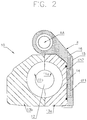
- FIG. 2 illustrates a mould of the aseptic molding apparatus of FIG. 1 , in cross-section
- FIGS. 3, 4 and 5 illustrate the pneumatic circuit diagram for supply and discharge of the first fluid and the second fluid of the apparatus of FIG. 1 , according to three different embodiments.
- the number 100 indicates an aseptic molding apparatus for containers starting from parisons made of thermoplastic material.
- the aseptic molding apparatus 100 comprises a rotating carousel 101 , on which a plurality of moulds 10 is arranged.
- the rotating carousel 101 is situated inside a controlled-contamination environment 102 protected by an insulating device 103 .
- the movement means of the rotating carousel 101 and the moulds 10 are situated outside the insulating device 103 , i.e. in a non-sterile environment.
- Each mould 10 comprises a first half-mould 11 a and a second half-mould 11 b that can be brought together to define at least a housing cavity 12 for housing a parison 20 .
- the mould 10 further comprises a first support 13 a to which said first half-mould 11 a is integrally constrained and a second support 13 b to which said second half-mould 11 b is integrally constrained.
- the mould 10 preferably has a fixed support and another movable support.
- FIG. 2 illustrates a mould 10 which also comprises an arm B rotatable about a hinge axis AA.
- the movable support in this case is 13 a which, being integrally constrained to the arm B, rotates therewith, while the fixed support is 13 b.
- both supports 13 a , 13 b (and the relative half-moulds 11 a , 11 b , integrally constrained thereto) can rotate about a common hinge axis so that the mould 10 is of the “book” type.
- the mould 10 is of the “linear” type, i.e. the supports (and the relative half-moulds, integrally constrained thereto) are mutually neared and distanced by translation.
- the mould 10 preferably comprises a bottom (not illustrated) which cooperates with the half-moulds 11 a , 11 b in order to mold the bottom of the container.
- At least a compensating chamber 14 is afforded between the first support 13 a and the first half-mould 11 a.
- This embodiment is schematically illustrated together with the circuit diagrams of FIGS. 4-5 .
- the compensating chamber 14 advantageously has at least an inlet 15 and at least an outlet 16 .
- the first support 13 a is preferably crossed by a first through-channel leading to the inlet 15 of the compensating chamber 14 and a second through-channel leading to the outlet 16 of the compensating chamber 14 .
- the two through-channels are distinct and distanced from one another.
- the compensating chamber 14 is afforded between the first support 13 a (movable) and the arm B.
- the compensating chamber 14 has at least an inlet 15 and at least an outlet 16 .
- the arm B is preferably crossed by a first through-channel ch 1 that places the inlet 15 and the compensating chamber 14 in communication, and a second through-channel ch 2 placing the outlet 16 and the compensating chamber 14 in fluid communication.
- the two through-channels ch 1 , ch 2 are distinct and distanced from one another.
- the apparatus 100 comprises a first circuit 30 configured for blowing a first fluid into the parison 20 and a second circuit 40 configured to supply the compensating chamber 14 with a first fluid or with a second fluid.
- the first fluid is preferably a gaseous medium (for example air or sterile air) having a pressure of 15-20 bar or 30-45 bar.
- a gaseous medium for example air or sterile air
- the second fluid contains a sterilising agent.
- the second fluid contains hydrogen peroxide.
- the second circuit 40 comprises:
- the first discharge line 44 is preferably in fluid communication with said controlled-contamination environment 102 .
- the first and the second aseptic valve 41 , 43 are commanded by driving means 45 , 46 which are configured in such a way that:
- the driving means 45 , 46 preferably comprise a first driving valve 45 configured to command the first aseptic valve 41 and a second driving valve 46 configured to command the second aseptic valve 43 .
- the driving valves 45 , 46 consist of two-way two-position valves of known type.
- the first circuit 30 comprises:
- the pre-blowing line P 1 supplies the first fluid having a pressure comprised between 15 bar and 20 bar and the blowing line P 2 supplies the first fluid having a pressure comprised between 30 bar and 45 bar.
- Two further driving valves 33 , 34 are included (denoted as the third and fourth driving valves) and are configured to respectively command the third aseptic valve 31 and the fourth aseptic valve 32 .
- the third and fourth driving valves 33 , 34 consist of two-way two-position valves of known type.
- the first supply line 42 is separate with respect to the supply lines of pre-blowing fluid and blowing fluid P 1 , P 2 .
- FIG. 4 illustrates a second embodiment which, with respect to FIG. 3 , differs only in the different positioning of the compensating chamber 14 .
- the first supply line 42 is in fluid communication with the blowing line P 2 .
- a third circuit 50 comprising:
- the sixth aseptic valve 53 is configured to establish a selective communication between an inside of the parison 20 or of the molded container and a third discharge line 60 is in fluid communication with said controlled-contamination environment 102 .
- the third discharge line 60 is preferably independent of the first discharge line 44 so as to avoid the risk of any counter-pressures in a case of contemporaneous release of the fluid from inside the parison/container and from the compensating chamber 14 (see FIGS. 3 and 4 ).
- the third discharge line and the first discharge line 44 are connected.
- a silencer 54 is linked to the second discharge line 52 and damps the shock wave created by the pressurised fluid.
- the silencer 54 is located in a non-sterile zone.
- the fifth valve 51 and the sixth aseptic valve 53 are commanded respectively by a fifth driving valve 55 and a sixth driving valve 56 , which are configured in such a way that the opening of the fifth valve 51 and the closing of the sixth aseptic valve 53 take place in an alternating order. In this way, the first fluid discharges through one or other of the valves 51 , 53 .
- the fifth valve 51 is normally closed and receives, during a first discharge step, an opening C 1 command from the fifth driving valve 55 in response to a detecting of a pressure of the first fluid in the parison 20 or in the molded container greater than a predetermined value.
- the sixth aseptic valve 53 is normally open and receives a closing C 2 command from the sixth driving valve 56 in response to a detecting of a pressure of the first fluid in the parison 20 or in the molded container lower than a predetermined value.
- the predetermined value is preferably comprised between 0.5 bar and 3 bar.
- the fifth and sixth driving valves 55 , 56 consist of two-way two-position valves of known type.
- the third circuit 50 preferably further comprises a seventh valve 57 and a non-return valve 58 which are arranged, respectively, along a first pathway T 1 which goes from said fifth valve 51 towards the second discharge line 52 , and along a second pathway T 2 which goes from said fifth valve 51 towards a recovery circuit 59 .
- the fluid recovered in this way can be used for example for the pre-blowing.
- All the driving valves 45 , 46 , 33 , 34 , 55 , 56 are supplied by a dedicated supply line (not illustrated), preferably with pressurised air at about 6 bar.
- a dedicated supply line (not illustrated), preferably with pressurised air at about 6 bar.
- Each of the mentioned valves 41 , 43 , 31 , 32 , 51 , 53 is a valve provided with a separation organ between the relative supply line and the command or driving line.
- each aseptic valve is a diaphragm valve.
- a valve of the type indicated in FIG. 4 of document WO2011/042184 might be used.
- the compensating chamber has a plurality of inlets and a plurality of outlets, respectively configured to supply and evacuate the first fluid or the second fluid through a same number of pathways alike those described for the basic case (one inlet and one outlet).
- a plurality of compensating chambers afforded between the first support 13 a and the first half-mould 11 a are provided (or between the first support 13 a and the arm B), each of which has at least one inlet and at least one outlet.
- the first fluid can be sent into each compensating chamber, respectively, at different pressures in order to compensate for deformations during the pre-blowing or blowing step.
- the second circuit 40 can be advantageously connected to a sterilisation circuit (not illustrated) of the other parts of the mould 10 .
- the first fluid at an average pressure, i.e. between 15 bar and 20 bar, is initially injected inside the parison 20 , positioned in the corresponding mould 10 .
- This step termed pre-blowing, is carried out by opening the third aseptic valve 31 , which places the inside of the parison 20 in fluid communication with the pre-blowing line P 1 .
- the fourth aseptic valve 32 is instead maintained closed.
- the actual blowing step then takes place, during which the first fluid is injected into the parison 20 at high pressure, i.e. between 30 bar and 45 bar. This is achieved by opening the third aseptic valve 31 and opening the fourth aseptic valve 32 in such a way that the parison 20 is placed in fluid communication with the blowing line P 2 .
- the first aseptic valve 41 is opened and places the first supply line 42 in fluid communication with the compensating chamber 14 .
- the supply line 42 can receive the first fluid independently of the blowing line P 2 (see for example FIG. 4 ) or directly therefrom and, via the first aseptic valve 41 (open), the first fluid reaches the compensating chamber 14 passing through the first inlet 15 .
- the second aseptic valve 43 is maintained closed so that the first fluid remains confined in the compensating chamber 14 and in such a way that it presses on the first half-mould 11 a and nears the first half-mould 11 a to the second half-mould 11 b . In this way, a compensation takes place of the pressure exerted by the first fluid inside the parison 20 .
- the step of introducing the first fluid into the compensating chamber 14 preferably takes place at least partly already during the step of pre-blowing. In a variant embodiment, the step of introducing the first fluid into the compensating chamber 14 takes place before the step of pre-blowing.
- the container On termination of the blowing step, the container is molded. It is then necessary to evacuate the first fluid both from the compensating chamber 14 and from the container.
- the evacuation of the first fluid from the compensating chamber 14 is carried out by closing said first aseptic valve 41 and opening the second aseptic valve 43 .
- the first fluid passes through the outlet 16 of the compensating chamber 14 and the second aseptic valve 43 and reaches the first discharge line 44 , which preferably discharges the fluid in to the controlled-contamination environment 102 .
- two discharge steps are preferably included.
- a first discharge step the first fluid is evacuated towards the outside of the controlled-contamination environment 102 until the pressure of the fluid inside the container reaches the predetermined value. This step is carried out by opening the fifth valve 51 which places the inside of the container in fluid communication with the second discharge line 52 , and maintaining the sixth aseptic valve 53 closed.
- the first fluid is evacuated towards the controlled-contamination environment 102 .
- This step is carried out by closing the fifth valve 51 and opening the sixth aseptic valve 53 .
- the sixth aseptic valve 53 is preferably maintained closed so as not to compromise the balance of pressures inside the controlled-contamination environment 102 .
- the fifth valve 51 is open so as to enable discharge of the first fluid from inside the parison 20 or the container towards the second discharge line 52 .
- the sixth valve 53 in the meantime, is maintained closed.
- the first fluid at maximum pressure generally about 40 bar
- a prefixed value 0.5 bar-3 bar
- the fifth valve 51 When the pressure has fallen below the prefixed value, the fifth valve 51 returns into the closed condition. Note that the closing of the fifth valve 51 takes place while the fluid flow goes from inside the container towards the second discharge line 52 . In practice, when the fifth valve 51 is open there is always a fluid flow which goes from inside the container towards the outside so as to exclude the possibility that any contaminants present in the third circuit 50 (for example in the silencer 9 ) can migrate towards the inside, i.e. towards the controlled-contamination environment 102 .
- the third discharge line 60 is preferably independent of the first discharge line 44 so as to avoid the risk of any counter-pressures in a case of contemporaneous release of the fluid from inside the parison/container and from the compensating chamber 14 (see FIG. 4 ).
- the sixth valve 53 instead, is opened at the same time as the closing of the fifth valve 51 so that the fluid can complete the discharge from inside the container, which is sterile, towards the controlled-contamination environment 102 .
- the first fluid is discharged through the sixth valve 53 from the prefixed value up until it reaches a pressure balance with the controlled-contamination environment 102 .
- the compensating chamber 14 is further subject to at least a sterilisation step, carried out prior to the molding or with a periodic cadence.
- This sterilisation step is done by circulating the second fluid in arrival from the first supply line 42 , through the first aseptic valve 41 and the second aseptic valve 43 , both maintained open.
- the second fluid enters the compensating chamber 14 through the inlet 15 and is evacuated through the outlet 16 , to reach the first discharge line 44 .
- the discharge line 44 preferably leads to the controlled-contamination environment 102 .
- the compensating chamber has at least an inlet and at least an outlet, it is possible to use the same circuit both for the introduction and evacuation of the blowing fluid (with the function of compensating the mechanical deformations), and for the circulation of the sterilising fluid (with the function of sterilising the compensating chamber).
- the compensating chamber can be sterilised priorly or periodically, but so can the circuit leading to it (valves, channels, etc.).
Landscapes
- Engineering & Computer Science (AREA)
- Manufacturing & Machinery (AREA)
- Mechanical Engineering (AREA)
- Blow-Moulding Or Thermoforming Of Plastics Or The Like (AREA)
- Processing And Handling Of Plastics And Other Materials For Molding In General (AREA)
Abstract
Description
-
- a controlled-contamination environment;
- at least a mould located in said controlled-contamination environment, said mould comprising a first half-mould and a second half-mould that can be brought together to define at least a housing cavity for housing a parison, a first support to which said first half-mould is solidly constrained, a second support to which said second half-mould is solidly constrained and at least a compensating chamber to compensate the mechanical deformations of said forming mould;
- a first circuit configured to blow a first fluid into the parison;
- a second circuit configured to supply the compensating chamber with the first fluid,
characterised in that said compensating chamber has at least an inlet and at least an outlet, and in that said second circuit is configured to supply the compensating chamber also with a second fluid, different from the first fluid, and in that said second circuit comprises: - a first aseptic valve configured to establish a selective communication between a first supply line of the first fluid or the second fluid and the inlet of said compensating chamber;
- a second aseptic valve configured to establish a selective communication between the outlet of said compensating chamber and a first discharge line.
-
- a third aseptic valve configured to establish a selective communication between a pre-blowing line and the inside of the parison;
- a fourth aseptic valve configured to establish a selective communication between a blowing line and the inside of the parison.
-
- a fifth valve configured to establish a selective communication between the inside of the parison or of the molded container and a second discharge line external of said controlled-contamination environment;
- a sixth aseptic valve configured to establish a selective communication between the inside of the parison or of the molded container and said controlled-contamination environment.
-
- arranging the parison in a housing cavity of a mould located in a controlled-contamination environment, said mould comprising a first half-mould and a second half-mould that can be brought together to define said housing cavity, a first support to which said first half-mould is solidly constrained, a second support to which said second half-mould is solidly constrained and at least a compensating chamber to compensate the mechanical deformations of said mould;
- blowing a first fluid into the parison;
- introducing the first fluid in the compensating chamber through an inlet fashioned therein;
- evacuating the first fluid from the molded container;
- evacuating the first fluid from the compensating chamber through an outlet fashioned therein;
- sterilising the compensating chamber by supplying to said inlet a second fluid containing a sterilising agent and evacuating said second fluid from the outlet of the compensating chamber.
-
- a first
aseptic valve 41 configured for establishing a selective communication between afirst supply line 42 of the first fluid or the second fluid and theinlet 15 of said compensatingchamber 14; - a second
aseptic valve 43 configured to establish a selective communication between theoutlet 16 of said compensatingchamber 14 and afirst discharge line 44.
- a first
-
- the
first supply line 42 supplies the compensatingchamber 14 with the first fluid, which passes through the firstaseptic valve 41 and theinlet 15 of the compensatingchamber 14 until themolding apparatus 100 is in a blowing configuration; - the
first supply line 42 supplies the second fluid which follows a pathway passing through the firstaseptic valve 41, theinlet 15, the compensatingchamber 14, theoutlet 16, the secondaseptic valve 43 and thefirst discharge line 44 until themolding apparatus 100 is in a sterilisation configuration.
- the
-
- a third
aseptic valve 31 configured to establish a selective communication between a pre-blowing line P1 and the inside of theparison 20; - a fourth
aseptic valve 32 configured to establish a selective communication between a blowing line P2 and the inside of theparison 20.
- a third
-
- a
fifth valve 51 configured to establish a selective communication between the inside of theparison 20 or of the moulded container and asecond discharge line 52 external of said controlled-contamination environment 102; - a sixth
aseptic valve 53 configured to establish a selective communication between the inside of theparison 20 or of the moulded container and said controlled-contamination environment 102.
- a
Claims (17)
Applications Claiming Priority (3)
| Application Number | Priority Date | Filing Date | Title |
|---|---|---|---|
| IT201800001700A IT201800001700A1 (en) | 2018-01-23 | 2018-01-23 | APPARATUS AND PROCESS FOR ASEPTIC FORMING OF CONTAINERS STARTING FROM PREFORMS IN THERMOPLASTIC MATERIAL |
| IT102018000001700 | 2018-01-23 | ||
| PCT/IB2018/059508 WO2019145766A1 (en) | 2018-01-23 | 2018-11-30 | Apparatus and process for aseptic molding of a container starting from a parison made of a thermoplastic material |
Publications (2)
| Publication Number | Publication Date |
|---|---|
| US20200338803A1 US20200338803A1 (en) | 2020-10-29 |
| US11014282B2 true US11014282B2 (en) | 2021-05-25 |
Family
ID=62002311
Family Applications (1)
| Application Number | Title | Priority Date | Filing Date |
|---|---|---|---|
| US16/467,796 Active 2039-02-12 US11014282B2 (en) | 2018-01-23 | 2018-11-30 | Apparatus and process for aseptic molding of a container starting from a parison made of a thermoplastic material |
Country Status (6)
| Country | Link |
|---|---|
| US (1) | US11014282B2 (en) |
| EP (1) | EP3535108B8 (en) |
| JP (1) | JP6734480B2 (en) |
| CN (1) | CN110392626B (en) |
| IT (1) | IT201800001700A1 (en) |
| WO (1) | WO2019145766A1 (en) |
Families Citing this family (1)
| Publication number | Priority date | Publication date | Assignee | Title |
|---|---|---|---|---|
| DE102023102817A1 (en) * | 2023-02-06 | 2024-08-08 | Khs Gmbh | Forming station for forming thermally conditioned preforms made of a thermoplastic material |
Citations (13)
| Publication number | Priority date | Publication date | Assignee | Title |
|---|---|---|---|---|
| US4208852A (en) * | 1974-11-08 | 1980-06-24 | Pont-A-Mousson S.A. | Process for the aseptic packing of products and machine employing said process |
| US6099286A (en) | 1998-05-29 | 2000-08-08 | Wentworth Mould And Die Company | Universal mold carrier with improved air flow compensation |
| US20040013762A1 (en) * | 2000-08-31 | 2004-01-22 | Cedric Bianchini | Molding unit comprising a compensation chamber delimited by a membrane, membrane for same and machine equipped with such a unit |
| US20080020085A1 (en) * | 2006-07-21 | 2008-01-24 | Sidel Participations | Moulding device for the manufacture of thermoplastic containers |
| US20090263535A1 (en) * | 2008-04-21 | 2009-10-22 | Sidel Participations | Device for moulding containers comprising means of adjusting the volume dimensions of the moulding cavity |
| US20100272844A1 (en) | 2009-04-28 | 2010-10-28 | Gea Procomac S.P.A. | Apparatus for molding containers obtained from parisons |
| WO2011042184A2 (en) | 2009-10-09 | 2011-04-14 | Norgren Gmbh | Blow molding valve for a blow molding valve block |
| WO2012016951A1 (en) | 2010-08-03 | 2012-02-09 | Sidel Participations | Forming machine equipped with a moulding unit having compensating means controlled by at least one automatically actuated valve |
| EP2495090A1 (en) | 2011-03-04 | 2012-09-05 | Krones AG | Blow moulding machine with sterile area and media supply in the sterile area |
| US20120223465A1 (en) | 2011-03-04 | 2012-09-06 | Klaus Voth | Sterile blow moulding machine with non-sterile media supply |
| EP2559545A1 (en) | 2011-08-19 | 2013-02-20 | Krones AG | Device for and method of blow moulding plastic preforms into plastic containers with pressure pads |
| EP2643142A1 (en) | 2011-05-10 | 2013-10-02 | Gea Procomac S.p.A. | Circuit for exhausting air from a parison, system for supplying and exhausting air from a parison and aseptic moulding process using said circuit and said system |
| US20150042002A1 (en) * | 2012-04-02 | 2015-02-12 | Sidel Participations | Forming machine comprising a communication pipe between a compensation chamber and a nozzle |
Family Cites Families (3)
| Publication number | Priority date | Publication date | Assignee | Title |
|---|---|---|---|---|
| JP2798061B2 (en) * | 1995-10-06 | 1998-09-17 | ジェイエスアール株式会社 | Mold for molding and molding method |
| US9216537B2 (en) * | 2011-06-09 | 2015-12-22 | Discma Ag | Compensation for hydrapak machine using isolator cylinder |
| DE102013110132A1 (en) * | 2013-09-13 | 2015-03-19 | Krones Ag | Apparatus and method for forming plastic preforms with blown air recovery |
-
2018
- 2018-01-23 IT IT201800001700A patent/IT201800001700A1/en unknown
- 2018-11-30 WO PCT/IB2018/059508 patent/WO2019145766A1/en not_active Ceased
- 2018-11-30 EP EP18826109.3A patent/EP3535108B8/en active Active
- 2018-11-30 CN CN201880013891.0A patent/CN110392626B/en active Active
- 2018-11-30 US US16/467,796 patent/US11014282B2/en active Active
- 2018-11-30 JP JP2019528901A patent/JP6734480B2/en active Active
Patent Citations (23)
| Publication number | Priority date | Publication date | Assignee | Title |
|---|---|---|---|---|
| US4208852A (en) * | 1974-11-08 | 1980-06-24 | Pont-A-Mousson S.A. | Process for the aseptic packing of products and machine employing said process |
| US6099286A (en) | 1998-05-29 | 2000-08-08 | Wentworth Mould And Die Company | Universal mold carrier with improved air flow compensation |
| US20040013762A1 (en) * | 2000-08-31 | 2004-01-22 | Cedric Bianchini | Molding unit comprising a compensation chamber delimited by a membrane, membrane for same and machine equipped with such a unit |
| US20080020085A1 (en) * | 2006-07-21 | 2008-01-24 | Sidel Participations | Moulding device for the manufacture of thermoplastic containers |
| US20090263535A1 (en) * | 2008-04-21 | 2009-10-22 | Sidel Participations | Device for moulding containers comprising means of adjusting the volume dimensions of the moulding cavity |
| US8197245B2 (en) | 2009-04-28 | 2012-06-12 | Gea Procomac S.P.A. | Apparatus for molding containers obtained from parisons |
| US20100272844A1 (en) | 2009-04-28 | 2010-10-28 | Gea Procomac S.P.A. | Apparatus for molding containers obtained from parisons |
| EP2246176A1 (en) | 2009-04-28 | 2010-11-03 | Gea Procomac S.p.A. | Apparatus for molding containers obtained from parisons |
| US20120201918A1 (en) | 2009-10-09 | 2012-08-09 | Christian Elbs | Blow molding valve for a blow molding valve block |
| WO2011042184A2 (en) | 2009-10-09 | 2011-04-14 | Norgren Gmbh | Blow molding valve for a blow molding valve block |
| US9096011B2 (en) | 2009-10-09 | 2015-08-04 | Norgren Gmbh | Blow molding valve for a blow molding valve block |
| WO2012016951A1 (en) | 2010-08-03 | 2012-02-09 | Sidel Participations | Forming machine equipped with a moulding unit having compensating means controlled by at least one automatically actuated valve |
| US8696339B2 (en) | 2011-03-04 | 2014-04-15 | Krones Ag | Blow moulding machine with sterile chamber and media feed in the sterile chamber |
| EP2495090A1 (en) | 2011-03-04 | 2012-09-05 | Krones AG | Blow moulding machine with sterile area and media supply in the sterile area |
| US20120223465A1 (en) | 2011-03-04 | 2012-09-06 | Klaus Voth | Sterile blow moulding machine with non-sterile media supply |
| US20120225156A1 (en) | 2011-03-04 | 2012-09-06 | Florian Geltinger | Blow moulding machine with sterile chamber and media feed in the sterile chamber |
| US20140103584A1 (en) | 2011-05-10 | 2014-04-17 | Gea Procomac S.P.A. | Circuit for exhausting air from a parison, system for supplying and exhausting air from a parison and aseptic moulding process using said circuit and said system |
| EP2643142A1 (en) | 2011-05-10 | 2013-10-02 | Gea Procomac S.p.A. | Circuit for exhausting air from a parison, system for supplying and exhausting air from a parison and aseptic moulding process using said circuit and said system |
| US9186856B2 (en) | 2011-05-10 | 2015-11-17 | Gea Procomac S.P.A. | Circuit for exhausting air from a parison, system for supplying and exhausting air from a parison and aseptic moulding process using said circuit and said system |
| US20130043622A1 (en) | 2011-08-19 | 2013-02-21 | Thomas Hoellriegl | Apparatus for shaping plastics material pre-forms into plastics material containers with pressure pads |
| US9044888B2 (en) | 2011-08-19 | 2015-06-02 | Krones Ag | Apparatus for shaping plastics material pre-forms into plastics material containers with pressure pads |
| EP2559545A1 (en) | 2011-08-19 | 2013-02-20 | Krones AG | Device for and method of blow moulding plastic preforms into plastic containers with pressure pads |
| US20150042002A1 (en) * | 2012-04-02 | 2015-02-12 | Sidel Participations | Forming machine comprising a communication pipe between a compensation chamber and a nozzle |
Also Published As
| Publication number | Publication date |
|---|---|
| EP3535108B1 (en) | 2019-10-30 |
| CN110392626B (en) | 2020-08-14 |
| JP6734480B2 (en) | 2020-08-05 |
| US20200338803A1 (en) | 2020-10-29 |
| EP3535108B8 (en) | 2020-01-15 |
| WO2019145766A1 (en) | 2019-08-01 |
| JP2020506819A (en) | 2020-03-05 |
| CN110392626A (en) | 2019-10-29 |
| IT201800001700A1 (en) | 2019-07-23 |
| EP3535108A1 (en) | 2019-09-11 |
Similar Documents
| Publication | Publication Date | Title |
|---|---|---|
| CN102112287B (en) | Apparatus for shaping plastics material preforms comprising a sterile chamber | |
| US20140157726A1 (en) | Method and device for producing containers which are filled with a liquid filling substance | |
| US8708681B2 (en) | Blow-moulding machine with blow mould locking in the clean room | |
| US9050744B2 (en) | Apparatus and method for shaping plastics material preforms | |
| US9573315B2 (en) | Apparatus and method of shaping plastics material pre-forms into plastics material containers with stretch bar movement sealed off by rolling diaphragm | |
| CA3062869C (en) | Stretch blow molding apparatus and blow molding method | |
| US11865762B2 (en) | Apparatus for transforming plastic preforms into plastic containers having a proportional valve | |
| CN104441586A (en) | Blow moulding machine with a pneumatically operated blow air valve and a method for operating such a blow moulding machine | |
| CN205167519U (en) | Liquid filling machine takes shape | |
| US20190315039A1 (en) | Method and apparatus for blow moulding of containers with a movable base part | |
| CN113459473B (en) | Apparatus and method for aseptically shaping containers starting from parisons made of thermoplastic material | |
| CN102773998A (en) | Aseptic blow moulding machine with sterile removal of air | |
| US11014282B2 (en) | Apparatus and process for aseptic molding of a container starting from a parison made of a thermoplastic material | |
| CN103209714A (en) | Sterilization method and device and device for blow molded containers | |
| EP3904046B1 (en) | An aseptic forming station for forming a container starting from a preform made of thermoplastic material, an aseptic forming apparatus and process | |
| CN104162973A (en) | Blow-moulding machine with separate pressure pad device | |
| EP3894177B1 (en) | A mould for moulding a container starting from a parison made of thermoplastic material and moulding process thereof | |
| CN107743437A (en) | Formation filling machine | |
| US12420470B2 (en) | Apparatus and method for shaping plastic preforms into plastic containers, having a clean room with a removable cover apparatus | |
| EP3789179B2 (en) | Moulding apparatus for moulding containers starting from parisons made of thermoplastic material and process thereof | |
| WO2006122265A1 (en) | Mold gap seal | |
| US20170165895A1 (en) | Method for moulding and sterilizing a container made of plastic material, device for moulding and sterilizing a container made of plastic material and moulding and sterilizing machine |
Legal Events
| Date | Code | Title | Description |
|---|---|---|---|
| FEPP | Fee payment procedure |
Free format text: ENTITY STATUS SET TO UNDISCOUNTED (ORIGINAL EVENT CODE: BIG.); ENTITY STATUS OF PATENT OWNER: LARGE ENTITY |
|
| AS | Assignment |
Owner name: GEA PROCOMAC S.P.A., ITALY Free format text: ASSIGNMENT OF ASSIGNORS INTEREST;ASSIGNORS:ABELLI, PAOLO;CALLEGARI, FABIO;REEL/FRAME:049507/0215 Effective date: 20190529 |
|
| STPP | Information on status: patent application and granting procedure in general |
Free format text: RESPONSE TO NON-FINAL OFFICE ACTION ENTERED AND FORWARDED TO EXAMINER |
|
| STPP | Information on status: patent application and granting procedure in general |
Free format text: RESPONSE TO NON-FINAL OFFICE ACTION ENTERED AND FORWARDED TO EXAMINER |
|
| STPP | Information on status: patent application and granting procedure in general |
Free format text: NOTICE OF ALLOWANCE MAILED -- APPLICATION RECEIVED IN OFFICE OF PUBLICATIONS |
|
| STPP | Information on status: patent application and granting procedure in general |
Free format text: PUBLICATIONS -- ISSUE FEE PAYMENT RECEIVED |
|
| STPP | Information on status: patent application and granting procedure in general |
Free format text: PUBLICATIONS -- ISSUE FEE PAYMENT VERIFIED |
|
| STCF | Information on status: patent grant |
Free format text: PATENTED CASE |
|
| MAFP | Maintenance fee payment |
Free format text: PAYMENT OF MAINTENANCE FEE, 4TH YEAR, LARGE ENTITY (ORIGINAL EVENT CODE: M1551); ENTITY STATUS OF PATENT OWNER: LARGE ENTITY Year of fee payment: 4 |