US11012632B2 - Vehicular image pickup device and method of configuring same - Google Patents
Vehicular image pickup device and method of configuring same Download PDFInfo
- Publication number
- US11012632B2 US11012632B2 US16/151,667 US201816151667A US11012632B2 US 11012632 B2 US11012632 B2 US 11012632B2 US 201816151667 A US201816151667 A US 201816151667A US 11012632 B2 US11012632 B2 US 11012632B2
- Authority
- US
- United States
- Prior art keywords
- capturing unit
- image capturing
- image
- signal
- emitting element
- Prior art date
- Legal status (The legal status is an assumption and is not a legal conclusion. Google has not performed a legal analysis and makes no representation as to the accuracy of the status listed.)
- Active, expires
Links
Images


Classifications
-
- G—PHYSICS
- G06—COMPUTING; CALCULATING OR COUNTING
- G06V—IMAGE OR VIDEO RECOGNITION OR UNDERSTANDING
- G06V20/00—Scenes; Scene-specific elements
- G06V20/50—Context or environment of the image
- G06V20/56—Context or environment of the image exterior to a vehicle by using sensors mounted on the vehicle
-
- H04N5/2354—
-
- G06K9/4647—
-
- G—PHYSICS
- G06—COMPUTING; CALCULATING OR COUNTING
- G06T—IMAGE DATA PROCESSING OR GENERATION, IN GENERAL
- G06T7/00—Image analysis
- G06T7/80—Analysis of captured images to determine intrinsic or extrinsic camera parameters, i.e. camera calibration
-
- G—PHYSICS
- G06—COMPUTING; CALCULATING OR COUNTING
- G06V—IMAGE OR VIDEO RECOGNITION OR UNDERSTANDING
- G06V10/00—Arrangements for image or video recognition or understanding
- G06V10/40—Extraction of image or video features
- G06V10/50—Extraction of image or video features by performing operations within image blocks; by using histograms, e.g. histogram of oriented gradients [HoG]; by summing image-intensity values; Projection analysis
- G06V10/507—Summing image-intensity values; Histogram projection analysis
-
- H—ELECTRICITY
- H04—ELECTRIC COMMUNICATION TECHNIQUE
- H04N—PICTORIAL COMMUNICATION, e.g. TELEVISION
- H04N23/00—Cameras or camera modules comprising electronic image sensors; Control thereof
- H04N23/10—Cameras or camera modules comprising electronic image sensors; Control thereof for generating image signals from different wavelengths
- H04N23/11—Cameras or camera modules comprising electronic image sensors; Control thereof for generating image signals from different wavelengths for generating image signals from visible and infrared light wavelengths
-
- H—ELECTRICITY
- H04—ELECTRIC COMMUNICATION TECHNIQUE
- H04N—PICTORIAL COMMUNICATION, e.g. TELEVISION
- H04N23/00—Cameras or camera modules comprising electronic image sensors; Control thereof
- H04N23/45—Cameras or camera modules comprising electronic image sensors; Control thereof for generating image signals from two or more image sensors being of different type or operating in different modes, e.g. with a CMOS sensor for moving images in combination with a charge-coupled device [CCD] for still images
-
- H—ELECTRICITY
- H04—ELECTRIC COMMUNICATION TECHNIQUE
- H04N—PICTORIAL COMMUNICATION, e.g. TELEVISION
- H04N23/00—Cameras or camera modules comprising electronic image sensors; Control thereof
- H04N23/56—Cameras or camera modules comprising electronic image sensors; Control thereof provided with illuminating means
-
- H—ELECTRICITY
- H04—ELECTRIC COMMUNICATION TECHNIQUE
- H04N—PICTORIAL COMMUNICATION, e.g. TELEVISION
- H04N23/00—Cameras or camera modules comprising electronic image sensors; Control thereof
- H04N23/70—Circuitry for compensating brightness variation in the scene
- H04N23/71—Circuitry for evaluating the brightness variation
-
- H—ELECTRICITY
- H04—ELECTRIC COMMUNICATION TECHNIQUE
- H04N—PICTORIAL COMMUNICATION, e.g. TELEVISION
- H04N23/00—Cameras or camera modules comprising electronic image sensors; Control thereof
- H04N23/70—Circuitry for compensating brightness variation in the scene
- H04N23/73—Circuitry for compensating brightness variation in the scene by influencing the exposure time
-
- H—ELECTRICITY
- H04—ELECTRIC COMMUNICATION TECHNIQUE
- H04N—PICTORIAL COMMUNICATION, e.g. TELEVISION
- H04N23/00—Cameras or camera modules comprising electronic image sensors; Control thereof
- H04N23/70—Circuitry for compensating brightness variation in the scene
- H04N23/74—Circuitry for compensating brightness variation in the scene by influencing the scene brightness using illuminating means
-
- H—ELECTRICITY
- H04—ELECTRIC COMMUNICATION TECHNIQUE
- H04N—PICTORIAL COMMUNICATION, e.g. TELEVISION
- H04N23/00—Cameras or camera modules comprising electronic image sensors; Control thereof
- H04N23/90—Arrangement of cameras or camera modules, e.g. multiple cameras in TV studios or sports stadiums
-
- H04N5/2256—
-
- H04N5/2258—
-
- H04N5/2351—
-
- H04N5/2353—
-
- H04N5/247—
-
- H04N5/332—
-
- G06K2209/15—
-
- G—PHYSICS
- G06—COMPUTING; CALCULATING OR COUNTING
- G06T—IMAGE DATA PROCESSING OR GENERATION, IN GENERAL
- G06T2207/00—Indexing scheme for image analysis or image enhancement
- G06T2207/10—Image acquisition modality
- G06T2207/10024—Color image
-
- G—PHYSICS
- G06—COMPUTING; CALCULATING OR COUNTING
- G06T—IMAGE DATA PROCESSING OR GENERATION, IN GENERAL
- G06T2207/00—Indexing scheme for image analysis or image enhancement
- G06T2207/10—Image acquisition modality
- G06T2207/10048—Infrared image
-
- G—PHYSICS
- G06—COMPUTING; CALCULATING OR COUNTING
- G06T—IMAGE DATA PROCESSING OR GENERATION, IN GENERAL
- G06T2207/00—Indexing scheme for image analysis or image enhancement
- G06T2207/30—Subject of image; Context of image processing
- G06T2207/30248—Vehicle exterior or interior
- G06T2207/30252—Vehicle exterior; Vicinity of vehicle
-
- G—PHYSICS
- G06—COMPUTING; CALCULATING OR COUNTING
- G06V—IMAGE OR VIDEO RECOGNITION OR UNDERSTANDING
- G06V20/00—Scenes; Scene-specific elements
- G06V20/60—Type of objects
- G06V20/62—Text, e.g. of license plates, overlay texts or captions on TV images
- G06V20/625—License plates
-
- H—ELECTRICITY
- H04—ELECTRIC COMMUNICATION TECHNIQUE
- H04N—PICTORIAL COMMUNICATION, e.g. TELEVISION
- H04N23/00—Cameras or camera modules comprising electronic image sensors; Control thereof
- H04N23/10—Cameras or camera modules comprising electronic image sensors; Control thereof for generating image signals from different wavelengths
-
- H04N9/045—
Definitions
- the present disclosure relates to image pickup technology and, more particularly, to a vehicular image pickup device and a method of configuring the same.
- Each conventional vehicular image pickup device usually has an infrared illumination module for allowing the conventional vehicular image pickup device to take pictures in a low-illuminance environment.
- the infrared illumination module is usually on and thus bright, thereby leading to poor heat dissipation and overexposed pictures.
- the infrared illumination module ends up with a short service life.
- a method of configuring a vehicular image pickup device includes the steps of: detecting a first shutter signal of a first image capturing unit and a second shutter signal of a second image capturing unit; outputting a light-up signal according to the first shutter signal and the second shutter signal; and outputting a driving current to an infrared light-emitting element according to the light-up signal.
- a vehicular image pickup device includes a first image capturing unit, a second image capturing unit, a control module and an infrared illumination module.
- the first image capturing unit captures images of a vehicle to generate a first vehicle image of the vehicle and outputs a first shutter signal.
- the second image capturing unit captures images of a vehicle to generate a second vehicle image of the vehicle and outputs a second shutter signal.
- the control module is coupled to the first image capturing unit and the second image capturing unit and includes a logic circuit.
- the logic circuit detects the first shutter signal and the second shutter signal and outputs a light-up signal according to first shutter signal and the second shutter signal.
- the infrared illumination module is coupled to the control module and outputs a driving current to an infrared light-emitting element according to the light-up signal.
- a vehicular image pickup device and a method of configuring the same are adapted for use with a vehicle to light up an infrared light-emitting element according to a first shutter signal of a first image capturing unit and a second shutter signal of a second image capturing unit.
- FIG. 1 is a block diagram of circuitry of a vehicular image pickup device according to an embodiment of the present disclosure
- FIG. 2 is a flowchart of a method of configuring a vehicular image pickup device according to an embodiment of the present disclosure
- FIG. 3 is a flowchart of the method of configuring the vehicular image pickup device according to another embodiment of the present disclosure
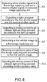
- FIG. 4 is a flowchart of the method of configuring the vehicular image pickup device according to yet another embodiment of the present disclosure
- FIG. 5 is a flowchart of an embodiment of step S 11 ;
- FIG. 6 is an image histogram of an embodiment of a first vehicle image.
- FIG. 1 is a block diagram of circuitry of a vehicular image pickup device according to an embodiment of the present disclosure.
- FIG. 2 is a flowchart of a method of configuring a vehicular image pickup device according to an embodiment of the present disclosure.
- a vehicular image pickup device 100 is adapted to be placed on a vehicle (hereinafter referred to as “the vehicle).
- the vehicular image pickup device 100 is mounted on the vehicle to capture images of a scene ahead of the vehicle, and the scene contains vehicles ahead of the vehicle.
- the vehicular image pickup device 100 includes a first image capturing unit 110 , a second image capturing unit 120 , a control module 130 and an infrared illumination module 140 .
- the first image capturing unit 110 , the second image capturing unit 120 and the infrared illumination module 140 are each signal-connected to the control module 130 .
- the first image capturing unit 110 captures images of vehicles ahead of the vehicle so as to generate a first vehicle image.
- the first vehicle image includes images of license plates of the vehicles ahead.
- the first image capturing unit 110 sends a first shutter signal while capturing images. Therefore, the first shutter signal is generated because a shutter of the first image capturing unit 110 is triggered.
- the second image capturing unit 120 captures images of vehicles ahead of the vehicle so as to generate a second vehicle image.
- the second vehicle image includes images of the vehicles ahead and the surroundings in front of the vehicles.
- the second image capturing unit 120 outputs a second shutter signal while capturing images. Therefore, the second shutter signal is generated because a shutter of the second image capturing unit 110 is triggered.
- the control module 130 is coupled to the first image capturing unit 110 and the second image capturing unit 120 .
- the control module 130 includes a logic circuit 132 .
- the logic circuit 132 detects a first shutter signal and a second shutter signal (step S 1 ) and outputs a light-up signal according to the first shutter signal and the second shutter signal (step S 3 ).
- the infrared illumination module 140 is coupled to the control module 130 .
- the infrared illumination module 140 includes a driving unit 142 and an infrared light-emitting element 144 .
- the driving unit 142 outputs a driving current to the infrared light-emitting element 144 according to the light-up signal (step S 5 ).
- the infrared light-emitting element 144 includes one or more infrared light-emitting diodes.
- the vehicular image pickup device 100 is adapted for use with a vehicle to output a driving current according to the first shutter signal of the first image capturing unit 110 and the second shutter signal of the second image capturing unit 120 so as to light up the infrared light-emitting element 144 .
- the first image capturing unit 110 is a monochrome image capturing unit.
- the first image capturing unit 110 includes a monochrome photosensing component and an infrared filtering component.
- the monochrome photosensing component captures monochrome images, and its photosensing range is of a wavelength from 400 nm to 1000 nm.
- the infrared filtering component has a photosensing wavelength of 850 ⁇ 10 nm or 940 ⁇ 10 nm.
- the infrared light-emitting element 144 has an emission wavelength of 850 ⁇ 10 nm or 940 ⁇ 10 nm.
- the license plates for example, reflect infrared light of a wavelength of 850 ⁇ 10 nm or 940 ⁇ 10 nm.
- the first image capturing unit 110 captures images of vehicles ahead of the vehicle while license plates of the vehicles ahead are exposed to irradiation of infrared light of the aforesaid wavelengths, so as to generate at the very least the first vehicle image which contains images of the license plates of the vehicles ahead.
- infrared light-emitting element 144 After the infrared light-emitting element 144 has been lit up, infrared light emitted from the infrared light-emitting element 144 reflects off the license plates and thus falls on the first image capturing unit 110 .
- the infrared filtering component allows infrared light of 850 ⁇ 10 nm or 940 ⁇ 10 nm to pass and reach the monochrome photosensing component such that the first image capturing unit 110 can capture clear images of the license plates.
- the field of view (FOV) of the first image capturing unit 110 depends on the size of the monochrome photosensing component of the first image capturing unit 110 and the focal length of the image pickup lens of the first image capturing unit 110 .
- the FOV of the first image capturing unit 110 has a field of view (horizontal) (FOV (H)) of 2.51 m and a field of view (vertical) (FOV (V)) of 1.89 m.
- the monochrome photosensing component of the first image capturing unit 110 is a photosensing coupled component (charge coupled device, CCD) or a complementary metal-oxide-semiconductor (CMOS) for generating the first vehicle image by conversion.
- the first image capturing unit 110 includes an output port for outputting the first vehicle image.
- the second image capturing unit 120 is a color image capturing unit.
- the second image capturing unit 120 includes a color photosensing component.
- the color photosensing component captures color images, and its photosensing range is of a wavelength from 400 nm to 1000 nm.
- the FOV of the second image capturing unit 120 depends on the size of the color photosensing component of the second image capturing unit 120 and the focal length of the image pickup lens of the second image capturing unit 120 .
- the FOV of the second image capturing unit 120 has an FOV (H) of 5.02 m and an FOV (V) of 3.79 m.
- the color photosensing component of the second image capturing unit 120 is a photosensing coupled component or a complementary metal-oxide-semiconductor (CMOS) for generating the second vehicle image by conversion.
- CMOS complementary metal-oxide-semiconductor
- the second image capturing unit 120 includes an output port for outputting the second vehicle image.
- the logic circuit 132 of the control module 130 includes an OR gate. Two input ends of the OR gate (the logic circuit 132 ) are coupled to the first image capturing unit 110 and the second image capturing unit 120 , respectively. The output end of the OR gate (logic circuit 132 ) is coupled to the infrared illumination module 140 . As shown in FIG. 3 , the method of configuring a vehicular image pickup device involves determining whether the first shutter signal and the second shutter signal are each a second electric potential. If the first shutter signal and/or the second shutter signal is a first electric potential, the light-up signal output from the OR gate (logic circuit 132 ) is a start signal (step S 301 ).
- the light-up signal output from the OR gate (logic circuit 132 ) is a shutdown signal (step S 303 ).
- the first electric potential is a high electric potential (or logic 1), whereas the second electric potential is a low electric potential (or logic 0).
- the logic circuit 132 is implemented as an OR gate
- the first shutter signal is a high electric potential (or logic 1)
- the second shutter signal is a high electric potential (or logic 1)
- the light-up signal output from the logic circuit 132 to the driving unit 142 of the infrared illumination module 140 is a start signal
- the start signal is a high electric potential (or logic 1).
- the driving unit 142 outputs, in response to the start signal of a high electric potential (or logic 1), a driving current to the infrared light-emitting element 144 , so as to light up the infrared light-emitting element 144 .
- the logic circuit 132 is an OR gate
- the first shutter signal is a high electric potential (or logic 1) and the second shutter signal is a low electric potential (or logic 0)
- the light-up signal output from the logic circuit 132 to the driving unit 142 of the infrared illumination module 140 is the start signal, and the start signal is a high electric potential (or logic 1).
- the driving unit 142 outputs, in response to the start signal of a high electric potential (or logic 1), a driving current to the infrared light-emitting element 144 , so as to light up the infrared light-emitting element 144 .
- the logic circuit 132 is an OR gate
- the first shutter signal is a low electric potential (or logic 0) and the second shutter signal is a high electric potential (or logic 1)
- the light-up signal output from the logic circuit 132 to the driving unit 142 of the infrared illumination module 140 is the start signal, and the start signal is a high electric potential (or logic 1).
- the driving unit 142 outputs, in response to the start signal of a high electric potential (or logic 1), a driving current to the infrared light-emitting element 144 , so as to light up the infrared light-emitting element 144 .
- the logic circuit 132 is an OR gate
- the first shutter signal is a low electric potential (or logic 0) and the second shutter signal is a low electric potential (or logic 0)
- the light-up signal output from the logic circuit 132 to the driving unit 142 of the infrared illumination module 140 is a shutdown signal
- the shutdown signal is a low electric potential (or logic 0).
- the driving unit 142 does not output, in response to the shutdown signal of a low electric potential (or logic 0), a driving current to the infrared light-emitting element 144 .
- the driving unit 142 outputs, in response to the shutdown signal of a low electric potential (or logic 0), a driving current of a current level of zero to the infrared light-emitting element 144 .
- the second image capturing unit 120 (color image capturing unit) will capture flashing images because of the lighting up of the infrared light-emitting element 144 .
- the first image capturing unit 110 (monochrome image capturing unit) and/or the second image capturing unit 120 (color image capturing unit) starts to capture images, that is, the first shutter signal and/or the second shutter signal is the first electric potential, starting the infrared light-emitting element 144 will not cause the second image capturing unit 120 (color image capturing unit) to capture flashing images.
- the infrared light-emitting element 144 is shut down, so as to not only extend the service life of the infrared illumination module 140 , but also enhance heat dissipation.
- the control module 130 further includes an adjusting unit 134 .
- the adjusting unit 134 is coupled to the first image capturing unit 110 and the driving unit 142 of the infrared illumination module 140 .
- the adjusting unit 134 receives and analyzes the first vehicle image, so as to obtain its exposure value (EV) (step S 9 ).
- the adjusting unit 134 adjusts the driving current of the infrared light-emitting element 144 according to the exposure value (step S 11 ).
- the adjusting unit 134 adjusts the driving current of the infrared light-emitting element 144 in accordance with the magnitude of the exposure value of the first vehicle image, so as to alter the brightness of the infrared light-emitting element 144 by adjusting the light emission power value of the infrared light-emitting element 144 .
- the adjusting unit 134 includes an image signal processor (ISP), but the present disclosure is not limited thereto.
- control module 130 is a microprocessor, microcontroller, digital signal processor, central processing unit (CPU), or any analog and/or digital device based on the operating command and the operating signal, but the present disclosure is not limited thereto.
- the adjusting unit 134 performs graphic recognition on the first vehicle image to calculate the brightness of all the pixels in the first vehicle image so as to obtain the exposure value thereof. In another exemplary embodiment of step S 9 , the adjusting unit 134 performs graphic recognition on the first vehicle image to calculate the brightness of the pixels in the images of the license plates attributed to the vehicles ahead and contained in the first vehicle image so as to obtain the exposure value thereof.
- the adjusting unit 134 receives and analyzes the first vehicle image to therefore convert the first vehicle image into an image histogram (step S 1101 ).
- This step entails counting the number of pixels of the same brightness in the first vehicle image to therefore convert the first vehicle image into an image histogram.
- the horizontal axis of the image histogram represents grayscale values, for example, 0 to 255, of all the pixels in the first vehicle image.
- the vertical axis of the image histogram represents pixel quantity corresponding to the grayscale values of the horizontal axis.
- the adjusting unit 134 calculates the pixel quantity of pixels with brightness greater than a brightness threshold T in the image histogram (step S 1103 ).
- the brightness threshold T is set to a predetermined grayscale value. Assuming that the brightness threshold T is a single numeric value, such as 160 , the brightness threshold T divides the horizontal axis of the image histogram into two segments.
- the adjusting unit 134 calculates the pixel quantity of the pixels with brightness greater than the brightness threshold T in the image histogram.
- the adjusting unit 134 compares the pixel quantity of the pixels having brightness greater than the brightness threshold T with a quantity threshold (step S 1105 ).
- the adjusting unit 134 determines whether the pixel quantity of the pixels having brightness greater than the brightness threshold T is greater than the quantity threshold.
- the quantity threshold is a single quantity threshold.
- the adjusting unit 134 adjusts the driving current of the infrared light-emitting element 144 such that the driving current functions as the first current, and thus the infrared illumination module 140 outputs the first current to function as the driving current of the infrared light-emitting element 144 (step S 1107 a ).
- the pixel quantity of the pixels having brightness greater than the brightness threshold T is less than the quantity threshold, it is determined that the first vehicle image has a low exposure value.
- the adjusting unit 134 adjusts the driving current of the infrared light-emitting element 144 such that the driving current functions as the second current, and thus the infrared illumination module 140 outputs the second current to function as the driving current of the infrared light-emitting element 144 (step S 1107 b ).
- the first current is weaker than the second current.
- the quantity threshold is illustrative and thus subject to changes as needed.
- the actual quantity threshold is provided in the form of a combination of two quantity thresholds (i.e., upper quantity threshold and lower quantity threshold).
- the quantity and the driving current of the results of comparison between the pixel quantity of the pixels having brightness greater than the brightness threshold and the quantity thresholds vary with the quantity thresholds. For instance, when the pixel quantity of the pixels having brightness greater than the brightness threshold is greater than the upper quantity threshold, it will be determined that the first vehicle image has a high exposure value.
- the adjusting unit 134 adjusts the driving current of the infrared light-emitting element 144 such that the driving current functions as the first current.
- the adjusting unit 134 adjusts the driving current of the infrared light-emitting element 144 such that the driving current functions as the second current.
- the pixel quantity of the pixels having brightness greater than the brightness threshold is less than the lower quantity threshold, it will be determined that the first vehicle image has a low exposure value.
- the adjusting unit 134 adjusts the driving current of the infrared light-emitting element 144 such that the driving current functions as a third current.
- the first current is weaker than the second current
- the second current is weaker than the third current.
- the first image capturing unit 110 , the second image capturing unit 120 , the control module 130 and the infrared illumination module 140 are integrated into the same image pickup system, such as an image pickup device which comes with an infrared lamp, two different image capturing units and a processor.
- a vehicular image pickup device and a method of configuring the same are adapted for use with a vehicle to light up an infrared light-emitting element according to a first shutter signal of a first image capturing unit and a second shutter signal of a second image capturing unit.
Abstract
Description
Claims (11)
Priority Applications (1)
| Application Number | Priority Date | Filing Date | Title |
|---|---|---|---|
| US16/151,667 US11012632B2 (en) | 2018-01-03 | 2018-10-04 | Vehicular image pickup device and method of configuring same |
Applications Claiming Priority (2)
| Application Number | Priority Date | Filing Date | Title |
|---|---|---|---|
| US201862613327P | 2018-01-03 | 2018-01-03 | |
| US16/151,667 US11012632B2 (en) | 2018-01-03 | 2018-10-04 | Vehicular image pickup device and method of configuring same |
Publications (2)
| Publication Number | Publication Date |
|---|---|
| US20190208104A1 US20190208104A1 (en) | 2019-07-04 |
| US11012632B2 true US11012632B2 (en) | 2021-05-18 |
Family
ID=67060056
Family Applications (1)
| Application Number | Title | Priority Date | Filing Date |
|---|---|---|---|
| US16/151,667 Active 2038-12-16 US11012632B2 (en) | 2018-01-03 | 2018-10-04 | Vehicular image pickup device and method of configuring same |
Country Status (1)
| Country | Link |
|---|---|
| US (1) | US11012632B2 (en) |
Families Citing this family (2)
| Publication number | Priority date | Publication date | Assignee | Title |
|---|---|---|---|---|
| US20210314477A1 (en) * | 2018-08-17 | 2021-10-07 | Hewlett-Packard Development Company, L.P. | Exposure control of captured images |
| JP2022025280A (en) * | 2020-07-29 | 2022-02-10 | 株式会社Jvcケンウッド | Infrared imaging apparatus and infrared imaging system |
Citations (3)
| Publication number | Priority date | Publication date | Assignee | Title |
|---|---|---|---|---|
| US20170104939A1 (en) * | 2015-10-10 | 2017-04-13 | Ambarella Shanghai Co., Ltd. | Night vision device with periodic infrared illumination and global shutter cmos sensor |
| US9623799B2 (en) * | 2002-11-14 | 2017-04-18 | Magna Electronics Inc. | Camera module for vehicle |
| US20180308282A1 (en) * | 2017-04-20 | 2018-10-25 | Denso Corporation | Shape measuring apparatus and method |
-
2018
- 2018-10-04 US US16/151,667 patent/US11012632B2/en active Active
Patent Citations (3)
| Publication number | Priority date | Publication date | Assignee | Title |
|---|---|---|---|---|
| US9623799B2 (en) * | 2002-11-14 | 2017-04-18 | Magna Electronics Inc. | Camera module for vehicle |
| US20170104939A1 (en) * | 2015-10-10 | 2017-04-13 | Ambarella Shanghai Co., Ltd. | Night vision device with periodic infrared illumination and global shutter cmos sensor |
| US20180308282A1 (en) * | 2017-04-20 | 2018-10-25 | Denso Corporation | Shape measuring apparatus and method |
Also Published As
| Publication number | Publication date |
|---|---|
| US20190208104A1 (en) | 2019-07-04 |
Similar Documents
| Publication | Publication Date | Title |
|---|---|---|
| US11758279B2 (en) | WDR imaging with LED flicker mitigation | |
| US6549239B1 (en) | Smart progressive-scan charge-coupled device camera | |
| WO1997042756A9 (en) | Smart progressive-scan charge-coupled device camera | |
| JPH1093856A (en) | Solid-state image pickup device | |
| CN112672114B (en) | Method, system, equipment and storage medium for switching day and night modes of monitoring equipment | |
| US11012632B2 (en) | Vehicular image pickup device and method of configuring same | |
| EP1883242A1 (en) | Image processor for vehicles | |
| US20050199815A1 (en) | Irradiation control device | |
| JP6149826B2 (en) | Imaging apparatus and scene determination method | |
| US11153546B2 (en) | Low-light imaging system | |
| US10864854B2 (en) | Vehicle camera device and method for setting the same | |
| JP2008230464A (en) | Automatic exposure device for on-vehicle camera | |
| CN113401048B (en) | Image capturing device for vehicle and setting method thereof | |
| JP6525723B2 (en) | Imaging device, control method therefor, program, and storage medium | |
| JP2012010282A (en) | Imaging device, exposure control method, and exposure control program | |
| KR101971535B1 (en) | Apparatus and method for adjusting auto focus in image taking device | |
| CN115150560A (en) | Light supplementing system, image acquisition system, method, equipment and storage medium | |
| JP6906084B2 (en) | Color camera device and optical parts | |
| CN110581955B (en) | Image capturing device for vehicle and setting method thereof | |
| US20150156382A1 (en) | Multi-channel glare-suppression device of a digital image system | |
| JP2007249568A (en) | Image processor and image processing method, recording medium and program | |
| KR100536988B1 (en) | Flash light adjustment apparatus in using image sensor | |
| KR20110055195A (en) | Apparatus and method for controlling flash | |
| JPH0470276A (en) | Camera | |
| KR20120117155A (en) | Video camera with adjustable brightness of light and method for adjusting of the same |
Legal Events
| Date | Code | Title | Description |
|---|---|---|---|
| FEPP | Fee payment procedure |
Free format text: ENTITY STATUS SET TO UNDISCOUNTED (ORIGINAL EVENT CODE: BIG.); ENTITY STATUS OF PATENT OWNER: LARGE ENTITY |
|
| AS | Assignment |
Owner name: GETAC TECHNOLOGY CORPORATION, TAIWAN Free format text: ASSIGNMENT OF ASSIGNORS INTEREST;ASSIGNOR:CHEN, MIN-TAI;REEL/FRAME:047179/0434 Effective date: 20180920 |
|
| STPP | Information on status: patent application and granting procedure in general |
Free format text: DOCKETED NEW CASE - READY FOR EXAMINATION |
|
| STPP | Information on status: patent application and granting procedure in general |
Free format text: NON FINAL ACTION MAILED |
|
| STPP | Information on status: patent application and granting procedure in general |
Free format text: RESPONSE TO NON-FINAL OFFICE ACTION ENTERED AND FORWARDED TO EXAMINER |
|
| STPP | Information on status: patent application and granting procedure in general |
Free format text: FINAL REJECTION MAILED |
|
| STPP | Information on status: patent application and granting procedure in general |
Free format text: NON FINAL ACTION MAILED |
|
| STPP | Information on status: patent application and granting procedure in general |
Free format text: RESPONSE TO NON-FINAL OFFICE ACTION ENTERED AND FORWARDED TO EXAMINER |
|
| STPP | Information on status: patent application and granting procedure in general |
Free format text: NOTICE OF ALLOWANCE MAILED -- APPLICATION RECEIVED IN OFFICE OF PUBLICATIONS |
|
| STPP | Information on status: patent application and granting procedure in general |
Free format text: PUBLICATIONS -- ISSUE FEE PAYMENT RECEIVED |
|
| STPP | Information on status: patent application and granting procedure in general |
Free format text: PUBLICATIONS -- ISSUE FEE PAYMENT VERIFIED |
|
| STCF | Information on status: patent grant |
Free format text: PATENTED CASE |