US11007666B2 - Cutting machine - Google Patents
Cutting machine Download PDFInfo
- Publication number
- US11007666B2 US11007666B2 US16/874,487 US202016874487A US11007666B2 US 11007666 B2 US11007666 B2 US 11007666B2 US 202016874487 A US202016874487 A US 202016874487A US 11007666 B2 US11007666 B2 US 11007666B2
- Authority
- US
- United States
- Prior art keywords
- cutting
- cutter
- cut
- blade
- cutting line
- Prior art date
- Legal status (The legal status is an assumption and is not a legal conclusion. Google has not performed a legal analysis and makes no representation as to the accuracy of the status listed.)
- Active
Links
Images


Classifications
-
- B—PERFORMING OPERATIONS; TRANSPORTING
- B26—HAND CUTTING TOOLS; CUTTING; SEVERING
- B26F—PERFORATING; PUNCHING; CUTTING-OUT; STAMPING-OUT; SEVERING BY MEANS OTHER THAN CUTTING
- B26F1/00—Perforating; Punching; Cutting-out; Stamping-out; Apparatus therefor
- B26F1/0092—Perforating means specially adapted for printing machines
-
- B—PERFORMING OPERATIONS; TRANSPORTING
- B26—HAND CUTTING TOOLS; CUTTING; SEVERING
- B26D—CUTTING; DETAILS COMMON TO MACHINES FOR PERFORATING, PUNCHING, CUTTING-OUT, STAMPING-OUT OR SEVERING
- B26D5/00—Arrangements for operating and controlling machines or devices for cutting, cutting-out, stamping-out, punching, perforating, or severing by means other than cutting
- B26D5/005—Computer numerical control means
-
- B—PERFORMING OPERATIONS; TRANSPORTING
- B26—HAND CUTTING TOOLS; CUTTING; SEVERING
- B26D—CUTTING; DETAILS COMMON TO MACHINES FOR PERFORATING, PUNCHING, CUTTING-OUT, STAMPING-OUT OR SEVERING
- B26D7/00—Details of apparatus for cutting, cutting-out, stamping-out, punching, perforating, or severing by means other than cutting
- B26D7/26—Means for mounting or adjusting the cutting member; Means for adjusting the stroke of the cutting member
-
- B—PERFORMING OPERATIONS; TRANSPORTING
- B26—HAND CUTTING TOOLS; CUTTING; SEVERING
- B26F—PERFORATING; PUNCHING; CUTTING-OUT; STAMPING-OUT; SEVERING BY MEANS OTHER THAN CUTTING
- B26F1/00—Perforating; Punching; Cutting-out; Stamping-out; Apparatus therefor
- B26F1/38—Cutting-out; Stamping-out
- B26F1/3806—Cutting-out; Stamping-out wherein relative movements of tool head and work during cutting have a component tangential to the work surface
- B26F1/3813—Cutting-out; Stamping-out wherein relative movements of tool head and work during cutting have a component tangential to the work surface wherein the tool head is moved in a plane parallel to the work in a coordinate system fixed with respect to the work
-
- B—PERFORMING OPERATIONS; TRANSPORTING
- B41—PRINTING; LINING MACHINES; TYPEWRITERS; STAMPS
- B41J—TYPEWRITERS; SELECTIVE PRINTING MECHANISMS, i.e. MECHANISMS PRINTING OTHERWISE THAN FROM A FORME; CORRECTION OF TYPOGRAPHICAL ERRORS
- B41J11/00—Devices or arrangements of selective printing mechanisms, e.g. ink-jet printers or thermal printers, for supporting or handling copy material in sheet or web form
- B41J11/66—Applications of cutting devices
- B41J11/70—Applications of cutting devices cutting perpendicular to the direction of paper feed
- B41J11/706—Applications of cutting devices cutting perpendicular to the direction of paper feed using a cutting tool mounted on a reciprocating carrier
-
- B—PERFORMING OPERATIONS; TRANSPORTING
- B26—HAND CUTTING TOOLS; CUTTING; SEVERING
- B26D—CUTTING; DETAILS COMMON TO MACHINES FOR PERFORATING, PUNCHING, CUTTING-OUT, STAMPING-OUT OR SEVERING
- B26D5/00—Arrangements for operating and controlling machines or devices for cutting, cutting-out, stamping-out, punching, perforating, or severing by means other than cutting
Definitions
- the present inventions relate to cutting machines.
- Japanese Unexamined Patent Application Publication 1990-262995 discloses a method for controlling a blade of a cutting machine wherein, when changing the direction of the cutting blade, the cutting blade is first lifted away from the material being cut, and moved to the starting position for the next cut prior to execution of the next cutting operation in a different direction.
- Japanese Unexamined Patent Application Publication 1995-39229 discloses a cutter which performs a so-called “perforation cut,” wherein perforations are formed along a line for making a sheet material tearable.
- the perforations are formed in a sheet material by reducing, for a brief interval or regular time intervals, the tool pressure of a cutter that is pressed against the sheet, to produce a state wherein the cutter rides over the sheet surface or moves partially within the sheet.
- Cutting machines disclosed herein can comprise a supporting platform, a cutter, a cutter carriage, a moving mechanism, and a controlling device.
- the cutter can have a shaft and a blade that is formed at a tip end of the shaft.
- the cutter carriage can have a holding portion for holding the shaft of the cutter so as to enable rotation.
- the moving mechanism can be a mechanism for moving the cutter carriage relative to the supporting platform.
- the controlling device can be configured so that the following processes (a) through (c) are executed:
- Such a cutting machine can create a sharper, cleaner corner portion where a cutting line includes a corner.
- FIG. 1 is a front view depicting a structure for a cutting machine 100 .
- FIG. 2 is a front view of a cutter 20 .
- FIG. 3 is a perspective diagram depicting the driving part of a cutter carriage 30 that is driven by a solenoid 32 .
- FIG. 4 is a circuit diagram depicting an example of a circuit for controlling the solenoid 32 .
- FIG. 5 is a block diagram of a controlling device 50 .
- FIG. 6 is a schematic diagram depicting cutting lines S 1 through S 5 that are set for the cutting material 200 .
- FIG. 7 is a schematic diagram depicting a step (first step) for cutting the cutting material 200 along one cutting line Sc 21 that ends at a corner portion Sc 2 .
- FIG. 8 is a schematic diagram depicting a step (second step) for lifting a tip end 22 a of a blade 22 of the cutter 20 from the cutting material 200 .
- FIG. 9 is a schematic diagram depicting a step (third step) for causing the blade of the cutter 20 to contact the cutting material 200 , facing the other cutting line Sc 22 of the corner portion Sc 2 .
- FIG. 10 is a schematic diagram depicting an example of a blade turning path Sd 1 that is set at the corner portion Sc 1 , in the corner portion Sc depicted in FIG. 6 .
- FIG. 11 is a schematic diagram depicting an example of cutting of the corner portion Sc 1 .
- FIG. 12 is a schematic diagram depicting an example of cutting up the corner portion Sc 1 .
- FIG. 13 is a schematic diagram depicting an example of cutting up the corner portion Sc 1 .
- FIG. 14 is a schematic diagram depicting an example of cutting up the corner portion Sc 1 .
- FIG. 15 is a schematic diagram depicting a pattern for the position of the blade 22 when a material with a seal is adhered onto a backing sheet is the cutting material 200 .
- FIG. 16A is a diagram depicting a mode of cutting when cutting the cutting material along a cutting line that has a corner portion.
- FIG. 16B is a diagram depicting another mode of cutting when cutting the cutting material along a cutting line that has a corner portion.
- FIG. 16C is a diagram depicting yet another mode of cutting when cutting the cutting material along a cutting line that has a corner portion.
- FIG. 17A is a diagram depicting the state wherein a corner portion the cutting material, cut in the mode of cutting depicted in FIG. 16A , is bent upward.
- FIG. 17B is a diagram depicting the state wherein a tip of the corner portion of the cutting material, cut in the mode of cutting depicted in FIG. 16B , is torn.
- FIG. 17C is a diagram depicting the state wherein the corner portion of the cutting material, cut in the mode of cutting depicted in FIG. 16C , is pulled apart.
- FIG. 1 is a front view depicting a structure for the cutting machine 100 .
- the cutting machine 100 comprises a supporting platform 10 , a cutter 20 , a cutter carriage 30 , a moving mechanism 40 , and a controlling device 50 .
- the cutter carriage 30 is depicted in a state wherein the cover on the front face thereof is removed, to reveal the internal structure thereof.
- the supporting platform 10 is a member on which the cutting material is placed.
- the supporting platform 10 has, for example, a supporting face 11 on which is placed the material that is to be cut, which can be a sheet material.
- the cutter 20 is a member for cutting the material that is to be cut.
- FIG. 2 is a front view of the cutter 20 .
- the cutter 20 has a shaft 21 and a blade 22 that is formed on the tip end of the shaft 21 .
- the cutter 20 can be referred to as a cutter blade assembly 20 .
- the tip end 22 a of the blade 22 is offset with respect to a centerline X 1 of the shaft 21 of the cutter 20 .
- the distance with which the tip end 22 a of the blade 22 is offset in respect to the centerline X 1 of the shaft 21 of the cutter 20 shall be termed the “offset distance X 2 .”
- the cutter carriage 30 comprises a holding portion 31 and a solenoid 32 .
- FIG. 3 is a perspective diagram depicting the driven part of the cutter carriage 30 that is driven by the solenoid 32 .
- the holding portion 31 is a part that holds the shaft 21 of the cutter 20 so as to enable rotation.
- a chuck 31 a for example, that holds the shaft 21 of the cutter 20 , may be held by a bearing 31 b .
- the shaft 21 of the cutter 20 is supported by the chuck 31 a and the bearing 31 b so as to enable rotation of the shaft 21 about the centerline X 1 ( FIG. 2 ).
- the structure is such that the chuck 31 a is opened and closed through rotating an operating screw 31 c , to attach or remove the cutter 20 .
- the structure is such that the chuck 31 a and bearing 31 b are removed from the cutter carriage 30 through rotating the operating screw 31 d .
- the shaft 21 of the cutter 20 is supported in a state wherein the blade 22 of the cutter 20 protrudes from the bottom of the chuck 31 a.
- FIG. 1 through FIG. 3 may be referenced regarding the cutting machine 100 and the cutting material 200 , even if not referenced explicitly.
- the solenoid 32 is structured so as to support the holding portion 31 , and so as to raise and lower the holding portion 31 in the cutter carriage 30 .
- the cutter carriage 30 is disposed so that a lower portion of the cutter carriage 30 faces the supporting face 11 of the supporting platform 10 whereon the cutting material 200 is supported.
- the blade 22 of the cutter 20 which protrudes to one side of the holding portion 31 , faces the supporting face 11 of the supporting platform 10 .
- the direction that approaches the supporting face 11 is termed arbitrarily “down,” and the direction away from the supporting face 11 is termed arbitrarily “up.”
- the solenoid 32 has a bobbin 32 a onto which a coil is wound, and a movable core 32 b (plunger) that is inserted into the bobbin 32 a .
- the stroke direction of the movable core 32 b is oriented in the direction that is perpendicular to the supporting platform 10 .
- an arm 32 c is attached to the movable core 32 b .
- the arm 32 c extends downward, on the outside of the bobbin 32 a , from the top end of the movable core 32 b .
- a clamp 32 d for gripping the bearing 31 b of the holding portion 31 , is attached to the bottom end portion of the arm 32 c.
- FIG. 4 is a circuit diagram depicting an example of a circuit for controlling the solenoid 32 .
- the holding portion 31 is pushed downward in the cutter carriage 30 .
- the holding portion 31 is lifted upward in the cutter carriage 30 .
- the structure is such that the holding portion 31 can be raised and lowered relative to the supporting platform 10 through the solenoid 32 .
- the cutter carriage 30 further comprises a spring 33 , a shock absorbing material 34 , and a first substrate 35 on which is mounted circuitry for operating the solenoid 32 .
- the electric circuit depicted in FIG. 4 is mounted on the first substrate 35 .
- the spring 33 is attached in a state that is tensioned between the arm 32 c that supports the holding portion 31 , and an upper portion of the case of the cutter carriage 30 , as depicted in FIG. 1 and FIG. 3 , and applies the a force in the direction of lifting the holding portion 31 upwardly, thereby biasing the holding portion 31 towards an upward position. Because of this, when the arm 32 c is pushed downward by the solenoid 32 , the arm 32 c is pressed downward against the reactive force of the spring 33 .
- the arm 32 c is pushed upward by the solenoid 32 , the arm 32 c is pulled upward, assisted by the reaction force of the spring 33 .
- the holding portion 31 is pulled up smoothly, assisted by the reaction force of the spring 33 , even if the blade 22 of the cutter 20 , which is attached to the holding portion 31 , is wedged into the cutting material 200 .
- the holding portion 31 will be held in a state wherein it is pulled up to a position away from the cutting material 200 .
- the shock absorbing material 34 is disposed above the arm 32 c .
- the shock absorbing material 34 may be, for example, rubber.
- the shock absorbing material 34 is attached to a member that is disposed above the arm 32 c , to mitigate the noise that is produced when the arm 32 c strikes the member that is disposed thereabove.
- the arm 32 c is pulled upward, through the effect of the spring 33 , to a position wherein it strikes the shock absorbing material 34 .
- the moving mechanism 40 is a mechanism that can be configured to move the cutter carriage 30 relative to the supporting platform 10 .
- the cutter carriage 30 may be supported in respect to the supporting platform 10 so that the shaft 21 of the cutter 20 will face a direction that is perpendicular to the flat face of the supporting platform 10 .
- the moving mechanism 40 can be structured so as to move the cutter carriage 30 to an appropriate position with respect to an XY coordinate system that is set parallel to the flat portion of the stationary supporting platform 10 onto which the cutting material 200 is placed.
- a first mechanism is configured to move the cutter carriage 30 in the X direction
- a second mechanism is configured to move the cutter carriage 30 in the Y direction.
- the first and second mechanisms can be combined together.
- the cutter carriage 30 can be attached to a first guide shaft that is disposed along the X direction.
- the first mechanism can be attached to a second guide shaft that is disposed along the Y direction.
- the configuration may be such that the cutter carriage 30 is moved also in respect to a Z-axis that is perpendicular to the flat portion whereon the cutting material 200 is placed.
- the moving mechanism 40 is not limited to the form described above.
- the moving mechanism 40 can instead be a mechanism wherein the supporting platform 10 is moved relative to the cutter carriage 30 .
- it can instead be a mechanism for moving both the cutter carriage 30 and the supporting platform 10 .
- it may be a mechanism for moving the cutter carriage 30 in one or two of the directions of an XYZ coordinate system, and for moving the supporting platform 10 in the other direction or directions.
- an orthogonal coordinate system is presented as an example, the movement need not necessarily be along an orthogonal coordinate system. Other coordinate systems can also be used.
- FIG. 5 is a block diagram of controlling device 50 .
- the controlling device 50 as depicted in FIG. 5 , comprises a first setting portion 50 a 1 , a second setting portion 50 a 2 , a first storing portion 50 b 1 , a second storing portion 50 b 2 , and a cut processing portion 70 .
- the controlling device 50 is a device configured to control the solenoid 32 of the cutter carriage 30 , the moving mechanism 40 , and the like, and for controlling the various processes of the cutting machine 100 .
- the controlling device 50 can be embodied in, for example, a computer that is operated according to a program that has been established in advance.
- the various functions of the controlling device 50 can be processed through various calculating devices of a computer (also known as a “processors,” “CPUs” (Central Processing Units) or “MPUs” (Micro Processing Units)), and storing devices (memories, hard disks, and the like), that define structures within the controlling device 50 , in cooperation with software.
- a computer also known as a “processors,” “CPUs” (Central Processing Units) or “MPUs” (Micro Processing Units)
- storing devices memory, hard disks, and the like
- each of the structures and processes of the controlling device 50 may be embodied in a whole or in part by databases and data structures that store, in a predetermined form, data that is embodied by the computer, processing modules that carry out prescribed calculation processes following programs that have been established in advance, and the like.
- the controlling device 50 can also be referred to as a “controller”.
- the first setting portion 50 a 1 can be programmed so as to set cutting lines S 1 through S 5 with respect to the cutting material 200 that is placed on the supporting platform 10 .
- FIG. 6 is a schematic diagram depicting the cutting lines S 1 through S 5 that are set for the cutting material 200 .
- the cutting lines S 1 through S 5 are set for the cutting material 200 .
- the cutting line S 1 is set so as to encompass a rectangular region A 1 along an outer frame of the rectangular cutting material 200 .
- the cutting lines S 2 through S 5 are set so as to encompass a plurality of triangular regions A 2 through A 5 , respectively, within the rectangular region A 1 that is encompassed by the cutting line S 1 .
- the cutting line S 1 that encompasses the rectangular region A 1 and the cutting lines S 2 through S 5 that encompassed the triangular regions A 2 through A 5 have corner portions Sc wherein the directions of each of the cutting lines S 2 through S 5 change.
- the cutting lines S 1 through S 5 can each be set as paths for the shaft 21 of the cutter 20 , in instructions for the cutter carriage 30 , for example.
- the tip end 22 a of the blade 22 of the cutter 20 is offset from the centerline X 1 of the shaft 21 of the cutter 20 .
- the holding portion 31 supports the shaft 21 of the cutter 20 so as to enable rotation.
- the shaft 21 of the cutter 20 rotates so that the tip end 22 a of the blade 22 of the cutter 20 will be to the rear of the shaft 21 of the cutter 20 .
- the blade 22 of the cutter 20 will face the direction of forward movement. Additionally, the tip end 22 a of the blade 22 of the cutter 20 will follow behind the shaft 21 of the cutter 20 , along the cutting line S 1 to S 5 .
- the position wherein the tip end 22 a of the blade 22 contacts the cutting material 200 may be calculated from the position of the shaft 21 of the cutter 20 . That is, the tip end 22 a of the blade 22 will be to the rear of the centerline X 1 of the shaft 21 of the cutter 20 , in the direction of forward movement of the blade 22 of the cutter 20 , by the offset distance (offset distance X 2 ) of the tip end 22 a of the blade 22 .
- the controlling device 50 can store the offset distance X 2 of the cutter 20 in advance.
- the position of the tip end 22 a of the blade 22 is calculated depending on this offset distance X 2 . This enables control of the position at which the blade 22 of the cutter 20 contacts the cutting material 200 .
- the cut processing portion 70 can be programmed so as to cut the cutting material along the cutting lines.
- the cut processing portion 70 comprises a first processing portion 71 , a second processing portion 72 , a third processing portion 73 , and a fourth processing portion 74 .
- the first processing portion 71 can be structured so that a first step will be executed. If the cutting line S 1 through S 5 has at least one corner portion Sc wherein the direction changes, the first step can be a step for moving the blade 22 of the cutter 20 along one cutting line that arrives (or “ends”) at the corner portion Sc. In this first step, the blade 22 of the cutter 20 is pressed against the cutting material 200 , at at least a portion of one cutting line that arrives at the corner portion Sc, with a force that is set in advance so that the cutting material 200 will be cut.
- the second processing portion 72 can be structured so as to execute a second step.
- the second step can be a step for lifting the tip end 22 a of the blade 22 of the cutter 20 away from the cutting material 200 , after the first step.
- the tip end 22 a of the blade 22 of the cutter 20 can be lifted away from the cutting material 200 , that is, the tip end 22 a of the blade 22 of the cutter 20 being separated from the cutting material 200 .
- the contact between the cutter 20 and the cutting material 200 can be suspended, temporarily.
- the shaft 21 of the cutter 20 becomes free to move in any direction with the holding portion 31 .
- the tip end 22 a of the blade 22 of the cutter 20 would normally be separated or spaced from the cutting material 200 .
- the tip end 22 a of the blade 22 of the cutter 20 can become wedged in the cutting material 200 .
- a small frictional force may act between the tip end 22 a of the blade 22 of the cutter 20 and the cutting material 200 .
- the cutting material 200 can be pulled upwardly together with the tip end 22 a of the blade 22 that is pulled up, so that the cutter 20 and the cutting material 200 remain in contact.
- the structure is such that, in the second step, the cutter 20 is held for a predetermined time interval, in a state wherein it is lifted from the cutting material 200 . Maintaining the state wherein the cutter 20 is lifted from the cutting material 200 enables the cutter 20 to be separated more reliably from the cutting material 200 despite the presence of a frictional force between the cutter 20 and the cutting material 200 .
- the time interval during which the state wherein the cutter 20 is lifted from the cutting material 200 can be, for example, 10 ms or more. This time is not limited thereto, but can be, for example, 20 ms or more. In other embodiments, this time can be set to 50 ms or more. Note that the time interval during which the cutter 20 is lifted from the cutting material 200 is maintained can be set to a time that can sufficiently reliably separate the cutter 20 from the cutting material 200 . The longer the time interval during which the state wherein the cutter 20 is lifted from the cutting material 200 is maintained, the longer the cycle time for cutting the cutting material 200 . Because of this, the time interval during which the state wherein the cutter 20 is lifted from the cutting material 200 is maintained need not be set to a time that is longer than necessary.
- the time interval during which the state wherein the cutter 20 is lifted from the cutting material 200 is maintained can be set to an appropriate time determined by carrying out testing in advance.
- the configuration may be such that the time interval that is set in advance in the second step can be set by a user.
- the time interval during which the cutter 20 is lifted from the cutting material 200 is maintained may differ depending on the frictional force that acts between the cutter 20 and the cutting material 200 .
- the separation of the cutter 20 from the cutting material 200 can be set more reliably through the time being set appropriately by the user.
- the cutting machine 100 can be provided with a detecting portion for detecting whether or not the cutter 20 has been separated from the cutting material 200 .
- This detecting portion can comprise a distance measuring sensor provided on the cutter carriage 30 , configured to measure the distance between the cutter carriage 30 and the cutting material 200 .
- the output of the sensor can used as an indication of whether or not the cutting material 200 has been pulled up together with the cutter 20 .
- the cutting material 200 being pulled up together with the cutter 20 may be detected instead based on an image captured by a camera that can be provided on the cutter carriage 30 .
- Whether or not the cutter 20 has been separated from the cutting material 200 can instead be detected by detecting the reaction force received from the shaft 21 of the cutter 20 in the holding portion 31 that holds the shaft 21 of the cutter 20 .
- the third processing portion 73 is structured so as to execute a third step.
- the third step can be a step wherein the blade of the cutter 20 is brought into contact with the cutting material 200 with a force that has been set in advance so that the cutting material 200 will not be cut, and is caused to face along the other cutting line of the corner portion Sc, following the second step. Because contact between the cutter 20 and the cutting material 200 was temporarily suspended in the second step, in the third step the blade 22 of the cutter 20 can be directed along the other cutting line of the corner portion Sc smoothly.
- the fourth processing portion 74 can be structured so as to execute a fourth step.
- the fourth step can be a step for causing the blade 22 of the cutter 20 to press against the cutting material 200 with a force that has been set in advance, and moving along the other cutting line of the corner portion Sc so that the cutting material 200 will be cut at at least a portion of the other cutting line of the corner portion Sc, after the third step.
- the cutting material 200 can be cut along the other cutting line of the corner portion Sc by the blade 22 of the cutter 20 .
- the tip end 22 a of the blade 22 is offset from the shaft 21 , as depicted in FIG. 2 .
- the cutter 20 can be operated in a state wherein the shaft 21 is supported so as to enable rotation.
- a cutting operation using the blade 22 of the cutter 20 to cut the cutting material 200 along a corner portion Sc 2 (referencing FIG. 6 ) wherein the cutting line S 1 bends at a right angle from one cutting line Sc 21 toward the other cutting line Sc 22 is explained below, as an example.
- FIG. 7 is a schematic diagram depicting a step (first step) for cutting the cutting material 200 along one cutting line Sc 21 that arrives at the corner portion Sc 2 .
- FIG. 8 is a schematic diagram depicting a step (second step) for lifting the tip end 22 a of the blade 22 of the cutter 20 up from the cutting material 200 .
- FIG. 9 is a schematic diagram depicting a step (third step) for causing the blade of the cutter 20 to come into contact with the cutting material 200 , and to face the other cutting line of the corner portion Sc 2 .
- FIG. 7 through FIG. 9 show, with virtual lines, a state wherein the cutter 20 is laying over the cutting material 200 so that the shaft 21 of the cutter 20 will be perpendicular to the cutting line Sc 21 .
- the blade 22 of the cutter 20 is moved, in the first step, along one cutting line Sc 21 that arrives at the corner portion Sc 2 .
- the tip end 22 a of the blade 22 of the cutter 20 will be positioned to the rear of the shaft 21 of the cutter 20 , in terms of the direction of forward motion of the blade 22 .
- the tip end 22 a of the blade 22 of the cutter 20 is pressed against the cutting material 200 with a force that is set in advance so that the cutting material 200 will be cut.
- the first step ends when the tip end 22 a of the blade 22 of the cutter 20 has arrived at the corner portion Sc 2 , as depicted in FIG. 8 .
- the centerline X 1 of the shaft 21 of the cutter 20 has moved beyond the cutting line Sc 22 , by the offset distance X 2 of the blade 22 of the cutter 20 , along the cutting line Sc 21 .
- the tip end 22 a of the blade 22 of the cutter 20 is lifted from the cutting material 200 .
- the blade of the cutter 20 is caused to contact the cutting material 200 with a force that is set in advance so that the cutting material 200 will not be cut.
- the centerline X 1 of the shaft 21 of the cutter 20 has overshot, by the offset distance X 2 of the blade 22 of the cutter 20 , along the cutting line Sc 21 .
- the blade of the cutter 20 is caused to contact the cutting material 200 , from the state wherein the tip end 22 a of the blade 22 of the cutter 20 had been lifted from the cutting material 200 .
- the force with which the tip end 22 a of the blade 22 of the cutter 20 contacts the cutting material 200 is a force that is set in advance so that the cutting material 200 will not be cut.
- the blade 22 of the cutter 20 is caused to face the other cutting line Sc 22 of the corner portion Sc 2 in a state where, in this way, the tip end 22 a of the blade 22 of the cutter 20 is in contact with the cutting material 200 .
- the centerline X 1 of the shaft 21 of the cutter 20 is moved so as to describe an arc, while the tip end 22 a of the blade 22 remains over the corner portion Sc 2 , in accordance with the offset distance X 2 of the blade 22 of the cutter 20 .
- the centerline X 1 of the shaft 21 of the cutter 20 is moved to a position that is advanced, from the corner portion Sc 2 , along the cutting line Sc 22 by the offset distance X 2 of the blade 22 of the cutter 20 .
- the blade 22 of the cutter 20 faces the other cutting line Sc 22 of the corner portion Sc 2 .
- the blade 22 of the cutter 20 can be pressed against the cutting material 200 with a force that is set in advance so that the cutting material 200 will be cut, and then moved along the other cutting line of the corner portion Sc 2 .
- the blade 22 of the cutter 20 is pressed against the cutting material 200 with a force that is set in advance so that the cutting material 200 will be cut, and moved along one cutting line Sc 21 that arrives at the corner portion Sc 2 .
- the blade 22 of the cutter 20 is lifted from the cutting material 200 , to be separated from the cutting material 200 , causing the shaft 21 of the cutter 20 to be free.
- the blade 22 of the cutter 20 is caused to contact the cutting material 200 with a force that is set in advance so that the cutting material 200 will not be cut. Following this, the blade of the cutter 20 is caused to face the other cutting line Sc 22 of the corner portion Sc 2 .
- the blade 22 is faced smoothly in the direction along the other cutting line Sc 22 of the corner portion Sc 2 .
- the fourth step is executed thereafter.
- the blade 22 of the cutter 20 is pressed against the cutting material 200 with a force that is set in advance so that the cutting material 200 will be cut, and moved along the other cutting line Sc 22 of the corner portion Sc 2 .
- the corner portion Sc 2 of the cutting material 200 will be cut cleanly along the cutting lines Sc 21 and Sc 22 .
- first step and the fourth step may be structured so that die cuts and half cuts are repeated sequentially.
- a “die cut” is a process wherein the blade 22 of the cutter 20 is caused to contact the cutting material 200 with a force that is set in advance so that the cutting material 200 will be cut fully through the thickness of the material 200 or through only a predetermined number of distinct layers of the sheet material, for example, cuts that define intended contours of the edges of one, a plurality, or all of the layers of the sheet material 200 .
- a “half cut” or “superficial cut” is a process wherein the blade of the cutter 20 is caused to contact the outer surface of the cutting material 200 with a force that is set in advance so that the cutting material 200 will not be cut completely through the full thickness of the material 200 or any layer of the material 200 , thereby either not cutting at all or only superficially cutting the outer surface of the material 200 . That is, in a “die cut” the cutting material 200 is cut. In contrast, the cutting material 200 is not cut in a “half cut.”
- the first step and the fourth step may be configured so that perforations are formed in the cutting material 200 along the cutting line. That is, when the cutting lines S 1 through S 5 form a closed region, as depicted in FIG. 6 , if the cutting material 200 were cut completely along the cutting lines S 1 through S 5 , then the cutting material 200 would shift at the positions that were cut completely. With perforations, on the other hand, some portions will be connected, enabling cutting of the cutting material 200 all the way to the end, even in the closed regions.
- the positions that are connected in the perforations should be set to lengths that can be torn or cut easily, after cutting, through, for example, pulling on the cut material 200 or pressing lightly with a cutter.
- the places wherein the cutting material 200 is not cut, through the half cuts should be set so as to be adequately short when compared to the places wherein the cutting material 200 is cut by the die cuts.
- the lengths of the places that are not cut, through the half cuts may be about 1/10, or more preferably, 1/50, or even more preferably 1/100 the lengths of the places in the cutting material 200 that are cut through die cuts (die cut length).
- die cut length For example, if the die cut length is 50 mm, the half cut length may be 0.5 mm.
- the configuration may be such that the user is able to set appropriate lengths for the die cut length and the half cut length.
- the first storing portion 50 b 1 of the controlling device 50 stores the force that is set in advance so that the cutting material 200 will be cut.
- the force that is set in advance so that the cutting material 200 will be cut may be, for example, stored in advance in the first storing portion 50 b 1 .
- a plurality of forces, set in advance so that the cutting material 200 will be cut, depending on the cutting material 200 , the cutter 20 , and conditions such as the temperature, may be stored in the first storing portion 50 b 1 in advance.
- the configuration may be such that the force that is set in advance so that the cutting material 200 will be cut may be set as appropriate by a user depending on the cutting material 200 , the cutter 20 , and conditions such as the temperature.
- the force that is set in advance so that the cutting material 200 will be cut may be termed the “die-cut pressure” arbitrarily.
- the second storing portion 50 b 2 stores a force that is set in advance so that the cutting material 200 will not be cut.
- the force that is set in advance so that the cutting material 200 will not be cut may be, for example, stored in advance in the second storing portion 50 b 2 .
- a plurality of forces, set in advance so that the cutting material 200 will not be cut, depending on the cutting material 200 , the cutter 20 , and conditions such as the temperature, may be stored in the second storing portion 50 b 2 in advance.
- the configuration may be such that the force that is set in advance so that the cutting material 200 will not be cut may be set as appropriate by a user depending on the cutting material 200 , the cutter 20 , and conditions such as the temperature. Note that the force that is set in advance so that the cutting material 200 will not be cut may be termed the “half-cut pressure” arbitrarily.
- the force that is set in advance so that the cutting material 200 will be cut may be determined depending on the cutting material 200 .
- the cutting material 200 may be a backing sheet with a seal affixed thereto.
- a first force that is set so as to cut only the seal that is affixed to the backing sheet, and a second force that is set so as to cut, for the individual backing sheet, the backing sheet to which the seal is affixed may be set as respective forces that are set in advance so that the cutting material 200 will be cut.
- the first force and the second force may be selected as appropriate following a program that is established in advance. This enables the seal to be cut alone, or to be cut together with the backing sheet.
- the second step for lifting the blade of the cutter 20 from the cutting material 200 , should be performed at the corner portion Sc 1 , Sc 2 .
- the force that is set in advance so that the cutting material 200 will be cut may be set with a plurality of forces. This enables cutting the cutting material 200 appropriately, depending on a variety of cutting materials 200 .
- the controlling device 50 has a second setting portion 50 a 2 , as depicted in FIG. 5 .
- FIG. 10 is a schematic diagram depicting an example of a blade turning path Sd 1 that is set at the corner portion Sc 1 of the corner portion Sc depicted in FIG. 6 .
- the arrow SS 1 indicates the direction of movement of the blade 22 of the cutter 20 in the first step, described below.
- the arrow SS 3 indicates the direction of movement of the blade 22 of the cutter 20 in the third step.
- the arrow SS 4 shows the direction of movement of the blade 22 of the cutter 20 in the fourth step.
- the arrows SS 1 , SS 3 , and SS 4 in FIG. 11 through FIG. 13 , described below.
- the second setting portion 50 a 2 is programmed so that when there is one or more corner portions Sc 1 wherein there is a change in direction of a cutting line S 1 , one cutting line Sc 11 , and another cutting line Sc 12 , which intersect at the corner portion Sc 1 , and a blade turning path Sd 1 , made from a curve connecting these cutting lines, will be set in the vicinity of the corner portion Sc 1 .
- the second setting portion 50 a 2 should be programmed in advance so as to set the blade turning path Sd 1 , made from an appropriate curve, depending on the angle of change between the one cutting line Sc 11 and the other cutting line Sc 12 that intersect at the corner portion Sc 1 , for example.
- the blade turning path Sd 1 should be a curve that is appropriate for changing the direction of the blade 22 of the cutter 20 .
- the configuration can be such that, after the second step, when the blade turning path Sd 1 is set in this way, then in the third step by the cut processing portion 70 , the blade 20 of the cutter is caused to contact the cutting material 200 with a force that has been set in advance so that the cutting material 200 will not be cut, and is moved so as to arrive at the other cutting line Sc 12 of the corner portion Sc 1 following the blade turning path Sd 1 .
- the blade turning path Sd 1 is depicted by a dotted line.
- the blade turning path Sd 1 describes an arc that connects one cutting line Sc 11 and the other cutting line Sc 12 of a corner portion Sc 1 , in the respective tangent line directions thereof.
- the radius of curvature of the arc of the blade turning path Sd 1 should be set to a radius so that the tip end 22 a of the blade 22 of the cutter 20 will follow smoothly in the blade turning process, following the blade turning path Sd 1 .
- the blade turning path Sd 1 should be a path such that the tip end 22 a of the blade 22 of the cutter 20 follows smoothly in the blade turning process, to change the direction from the one cutting line Sc 11 to the other cutting line Sc 12 of the corner portion Sc 1 . From this perspective, the blade turning path Sd 1 should be set to a curve that connects smoothly the one cutting line Sc 11 and the other cutting line Sc 12 of the corner portion Sc 1 .
- the blade turning path Sd 1 is not limited to the shape depicted in FIG. 10 .
- the first processing portion 71 is structured so as to execute the first step for pressing the blade 22 of the cutter 20 against the cutting material 200 with the force that has been set in advance so that the cutting material 200 will be cut, and moving the blade 22 of the cutter 20 along the one cutting line Sc 11 that arrives at the corner portion Sc 1 .
- the second processing portion 72 is structured so as to execute the second step for lifting the tip end 22 a of the blade 22 of the cutter 20 from the cutting material 200 after the first step.
- the tip end 22 a of the blade 22 of the cutter 20 should be lifted away from the cutting material 200 , that is, the tip end 22 a of the blade 22 of the cutter 20 should be separated from the cutting material 200 .
- the contact between the cutter 20 and the cutting material 200 is removed temporarily.
- the shaft 21 of the cutter 20 becomes free to rotate within the holding portion 31 .
- the third processing portion 73 is structured so as to execute a third step wherein, following the second step, the blade 22 of the cutter 20 is brought into contact with the cutting material 200 with a force that has been set in advance so that the cutting material 200 will not be cut, and is caused to move along the blade turning path Sd 1 , to arrive at the other cutting line of the corner portion Sc 1 .
- the blade 22 of the cutter 20 is directed along the path Sd 1 smoothly when entering into the blade turning path Sd 1 in the third step.
- the fourth processing portion 74 is structured so as to execute, after the third step, a fourth step wherein the blade 22 of the cutter 20 is brought into contact with the cutting material 200 with a force that has been set in advance so that the cutting material 200 will be cut, and is moved along the other line of the corner portion Sc 1 .
- the cutting material 200 can be cut along the other cutting line of the corner portion Sc 1 by the blade 22 of the cutter 20 .
- the blade turning path Sd 1 that is made from a curve that connects together the one cutting line Sc 11 and the other cutting line Sc 12 , which intersect at the corner portion Sc 1 , set in the vicinity of the corner portion Sc 1 .
- the configuration should be such that, in the second step, the tip end 22 a of the blade 22 of the cutter 20 is lifted away from the cutting material 200 .
- the configuration should be such that, in the third step, the blade of the cutter 20 is caused to contact the cutting material 200 with a force that is set in advance so that the cutting material 200 will not be cut, and such that the blade of the cutter 20 will follow the blade turning path Sd 1 to arrive at the other cutting line Sc 12 of the corner portion Sc 1 .
- the direction of the blade 22 of the cutter 20 will change smoothly, at the corner portion Sc 1 , from the direction of the one cutting line Sc 11 to the direction of the other cutting line Sc 12 .
- the blade turning path Sd 1 will be set as appropriate depending on conditions that are determined in advance, such as the angle of the corner portion Sc 1 . Consequently, the direction of the blade may be changed without setting the blade turning path as the path for the tip end 22 a of the blade 22 of the cutter 20 depicted in FIG. 7 through FIG. 9 .
- the direction of the blade may instead be changed by setting the blade turning path Sd 1 as the path for the tip end 22 a of the blade 22 of the cutter 20 .
- FIG. 11 through FIG. 14 is each a schematic diagram depicting an example of cutting of the corner portion Sc 1 .
- perforations are formed along one of the cutting lines Sc 11 of the corner portion Sc 1 , and perforations are also formed along the other cutting line Sc 12 of the corner portion Sc 1 .
- the configuration is such that, in the first step, the front part that arrives at the corner portion Sc 1 along the one cutting line Sc 11 is processed through a die cut. Additionally, the configuration is such that, in the fourth step, the process begins with a half cut from the corner portion Sc 1 along the other cutting line Sc 12 . That is, perforations are formed along the one cutting line Sc 11 of the corner portion Sc 1 through the first step so that there will be die-cut pressure at the point of intersection at the corner portion Sc 1 . Thereafter, at the point of intersection of the corner portion Sc 1 , the blade 22 is lifted up through the second step.
- the blade 22 is moved, with a half-cut pressure, along the blade turning path Sd 1 in the third step, moving the blade so as to arrive at the other cutting line Sc 12 of the corner portion Sc 1 .
- the blade 22 will be in the direction of the other cutting line Sc 12 .
- perforations are first formed, with the half-cut pressure, along the other cutting line Sc 12 from the point of intersection at the corner portion Sc 1 .
- perforations are cut with a part Sc 14 , along the other cutting line Sc 12 from the point of intersection at the corner portion Sc 1 , connected, as depicted in FIG. 11 .
- the structure should be such that the length of the part Sc 14 that is connected, from the point of intersection at the corner portion Sc 1 , can be set as appropriate by the user.
- the configuration is such that, in the first step, the front part that arrives at the corner portion Sc 1 along the one cutting line Sc 11 is processed through a half cut. Additionally, the configuration is such that, in the fourth step, the process begins with a die cut from the corner portion Sc 1 along the other cutting line Sc 12 . That is, perforations are formed along the one cutting line Sc 11 of the corner portion Sc 1 through the first step so that there will be half cut pressure at the point of intersection at the corner portion Sc 1 . Thereafter, at the point of intersection of the corner portion Sc 1 , the blade 22 is lifted up through the second step.
- the blade is moved, with a half-cut pressure, along the blade turning path Sd 1 in the third step, moving the blade so as to arrive at the other cutting line Sc 12 of the corner portion Sc 1 .
- the blade 22 will be in the direction of the other cutting line Sc 12 .
- perforations are first formed, with the die-cut pressure, along the other cutting line Sc 12 from the point of intersection at the corner portion Sc 1 .
- perforations are cut with a part Sc 13 , along the one cutting line Sc 11 from the point of intersection at the corner portion Sc 1 , connected, as depicted in FIG. 12 .
- the structure should be such that the length of the part Sc 13 that is connected, from the point of intersection at the corner portion Sc 1 , can be set as appropriate by the user.
- the cutting material 200 is cut with the die-cut pressure at the point of intersection at the corner portion Sc 1 at the one cutting line Sc 11 or the other cutting line Sc 12 .
- the one cutting line that is not die-cut up to the point of intersection at the corner portion Sc 1 the cutting material 200 is processed with the half-cut pressure up to a distance that has been set in advance from the point of intersection at the corner portion Sc 1 . That is, while in FIG.
- the one cutting line Sc 11 is die-cut up to the point of intersection at the corner portion Sc 1 , there is no cut on the other cutting line Sc 12 up to the distance that has been set in advance from the point of intersection at the corner portion Sc 1 , with the connected part Sc 14 left in a connected state.
- the one cutting line Sc 12 is die-cut up to the point of intersection at the corner portion Sc 1 , there is no cut on the other cutting line Sc 11 up to the distance that has been set in advance from the point of intersection at the corner portion Sc 1 , with the connected part Sc 13 left in a connected state. Because of this, the corner portion Sc 1 of the cutting material 200 does not shift during processing by the cut processing portion 70 .
- the turn at the corner portion Sc 1 of the cutting material 200 is cut cleanly.
- the turn at the corner portion Sc 1 of the cutting material 200 tends to be pulled apart cleanly.
- the configuration may be such that the length of the parts Sc 13 and Sc 14 that are connected, from the point of intersection at the corner portion Sc 1 , can be set as appropriate by the user.
- the configuration is such that, in the first step, the front part that arrives at the corner portion Sc 1 along the one cutting line Sc 11 is processed through a half cut. Additionally, the configuration is such that, in the fourth step, the process begins with a half cut from the corner portion Sc 1 along the other cutting line Sc 12 . That is, perforations are formed along the one cutting line Sc 11 of the corner portion Sc 1 through the first step so that there will be half cut pressure at the point of intersection at the corner portion Sc 1 . Thereafter, at the point of intersection of the corner portion Sc 1 , the blade 22 is lifted up through the second step.
- the blade is moved, with a half-cut pressure, along the blade turning path Sd 1 in the third step, moving the blade so as to arrive at the other cutting line Sc 12 of the corner portion Sc 1 .
- the blade 22 will be in the direction of the other cutting line Sc 12 .
- perforations are first formed, with the half-cut pressure, along the other cutting line Sc 12 from the point of intersection at the corner portion Sc 1 .
- perforations are cut with parts Sc 13 and Sc 14 , along both the cutting lines Sc 11 and Sc 12 from the point of intersection with the corner portion Sc 1 , connected, as depicted in FIG. 12 .
- the corner portion Sc 1 of the cutting material 200 will not shift during processing by the cut processing portion 70 .
- the configuration should be such that the lengths of the part Sc 13 that is connected, from the point of intersection of the corner portion Sc 1 , and of the part Sc 14 that is connected, from the point of intersection of the corner portion of the Sc 1 , are each set as appropriate by the user.
- the configuration is such that, in the first step, the front part that arrives at the corner portion Sc 1 along the one cutting line Sc 11 is processed through a die cut. Additionally, the configuration is such that, in the fourth step, the process begins with a die cut from the corner portion Sc 1 along the other cutting line Sc 12 . That is, perforations are formed along the one cutting line Sc 11 of the corner portion Sc 1 through the first step so that there will be die cut pressure at the point of intersection at the corner portion Sc 1 . Thereafter, at the point of intersection of the corner portion Sc 1 , the blade 22 is lifted up through the second step.
- the blade is moved, with a half-cut pressure, along the blade turning path Sd 1 in the third step, moving the blade so as to arrive at the other cutting line Sc 12 of the corner portion Sc 1 .
- the blade 22 will be in the direction of the other cutting line Sc 12 .
- perforations are first formed, with the die-cut pressure, along the other cutting line Sc 12 from the point of intersection at the corner portion Sc 1 .
- perforations are cut in a mode wherein the corner portion Sc 1 of the cutting material 200 is cut with the respective die-cut pressures along the one cutting line Sc 11 and the other cutting line Sc 12 , and wherein portions are connected along the one cutting line Sc 11 and the other cutting line Sc 12 .
- the corner portion Sc 1 of the cutting material 200 is cut, so the corner portion Sc 1 will tend to be cut apart cleanly.
- the configuration may be one wherein the distance on the one cutting line Sc 11 from the point of intersection at the corner portion Sc 1 to the place Sc 15 that is connected with the half-cut pressure, and the distance on the other cutting line Sc 12 from the point of intersection at the corner portion Sc 1 to the place Sc 16 that is connected with the half-cut pressure are each set as appropriate by the user.
- the cutting machine 100 that is disclosed here may be applied appropriately to a printer.
- the cutting material 200 may be any of a variety of types of media that are printed by the printer.
- FIG. 15 is a schematic diagram depicting a pattern for positioning of the blade 22 when the cutting material 200 is a medium wherein a seal is affixed on a backing sheet.
- a first die-cut pressure and a second die-cut pressure can be set as the die-cut pressure.
- the first die-cut pressure can be set to a force that is set in advance so that the backing sheet 201 and the seal 202 are cut, as depicted in (a).
- the second die-cut pressure can be set to a force that is set in advance so that only the seal 202 on the backing sheet 201 will be cut, as depicted in (b).
- the half-cut pressure can be set as a force that is set in advance so that the seal 202 on the backing sheet 201 will not be cut, as depicted in (c).
- the platen upon which the medium is placed in the printer may be used as the supporting platform 10 for the cutting machine 100 .
- the cutter carriage 30 may be installed on the carriage for moving the printer head. This enables the moving mechanism that moves the carriage of the printer head in respect to the media to be used as the moving mechanism 40 for the cutting machine 100 .
- the printer into which the cutting machine 100 is incorporated, as described above, is able to form perforations along the cutting lines.
- the medium is not cut completely through the perforations. Because of this, the printing may be carried out on the medium after formation of the perforations along the cutting lines of the medium made in advance, through the functions of the cutting machine 100 . Moreover, instead the perforations may be formed along the cutting lines that have been set for the medium, or the medium may be cut at prescribed positions, through the functions of the cutting machine 100 after printing has been performed on the medium.
- the cutting material 200 of the cutting machine 100 may be include a seal with a backing sheet. In order to handle such a case, a plurality of different forces may be set in advance in the controlling device 50 of the cutting machine 100 , for cutting of the cutting material 200 .
- the controlling device 50 may be configured so as to execute the following steps (a) through (c), for example, in the process for cutting a corner portion.
- the disclosure here as another aspect thereof, may be a program for causing the controlling device of the cutting machine 100 or the printer to execute the steps of (a) through (c), below.
- this program may be recorded on a non-transitory computer readable medium. The explanation here will be based on the drawings presented in FIG. 11 and FIG. 12 .
- Steps (a) through (c) (referencing FIG. 11 ):
- step in (b) and the step in (c) may be the following steps.
- a part Sc 13 is left connected, without the cutting material being cut, for a distance that is set in advance from the point of intersection of the corner portion. From this point of view, there is no particular limitation on how the cutting material 200 controls the sequence or blade for cutting the cutting line.
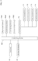
- FIG. 16A through FIG. 16C are diagrams depicting cutting modes when cutting the cutting material along a cutting line that has a corner portion.
- both the part A of a prescribed distance from the point of intersection of the corner portion on one cutting line and the part B of a prescribed distance from the point of intersection of the corner portion on the other cutting line are cut, i.e., die-cut.
- part A, of a prescribed distance of one of the cutting lines from the point of intersection at the corner portion, and part B, of a prescribed distance from the point of intersection at the corner portion of the other of the cutting line are left remaining, without being cut. That is, part A, of a prescribed distance of one of the cutting lines from the point of intersection at the corner portion, and part B, of a prescribed distance from the point of intersection at the corner portion of the other of the cutting line, are each connected parts that are not cut.
- part A of a prescribed distance of one of the cutting lines from the point of intersection at the corner portion
- part B of a prescribed distance from the point of intersection at the corner portion of the other of the cutting line
- FIG. 17A is a diagram depicting the state wherein a corner portion the cutting material, cut in the mode of cutting depicted in FIG. 16A , is bent upward.
- both sides of the corner portion of the cutting material are cut.
- the inside part of the corner portion of the cutting material may end up bent upwards.
- the point of intersection at the corner portion is connected, rather than being cut, for a prescribed distance on one of the cutting lines, and thus the inside part of the corner portion of the cutting material does not bend upward.
- FIG. 17B is a diagram depicting the state wherein a tip of the corner portion of the cutting material, cut in the mode of cutting depicted in FIG. 16B , is torn.
- both sides of the corner portion of the cutting material are connected, without having been cut.
- the tip end part C of the inside part of the corner portion of the cutting material can end up torn, as depicted in FIG. 17B .
- cutting is not to the point of intersection of the corner portion for either the one cutting line or the other than form the inside part of the corner portion of the cutting material.
- the inside part of the corner portion of the cutting material is constrained in two different directions from the outside part (that is, the direction that is perpendicular to the cutting line part A and the direction that is perpendicular to the cutting line part B).
- Producing a cut part that has a corner portion (the inside part of the corner portion of the cutting material) that is lined up cleanly requires pulling apart carefully.
- FIG. 17C is a diagram depicting the state wherein the corner portion of the cutting material, cut in the mode of cutting depicted in FIG. 16C , has been pulled apart cleanly.
- one part, part A, of the corner portion of the cutting material has been cut, but the other part, part B, is connected, without having been cut. Because the other part, part B, of the corner portion is connected, there is little tendency for the inside part of the corner portion of the material that is cut to bend upward.
- the one part, part A, of the corner portion of the material that is cut is cut up to the point of intersection at the corner portion, and thus this part A can be pulled apart easily.
- step (b) a connected part is left, without the cutting material being cut, for a distance that is set in advance from the point of intersection with the corner on a cutting line that is either the first cutting line or the second cutting line that form the corner portion of the cutting material, and the cutting material is cut along the one cutting line, except for the connected part.
- step (c) the cutting material is cut along the other cutting line so as to not leave a connected part up to a distance that has been determined in advance from the point of intersection of the corner.
Landscapes
- Engineering & Computer Science (AREA)
- Life Sciences & Earth Sciences (AREA)
- Forests & Forestry (AREA)
- Mechanical Engineering (AREA)
- General Engineering & Computer Science (AREA)
- Control Of Cutting Processes (AREA)
- Details Of Cutting Devices (AREA)
Abstract
Description
-
- (a) setting a cutting line with respect to the material to be cut, which is placed on the supporting platform;
- (b) cutting the material on a cutting line of a first cutting line or a second cutting line that form a corner portion where the direction of the cutting line turns, while leaving a connected part in which the material is not cut, at a distance that is determined in advance from the point of intersection at the corner portion, so as to cut along the cutting line except for the connected part; and
- (c) cutting the material on the other cutting line so as to not leave a connected part, at a distance that is predetermined from the point of intersection at corner portion.
-
- (a) Cutting lines S1 through S5 are set (referencing
FIG. 6 ) for a cuttingmaterial 200 that is placed on a supporting platform 10 (referencingFIG. 1 ); - (b) For one cutting line Sc12, of a first cutting line Sc11 and a second cutting line Sc12 that create a corner portion Sc1 wherein there is a change of direction in a cutting line S1 through S5, a part Sc14 is left connected, without the cutting
material 200 being cut, for a distance that is set in advance from the point of intersection of the corner portion Sc1, and the cuttingmaterial 200 is cut along the one cutting line Sc12, except for the connected part Sc14; - (c) On the other cutting line Sc11, the cutting
material 200 is cut so as to not leave a part that is connected, up to a distance that has been set in advance from the point of intersection of the corner portion Sc1.
- (a) Cutting lines S1 through S5 are set (referencing
-
- (b) For one cutting line Sc11, of a first cutting line Sc11 and a second cutting line Sc12, a part Sc13 is left connected, without the cutting
material 200 being cut, for a distance that is set in advance from the point of intersection of the corner portion Sc1, and the cuttingmaterial 200 is cut along the one cutting line Sc11, except for the connected part Sc13; - (c) On the other cutting line Sc12, the cutting
material 200 is cut so as to not leave a part that is connected, up to a distance that has been set in advance from the point of intersection of the corner portion Sc1.
- (b) For one cutting line Sc11, of a first cutting line Sc11 and a second cutting line Sc12, a part Sc13 is left connected, without the cutting
Claims (11)
Applications Claiming Priority (3)
| Application Number | Priority Date | Filing Date | Title |
|---|---|---|---|
| JP2018225391A JP6625721B1 (en) | 2018-11-30 | 2018-11-30 | Cutting machine |
| JP2018-225391 | 2018-11-30 | ||
| PCT/JP2019/046435 WO2020111147A1 (en) | 2018-11-30 | 2019-11-27 | Cutting machine |
Related Parent Applications (1)
| Application Number | Title | Priority Date | Filing Date |
|---|---|---|---|
| PCT/JP2019/046435 Continuation WO2020111147A1 (en) | 2018-11-30 | 2019-11-27 | Cutting machine |
Publications (2)
| Publication Number | Publication Date |
|---|---|
| US20200276726A1 US20200276726A1 (en) | 2020-09-03 |
| US11007666B2 true US11007666B2 (en) | 2021-05-18 |
Family
ID=69101008
Family Applications (1)
| Application Number | Title | Priority Date | Filing Date |
|---|---|---|---|
| US16/874,487 Active US11007666B2 (en) | 2018-11-30 | 2020-05-14 | Cutting machine |
Country Status (3)
| Country | Link |
|---|---|
| US (1) | US11007666B2 (en) |
| JP (1) | JP6625721B1 (en) |
| WO (1) | WO2020111147A1 (en) |
Citations (11)
| Publication number | Priority date | Publication date | Assignee | Title |
|---|---|---|---|---|
| JPH02243292A (en) | 1989-03-17 | 1990-09-27 | Mimaki Eng:Kk | Cutting notch forming method by cutting plotter |
| JPH02262995A (en) | 1988-12-21 | 1990-10-25 | Graphtec Corp | Control method for edge tip of image cutting device |
| JPH0624668A (en) | 1992-07-10 | 1994-02-01 | Hitachi Ltd | Device for stopping swing of tail cord for controlling elevator |
| JPH0624688A (en) | 1992-06-30 | 1994-02-01 | Tadano Ltd | Turning control device for cranes |
| JPH06155383A (en) | 1992-11-18 | 1994-06-03 | Mutoh Ind Ltd | Cutting pattern forming method in cutting plotter |
| JPH06246685A (en) | 1993-02-26 | 1994-09-06 | Mutoh Ind Ltd | Cutting plotter |
| JPH0739229A (en) | 1993-07-28 | 1995-02-10 | Kubota Corp | Winding string feeding structure of binding device |
| JPH07237183A (en) | 1994-02-23 | 1995-09-12 | Mutoh Ind Ltd | Sheet cutting method for cutting plotter |
| US20130008292A1 (en) * | 2011-07-05 | 2013-01-10 | Brother Kogyo Kabushiki Kaisha | Cutting apparatus and computer readable storage media |
| US20130104713A1 (en) | 2011-10-26 | 2013-05-02 | Brother Kogyo Kabushiki Kaisha | Cutting apparatus |
| US9927802B2 (en) * | 2013-10-25 | 2018-03-27 | Brother Kogyo Kabushiki Kaisha | Cutting data generator, cutting apparatus and non-transitory computer-readable medium |
Family Cites Families (1)
| Publication number | Priority date | Publication date | Assignee | Title |
|---|---|---|---|---|
| JPH0742683U (en) * | 1993-12-29 | 1995-08-11 | グラフテック株式会社 | Cutting plotter |
-
2018
- 2018-11-30 JP JP2018225391A patent/JP6625721B1/en active Active
-
2019
- 2019-11-27 WO PCT/JP2019/046435 patent/WO2020111147A1/en not_active Ceased
-
2020
- 2020-05-14 US US16/874,487 patent/US11007666B2/en active Active
Patent Citations (12)
| Publication number | Priority date | Publication date | Assignee | Title |
|---|---|---|---|---|
| JPH02262995A (en) | 1988-12-21 | 1990-10-25 | Graphtec Corp | Control method for edge tip of image cutting device |
| JPH02243292A (en) | 1989-03-17 | 1990-09-27 | Mimaki Eng:Kk | Cutting notch forming method by cutting plotter |
| JPH0624688A (en) | 1992-06-30 | 1994-02-01 | Tadano Ltd | Turning control device for cranes |
| JPH0624668A (en) | 1992-07-10 | 1994-02-01 | Hitachi Ltd | Device for stopping swing of tail cord for controlling elevator |
| JPH06155383A (en) | 1992-11-18 | 1994-06-03 | Mutoh Ind Ltd | Cutting pattern forming method in cutting plotter |
| JPH06246685A (en) | 1993-02-26 | 1994-09-06 | Mutoh Ind Ltd | Cutting plotter |
| JPH0739229A (en) | 1993-07-28 | 1995-02-10 | Kubota Corp | Winding string feeding structure of binding device |
| JPH07237183A (en) | 1994-02-23 | 1995-09-12 | Mutoh Ind Ltd | Sheet cutting method for cutting plotter |
| US20130008292A1 (en) * | 2011-07-05 | 2013-01-10 | Brother Kogyo Kabushiki Kaisha | Cutting apparatus and computer readable storage media |
| US20130104713A1 (en) | 2011-10-26 | 2013-05-02 | Brother Kogyo Kabushiki Kaisha | Cutting apparatus |
| JP2013091133A (en) | 2011-10-26 | 2013-05-16 | Brother Industries Ltd | Cutting apparatus |
| US9927802B2 (en) * | 2013-10-25 | 2018-03-27 | Brother Kogyo Kabushiki Kaisha | Cutting data generator, cutting apparatus and non-transitory computer-readable medium |
Also Published As
| Publication number | Publication date |
|---|---|
| JP6625721B1 (en) | 2019-12-25 |
| US20200276726A1 (en) | 2020-09-03 |
| WO2020111147A1 (en) | 2020-06-04 |
| JP2020082325A (en) | 2020-06-04 |
Similar Documents
| Publication | Publication Date | Title |
|---|---|---|
| JP4888582B2 (en) | Robot device, processing system, and method of manufacturing processed product | |
| JP6263543B2 (en) | Apparatus and method for scraping multilayer sheets comprising a support liner and at least one adhesive film bonded to the liner | |
| JP5725868B2 (en) | End processing equipment | |
| US11021823B2 (en) | Perforating apparatus and embroidery sewing machine with the perforating apparatus | |
| JP6654332B2 (en) | Feeding method of strip work of press machine | |
| US11007666B2 (en) | Cutting machine | |
| US8562778B2 (en) | Tape adhering apparatus and tape adhering method | |
| JP2020092244A (en) | Tape sticking device | |
| JP5197889B1 (en) | Wire electric discharge machine and wire electrode removal apparatus | |
| KR100822501B1 (en) | Cutting machine | |
| JP5128012B1 (en) | Wire electric discharge machine and wire electrode removal apparatus | |
| JPH10128697A (en) | Drilling device for soft sheet such as ceramic green sheet, flexible board | |
| JP5494617B2 (en) | Robot system and method of manufacturing processed product | |
| JP5149073B2 (en) | CUTTING METHOD, CUTTING DEVICE, CONTROL PROGRAM THEREOF, AND STORAGE MEDIUM STORING THE SAME | |
| KR20090122197A (en) | Apparatus, device and method for rubber-coating of cutting dies | |
| JP2005118971A (en) | Wire electric discharge machine and method for determining machining reference position of wire electric discharge machine | |
| JP6715261B2 (en) | Board working machine and insertion method | |
| JP2007015043A (en) | Work fixing device | |
| JP2003220594A (en) | Cutting plotter | |
| JP2016113278A (en) | Sticking device of double-sided tape, sticking method of double-sided tape, and sticking program of double-sided tape | |
| JP2608969B2 (en) | Work control method in through hole forming | |
| TWI738572B (en) | Robot system and its operating method | |
| JP2009531190A (en) | Platform for supporting a workpiece to be cut from a sheet-like material and method for supporting the same | |
| KR102049549B1 (en) | Method for processing fabric | |
| JP4846678B2 (en) | Electronic component mounting device |
Legal Events
| Date | Code | Title | Description |
|---|---|---|---|
| AS | Assignment |
Owner name: ROLAND DG CORPORATION, JAPAN Free format text: ASSIGNMENT OF ASSIGNORS INTEREST;ASSIGNORS:YAMAMOTO, SHINYA;IGARASHI, MASAKAZU;TOZUKA, TAKESHI;AND OTHERS;REEL/FRAME:052668/0122 Effective date: 20200409 |
|
| FEPP | Fee payment procedure |
Free format text: ENTITY STATUS SET TO UNDISCOUNTED (ORIGINAL EVENT CODE: BIG.); ENTITY STATUS OF PATENT OWNER: LARGE ENTITY |
|
| STPP | Information on status: patent application and granting procedure in general |
Free format text: NOTICE OF ALLOWANCE MAILED -- APPLICATION RECEIVED IN OFFICE OF PUBLICATIONS |
|
| STPP | Information on status: patent application and granting procedure in general |
Free format text: PUBLICATIONS -- ISSUE FEE PAYMENT RECEIVED |
|
| STPP | Information on status: patent application and granting procedure in general |
Free format text: PUBLICATIONS -- ISSUE FEE PAYMENT VERIFIED |
|
| STCF | Information on status: patent grant |
Free format text: PATENTED CASE |
|
| MAFP | Maintenance fee payment |
Free format text: PAYMENT OF MAINTENANCE FEE, 4TH YEAR, LARGE ENTITY (ORIGINAL EVENT CODE: M1551); ENTITY STATUS OF PATENT OWNER: LARGE ENTITY Year of fee payment: 4 |
|
| AS | Assignment |
Owner name: ROLAND DG CORPORATION, JAPAN Free format text: MERGER AND CHANGE OF NAME;ASSIGNORS:ROLAND DG CORPORATION;XYZ CORPORATION;REEL/FRAME:070314/0329 Effective date: 20241204 |