US11007641B2 - Continuum robot control methods and apparatus - Google Patents
Continuum robot control methods and apparatus Download PDFInfo
- Publication number
- US11007641B2 US11007641B2 US16/029,461 US201816029461A US11007641B2 US 11007641 B2 US11007641 B2 US 11007641B2 US 201816029461 A US201816029461 A US 201816029461A US 11007641 B2 US11007641 B2 US 11007641B2
- Authority
- US
- United States
- Prior art keywords
- bending section
- angle
- bending
- distal
- proximal
- Prior art date
- Legal status (The legal status is an assumption and is not a legal conclusion. Google has not performed a legal analysis and makes no representation as to the accuracy of the status listed.)
- Active - Reinstated, expires
Links
Images


Classifications
-
- B—PERFORMING OPERATIONS; TRANSPORTING
- B25—HAND TOOLS; PORTABLE POWER-DRIVEN TOOLS; MANIPULATORS
- B25J—MANIPULATORS; CHAMBERS PROVIDED WITH MANIPULATION DEVICES
- B25J9/00—Program-controlled manipulators
- B25J9/16—Program controls
- B25J9/1615—Program controls characterised by special kind of manipulator, e.g. planar, scara, gantry, cantilever, space, closed chain, passive/active joints and tendon driven manipulators
- B25J9/1625—Truss-manipulator for snake-like motion
-
- B—PERFORMING OPERATIONS; TRANSPORTING
- B25—HAND TOOLS; PORTABLE POWER-DRIVEN TOOLS; MANIPULATORS
- B25J—MANIPULATORS; CHAMBERS PROVIDED WITH MANIPULATION DEVICES
- B25J9/00—Program-controlled manipulators
- B25J9/06—Program-controlled manipulators characterised by multi-articulated arms
- B25J9/065—Snake robots
-
- B—PERFORMING OPERATIONS; TRANSPORTING
- B25—HAND TOOLS; PORTABLE POWER-DRIVEN TOOLS; MANIPULATORS
- B25J—MANIPULATORS; CHAMBERS PROVIDED WITH MANIPULATION DEVICES
- B25J9/00—Program-controlled manipulators
- B25J9/0009—Constructional details, e.g. manipulator supports, bases
- B25J9/0015—Flexure members, i.e. parts of manipulators having a narrowed section allowing articulation by flexion
-
- B—PERFORMING OPERATIONS; TRANSPORTING
- B25—HAND TOOLS; PORTABLE POWER-DRIVEN TOOLS; MANIPULATORS
- B25J—MANIPULATORS; CHAMBERS PROVIDED WITH MANIPULATION DEVICES
- B25J9/00—Program-controlled manipulators
- B25J9/10—Program-controlled manipulators characterised by positioning means for manipulator elements
- B25J9/104—Program-controlled manipulators characterised by positioning means for manipulator elements with cables, chains or ribbons
Definitions
- the present disclosure relates to a control system of a continuum robot. More particularly, the present disclosure is directed toward methods, systems and apparatus for a continuum robot configured with independently manipulatable bendable section for advancing the robot through a passage, without contacting fragile elements within the passage.
- a continuum robot includes a plurality of bending sections having a flexible structure, wherein the shape of the continuum robot is controlled by deforming the bending sections.
- the robot mainly has two advantages over a robot including rigid links. The first advantage is that the continuum robot can move along a curve in a narrow space or in an environment with scattered objects in which the rigid link robot may get stuck. The second advantage is that it is possible to operate the continuum robot without damaging surrounding fragile elements because the continuum robot has intrinsic flexibility.
- every pair of adjacent bending sections are controlled so that the bending shape of a leading section becomes the bending shape of the following section as an endoscope base advances, and thereby the shape is continuously propagated, which may lead to unwanted contact with fragile elements as the endoscope is advanced.
- the continuum robot when used as an endoscope by setting an image-capturing device at the most distal end of the continuum robot, a motion of temporarily stopping the base and looking around (which is referred to as a “look-around motion”) is performed.
- the control method of continuously propagating the bending posture of the most distal end to the following bending section by the length of the bending section is applied to the look-around motion, the look-around motion of the most distal end is propagated to the following bending posture, and the continuum robot becomes more likely to contact elements in a small and narrow space.
- the method has problems in that the continuum robot cannot advance into a small and narrow space as friction increases due to increase of a normal force with an obstacle and the continuum robot becomes more likely to break.
- the presently disclosed apparatus teaches a robotic apparatus comprising: a continuum robot including a plurality of bending sections including a distal bending section and a proximal bending section wherein each of the bending sections are bent by at least one wire; a driver that drives the wire; a controller that controls a driving amount of the wire; and a base affixed to the continuum robot and capable of moving the continuum robot, wherein, when a base moves the continuum robot a displacement value, the distal bending section performs a rotational motion, and an angle ( ⁇ t) of the rotational motion is 360 degrees or more, and the controller controls the proximal bending section so as to follow the distal bending section while preventing the proximal bending section from performing a rotational motion of 360 degrees or more, based on a bending state of the distal bending section at a time when the distal bending section finishes the rotational motion.
- the robot apparatus controller may calculates an angle ( ⁇ t′) that is 0 degrees or more and 360 degrees or less and the angle ( ⁇ t′) has a same phase as the angle ( ⁇ t) of the rotational motion, and performs bending control of the proximal bending section based on the calculated angle ( ⁇ t′).
- the robotic apparatus further provides, wherein, regarding the proximal bending section, the controller calculates an angle ( ⁇ t′′) that is ⁇ 180 degrees or more and less than 180 degrees and that has a same phase as the angle ( ⁇ t) of the rotational motion, and performs bending control of the proximal bending section based on ⁇ t′′.
- the robotic apparatus discloses wherein, regarding the proximal bending section, when the distal bending section performs a rotational motion while the predetermined base displacement changes by a predetermined value and the angle ( ⁇ t) of the rotational motion is 360 degrees or more, regarding the proximal bending section, an angle ( ⁇ t′′) that is ⁇ 180 degrees or more and less than 180 degrees and that has a same phase as the angle of the rotational motion is calculated, and bending control of the proximal bending section is performed based on ⁇ t′′.
- the robotic apparatus provided: wherein, regarding the proximal bending section, the controller performs bending control based on bending control of the distal bending section during a period in which the base displacement changes by a predetermined value ( ⁇ z′).
- the robotic apparatus provided: wherein, when the base has the displacement value, the controller determines whether or not the distal bending section performs a rotational motion whose angle ( ⁇ t) is 360 degrees or more.
- the robotic apparatus teaches, wherein the distal bending section includes two independent bending sections.
- Another embodiment of the subject robot includes further comprising a medial bending section wherein the medial bending section is bent by at least one wire.
- FIG. 1 illustrates a kinematic model of the subject continuum robot, according to one or more embodiment of the subject apparatus, method or system.
- FIG. 2 provides a detailed illustration of the subject continuum robot, according to one or more embodiment of the subject apparatus, method or system.
- FIG. 3 is a top perspective view of the subject continuum robot, according to one or more embodiment of the subject apparatus, method or system.
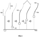
- FIG. 4 illustrates an exemplary procedure of a leader following control utilized in the subject continuum robot, according to one or more embodiment of the subject apparatus, method or system.
- FIGS. 5( a ) and 5( b ) provide control systems for the subject continuum robot, according to one or more embodiment of the subject apparatus, method or system.
- FIG. 6 illustrates the control system for the subject continuum robot, according to one or more embodiment of the subject apparatus, method or system.
- FIG. 7 is a block diagram illustrating the control system of the subject continuum robot, according to one or more embodiment of the subject apparatus, method or system.
- FIGS. 8( a ) through 8( d ) illustrate a simulation for controlling the subject continuum robot, according to one or more embodiment of the subject apparatus, method or system.
- FIGS. 9( a ) through 9( d ) provide a simulation for controlling the subject continuum robot, according to one or more embodiment of the subject apparatus, method or system.
- FIG. 10 illustrates a control system for controlling the subject continuum robot, according to one or more embodiment of the subject apparatus, method or system.
- FIGS. 11( a ) through 11( d ) illustrate a simulation for controlling the subject continuum robot, according to one or more embodiment of the subject apparatus, method or system.
- FIGS. 12( a ) through 12( d ) illustrate a simulation for controlling the subject continuum robot, according to one or more embodiment of the subject apparatus, method or system.
- FIGS. 13( a ) and 13( b ) illustrate control systems for controlling the subject continuum robot, according to one or more embodiment of the subject apparatus, method or system.
- FIGS. 14( a ) through 14( d ) illustrate a simulation result for controlling the subject continuum robot, according to one or more embodiment of the subject apparatus, method or system.
- FIGS. 15( a ) through 15( d ) illustrate a simulation result for controlling the subject continuum robot, according to one or more embodiment of the subject apparatus, method or system.
- Applicant will first detail the mechanism of a continuum robot, followed by the control algorithms that enable the continuum robot to operate and advance into a path, as well as the systems and procedures associated with the continuum robot and said functionality.
- FIGS. 5( a ) and 5( b ) are graphs representing a table of a bending angle command with respect to a base displacement for the robot.
- the bending angle command for a follower may be automatically generated so that the bending angle becomes cD and the rotational angle becomes cd at a base displacement c.
- This will be referred to as a first leader following control method.
- 2 ⁇ rad is subtracted from the rotational angle command as illustrated in FIG. 6 .
- this will be referred to as a second leader following control method.
- FIG. 7 shows a block diagram of the subject continuum robot, according to one or more embodiment of the subject apparatus, method or system.
- P denotes a control target
- FTL denotes a first leader following control algorithm
- ⁇ tref and ⁇ tref denote a bending angle command value and a rotational angle command value for the most distal end
- ⁇ fref and ⁇ fref denote a bending angle command vector and a rotational angle command vector
- z b denotes a base displacement command value
- the block f denotes a second leader following control algorithm.
- the block K represents kinematic calculation and calculates a wire driving amount from the bending and rotational angle command values. Details and control results obtained by simulations will be described below.
- FIG. 1 illustrates a continuum robot 100 that is capable of a plurality of bends, with FIG. 2 providing an enlarged view of a first bending section 102 at the proximal end 104 of the robot 100 .
- wires 111 , 112 and 113 are connected to connection portions 121 , 122 and 123 , respectively, found on an end disc 160 found at the distal end 106 of each bending section 102 , Wherein the posture of the bending section 102 is controlled by pushing and pulling the wires 111 to 113 by using actuators 130 to 132 disposed in a robot base 140 .
- the robot base 140 of the continuum robot 100 is disposed on a base stage (not shown) and can be moved by the base stage in the longitudinal direction. Thus, it is possible to advance and retard the robot 100 into a target structure by advancing and retarding the base stage.
- a controller indicates a driving amount to the base stage and the actuators 130 to 132 .
- the controller may also be described or eluded to as a control system.
- the controller may include dedicated hardware including a field-programmable gate array (“FPGA”) and the like; or may be a computer including a storage unit, a work memory, and a central processing unit (“CPU”).
- the storage unit may store a software program corresponding to an algorithm of the control system (described below) and the central processing unit expands the program in the work memory, executes the program line by line, and thereby the computer functions as the controller.
- the controller is communicably connected to the base stage and the actuators 130 to 132 , and the controller send signals representing the driving amount and configuration to these control targets.
- the continuum robot 100 includes wire guides 161 to 164 situated throughout each bending section 102 , for guiding the wires 111 , 112 and 113 , and for providing structural integrity to the bending section 102 .
- the wire guides 161 to 164 each contain a wire through 150 - 153 for each wire 111 - 113 .
- FIG. 2 only depicts the wire through 150 - 153 for a single wire 111 .
- a method of discretely arranging the plurality of wire guides, a continuum robot 100 having a bellows-like shape or a mesh-like shape may be utilized, wherein the wire guides 161 - 164 are fixed to their respective wires 111 - 113 .
- l d the length of the central axis a bending section
- ⁇ n the bending angle of the distal end
- ⁇ n the rotational angle of the distal end
- ⁇ n the radius of curvature of a bending section.
- the wires 111 - 113 may be referred to as wires a, b, and c, counterclockwise in the in the xy plane; and the driving displacements of the wires for driving the n-th bending section are denoted by l pna , l pnb , and l pnc .
- the wires a-c are disposed at the vertices of an equilateral triangle whose side has a length r s .
- the kinematics of the continuum robot 100 may be derived: 1. In each bending section, the wires deform with a constant curvature; 2. Twisting deformation of the wires is not considered; 3. The wires do not deform in the longitudinal direction; 4. Friction between the wire guides and the wires is not considered.
- the relationships between the driving displacements l pna , l pnb , and l pnc of the wires a, b, and c and the bending angle ⁇ n and the rotational angle ⁇ n of the distal end are obtained.
- the phase angle of the wires for driving the n-th bending section is expressed as follows, where e denotes the number of bending sections.
- the driving displacements l pna , l pnb , and l pnc of the wires of the n-th bending section are expressed as follows.
- leader following control is a method of performing control so that a following bending section passes through the same path as a path through which a bending section at the most distal end passes.
- the continuum robot 100 can advance through a space, while retaining the original bend initiated to avoid contact, as well as initiating new bends to avoid up and coming obstacles.
- the path need not be determined beforehand. It is sufficient that the bending angle of the most distal end is continuously propagated to the following bending section by a bending section length.
- an operator can perform the leader following control in real time by only giving commands with respect to the bending angle of the most distal end of the robot 100 while advancement of the base is promoted by using a joystick or the like.
- the horizontal line represents the passage of time as the robot 100 is advanced into the desired space, with the arrows signifying a progression of time.
- the first bending section 102 takes the shape of the first desired bend (dotted line) 190 .
- Further progression of the base 140 depicts the second bending section 104 taking the shape of the first desired bend 190 , while the first bending section 102 takes the shape of the second desired bend 192 . Additional bending sections and desired bends are contemplated and further claimed herein.
- FIGS. 5( a ) and 5( b ) are graphs in which the horizontal axes represent the base displacement z b and the vertical axes respectively represent the bending angle ⁇ and the rotational angle ⁇ .
- the thinner broken line represents a bending command given by an operator to the distal bending section
- the thicker broken line represents a bending command to the following bending section (follower).
- the bending angle for the follower may be automatically generated so that the bending angle and the rotational angle respectively become cD and cd at the base displacement c.
- the base displacement c is determined so that the distance ac becomes the bending section length l d . Then, the bending angle command of the follower is stored in the storage unit of the control processing device and read out in accordance with the base displacement.
- the number of bending sections is two or more, it is possible to obtain bending angle command values for all bending sections by substituting the follower section in the above description with the distal end and by continuously performing the processing.
- the bending angle command of the follower is interpolated so as to connect the point a and the point D and the rotational angle command is interpolated so as to connect the point a and the point d.
- the solid line in FIG. 5 represents the interpolated bending angle command for the follower.
- the angle command generation algorithm described in this section is referred to as a first leader follower control method.
- the follower When the first leader follower control method described in the previous section is applied to a command value in which the rotational angle command ab exceeds 2 ⁇ rad, the follower performs a rotational motion of one or more rotations around the z axis as the base advances. It is considered that a rotation operation command given by an operator to perform a rotational motion of one or more rotations around the z axis at the base displacement a is, for example, a motion of looking around at the position by using an image-capturing device disposed at the distal end of the robot. When the base advances after the look-around motion, the follower need not perform this motion. This is because it is difficult to dispose an image-capturing device or the like in the follower section, because the follower section is continuous with the leading section.
- a second leader following control algorithm illustrated in FIG. 6 is created.
- the solid line, the thick broken line, and the broken line respectively represent a bending angle command after interpolation, a bending angle command before interpolation, and a command by an operator.
- n denotes a natural number.
- the second leader follower control algorithm calculates a rotational angle command cd′ as a rotation command for the second follower by subtracting a rotational motion of n rotations from the rotation command for the leader; and then interpolates a rotational angle command so as to connect the point a and the point d′ in the same way as in the first follower control method.
- the rotational angle command cd′ for the follower can be calculated from the following formulas.
- ⁇ cd′ ⁇ cd mod 2 ⁇ ( ⁇ cd >2 ⁇ )
- ⁇ cd′ ⁇ cd mod ⁇ 2 ⁇ ( ⁇ cd ⁇ 2 ⁇ ) (4)
- ⁇ cd and ⁇ cd′ respectively denote the rotational angle commands cd and cd′.
- the symbol “mod” represents modular arithmetic, and the sign of the solution is the same as the divisor.
- FIG. 7 illustrates a block diagram illustrating the control system 170 of the subject continuum robot 100 , according to one or more embodiment of the subject apparatus, method or system.
- the control system 100 comprises a control target 172 , a first leader following control algorithm 174 , wherein ⁇ tref and ⁇ tref denote a bending angle command value and a rotational angle command value of the distal end, and ⁇ fref and ⁇ fref represent a bending angle command vector and a rotational angle command vector.
- z b denotes a base displacement command value, with the control system 170 further utilizing the modular arithmetic 178 shown in Formula (4).
- the kinematic calculation 178 described in the first chapter, calculates a wire driving amount from the bending and rotational angle command values.
- All simulations are performed by using one or more embodiment of the leader follower control system described in the previously.
- the simulation is performed on a continuum robot that includes two bending sections each having a bending section length of 0.01 m.
- FIGS. 8( a ) to 8( d ) are simulations by stick diagrams illustration, wherein a stepwise manner, the postures when control using the second leader following control algorithm is performed until the base advances to 0.01 m.
- the solid line represents the shape of the robot
- the black dot represents the distal end of each bending section
- the thin solid line represents the locus of the distal end of each bending section.
- the second bending section has already performed a look-around motion of two rotations around the z axis.
- the bending angle ⁇ 1 of the final posture is equal to the bending angle ⁇ 2 of the initial posture
- the rotational angle ⁇ 1 of the final posture is an angle calculated from the bending angle ⁇ 2 of the initial posture by performing modular arithmetic as follows.
- FIGS. 9( a ) to 9( d ) illustrate responses due to the first leader follower control algorithm.
- the look-around motion of the second bending section is directly propagated to the motion of the first bending section, and therefore the first bending section performs a rotational motion of two rotations as the base advances.
- the first bending section performs a rotational motion of two rotations as the base advances.
- the solid line, the thick broken line, and the broken line respectively represent a bending angle command after interpolation, a bending angle command before interpolation, and a command by an operator.
- the third leader follower control algorithm performs the second leader follower control algorithm; and then calculates a rotational angle command cd′′ as a rotation command for the follower by adding or subtracting 2 ⁇ to or from the rotation command for the leader. Then, in the same way as in the second leader follower control method, the algorithm interpolates the rotational angle command so as to connect the point a and the point d′′.
- the rotational angle command cd′′ for the follower can be calculated from the following formulas.
- ⁇ cd′′ ⁇ + ⁇ cd′ mod ⁇ ( ⁇ cd′ > ⁇ )
- ⁇ cd′′ ⁇ + ⁇ cd′ mod ⁇ ( ⁇ cd′ ⁇ ) (5)
- FIGS. 11( a ) to 11( d ) are stick diagrams illustrating, in a stepwise manner, the postures when control using the third leader follower control algorithm is performed and the base advances by 0.01 m.
- the solid line represents the shape of the robot
- the black dot represents the distal end of each bending section
- the thin solid line represents the locus of the distal end of each bending section.
- the initial posture shown in FIG. 11( a ) is expressed as follows.
- the bending angle ⁇ 1 of the final posture is equal to the bending angle ⁇ 2 of the initial posture
- the rotational angle ⁇ 1 of the final posture is an angle calculated from the bending angle ⁇ 2 of the initial posture by performing modular arithmetic as follows.
- FIGS. 12( a ) to 12( d ) illustrate responses due to the second leader follower control algorithm.
- the first bending section rotates in the same direction as the motion of the second bending section, and therefore the rotation amount due to the advancement of the base is large.
- the second bending section rotate by a large amount as the base advances, and contact with external environment is likely to occur in a narrow and small space.
- the rotation amount of the follower section is reduced by operating the rotational angle command.
- the solid line, the thick broken line, and the broken line respectively represent a bending angle command after interpolation, a bending angle command before interpolation, and a command by an operator.
- the fourth leader follower control algorithm performs the third leader following control algorithm; and then calculates a rotational angle command cd′′′ as a rotation command for the follower by adding or subtracting ⁇ to or from a rotation command for the leader. Then, in the same way as in the third leader follower control method, the algorithm interpolates the rotational angle command so as to connect the point a and the point d′′′.
- the rotational angle command cd′′′ for the follower can be calculated from the following formulas.
- ⁇ cD′ and ⁇ cD respectively denote the bending angle commands cD and cD′.
- FIGS. 14( a ) to 14( d ) are stick diagrams illustrating, in a stepwise manner, the postures when control using the third leader follower control algorithm is performed and the base advances by 0.01 m.
- the solid line represents the shape of the robot, the black dot represents the end of each bending section, and the thin solid line represents the locus of the end of each bending section.
- the initial posture shown in FIG. 14( a ) is expressed as follows.
- the bending angle ⁇ 1 of the final posture has a sign opposite to the sign of the bending angle ⁇ 2 of the initial posture, and the rotational angle ⁇ 1 of the final posture is an angle calculated from the bending angle ⁇ 2 of the initial posture by performing addition and subtraction as follows.
- FIGS. 12( a ) to 12( d ) illustrate responses due to the third leader follower control algorithm.
- the rotation amount due to the advancement of the base is large.
- the distal end of the second bending section shows a locus on an arc, and contact with external environment is likely to occur in a narrow and small space.
- a controller when a distal bending section performs a rotational motion wherein the angle ( ⁇ cd or ⁇ t) of the rotational motion is 360 degrees or more, a controller performs bending control so that a proximal bending section follows the distal bending section while preventing the proximal bending section from performing a rotational motion of 360 degrees or more. That is, based on the direction of the distal bending section at the start and at the end of the rotational motion, the effect of unnecessary rotation is avoided, and therefore it is possible to reduce or eliminate issues, such as contact with external environment.
- the following advantages are obtained. For example, consider a case wherein advancement of the continuum robot is stopped, the distal portion is rotated, image capturing is performed while looking around by using an objective lens disposed at the distal end of the continuum robot, and subsequently the robot is further advanced. In this case, it is considered that the look-around motion does not affect the advancement of the robot.
- By performing control according to the embodiments it is possible to advance the proximal bending section so as to follow the distal bending section without being affected by the look-around motion.
- the controller calculates an angle ( ⁇ cd′ or ⁇ t′) that is 0 degrees or more and less than 360 degrees and that has the same phase as the angle of the rotational motion, and performs bending control of the proximal bending section based on the calculated angle.
- the aforementioned (4) may be used as the calculation formulas, or other theoretical formulas that provide the same result may be used. When realizing these formulas by using a computer, necessary approximation may be used.
- an angle ( ⁇ cd′′ or ⁇ t′′) that is ⁇ 180 degrees or more and less than 180 degrees and that has the same phase as the angle of the rotational motion is calculated, and bending control of the proximal bending section based on ⁇ cd′′ is performed.
- the rotational motion of the proximal bending section is limited to 180 degrees or less, and therefore unnecessary motion of the proximal portion is further suppressed.
- the aforementioned (4) and (5) may be used as the calculation formulas, or other theoretical formulas that provide the same result may be used. When realizing these formulas by using a computer, necessary approximation may be used.
- the controller calculates an angle ⁇ cd′′′ obtained from the following formulas obtained by using the aforementioned (4), (5) and (6) using the angle ⁇ cd (or ⁇ t) of the rotational motion of the distal bending section.
- the controller calculates an angle ⁇ cD′ obtained by using the aforementioned formula (6) using the bending angle ⁇ cD of the distal bending section.
- the proximal bending section is bent to be in a state in which the proximal bending section is bent by the bending angle ⁇ cD′ and rotated by the angle ⁇ cd′′′ of the rotational motion.
- the aforementioned (4), (5) and (6) may be used as the calculation formulas, or other theoretical formulas that give the same result may be used. When realizing these formulas by using a computer, necessary approximation may be used.
- the proximal bending section when the distal bending section performs a general bending motion including a rotational motion at a certain base displacement zb, as illustrated in FIGS. 5( a ) and 6 , the proximal bending section is controlled so that the proximal bending section gradually bends while the proximal bending section becomes displaced by the length ac.
- the distal bending section when the distal bending section performs a bending motion by a predetermined angle while the distal bending section becomes displaced by a very short ⁇ z ( ⁇ 0), the proximal bending section gradually bends by an angle corresponding to the predetermined angle while the proximal bending section becomes displaced for a distance larger than ⁇ z.
- the controller determines whether or not the distal bending section performs a rotational motion of an angle ( ⁇ t) that is 360 degrees or more for a predetermined change ⁇ z ( ⁇ 0) of the base displacement zb.
- Such control may be determined based on the fact that the distal bending section has actually performed a rotational motion or may be determined based on the fact that a driving amount or a control value for performing the rotational motion has been input to the actuators 130 to 132 . Alternatively, it may be determined when the driving amount or the control value is calculated by the controller.
- control according to the present disclosure not only in cases where the control described above is performed, but also in situations where the bending motion or the rotational motion of the proximal portion is performed, for example, depending on the history or the locus of the bending motion or the rotational motion of the distal portion.
- bending control of the distal end of the robot is determined based on the bending motion or the rotational motion of the distal portion.
- embodiments of the present disclosure are not limited to this embodiment.
- two bending sections in the distal portion may perform a rotational motion in synchronism or the second most distal bending section may perform a rotational motion.
- the control algorithms described above may be applied to bending control of a bending section on the proximal side of the two bending sections.
- Such an embodiment is also included in the embodiments of the present disclosure. The point is that, when there are two bending sections in the distal portion, based on the rotational motion of bending sections in the distal portion, the aforementioned control algorithm may be applied to a bending section on the proximal side.
- the controller may determine that the control algorithm according to an embodiment of the present disclosure is applied based on various set(s) of information. In the case where the control algorithm is not applied, for example, control shown in the graph illustrated in FIG. 5( b ) is performed.
Landscapes
- Engineering & Computer Science (AREA)
- Robotics (AREA)
- Mechanical Engineering (AREA)
- Health & Medical Sciences (AREA)
- General Health & Medical Sciences (AREA)
- Orthopedic Medicine & Surgery (AREA)
- Endoscopes (AREA)
- Manipulator (AREA)
- Instruments For Viewing The Inside Of Hollow Bodies (AREA)
Abstract
Description
ζt′=ζt mod 2π(ζt>2π)
ζt′=ζt mod −2π(ζt<−2π).
ζt′=ζt mod 2π(ζt>2π)
ζt′=ζt mod −2π(ζt<−2π)
ζt″=−π+ζt′ mod π(ζt′>π)
ζt″=π+ζt′ mod−π(ζt′<−π).
ζt′=ζt mod 2π(ζt>2π)
ζt′=ζt mod −2π(ζt<−2π)
ζt″=−π+ζt′ mod π(ζt′>π)
ζt″=π+ζt′ mod −π(ζt′<−π)
ζt′″=ζt″−π(π/2<ζt″<π)
ζt′″=ζt″+π(−π<ζt″<−π/2),
calculates an angle θ′ obtained by using the following formula using a bending angle θ of the distal bending section, θ′=−θ, and bends the proximal bending section to be in a state in which the proximal bending section is bent at the bending angle θ′ and rotated by the angle ζt′″ of the rotational motion.
ζf′=ζt mod 2π(ζt>2π)
ζf′=ζt mod −2π(ζt>2π).
ζf″=−π+ζt′ mod π(ζt′>π)
ζf″=π+ζt′ mod −π(ζt′>−π).
ζf′″=ζt″−π(π/2<ζt″<π)
ζf′″=ζt″+π(−π<ζt″<−π/2).
ζcd′=ζcd mod 2π(ζcd>2π)
ζcd′=ζcd mod−2π(ζcd<−2π) (4)
ζcd″=−π+ζcd′ mod π(ζcd′>π)
ζcd″=π+ζcd′ mod−π(ζcd′<−π) (5)
Claims (14)
ζt′=ζt mod 2π(ζt>2π)
ζt′=ζt mod −2π(ζt<−2π).
ζt′=ζt mod 2π(ζt>2π)
ζt′=ζt mod −2π(ζt<−2π)
ζt″=−π+ζt′ mod π(ζt′>π)
ζt″=π+ζt′ mod−π(ζt′<−π).
ζt′=ζt mod 2π(ζt>2π)
ζt′=ζt mod −2π(ζt<−2π)
ζt″=−π+ζt′ mod π(ζt′>π)
ζt″=π+ζt′ mod−π(ζt′<−π)
ζt′″=ζt″−π(π/2<ζt″<π)
ζt′″=ζt″+π(−π<ζt″<−π/2),
ζf′=ζt mod 2π(ζt>2π)
ζf′=ζt mod−2π(ζt>2π).
ζf″=−π+ζt′ mod π(ζt′>π)
ζf″=π+ζt′ mod −π(ζt′>−π).
ζf′″=ζt″−π(π/2<ζt″<π)
ζf′″=ζt″+π(−π<ζt″<−π/2).
Priority Applications (2)
| Application Number | Priority Date | Filing Date | Title |
|---|---|---|---|
| US16/029,461 US11007641B2 (en) | 2017-07-17 | 2018-07-06 | Continuum robot control methods and apparatus |
| US17/233,150 US11685046B2 (en) | 2017-07-17 | 2021-04-16 | Continuum robot control methods and apparatus |
Applications Claiming Priority (2)
| Application Number | Priority Date | Filing Date | Title |
|---|---|---|---|
| US201762533466P | 2017-07-17 | 2017-07-17 | |
| US16/029,461 US11007641B2 (en) | 2017-07-17 | 2018-07-06 | Continuum robot control methods and apparatus |
Related Child Applications (1)
| Application Number | Title | Priority Date | Filing Date |
|---|---|---|---|
| US17/233,150 Continuation US11685046B2 (en) | 2017-07-17 | 2021-04-16 | Continuum robot control methods and apparatus |
Publications (2)
| Publication Number | Publication Date |
|---|---|
| US20190015978A1 US20190015978A1 (en) | 2019-01-17 |
| US11007641B2 true US11007641B2 (en) | 2021-05-18 |
Family
ID=65000092
Family Applications (2)
| Application Number | Title | Priority Date | Filing Date |
|---|---|---|---|
| US16/029,461 Active - Reinstated 2039-11-19 US11007641B2 (en) | 2017-07-17 | 2018-07-06 | Continuum robot control methods and apparatus |
| US17/233,150 Active US11685046B2 (en) | 2017-07-17 | 2021-04-16 | Continuum robot control methods and apparatus |
Family Applications After (1)
| Application Number | Title | Priority Date | Filing Date |
|---|---|---|---|
| US17/233,150 Active US11685046B2 (en) | 2017-07-17 | 2021-04-16 | Continuum robot control methods and apparatus |
Country Status (2)
| Country | Link |
|---|---|
| US (2) | US11007641B2 (en) |
| JP (1) | JP6596126B2 (en) |
Cited By (3)
| Publication number | Priority date | Publication date | Assignee | Title |
|---|---|---|---|---|
| US12082883B2 (en) | 2020-01-09 | 2024-09-10 | Canon U.S.A., Inc. | Enhanced planning and visualization with curved instrument pathway and its curved instrument |
| US12426957B2 (en) | 2021-07-07 | 2025-09-30 | Canon U.S.A., Inc. | Bendable medical device with multiple position sensors |
| US12521520B2 (en) | 2021-12-29 | 2026-01-13 | Canon U.S.A., Inc. | Catheter packaging having alignment features |
Families Citing this family (33)
| Publication number | Priority date | Publication date | Assignee | Title |
|---|---|---|---|---|
| GB2557179B (en) * | 2016-11-29 | 2020-01-01 | Rolls Royce Plc | Methods, apparatus, computer programs and non-transitory computer readable storage mediums for controlling a hyper redundant manipulator |
| US11865702B2 (en) * | 2017-10-31 | 2024-01-09 | Worcester Polytechnic Institute | Robotic gripper member |
| US11097430B2 (en) * | 2017-10-31 | 2021-08-24 | Worcester Polytechnic Institute | Robotic gripper member |
| US11458641B2 (en) * | 2018-05-23 | 2022-10-04 | General Electric Company | Robotic arm assembly construction |
| CN110193827B (en) * | 2019-03-28 | 2021-11-16 | 南京航空航天大学 | Drive compensation method for rope-driven continuum robot |
| US11730349B2 (en) | 2019-10-25 | 2023-08-22 | Canon U.S.A., Inc. | Steerable medical device with bending sections and improved connector therefor |
| CN110744548B (en) * | 2019-11-08 | 2021-02-19 | 山东大学 | Unified decoupling method for drive line coupling relation of multi-line drive continuum mechanical arm |
| CN110900588B (en) * | 2019-12-04 | 2021-05-28 | 北京航空航天大学 | Reed-based flexible structure and its serpentine arms |
| CN111113390A (en) * | 2020-01-03 | 2020-05-08 | 南京航空航天大学 | Bionic snake robot and method |
| US20230083702A1 (en) | 2020-02-21 | 2023-03-16 | Canon U.S.A., Inc. | Plastic laser welding for steerable catheter tip |
| JP7379208B2 (en) * | 2020-02-21 | 2023-11-14 | キヤノン株式会社 | Continuum robot control system and control method, and continuum robot |
| US11730551B2 (en) | 2020-02-24 | 2023-08-22 | Canon U.S.A., Inc. | Steerable medical device with strain relief elements |
| US12186043B2 (en) | 2020-05-29 | 2025-01-07 | Canon U.S.A., Inc. | Robotic endoscope controller with detachable monitor |
| JP7646468B2 (en) * | 2020-06-23 | 2025-03-17 | キヤノン株式会社 | Continuum robot, control method thereof, and program |
| JP7614954B2 (en) * | 2020-06-25 | 2025-01-16 | キヤノン株式会社 | CONTROL SYSTEM AND METHOD FOR CONTROLLING CONTINUUM ROBOT, AND PROGRAM |
| WO2021261539A1 (en) * | 2020-06-25 | 2021-12-30 | キヤノン株式会社 | Control system and control method for continuum robot, and program |
| CN111844006B (en) * | 2020-07-31 | 2021-06-29 | 常州大学 | An Active Bending Passive Snaking Robot |
| US12220818B2 (en) * | 2020-10-05 | 2025-02-11 | Autodesk, Inc. | Singularity-free kinematic parameterization of soft robot manipulators |
| DE102020126239A1 (en) * | 2020-10-07 | 2022-04-07 | Hoya Corporation | Endoscope with flexible insertion tube and bending section |
| CN116600723B (en) | 2020-10-23 | 2026-04-17 | 佳能美国公司 | Reinforced central lumen for maneuverable devices |
| US12042121B2 (en) | 2020-12-29 | 2024-07-23 | Canon U.S.A., Inc. | Medical system with medical device overlay display |
| JP7454112B2 (en) * | 2021-02-18 | 2024-03-21 | キヤノン ユーエスエイ,インコーポレイテッド | Continuum robotic devices, methods and media |
| US12427276B2 (en) | 2021-04-16 | 2025-09-30 | Canon U.S.A., Inc. | Medical system with separator device |
| CN113319836A (en) * | 2021-06-02 | 2021-08-31 | 辽宁工程技术大学 | Attitude control system and method for non-structured spatial redundancy monitoring robot for roadway |
| WO2023039461A1 (en) * | 2021-09-09 | 2023-03-16 | Georgia Tech Research Corporation | Highly articulate snake robotic device |
| JP7822765B2 (en) * | 2021-12-14 | 2026-03-03 | キヤノン株式会社 | Continuum robot control system, continuum robot control method and program |
| CN114260885B (en) * | 2022-01-27 | 2023-08-04 | 同济大学 | A bionic CPG motion control system and method for a snake-like robot |
| CN114872068B (en) * | 2022-06-10 | 2023-08-22 | 北京通用人工智能研究院 | Desktop type continuum robot |
| CN114918947B (en) * | 2022-06-10 | 2024-04-19 | 北京通用人工智能研究院 | Wearable man-machine interaction robot system |
| CN115771161B (en) * | 2022-11-17 | 2025-12-09 | 西安电子科技大学芜湖研究院 | Wire-driven robot device capable of rotating continuum with equal curvature |
| CN115778539A (en) * | 2022-11-21 | 2023-03-14 | 上海微创微航机器人有限公司 | Medical instrument control method, conveying method, device, system and storage medium |
| GB202313269D0 (en) * | 2023-08-31 | 2023-10-18 | Rolls Royce Plc | Continuum robot |
| WO2025072201A1 (en) * | 2023-09-25 | 2025-04-03 | Canon U.S.A., Inc. | Robotic control for continuum robot |
Citations (51)
| Publication number | Priority date | Publication date | Assignee | Title |
|---|---|---|---|---|
| US4686963A (en) | 1986-03-05 | 1987-08-18 | Circon Corporation | Torsion resistant vertebrated probe of simple construction |
| EP0659387A2 (en) | 1993-12-24 | 1995-06-28 | Olympus Optical Co., Ltd. | Ultrasonic diagnosis and therapy system in which focusing point of therapeutic ultrasonic wave is locked at predetermined position within observation ultrasonic scanning range |
| US5469254A (en) | 1992-04-06 | 1995-11-21 | Olympus Optical Co., Ltd. | Method and apparatus for measuring three-dimensional position of a pipe from image of the pipe in an endoscopic observation system |
| US20030045778A1 (en) | 2000-04-03 | 2003-03-06 | Ohline Robert M. | Tendon-driven endoscope and methods of insertion |
| US20040138525A1 (en) | 2003-01-15 | 2004-07-15 | Usgi Medical Corp. | Endoluminal tool deployment system |
| US20050131279A1 (en) | 2003-04-01 | 2005-06-16 | Boston Scientific Scimed, Inc. | Articulation joint for video endoscope |
| US20070219581A1 (en) | 2003-12-11 | 2007-09-20 | Thk Co., Ltd. | Bending Action Member, Multi-Slider Linkage Mechanism, Actuator And Manipulator |
| WO2007141784A2 (en) | 2006-06-05 | 2007-12-13 | Technion Research & Development Foundation Ltd. | Controlled steering of a flexible needle |
| US20080039715A1 (en) | 2004-11-04 | 2008-02-14 | Wilson David F | Three-dimensional optical guidance for catheter placement |
| US20080221592A1 (en) | 2005-07-25 | 2008-09-11 | Olympus Medical Systems Corp. | Medical control apparatus |
| US20080281293A1 (en) | 2007-05-08 | 2008-11-13 | Voyage Medical, Inc. | Complex shape steerable tissue visualization and manipulation catheter |
| US20080287741A1 (en) | 2007-05-18 | 2008-11-20 | Boston Scientific Scimed, Inc. | Articulating torqueable hollow device |
| US20090024141A1 (en) * | 2007-05-25 | 2009-01-22 | Hansen Medical, Inc. | Rotational apparatus system and method for a robotic instrument system |
| US20100010298A1 (en) | 2008-07-14 | 2010-01-14 | Ethicon Endo-Surgery, Inc. | Endoscopic translumenal flexible overtube |
| US7744608B2 (en) | 2001-02-15 | 2010-06-29 | Hansen Medical, Inc. | Robotically controlled medical instrument |
| US7785252B2 (en) | 2004-11-23 | 2010-08-31 | Novare Surgical Systems, Inc. | Articulating sheath for flexible instruments |
| US7850642B2 (en) | 2004-03-05 | 2010-12-14 | Hansen Medical, Inc. | Methods using a robotic catheter system |
| EP2289592A2 (en) | 2009-08-28 | 2011-03-02 | Biosense Webster, Inc. | Catheter with multi-functional control handle having linear mechanism |
| US20110196199A1 (en) * | 2010-02-11 | 2011-08-11 | Intuitive Surgical Operations, Inc. | Method and system for automatically maintaining an operator selected roll orientation at a distal tip of a robotic endoscope |
| US8021326B2 (en) | 2004-03-05 | 2011-09-20 | Hansen Medical, Inc. | Instrument driver for robotic catheter system |
| US20110257480A1 (en) | 2009-11-10 | 2011-10-20 | Olympus Medical Systems Corp. | Multijoint manipulator and endoscope system having the same |
| US8114097B2 (en) | 1998-02-24 | 2012-02-14 | Hansen Medical, Inc. | Flexible instrument |
| US20120046522A1 (en) | 2010-03-17 | 2012-02-23 | Olympus Medical Systems Corp. | Endoscopic system |
| US20120078053A1 (en) | 2009-05-29 | 2012-03-29 | Soo Jay Louis Phee | Robotic system for flexible endoscopy |
| WO2012054829A2 (en) | 2010-10-22 | 2012-04-26 | Medrobotics Corporation | Highly articulated robotic probes and methods of production and use of such probes |
| US20120136381A1 (en) | 2009-01-28 | 2012-05-31 | Aprio Medical Ab | Steerable medical puncture instrument |
| EP2471437A1 (en) | 2009-11-18 | 2012-07-04 | Olympus Medical Systems Corp. | Medical device |
| US20120271109A1 (en) | 2000-04-03 | 2012-10-25 | Intuitive Surgical Operations, Inc. | Steerable endoscope and improved method of insertion |
| US8306656B1 (en) | 2009-01-12 | 2012-11-06 | Titan Medical Inc. | Method and system for performing medical procedure |
| US8332072B1 (en) | 2008-08-22 | 2012-12-11 | Titan Medical Inc. | Robotic hand controller |
| US8372019B2 (en) | 2008-11-12 | 2013-02-12 | Hansen Medical, Inc. | Apparatus and method for sensing force on a robotically controlled medical instrument |
| WO2013026012A1 (en) | 2011-08-18 | 2013-02-21 | President And Fellows Of Harvard College | Hybrid snake robot for minimally invasive intervention |
| US8394054B2 (en) | 2004-03-05 | 2013-03-12 | Hansen Medical, Inc. | Robotic catheter system |
| US20130090763A1 (en) * | 2008-01-25 | 2013-04-11 | The Trustees Of Columibia University In The City Of The City Of New York | Systems and methods for force sensing in a robot |
| US8444549B2 (en) | 2009-04-16 | 2013-05-21 | Covidien Lp | Self-steering endoscopic device |
| US20130131868A1 (en) * | 2010-07-08 | 2013-05-23 | Vanderbilt University | Continuum robots and control thereof |
| US20130165945A9 (en) | 2007-08-14 | 2013-06-27 | Hansen Medical, Inc. | Methods and devices for controlling a shapeable instrument |
| US20130300537A1 (en) * | 2012-05-11 | 2013-11-14 | Vanderbilt University | Method and system for contact detection and contact localization along continuum robots |
| US20140148759A1 (en) * | 2012-11-28 | 2014-05-29 | Hansen Medical, Inc. | Catheter having unirail pullwire architecture |
| WO2014134475A1 (en) | 2013-02-28 | 2014-09-04 | The Brigham And Women's Hospital | Mechanical structure of articulated sheath |
| US20140330432A1 (en) * | 2012-04-20 | 2014-11-06 | Vanderbilt University | Systems and methods for safe compliant insertion and hybrid force/motion telemanipulation of continuum robots |
| US20150164596A1 (en) | 2013-10-24 | 2015-06-18 | Auris Surgical Robotics, Inc. | Endoscopic device with double-helical lumen design |
| US9404734B2 (en) | 2007-08-14 | 2016-08-02 | Koninklijke Philips Electronics N.V. | System and method for sensing shape of elongated instrument |
| US9498601B2 (en) | 2013-03-14 | 2016-11-22 | Hansen Medical, Inc. | Catheter tension sensing |
| WO2017003468A1 (en) | 2015-06-30 | 2017-01-05 | Canon U.S.A., Inc. | Method and apparatus for controlling manipulator |
| US9549720B2 (en) | 2012-04-20 | 2017-01-24 | Vanderbilt University | Robotic device for establishing access channel |
| US9591964B2 (en) | 2004-06-25 | 2017-03-14 | Carnegie Mellon University | Steerable, follow the leader device |
| US9629688B2 (en) | 2014-12-11 | 2017-04-25 | Titan Medical Inc. | Actuator and drive for manipulating a tool |
| US9737687B2 (en) | 2010-09-22 | 2017-08-22 | The Johns Hopkins University | Cable-driven morphable manipulator |
| US20170304014A1 (en) | 2010-11-12 | 2017-10-26 | Intuitive Surgical Operations, Inc. | Tension control in actuation of multi-joint medical instruments |
| US20170354319A1 (en) * | 2015-12-17 | 2017-12-14 | Olympus Corporation | Endoscope |
Family Cites Families (6)
| Publication number | Priority date | Publication date | Assignee | Title |
|---|---|---|---|---|
| JP2780790B2 (en) * | 1988-01-18 | 1998-07-30 | オリンパス光学工業株式会社 | In-pipe self-propelled inspection equipment |
| US20050165276A1 (en) * | 2004-01-28 | 2005-07-28 | Amir Belson | Methods and apparatus for accessing and treating regions of the body |
| US20090137875A1 (en) * | 2005-09-22 | 2009-05-28 | Hideya Kitagawa | Endoscope insertion portion |
| US20100280525A1 (en) * | 2009-04-29 | 2010-11-04 | Hansen Medical, Inc. | Flexible and steerable elongate instruments with shape control and support elements |
| US10004499B2 (en) * | 2015-05-19 | 2018-06-26 | Ethicon, Llc | Applicator instruments having end caps with gripping features |
| US10512757B2 (en) * | 2016-03-25 | 2019-12-24 | Project Moray, Inc. | Fluid-actuated sheath displacement and articulation behavior improving systems, devices, and methods for catheters, continuum manipulators, and other uses |
-
2018
- 2018-07-06 US US16/029,461 patent/US11007641B2/en active Active - Reinstated
- 2018-07-17 JP JP2018134000A patent/JP6596126B2/en active Active
-
2021
- 2021-04-16 US US17/233,150 patent/US11685046B2/en active Active
Patent Citations (62)
| Publication number | Priority date | Publication date | Assignee | Title |
|---|---|---|---|---|
| US4686963A (en) | 1986-03-05 | 1987-08-18 | Circon Corporation | Torsion resistant vertebrated probe of simple construction |
| US5469254A (en) | 1992-04-06 | 1995-11-21 | Olympus Optical Co., Ltd. | Method and apparatus for measuring three-dimensional position of a pipe from image of the pipe in an endoscopic observation system |
| EP0659387A2 (en) | 1993-12-24 | 1995-06-28 | Olympus Optical Co., Ltd. | Ultrasonic diagnosis and therapy system in which focusing point of therapeutic ultrasonic wave is locked at predetermined position within observation ultrasonic scanning range |
| US8114097B2 (en) | 1998-02-24 | 2012-02-14 | Hansen Medical, Inc. | Flexible instrument |
| US20030045778A1 (en) | 2000-04-03 | 2003-03-06 | Ohline Robert M. | Tendon-driven endoscope and methods of insertion |
| US6858005B2 (en) | 2000-04-03 | 2005-02-22 | Neo Guide Systems, Inc. | Tendon-driven endoscope and methods of insertion |
| US20120271109A1 (en) | 2000-04-03 | 2012-10-25 | Intuitive Surgical Operations, Inc. | Steerable endoscope and improved method of insertion |
| US7744608B2 (en) | 2001-02-15 | 2010-06-29 | Hansen Medical, Inc. | Robotically controlled medical instrument |
| US20040138525A1 (en) | 2003-01-15 | 2004-07-15 | Usgi Medical Corp. | Endoluminal tool deployment system |
| US7591783B2 (en) | 2003-04-01 | 2009-09-22 | Boston Scientific Scimed, Inc. | Articulation joint for video endoscope |
| US20050131279A1 (en) | 2003-04-01 | 2005-06-16 | Boston Scientific Scimed, Inc. | Articulation joint for video endoscope |
| US20070219581A1 (en) | 2003-12-11 | 2007-09-20 | Thk Co., Ltd. | Bending Action Member, Multi-Slider Linkage Mechanism, Actuator And Manipulator |
| US7974681B2 (en) | 2004-03-05 | 2011-07-05 | Hansen Medical, Inc. | Robotic catheter system |
| US8394054B2 (en) | 2004-03-05 | 2013-03-12 | Hansen Medical, Inc. | Robotic catheter system |
| US8409136B2 (en) | 2004-03-05 | 2013-04-02 | Hansen Medical, Inc. | Robotic catheter system |
| US8021326B2 (en) | 2004-03-05 | 2011-09-20 | Hansen Medical, Inc. | Instrument driver for robotic catheter system |
| US7850642B2 (en) | 2004-03-05 | 2010-12-14 | Hansen Medical, Inc. | Methods using a robotic catheter system |
| US9591964B2 (en) | 2004-06-25 | 2017-03-14 | Carnegie Mellon University | Steerable, follow the leader device |
| US20080039715A1 (en) | 2004-11-04 | 2008-02-14 | Wilson David F | Three-dimensional optical guidance for catheter placement |
| US7785252B2 (en) | 2004-11-23 | 2010-08-31 | Novare Surgical Systems, Inc. | Articulating sheath for flexible instruments |
| US20080221592A1 (en) | 2005-07-25 | 2008-09-11 | Olympus Medical Systems Corp. | Medical control apparatus |
| US8348861B2 (en) | 2006-06-05 | 2013-01-08 | Technion Research & Development Foundation Ltd. | Controlled steering of a flexible needle |
| WO2007141784A2 (en) | 2006-06-05 | 2007-12-13 | Technion Research & Development Foundation Ltd. | Controlled steering of a flexible needle |
| US20080281293A1 (en) | 2007-05-08 | 2008-11-13 | Voyage Medical, Inc. | Complex shape steerable tissue visualization and manipulation catheter |
| US20080287741A1 (en) | 2007-05-18 | 2008-11-20 | Boston Scientific Scimed, Inc. | Articulating torqueable hollow device |
| US20090024141A1 (en) * | 2007-05-25 | 2009-01-22 | Hansen Medical, Inc. | Rotational apparatus system and method for a robotic instrument system |
| US20130165945A9 (en) | 2007-08-14 | 2013-06-27 | Hansen Medical, Inc. | Methods and devices for controlling a shapeable instrument |
| US9404734B2 (en) | 2007-08-14 | 2016-08-02 | Koninklijke Philips Electronics N.V. | System and method for sensing shape of elongated instrument |
| US20130090763A1 (en) * | 2008-01-25 | 2013-04-11 | The Trustees Of Columibia University In The City Of The City Of New York | Systems and methods for force sensing in a robot |
| US20100010298A1 (en) | 2008-07-14 | 2010-01-14 | Ethicon Endo-Surgery, Inc. | Endoscopic translumenal flexible overtube |
| US8930027B2 (en) | 2008-08-22 | 2015-01-06 | Titan Medical Inc. | Force feedback system |
| US8332072B1 (en) | 2008-08-22 | 2012-12-11 | Titan Medical Inc. | Robotic hand controller |
| US8372019B2 (en) | 2008-11-12 | 2013-02-12 | Hansen Medical, Inc. | Apparatus and method for sensing force on a robotically controlled medical instrument |
| US8306656B1 (en) | 2009-01-12 | 2012-11-06 | Titan Medical Inc. | Method and system for performing medical procedure |
| US20120136381A1 (en) | 2009-01-28 | 2012-05-31 | Aprio Medical Ab | Steerable medical puncture instrument |
| US8444549B2 (en) | 2009-04-16 | 2013-05-21 | Covidien Lp | Self-steering endoscopic device |
| US20120078053A1 (en) | 2009-05-29 | 2012-03-29 | Soo Jay Louis Phee | Robotic system for flexible endoscopy |
| EP2289592A2 (en) | 2009-08-28 | 2011-03-02 | Biosense Webster, Inc. | Catheter with multi-functional control handle having linear mechanism |
| US20110257480A1 (en) | 2009-11-10 | 2011-10-20 | Olympus Medical Systems Corp. | Multijoint manipulator and endoscope system having the same |
| EP2471437A1 (en) | 2009-11-18 | 2012-07-04 | Olympus Medical Systems Corp. | Medical device |
| US8668638B2 (en) | 2010-02-11 | 2014-03-11 | Intuitive Surgical Operations, Inc. | Method and system for automatically maintaining an operator selected roll orientation at a distal tip of a robotic endoscope |
| US20110196199A1 (en) * | 2010-02-11 | 2011-08-11 | Intuitive Surgical Operations, Inc. | Method and system for automatically maintaining an operator selected roll orientation at a distal tip of a robotic endoscope |
| US20120046522A1 (en) | 2010-03-17 | 2012-02-23 | Olympus Medical Systems Corp. | Endoscopic system |
| US8915841B2 (en) | 2010-03-17 | 2014-12-23 | Olympus Medical Systems Corp. | Endoscopic system |
| US20130131868A1 (en) * | 2010-07-08 | 2013-05-23 | Vanderbilt University | Continuum robots and control thereof |
| US9737687B2 (en) | 2010-09-22 | 2017-08-22 | The Johns Hopkins University | Cable-driven morphable manipulator |
| WO2012054829A2 (en) | 2010-10-22 | 2012-04-26 | Medrobotics Corporation | Highly articulated robotic probes and methods of production and use of such probes |
| US20170304014A1 (en) | 2010-11-12 | 2017-10-26 | Intuitive Surgical Operations, Inc. | Tension control in actuation of multi-joint medical instruments |
| WO2013026012A1 (en) | 2011-08-18 | 2013-02-21 | President And Fellows Of Harvard College | Hybrid snake robot for minimally invasive intervention |
| US9539726B2 (en) | 2012-04-20 | 2017-01-10 | Vanderbilt University | Systems and methods for safe compliant insertion and hybrid force/motion telemanipulation of continuum robots |
| US9549720B2 (en) | 2012-04-20 | 2017-01-24 | Vanderbilt University | Robotic device for establishing access channel |
| US20140330432A1 (en) * | 2012-04-20 | 2014-11-06 | Vanderbilt University | Systems and methods for safe compliant insertion and hybrid force/motion telemanipulation of continuum robots |
| US9333650B2 (en) | 2012-05-11 | 2016-05-10 | Vanderbilt University | Method and system for contact detection and contact localization along continuum robots |
| US20130300537A1 (en) * | 2012-05-11 | 2013-11-14 | Vanderbilt University | Method and system for contact detection and contact localization along continuum robots |
| US20140148759A1 (en) * | 2012-11-28 | 2014-05-29 | Hansen Medical, Inc. | Catheter having unirail pullwire architecture |
| US9144370B2 (en) | 2013-02-28 | 2015-09-29 | Canon Usa Inc. | Mechanical structure of articulated sheath |
| WO2014134475A1 (en) | 2013-02-28 | 2014-09-04 | The Brigham And Women's Hospital | Mechanical structure of articulated sheath |
| US9498601B2 (en) | 2013-03-14 | 2016-11-22 | Hansen Medical, Inc. | Catheter tension sensing |
| US20150164596A1 (en) | 2013-10-24 | 2015-06-18 | Auris Surgical Robotics, Inc. | Endoscopic device with double-helical lumen design |
| US9629688B2 (en) | 2014-12-11 | 2017-04-25 | Titan Medical Inc. | Actuator and drive for manipulating a tool |
| WO2017003468A1 (en) | 2015-06-30 | 2017-01-05 | Canon U.S.A., Inc. | Method and apparatus for controlling manipulator |
| US20170354319A1 (en) * | 2015-12-17 | 2017-12-14 | Olympus Corporation | Endoscope |
Non-Patent Citations (11)
| Title |
|---|
| Butler, E. J., et al, "Robotic Neuro-Endoscope with Concentric Tube Augmentation", IEEE/RSJ International Conference on Intelligent Robots and Systems, Oct. 7-12, 2012, pp. 2941-2946. |
| Camarillo, D.B., et al, "Configuration Tracking for Contiuum Manipulators with Coupled Tendon Drive", IEEE Transactions on Robotics, Aug. 2009, pp. 798-808, vol. 25, No. 4, with Abstract. |
| Chiang, L.S., et al, "Tendon Sheath Analysis for Estimation of Distal End Force and Elongation", IEEE/ASME International Conference on Advanced Intelligent Mechatroincs, Jul. 14-17, 2009, pp. 332-337. |
| Hannan, M.W. et al, "Kinematics and the Implementation of an Elephant's Trunk Manipulator and Other Continuum Style Robots", Journal of Robotic Systems, 2003, pp. 45-63, vol. 20, No. 2. |
| Jones, B.A et al, "Kinematics for Multisection Continuum Robots", IEEE Transactions on Robotics, Feb. 2006, pp. 43-55, vol. 22, No. 1. |
| Kato, T. et al, "Multi-section continuum robot for endoscopic surgical clipping of intracranial aneurysms", Med Image Comput Comput Assist Interv., 2013, pp. 364-371, vol. 16, No. 0 1. |
| Neppalli, S., et al, "Closed-Form Inverse Kinematics for Continuum Manipulators", Advanced Robotics, 2009, pp. 2077-2091, vol. 23. |
| Phee, S.J., et al, "Tendon sheath analysis for estimation of distal end force and enlongation for sensorless distal end", Robotics, 2010, Cambridge University Press. |
| Webster, R. J. et al, "Design and Kinematic Modeling of Constant Curvature Continuum Robots: A Review", The International Journal of Robotics Research, 2010, pp. 1661-1683, vol. 29, No. 13. |
| Yoon, H., et al, "Active Bending Endoscopy Robot System for Navigation through Sinus Area", IEEE/RSJ International Conference on Intelligent Robots and Systems, Sep. 25-30, 2011, pp. 967-972. |
| Yoshimitsu, K. et al, "A novel four-wire-driven robotic catheter for radio-frequency ablation treatment", Int J Comput Assist Radiol Surg., Sep. 2014, pp. 867-874, vol. 9, No. 5. |
Cited By (3)
| Publication number | Priority date | Publication date | Assignee | Title |
|---|---|---|---|---|
| US12082883B2 (en) | 2020-01-09 | 2024-09-10 | Canon U.S.A., Inc. | Enhanced planning and visualization with curved instrument pathway and its curved instrument |
| US12426957B2 (en) | 2021-07-07 | 2025-09-30 | Canon U.S.A., Inc. | Bendable medical device with multiple position sensors |
| US12521520B2 (en) | 2021-12-29 | 2026-01-13 | Canon U.S.A., Inc. | Catheter packaging having alignment features |
Also Published As
| Publication number | Publication date |
|---|---|
| US20210229277A1 (en) | 2021-07-29 |
| US20190015978A1 (en) | 2019-01-17 |
| US11685046B2 (en) | 2023-06-27 |
| JP2019058648A (en) | 2019-04-18 |
| JP6596126B2 (en) | 2019-10-23 |
Similar Documents
| Publication | Publication Date | Title |
|---|---|---|
| US11685046B2 (en) | Continuum robot control methods and apparatus | |
| JP7155323B2 (en) | Control device and control method | |
| JP7250859B2 (en) | CONTINUOUS ROBOT, CONTROL METHOD THEREOF, AND PROGRAM | |
| EP4371712A1 (en) | Control system for continuum robot, and control method for same | |
| EP3242773B1 (en) | Autonomous correction of alignment error in a master-slave robotic system | |
| US20220175471A1 (en) | Systems and methods for trocar kinematics | |
| EP3978203A1 (en) | Singularity-free kinematic parameterization of soft robot manipulators | |
| US20240399563A1 (en) | Continuum robot control system and continuum robot control method | |
| JP7614954B2 (en) | CONTROL SYSTEM AND METHOD FOR CONTROLLING CONTINUUM ROBOT, AND PROGRAM | |
| US12515317B2 (en) | Continuum robot, control method of the same, and storage medium | |
| US20250262758A1 (en) | Continuum robot control system and control method, and program | |
| US20250162134A1 (en) | Method and apparatus for controlling continuum robot | |
| US20240326236A1 (en) | Continuous robot control system, control method of continuous robot, and storage medium | |
| JP6733356B2 (en) | Arithmetic device, arithmetic method, arithmetic program, and robot system | |
| KR20200124998A (en) | Master apparatus for teleoperation |
Legal Events
| Date | Code | Title | Description |
|---|---|---|---|
| FEPP | Fee payment procedure |
Free format text: ENTITY STATUS SET TO UNDISCOUNTED (ORIGINAL EVENT CODE: BIG.); ENTITY STATUS OF PATENT OWNER: LARGE ENTITY |
|
| AS | Assignment |
Owner name: CANON USA INC., NEW YORK Free format text: ASSIGNMENT OF ASSIGNORS INTEREST;ASSIGNORS:TAKAGI, KIYOSHI;TANAKA, YUSUKE;KATO, TAKAHISA;AND OTHERS;SIGNING DATES FROM 20180712 TO 20180803;REEL/FRAME:046631/0984 |
|
| STPP | Information on status: patent application and granting procedure in general |
Free format text: APPLICATION DISPATCHED FROM PREEXAM, NOT YET DOCKETED |
|
| STPP | Information on status: patent application and granting procedure in general |
Free format text: DOCKETED NEW CASE - READY FOR EXAMINATION |
|
| STPP | Information on status: patent application and granting procedure in general |
Free format text: NOTICE OF ALLOWANCE MAILED -- APPLICATION RECEIVED IN OFFICE OF PUBLICATIONS |
|
| STPP | Information on status: patent application and granting procedure in general |
Free format text: PUBLICATIONS -- ISSUE FEE PAYMENT RECEIVED |
|
| STPP | Information on status: patent application and granting procedure in general |
Free format text: PUBLICATIONS -- ISSUE FEE PAYMENT VERIFIED |
|
| STCF | Information on status: patent grant |
Free format text: PATENTED CASE |
|
| FEPP | Fee payment procedure |
Free format text: MAINTENANCE FEE REMINDER MAILED (ORIGINAL EVENT CODE: REM.); ENTITY STATUS OF PATENT OWNER: LARGE ENTITY |
|
| LAPS | Lapse for failure to pay maintenance fees |
Free format text: PATENT EXPIRED FOR FAILURE TO PAY MAINTENANCE FEES (ORIGINAL EVENT CODE: EXP.); ENTITY STATUS OF PATENT OWNER: LARGE ENTITY |
|
| STCH | Information on status: patent discontinuation |
Free format text: PATENT EXPIRED DUE TO NONPAYMENT OF MAINTENANCE FEES UNDER 37 CFR 1.362 |
|
| FP | Lapsed due to failure to pay maintenance fee |
Effective date: 20250518 |
|
| PRDP | Patent reinstated due to the acceptance of a late maintenance fee |
Effective date: 20260303 |
|
| FEPP | Fee payment procedure |
Free format text: SURCHARGE, PETITION TO ACCEPT PYMT AFTER EXP, UNINTENTIONAL (ORIGINAL EVENT CODE: M1558); ENTITY STATUS OF PATENT OWNER: LARGE ENTITY Free format text: PETITION RELATED TO MAINTENANCE FEES GRANTED (ORIGINAL EVENT CODE: PMFG); ENTITY STATUS OF PATENT OWNER: LARGE ENTITY Free format text: PETITION RELATED TO MAINTENANCE FEES FILED (ORIGINAL EVENT CODE: PMFP); ENTITY STATUS OF PATENT OWNER: LARGE ENTITY |
|
| MAFP | Maintenance fee payment |
Free format text: PAYMENT OF MAINTENANCE FEE, 4TH YEAR, LARGE ENTITY (ORIGINAL EVENT CODE: M1551); ENTITY STATUS OF PATENT OWNER: LARGE ENTITY Year of fee payment: 4 |
|
| STCF | Information on status: patent grant |
Free format text: PATENTED CASE |