US10995860B2 - Axial face seal assembly with outwardly-biased backing rings - Google Patents

Axial face seal assembly with outwardly-biased backing rings Download PDF

Info

Publication number
US10995860B2
US10995860B2 US16/424,579 US201916424579A US10995860B2 US 10995860 B2 US10995860 B2 US 10995860B2 US 201916424579 A US201916424579 A US 201916424579A US 10995860 B2 US10995860 B2 US 10995860B2
Authority
US
United States
Prior art keywords
seal
backing ring
generally
radial
seal body
Prior art date
Legal status (The legal status is an assumption and is not a legal conclusion. Google has not performed a legal analysis and makes no representation as to the accuracy of the status listed.)
Active
Application number
US16/424,579
Other versions
US20190368614A1 (en
Inventor
Daniel Paul Hurst
Tadd McBride
Tyler James Ryther
Wolfgang Swete
Current Assignee (The listed assignees may be inaccurate. Google has not performed a legal analysis and makes no representation or warranty as to the accuracy of the list.)
SKF AB
Original Assignee
SKF AB
Priority date (The priority date is an assumption and is not a legal conclusion. Google has not performed a legal analysis and makes no representation as to the accuracy of the date listed.)
Filing date
Publication date
Application filed by SKF AB filed Critical SKF AB
Priority to US16/424,579 priority Critical patent/US10995860B2/en
Assigned to AKTIEBOLAGET SKF reassignment AKTIEBOLAGET SKF ASSIGNMENT OF ASSIGNORS INTEREST (SEE DOCUMENT FOR DETAILS). Assignors: SWETE, WOLFGANG, HURST, DANIEL PAUL, MCBRIDE, TADD, RYTHER, Tyler James
Publication of US20190368614A1 publication Critical patent/US20190368614A1/en
Application granted granted Critical
Publication of US10995860B2 publication Critical patent/US10995860B2/en
Active legal-status Critical Current
Anticipated expiration legal-status Critical

Links

Images

Classifications

    • FMECHANICAL ENGINEERING; LIGHTING; HEATING; WEAPONS; BLASTING
    • F16ENGINEERING ELEMENTS AND UNITS; GENERAL MEASURES FOR PRODUCING AND MAINTAINING EFFECTIVE FUNCTIONING OF MACHINES OR INSTALLATIONS; THERMAL INSULATION IN GENERAL
    • F16JPISTONS; CYLINDERS; SEALINGS
    • F16J15/00Sealings
    • F16J15/02Sealings between relatively-stationary surfaces
    • F16J15/06Sealings between relatively-stationary surfaces with solid packing compressed between sealing surfaces
    • F16J15/10Sealings between relatively-stationary surfaces with solid packing compressed between sealing surfaces with non-metallic packing
    • F16J15/104Sealings between relatively-stationary surfaces with solid packing compressed between sealing surfaces with non-metallic packing characterised by structure
    • F16J15/106Sealings between relatively-stationary surfaces with solid packing compressed between sealing surfaces with non-metallic packing characterised by structure homogeneous
    • FMECHANICAL ENGINEERING; LIGHTING; HEATING; WEAPONS; BLASTING
    • F16ENGINEERING ELEMENTS AND UNITS; GENERAL MEASURES FOR PRODUCING AND MAINTAINING EFFECTIVE FUNCTIONING OF MACHINES OR INSTALLATIONS; THERMAL INSULATION IN GENERAL
    • F16JPISTONS; CYLINDERS; SEALINGS
    • F16J15/00Sealings
    • F16J15/16Sealings between relatively-moving surfaces
    • F16J15/34Sealings between relatively-moving surfaces with slip-ring pressed against a more or less radial face on one member
    • F16J15/3436Pressing means
    • F16J15/3456Pressing means without external means for pressing the ring against the face, e.g. slip-ring with a resilient lip
    • FMECHANICAL ENGINEERING; LIGHTING; HEATING; WEAPONS; BLASTING
    • F16ENGINEERING ELEMENTS AND UNITS; GENERAL MEASURES FOR PRODUCING AND MAINTAINING EFFECTIVE FUNCTIONING OF MACHINES OR INSTALLATIONS; THERMAL INSULATION IN GENERAL
    • F16JPISTONS; CYLINDERS; SEALINGS
    • F16J15/00Sealings
    • F16J15/16Sealings between relatively-moving surfaces
    • F16J15/32Sealings between relatively-moving surfaces with elastic sealings, e.g. O-rings
    • F16J15/3284Sealings between relatively-moving surfaces with elastic sealings, e.g. O-rings characterised by their structure; Selection of materials

Definitions

  • the present invention relates to seal assemblies, and more particularly to axial face seals used in abrasive environments.
  • Axial face seals typically include an annular seal body formed of an elastomeric material.
  • the seal body has at least one radial-extending surface on an axial end which sealingly engages an annular surface or “face” of a component, such as a drill pipe.
  • a component such as a drill pipe.
  • the present invention is a seal assembly for sealing between first and second tubular members, each tubular member having a central passage and a generally annular end surface surrounding the passage, the first member passage being fluidly coupled with the second member passage, the first member end surface facing and being spaced apart from the second member end surface along a central axis so as to define an annular gland, and the first member being angularly displaceable about the axis with respect to the second member.
  • the seal assembly comprises a generally annular seal body disposeable within the annular gland and formed of a generally compressible polymeric material, the seal body having opposing inner and outer radial ends, a first axial end having a first axial sealing surface disposeable against the first member end surface, a second axial end having a second axial sealing surface disposeable against the second member end surface.
  • At least one recess is defined by a generally radial surface extending radially inwardly from the seal body outer radial end, an outer circumferential surface extending axially inwardly from the first axial end and an angled activation surface extending generally axially and radially between the radial surface and the circumferential surface, the first sealing surface being located generally between the recess and the inner radial end.
  • a generally annular backing ring is formed of a substantially rigid material and is disposed at least partially within the at least one seal recess to couple the backing ring with the seal body.
  • the backing ring has opposing inner and outer radial ends and inner and outer axial ends, the outer axial end being disposeable against the first member end surface such that the backing ring prevents radially outward displacement of the portions of the seal at the first member end surface.
  • the backing ring is biased generally axially toward the first member end surface when compression of the seal body displaces the activation surface generally axially.
  • the present invention is again a seal assembly as described in the preceding paragraph with the additional features that the at least one annular recess of the seal body has an annular socket extending radially inwardly from the outer circumferential surface of the recess, or the body further has an annular projection extending generally radially outwardly from the outer circumferential surface of the recess, and the backing ring either includes an annular projection extending generally radially inwardly from ring inner radial end and disposeable within the seal socket, or an annular socket extending generally radially outwardly from the ring inner radial end and the body projection is disposed within the backing ring socket, in either case to releasably couple the backing ring with the seal body.
  • FIG. 1 is a broken-away, axial cross-sectional view of a mechanical assembly including a seal assembly in accordance with a preferred construction of the present invention
  • FIG. 2 is a greatly enlarged view of a portion of FIG. 1 ;
  • FIG. 3 is a more enlarged view of a portion of FIG. 2 ;
  • FIG. 4 is a broken-away, perspective view of the seal assembly, shown in a “free” or uninstalled state;
  • FIG. 5 is an enlarged, broken-away axial cross-sectional view of the seal assembly
  • FIG. 6 is an enlarged, broken-away axial cross-sectional view of a seal body of the seal assembly
  • FIG. 7 is a broken-away, axial cross-sectional view of a mechanical assembly including a seal assembly in accordance with an alternative construction of the present invention:
  • FIG. 8 is a greatly enlarged view of a portion of FIG. 7 ;
  • FIG. 9 is a more enlarged view of a portion of FIG. 8 ;
  • FIG. 10 is a broken-away, perspective view of the seal assembly of FIG. 7 , shown in a “free” or uninstalled state;
  • FIG. 11 is an enlarged, broken-away axial cross-sectional view of the alternative seal assembly.
  • FIG. 12 is an enlarged, broken-away axial cross-sectional view of a seal body of the alternative seal assembly.
  • FIGS. 1-12 an axial face seal assembly 10 for sealing a joint J between first and second tubular members 12 , 14 , respectively, which collectively form a mechanical assembly 11 .
  • the mechanical assembly 11 is preferably a swivel joint of a pipe assembly for transporting fluids such as fracking fluid but may be any other assembly of mechanical parts or components utilizing an axial face seal.
  • the first, inner tubular member 12 has a central passage 16 and a generally annular end surface 18 surrounding the passage 16 and the second, outer tubular member 14 has a central passage 20 and a generally annular end surface 22 surrounding the passage 20 .
  • the first member end surface 18 faces and is spaced apart along a central axis A C from the second member end surface 22 , so as to define a generally annular space or seal “gland” G S , and at least the second tubular member 14 is angularly displaceable about the axis A C with respect to the first tubular member 12 .
  • the second tubular member 14 further has a collar portion 26 extending axially outwardly from and surrounding the end surface 22 , which provides an inner circumferential surface 28 which encloses the radially outer end of the annular gland G S .
  • the seal assembly 10 is disposeable within the gland G S and basically comprises a generally annular seal body 30 formed of a generally compressible polymeric material and at least one backing ring 40 , as preferred and shown in FIGS. 1-6 , or alternatively two backing rings 40 , a first ring 42 A and a second ring 42 B, as depicted in FIGS. 7-12 .
  • each backing ring 40 is formed of generally rigid material and is coupled with the seal body 30 .
  • the generally annular seal body 30 is preferably formed of hydrogenated nitrile butadiene rubber (HNBR) or polyurethane plastic but may be formed of any other similar known sealing material.
  • the seal body 30 has opposing inner and outer radial ends 30 a , 30 b , respectively, an inner circumferential surface 31 A on the inner end 30 a and an outer circumferential surface 31 B on the outer end 30 b .
  • the body 30 also has a first axial end 30 c with a first axial sealing surface 32 A disposeable against the first member end surface 18 and a second axial end 30 d with a second axial sealing surface 32 B disposeable against the second member end surface 22 .
  • the sealing surfaces 32 A, 32 B substantially prevent fluid flow from the central passages 16 , 20 through the gland G S , and thus externally of the joint J between the tubular members 12 , 14 .
  • the seal body 30 also includes at least one recess 34 , preferably a single recess 34 as shown in FIGS. 1-6 , but may alternatively include two recesses 34 as depicted in FIGS. 7-12 , each recess 34 being configured to receive a single backing ring 40 .
  • the seal body 30 has a single recess 34 configured to receive one backing ring 40 and defined by a generally radial surface 36 extending radially inwardly from the seal body outer radial end 30 b , an outer circumferential surface 37 extending axially inwardly from the second axial end 30 d and an angled activation surface 38 extending generally axially and radially between the radial surface 36 and the circumferential surface 37 .
  • the first axial sealing surface 32 A is located generally between the recess 34 and the inner radial end 30 a
  • the second axial sealing surface 32 B is located generally between the outer circumferential surface 31 B and the inner radial end 30 a
  • the outer circumferential surface 31 B is offset towards the second axial end 30 d and extends axially between the radial surface 36 and the second axial sealing surface 32 B.
  • the seal body 30 has generally “L-shaped” axial cross-sections.
  • the seal body 30 may be formed having a first recess 35 A configured to receive the first backing ring 42 A and defined by a first generally radial surface 36 A extending radially inwardly from the seal body outer radial end 30 b , a first outer circumferential surface 37 A extending axially inwardly from the first axial end 30 c and a first angled activation surface 38 A extending generally axially and radially between the radial surface 36 A and the circumferential surface 37 A.
  • a second recess 35 B is configured to receive the second backing ring 42 B and is defined by a generally a second radial surface 36 B extending radially inwardly from the seal body outer radial end 30 b , a second outer circumferential surface 37 B extending axially inwardly from the second axial end 30 d and a second angled activation surface 38 B extending generally axially and radially between the radial surface 36 B and the circumferential surface 37 B.
  • the first axial sealing surface 32 A is located generally between the first recess 35 A and the inner radial end 30 a
  • the second axial sealing surface 32 B is located generally between the second recess 35 B and the inner radial end 30 a
  • the outer circumferential surface 31 B is centrally located and extends axially between the first and second radial surfaces 36 A, 36 B.
  • the alternative construction seal body 30 is generally “T-shaped” and includes a radially extended central portion 31 and two axial shoulder portions 33 A, 33 B each extending axially outwardly from the central portion 31 in opposing axial directions.
  • each generally annular backing ring 40 is preferably formed of a substantially rigid material, preferably a metallic material such as aluminum bronze, bronze, aluminum, steel, etc., but may alternatively be formed of a rigid thermoplastic material, another rigid polymeric material, a ceramic, or any other appropriate material.
  • Each of the one or two backing rings 40 is disposed at least partially within a separate recess 34 to couple the ring 40 with the seal body 30 .
  • each backing ring 40 has opposing inner and outer radial ends 40 a , 40 b , inner and outer axial ends 40 c , 40 d each having a radial surface 41 , an inner circumferential surface 43 A on the inner radial end 40 a and an outer circumferential surface 43 B on the outer radial end 40 b .
  • each backing ring 40 further has an angled engagement surface 44 extending axially and radially between the inner radial surface 41 and the inner circumferential surface 43 A.
  • Each ring engagement surface 44 is disposed generally against the seal body activation surface 38 of the associated seal body recess 34 or 35 A, 35 B, such that the activation surface(s) 38 act against the engagement surface(s) 44 during biasing of the rings 40 , as described in detail below.
  • each ring outer axial end 40 d is disposed against the adjacent member end surface 18 or 22 , such that the backing ring(s) 40 prevent radially-outward displacement or “extrusion” of the portions of the seal body 30 at the member end surface 18 or 22 .
  • the backing ring 40 is biased axially toward the end surface 18 of the first, inner member 12 when compression of the seal body 30 displaces the seal body activation surface 38 generally axially and outwardly, to thereby enhance the anti-extrusion capability of the backing ring 40 .
  • each of the two backing rings 42 A, 42 B is biased generally axially toward the associated member end surface 18 , 22 , respectively, when compression of the seal body 30 displaces the seal body activation surfaces 38 generally axially and outwardly, such that each backing ring 42 A, 42 B is biased away from the other backing ring 42 B, 42 A and generally against the associated tubular member end surface 18 , 22 , respectively.
  • fluid pressure P F exerted on the inner circumferential surface 31 A of the seal body 30 tends to compress the seal body 30 generally radially outwardly.
  • Such radial outward compression of the seal body 30 deflects or displaces the angled activation surface(s) 38 generally axially outwardly toward the facing tubular member end surface 18 or 22 .
  • Such deflection/displacement of the seal body activation surface(s) 38 pushes or biases the associated backing ring 40 axially toward the associated/adjacent tubular member end surface 18 or 22 , as indicated in FIGS. 3 and 9 .
  • each backing ring 40 , 42 A or 42 B against the associated end surface 18 or 22 is increased, which substantially reduces the potential for extrusion of seal material between the ring 40 , or rings 42 A, 42 B, and the tubular members 12 , 14 .
  • each backing ring 40 is preferably releasably coupled with the seal body 30 by friction, but may alternatively be permanently or semi-permanently coupled by adhesives, fasteners or any other appropriate means.
  • the seal body 30 includes one or two sockets 39 , each extending generally radially inwardly from the outer circumferential surface 37 of the recess 34 or of each one of the two recesses 35 A, 35 B.
  • Each backing ring 40 preferably includes a generally annular projection 46 extending generally radially inwardly from the ring inner radial end 40 a .
  • each backing ring projection 46 is disposeable within the socket 39 of the associated recess 34 , 35 A or 35 B to thereby releasably couple the backing ring 40 with the seal body 30 .
  • the seal body 30 may include at least one and preferably two annular projections (not shown) extending radially outwardly from each outer circumferential surface 37 and each backing ring 40 may include an annular socket (not shown) extending generally radially outwardly from the ring inner end 40 a , with the seal projections being disposeable within the backing ring sockets (structure not depicted).

Abstract

A seal assembly for sealing between first and second tubular members includes an annular seal body disposeable within an annular gland between the tubular members and formed of a generally compressible polymeric material. The seal body has a first axial sealing surface disposed against a first tubular member end surface, a second axial sealing member disposeable against a second tubular member end surface and a recess(es) defined partially by an angled activation surface. An annular backing ring formed of a substantially rigid material is disposed the body recess to couple the backing ring with the seal body. The backing ring has an outer axial end disposeable against the first member end surface to prevent radially outward displacement of the portions of the seal at the first member end surface and is biased axially toward the first member end surface when compression of the seal body displaces the activation surface axially.

Description

CROSS-REFERENCE TO RELATED APPLICATIONS
The present application claims the benefit of U.S. Provisional Patent Application No. 62/678,719 filed on May 31, 2018, the entire contents of which are hereby incorporated by reference.
BACKGROUND OF THE INVENTION
The present invention relates to seal assemblies, and more particularly to axial face seals used in abrasive environments.
Axial face seals are known and typically include an annular seal body formed of an elastomeric material. The seal body has at least one radial-extending surface on an axial end which sealingly engages an annular surface or “face” of a component, such as a drill pipe. Particularly when used in a highly abrasive environment, such in as a fracking pipe-line swivel joint, the combination of relative rotation of one pipe and the abrasive materials in the fracking fluid often cause degradation of the seal body material and possible failure of the seal.
SUMMARY OF THE INVENTION
In one aspect, the present invention is a seal assembly for sealing between first and second tubular members, each tubular member having a central passage and a generally annular end surface surrounding the passage, the first member passage being fluidly coupled with the second member passage, the first member end surface facing and being spaced apart from the second member end surface along a central axis so as to define an annular gland, and the first member being angularly displaceable about the axis with respect to the second member. The seal assembly comprises a generally annular seal body disposeable within the annular gland and formed of a generally compressible polymeric material, the seal body having opposing inner and outer radial ends, a first axial end having a first axial sealing surface disposeable against the first member end surface, a second axial end having a second axial sealing surface disposeable against the second member end surface. At least one recess is defined by a generally radial surface extending radially inwardly from the seal body outer radial end, an outer circumferential surface extending axially inwardly from the first axial end and an angled activation surface extending generally axially and radially between the radial surface and the circumferential surface, the first sealing surface being located generally between the recess and the inner radial end. Further, a generally annular backing ring is formed of a substantially rigid material and is disposed at least partially within the at least one seal recess to couple the backing ring with the seal body. The backing ring has opposing inner and outer radial ends and inner and outer axial ends, the outer axial end being disposeable against the first member end surface such that the backing ring prevents radially outward displacement of the portions of the seal at the first member end surface. The backing ring is biased generally axially toward the first member end surface when compression of the seal body displaces the activation surface generally axially.
In another aspect, the present invention is again a seal assembly as described in the preceding paragraph with the additional features that the at least one annular recess of the seal body has an annular socket extending radially inwardly from the outer circumferential surface of the recess, or the body further has an annular projection extending generally radially outwardly from the outer circumferential surface of the recess, and the backing ring either includes an annular projection extending generally radially inwardly from ring inner radial end and disposeable within the seal socket, or an annular socket extending generally radially outwardly from the ring inner radial end and the body projection is disposed within the backing ring socket, in either case to releasably couple the backing ring with the seal body.
BRIEF DESCRIPTION OF THE SEVERAL VIEWS OF THE DRAWINGS
The foregoing summary, as well as the detailed description of the preferred embodiments of the present invention, will be better understood when read in conjunction with the appended drawings. For the purpose of illustrating the invention, there is shown in the drawings, which are diagrammatic, embodiments that are presently preferred. It should be understood, however, that the present invention is not limited to the precise arrangements and instrumentalities shown. In the drawings:
FIG. 1 is a broken-away, axial cross-sectional view of a mechanical assembly including a seal assembly in accordance with a preferred construction of the present invention;
FIG. 2 is a greatly enlarged view of a portion of FIG. 1;
FIG. 3 is a more enlarged view of a portion of FIG. 2;
FIG. 4 is a broken-away, perspective view of the seal assembly, shown in a “free” or uninstalled state;
FIG. 5 is an enlarged, broken-away axial cross-sectional view of the seal assembly;
FIG. 6 is an enlarged, broken-away axial cross-sectional view of a seal body of the seal assembly;
FIG. 7 is a broken-away, axial cross-sectional view of a mechanical assembly including a seal assembly in accordance with an alternative construction of the present invention:
FIG. 8 is a greatly enlarged view of a portion of FIG. 7;
FIG. 9 is a more enlarged view of a portion of FIG. 8;
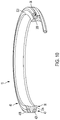
FIG. 10 is a broken-away, perspective view of the seal assembly of FIG. 7, shown in a “free” or uninstalled state;
FIG. 11 is an enlarged, broken-away axial cross-sectional view of the alternative seal assembly; and
FIG. 12 is an enlarged, broken-away axial cross-sectional view of a seal body of the alternative seal assembly.
DETAILED DESCRIPTION OF THE INVENTION
Certain terminology is used in the following description for convenience only and is not limiting. The words “inner”, “inwardly” and “outer”, “outwardly” refer to directions toward and away from, respectively, a designated centerline or a geometric center of an element being described, the particular meaning being readily apparent from the context of the description. Further, as used herein, the words “connected” and “coupled” are each intended to include direct connections between two members without any other members interposed therebetween and indirect connections between members in which one or more other members are interposed therebetween. The terminology includes the words specifically mentioned above, derivatives thereof, and words of similar import.
Referring now to the drawings in detail, wherein like numbers are used to indicate like elements throughout, there is shown in FIGS. 1-12 an axial face seal assembly 10 for sealing a joint J between first and second tubular members 12, 14, respectively, which collectively form a mechanical assembly 11. The mechanical assembly 11 is preferably a swivel joint of a pipe assembly for transporting fluids such as fracking fluid but may be any other assembly of mechanical parts or components utilizing an axial face seal. The first, inner tubular member 12 has a central passage 16 and a generally annular end surface 18 surrounding the passage 16 and the second, outer tubular member 14 has a central passage 20 and a generally annular end surface 22 surrounding the passage 20. The first member end surface 18 faces and is spaced apart along a central axis AC from the second member end surface 22, so as to define a generally annular space or seal “gland” GS, and at least the second tubular member 14 is angularly displaceable about the axis AC with respect to the first tubular member 12. Preferably, the second tubular member 14 further has a collar portion 26 extending axially outwardly from and surrounding the end surface 22, which provides an inner circumferential surface 28 which encloses the radially outer end of the annular gland GS. The seal assembly 10 is disposeable within the gland GS and basically comprises a generally annular seal body 30 formed of a generally compressible polymeric material and at least one backing ring 40, as preferred and shown in FIGS. 1-6, or alternatively two backing rings 40, a first ring 42A and a second ring 42B, as depicted in FIGS. 7-12. In either construction, each backing ring 40 is formed of generally rigid material and is coupled with the seal body 30.
The generally annular seal body 30 is preferably formed of hydrogenated nitrile butadiene rubber (HNBR) or polyurethane plastic but may be formed of any other similar known sealing material. The seal body 30 has opposing inner and outer radial ends 30 a, 30 b, respectively, an inner circumferential surface 31A on the inner end 30 a and an outer circumferential surface 31B on the outer end 30 b. The body 30 also has a first axial end 30 c with a first axial sealing surface 32A disposeable against the first member end surface 18 and a second axial end 30 d with a second axial sealing surface 32B disposeable against the second member end surface 22. Thereby, the sealing surfaces 32A, 32B substantially prevent fluid flow from the central passages 16, 20 through the gland GS, and thus externally of the joint J between the tubular members 12, 14. Further, the seal body 30 also includes at least one recess 34, preferably a single recess 34 as shown in FIGS. 1-6, but may alternatively include two recesses 34 as depicted in FIGS. 7-12, each recess 34 being configured to receive a single backing ring 40.
Specifically, in the preferred construction shown in FIGS. 1-6, the seal body 30 has a single recess 34 configured to receive one backing ring 40 and defined by a generally radial surface 36 extending radially inwardly from the seal body outer radial end 30 b, an outer circumferential surface 37 extending axially inwardly from the second axial end 30 d and an angled activation surface 38 extending generally axially and radially between the radial surface 36 and the circumferential surface 37. With this structure, the first axial sealing surface 32A is located generally between the recess 34 and the inner radial end 30 a, the second axial sealing surface 32B is located generally between the outer circumferential surface 31B and the inner radial end 30 a, and the outer circumferential surface 31B is offset towards the second axial end 30 d and extends axially between the radial surface 36 and the second axial sealing surface 32B. With the single recess 34, the seal body 30 has generally “L-shaped” axial cross-sections.
In the alternative construction shown in FIGS. 7-12, the seal body 30 may be formed having a first recess 35A configured to receive the first backing ring 42A and defined by a first generally radial surface 36A extending radially inwardly from the seal body outer radial end 30 b, a first outer circumferential surface 37A extending axially inwardly from the first axial end 30 c and a first angled activation surface 38A extending generally axially and radially between the radial surface 36A and the circumferential surface 37A. A second recess 35B is configured to receive the second backing ring 42B and is defined by a generally a second radial surface 36B extending radially inwardly from the seal body outer radial end 30 b, a second outer circumferential surface 37B extending axially inwardly from the second axial end 30 d and a second angled activation surface 38B extending generally axially and radially between the radial surface 36B and the circumferential surface 37B. With the structure of the two recesses 35A, 35B, the first axial sealing surface 32A is located generally between the first recess 35A and the inner radial end 30 a, the second axial sealing surface 32B is located generally between the second recess 35B and the inner radial end 30 a, and the outer circumferential surface 31B is centrally located and extends axially between the first and second radial surfaces 36A, 36B. By having the two recesses 34, the alternative construction seal body 30 is generally “T-shaped” and includes a radially extended central portion 31 and two axial shoulder portions 33A, 33B each extending axially outwardly from the central portion 31 in opposing axial directions.
Referring to FIGS. 2-5 and 8-11, each generally annular backing ring 40 is preferably formed of a substantially rigid material, preferably a metallic material such as aluminum bronze, bronze, aluminum, steel, etc., but may alternatively be formed of a rigid thermoplastic material, another rigid polymeric material, a ceramic, or any other appropriate material. Each of the one or two backing rings 40 is disposed at least partially within a separate recess 34 to couple the ring 40 with the seal body 30. Further, each backing ring 40 has opposing inner and outer radial ends 40 a, 40 b, inner and outer axial ends 40 c, 40 d each having a radial surface 41, an inner circumferential surface 43A on the inner radial end 40 a and an outer circumferential surface 43B on the outer radial end 40 b. Preferably, each backing ring 40 further has an angled engagement surface 44 extending axially and radially between the inner radial surface 41 and the inner circumferential surface 43A. Each ring engagement surface 44 is disposed generally against the seal body activation surface 38 of the associated seal body recess 34 or 35A, 35B, such that the activation surface(s) 38 act against the engagement surface(s) 44 during biasing of the rings 40, as described in detail below.
Referring to FIGS. 2, 3, 7 and 8, when the seal assembly 10 is installed within the gland GS, each ring outer axial end 40 d is disposed against the adjacent member end surface 18 or 22, such that the backing ring(s) 40 prevent radially-outward displacement or “extrusion” of the portions of the seal body 30 at the member end surface 18 or 22. More specifically, in the preferred construction, the backing ring 40 is biased axially toward the end surface 18 of the first, inner member 12 when compression of the seal body 30 displaces the seal body activation surface 38 generally axially and outwardly, to thereby enhance the anti-extrusion capability of the backing ring 40. That is, radially-outward compression of the seal body 30 displaces the backing ring 40 axially generally away from the second, outer member end surface 22 and generally toward and against the adjacent first, inner member end surface 18. Similarly in the alternative construction, each of the two backing rings 42A, 42B is biased generally axially toward the associated member end surface 18, 22, respectively, when compression of the seal body 30 displaces the seal body activation surfaces 38 generally axially and outwardly, such that each backing ring 42A, 42B is biased away from the other backing ring 42B, 42A and generally against the associated tubular member end surface 18, 22, respectively.
More specifically, fluid pressure PF exerted on the inner circumferential surface 31A of the seal body 30 tends to compress the seal body 30 generally radially outwardly. Such radial outward compression of the seal body 30 deflects or displaces the angled activation surface(s) 38 generally axially outwardly toward the facing tubular member end surface 18 or 22. Such deflection/displacement of the seal body activation surface(s) 38 pushes or biases the associated backing ring 40 axially toward the associated/adjacent tubular member end surface 18 or 22, as indicated in FIGS. 3 and 9. Thereby, the contact force Fc exerted by each backing ring 40, 42A or 42B against the associated end surface 18 or 22 is increased, which substantially reduces the potential for extrusion of seal material between the ring 40, or rings 42A, 42B, and the tubular members 12, 14.
Referring now to FIGS. 2, 3 and 5, each backing ring 40 is preferably releasably coupled with the seal body 30 by friction, but may alternatively be permanently or semi-permanently coupled by adhesives, fasteners or any other appropriate means. Most preferably, the seal body 30 includes one or two sockets 39, each extending generally radially inwardly from the outer circumferential surface 37 of the recess 34 or of each one of the two recesses 35A, 35B. Each backing ring 40 preferably includes a generally annular projection 46 extending generally radially inwardly from the ring inner radial end 40 a. Each backing ring projection 46 is disposeable within the socket 39 of the associated recess 34, 35A or 35B to thereby releasably couple the backing ring 40 with the seal body 30. Alternatively, the seal body 30 may include at least one and preferably two annular projections (not shown) extending radially outwardly from each outer circumferential surface 37 and each backing ring 40 may include an annular socket (not shown) extending generally radially outwardly from the ring inner end 40 a, with the seal projections being disposeable within the backing ring sockets (structure not depicted).
It will be appreciated by those skilled in the art that changes could be made to the embodiments described above without departing from the broad inventive concept thereof. It is understood, therefore, that this invention is not limited to the particular embodiments disclosed, but it is intended to cover modifications within the spirit and scope of the present invention as generally defined herein and in the appended claims.

Claims (10)

We claim:
1. A seal assembly for sealing between first and second tubular members, each tubular member having a central passage and a generally annular end surface surrounding the passage, the first member passage being fluidly coupled with the second member passage, the first member end surface facing and being spaced apart from the second member end surface along a central axis so as to define an annular gland, and the first member being angularly displaceable about the axis with respect to the second member, the seal assembly comprising:
a generally annular seal body disposeable within the annular gland and formed of a generally compressible polymeric material, the seal body having opposing inner and outer radial ends, a first axial end having a first axial sealing surface disposeable against the first member end surface, a second axial end having a second axial sealing surface disposeable against the second member end surface, and at least one recess defined by a generally radial surface extending radially inwardly from the seal body outer radial end, an outer circumferential surface extending axially inwardly from the first axial end and an angled activation surface extending generally axially and radially between the radial surface and the circumferential surface, the first sealing surface being located generally between the recess and the inner radial end; and
a generally annular backing ring formed of a substantially rigid material and disposed at least partially within the at least one seal recess to couple the backing ring with the seal body, the backing ring having opposing inner and outer radial ends and inner and outer axial ends, the outer axial end being disposeable against the first member end surface such that the backing ring prevents radially outward displacement of the portions of the seal at the first member end surface, the backing ring being biased generally axially toward the first member end surface when compression of the seal body displaces the activation surface generally axially.
2. The seal assembly as recited in claim 1 wherein:
the seal body has one of an annular socket extending generally radially inwardly from the outer circumferential surface and an annular projection extending radially outwardly from the outer circumferential surface; and
the backing ring includes one of an annular projection extending generally inwardly from ring inner radial end and disposeable within the seal socket to releasably couple the backing ring with the seal body and an annular socket extending generally radially outwardly from the ring inner end and the seal body projection is disposed within the backing recess to releasably couple the backing ring with the seal body.
3. The seal assembly as recited in claim 1 wherein:
the seal recess is a first recess defined by a first radial surface, a first circumferential surface and a first activation surface and the seal further includes a second recess defined by a second generally radial surface extending radially inwardly from the seal body outer radial end and spaced axially from the first radial surface, a second outer circumferential surface extending axially inwardly from the second axial end and an second angled activation surface extending generally axially and radially between the second radial surface and the second circumferential surface, the second sealing surface being located generally between the second recess and the seal inner radial end;
the backing ring is a first backing ring; and
the seal assembly further comprises a second generally annular backing ring formed of a substantially rigid material and disposed at least partially within the second recess to couple the second backing ring with the seal, the second backing ring having opposing inner and outer radial ends and inner and outer axial ends, the outer axial end being disposeable against the second member end surface such that the second backing ring prevents radially outward displacement of portions of the seal at the second member end surface, the second backing ring being biased generally axially toward the second member end surface when compression of the seal displaces the second activation surface generally axially.
4. The seal assembly as recited in claim 3 wherein radially-outward compression of the seal body displaces each one of the first and second backing rings axially and away from the other one of the first and second backing rings.
5. The seal assembly as recited in claim 3 wherein the seal has a central outer circumferential surface at the seal outer radial end and extending axially between the first radial surface and the second radial surface.
6. The seal assembly as recited in claim 1 wherein the backing ring has a radial surface at the inner radial end, an inner circumferential surface and an angled engagement surface extending generally axially and radially between the radial surface and the circumferential surface and disposed generally against the seal body activation surface.
7. The seal assembly as recited in claim 1 wherein the seal body is formed of hydrogenated nitrile butadiene rubber (HNBR) or polyurethane plastic and the backing ring is formed of a metallic material or a rigid thermoplastic material.
8. A seal assembly for sealing between first and second tubular members, each tubular member having a central passage and a generally annular end surface surrounding the passage, the first member passage being fluidly coupled with the second member passage, the first member end surface facing and being spaced apart from the second member end surface along a central axis so as to define an annular gland, and the first member being angularly displaceable about the axis with respect to the second member, the seal assembly comprising:
a generally annular seal body disposeable within the annular gland and formed of a generally compressible polymeric material, the seal body having opposing inner and outer radial ends, a first axial end having a first sealing surface disposeable against the first member end surface, a second axial end having a second sealing surface disposeable against the second member end surface, at least one annular recess defined at least partially by a radial surface extending radially inwardly from the outer end and an outer circumferential surface extending axially inwardly from the first axial end, and one of an annular socket extending radially inwardly from the outer circumferential surface and an annular projection extending generally radially outwardly from the outer circumferential surface; and
a generally annular backing ring formed of a substantially rigid material and disposed at least partially within the at least one seal recess to couple the backing ring with the seal body, the backing ring having opposing inner and outer radial ends and inner and outer axial ends, the outer axial end being disposeable against the first member end surface such that the backing ring prevents radially outward displacement of the portions of the seal at the first member end surface, the backing ring including one of an annular projection extending generally radially inwardly from ring inner radial end and disposeable within the seal socket to releasably couple the backing ring with the seal body and an annular socket extending generally radially outwardly from the ring inner radial end and the seal body projection is disposed within the backing ring socket to releasably couple the backing ring with the seal body.
9. The seal assembly as recited in claim 8 wherein:
the seal body recess is partially defined by an angled activation surface extending generally axially and radially between the seal body radial surface and the seal body circumferential surface; and
the backing ring is disposed at least partially against the activation surface such that the backing ring is biased generally axially toward the first member end surface when compression of the seal body displaces the activation surface generally axially.
10. A seal assembly for sealing between first and second tubular members, each tubular member having a central passage and a generally annular end surface surrounding the passage, the first member passage being fluidly coupled with the second member passage, the first member end surface facing and being spaced apart from the second member end surface along a central axis so as to define an annular gland, and the first member being angularly displaceable about the axis with respect to the second member, the seal assembly comprising:
a generally annular seal body disposeable within the annular gland and formed of a generally compressible polymeric material, the seal body having opposing inner and outer radial ends, a first axial end having a first axial sealing surface disposeable against the first member end surface, a second axial end having a second axial sealing surface disposeable against the second member end surface, and at least one recess defined by a generally radial surface extending radially inwardly from the seal body outer radial end, an outer circumferential surface extending axially inwardly from the first axial end and an angled activation surface extending generally axially and radially between the radial surface and the circumferential surface, the first sealing surface being located generally between the recess and the inner radial end; and
a generally annular backing ring formed of a substantially rigid material and disposed at least partially within the at least one seal recess to couple the backing ring with the seal body, the backing ring having opposing inner and outer radial ends and inner and outer axial ends, the outer axial end being disposeable against the first member end surface such that the backing ring prevents radially outward displacement of the portions of the seal at the first member end surface, the backing ring being biased generally axially toward the first member end surface when compression of the seal body displaces the activation surface generally axially;
wherein the seal recess is a first recess defined by a first radial surface, a first circumferential surface and a first activation surface and the seal further includes a second recess defined by a second generally radial surface extending radially inwardly from the seal body outer radial end and spaced axially from the first radial surface, a second outer circumferential surface extending axially inwardly from the second axial end and an second angled activation surface extending generally axially and radially between the second radial surface and the second circumferential surface, the second sealing surface being located generally between the second recess and the seal inner radial end;
wherein the backing ring is a first backing ring; and
wherein the seal assembly further comprises a second generally annular backing ring formed of a substantially rigid material and disposed at least partially within the second recess to couple the second hacking ring with the seal, the second hacking ring having opposing inner and outer radial ends and inner and outer axial ends, the outer axial end being disposeable against the second member end surface such that the second backing ring prevents radially outward displacement of portions of the seal at the second member end surface, the second backing ring being biased generally axially toward the second member end surface when compression of the seal displaces the second activation surface generally axially.
US16/424,579 2018-05-31 2019-05-29 Axial face seal assembly with outwardly-biased backing rings Active US10995860B2 (en)

Priority Applications (1)

Application Number Priority Date Filing Date Title
US16/424,579 US10995860B2 (en) 2018-05-31 2019-05-29 Axial face seal assembly with outwardly-biased backing rings

Applications Claiming Priority (2)

Application Number Priority Date Filing Date Title
US201862678719P 2018-05-31 2018-05-31
US16/424,579 US10995860B2 (en) 2018-05-31 2019-05-29 Axial face seal assembly with outwardly-biased backing rings

Publications (2)

Publication Number Publication Date
US20190368614A1 US20190368614A1 (en) 2019-12-05
US10995860B2 true US10995860B2 (en) 2021-05-04

Family

ID=68692883

Family Applications (1)

Application Number Title Priority Date Filing Date
US16/424,579 Active US10995860B2 (en) 2018-05-31 2019-05-29 Axial face seal assembly with outwardly-biased backing rings

Country Status (2)

Country Link
US (1) US10995860B2 (en)
CN (1) CN110553038A (en)

Cited By (1)

* Cited by examiner, † Cited by third party
Publication number Priority date Publication date Assignee Title
US20220065348A1 (en) * 2020-08-28 2022-03-03 Trelleborg Sealing Solutions Germany Gmbh Swivel seal assembly

Families Citing this family (1)

* Cited by examiner, † Cited by third party
Publication number Priority date Publication date Assignee Title
US11767050B2 (en) * 2020-04-30 2023-09-26 Steering Solutions Ip Holding Corporation Plastic injected rigid splined shaft connection

Citations (30)

* Cited by examiner, † Cited by third party
Publication number Priority date Publication date Assignee Title
US1277975A (en) 1915-08-17 1918-09-03 Ira A Mann Pipe connection.
US2733969A (en) 1956-02-07 Packing seal
US2927830A (en) 1958-09-12 1960-03-08 Internat Packings Corp Piston seal
US2953398A (en) 1956-05-28 1960-09-20 United States Pipe Foundry Pipe joint
US3393400A (en) 1965-07-30 1968-07-16 Navy Usa Calibration method using transducer array with constant pressure plane wave near-field
US3572735A (en) 1969-11-17 1971-03-30 North American Rockwell Captive plastic seal
US3869132A (en) 1973-07-18 1975-03-04 Pressure Science Inc Fire resistant sealing ring combination
US3940155A (en) 1974-09-20 1976-02-24 Borg-Warner Corporation Elastomeric seal
US4062550A (en) * 1975-09-17 1977-12-13 Kabushiki Kaisha Komatsu Seisakusho Seal assembly with backup ring
US4179130A (en) * 1978-02-25 1979-12-18 Firma Intertrac Viehmann & Co. Seal assembly for track-segment pivot
US4756784A (en) 1986-06-02 1988-07-12 United States Pipe And Foundry Company Method of making pipe-joint gasket
US6273231B1 (en) 1998-10-15 2001-08-14 Luk Lamellen Und Kupplungsbau Gmbh Fluid operated clutch disengaging apparatus
US20010024016A1 (en) 1998-05-20 2001-09-27 Kalsi Engineering, Inc. Hydrodynamic rotary seal with opposed tapering seal lips
US20020106923A1 (en) 2001-02-02 2002-08-08 Copeland Daniel A. Device for producing an electrically conductive pipe joint
US6814358B2 (en) 2000-04-20 2004-11-09 Busak + Shamban Deutschland Gmbh Sealing array
US20050062235A1 (en) 2003-09-18 2005-03-24 Cooper Cameron Corporation Annular seal
US20070071938A1 (en) 2005-09-27 2007-03-29 Shigemitsu Kawazoe Seal device for painting machine
US7207606B2 (en) 2004-04-19 2007-04-24 United States Pipe And Foundry Company, Llc Mechanical pipe joint, gasket, and method for restraining pipe spigots in mechanical pipe joint bell sockets
US7774915B2 (en) 2007-05-16 2010-08-17 S & B Technical Products, Inc. Ductile iron pressure fit gasket
US20120023721A1 (en) 2009-04-09 2012-02-02 Piercan Sas Device for the sealed attachment of an interchangeable member in a chamber ring mounted on a wall of a containment cell
US20140203516A1 (en) 2011-04-29 2014-07-24 Onesubsea Ip Uk Limited Seal having stress control groove
US8839874B2 (en) * 2012-05-15 2014-09-23 Baker Hughes Incorporated Packing element backup system
US20150115547A1 (en) 2013-10-24 2015-04-30 Aktiebolaget Skf Seal with Tabs for Retaining Energizing Member
US9120261B2 (en) 2012-02-13 2015-09-01 Cameron International Corporation Seal molding sleeve
US20150285381A1 (en) 2014-04-03 2015-10-08 GM Global Technology Operations LLC Wedge seal gasket
US9194519B2 (en) 2010-08-24 2015-11-24 Mueller International, Llc Gasket for parabolic ramp self restraining bell joint
US10001216B2 (en) 2015-04-07 2018-06-19 Cameron International Corporation Metal end cap seal
US10107434B1 (en) 2015-10-02 2018-10-23 Mcwane, Inc. High deflection Restrained pipe joint
US20190032783A1 (en) 2016-02-03 2019-01-31 Nok Corporation Gasket
US10302200B2 (en) 2017-05-16 2019-05-28 Kalsi Engineering, Inc. Seal for bi-directional rotation and pressure

Family Cites Families (7)

* Cited by examiner, † Cited by third party
Publication number Priority date Publication date Assignee Title
US4811961A (en) * 1988-04-08 1989-03-14 Boliden Allis, Inc. Seal for rotating cylinders such as kilns and the like
US6398223B1 (en) * 2000-08-21 2002-06-04 John Crane Inc. Mechanical face seal
EP3421031A1 (en) * 2006-08-09 2019-01-02 Intarcia Therapeutics, Inc Osmotic delivery systems and piston assemblies
CN104220769B (en) * 2012-03-15 2018-03-30 Skf公司 Rotary chuck seal with inside face sealing surfaces
US9109702B2 (en) * 2013-03-21 2015-08-18 Caterpillar Inc. Boot seal for machine system and method
US9789887B2 (en) * 2015-05-11 2017-10-17 Aktiebolaget Skf Backing ring assembly for railcar axle bearings
US10024435B2 (en) * 2016-05-18 2018-07-17 Kaydon Ring & Seal, Inc. Seal assembly with biasing member retaining pockets

Patent Citations (30)

* Cited by examiner, † Cited by third party
Publication number Priority date Publication date Assignee Title
US2733969A (en) 1956-02-07 Packing seal
US1277975A (en) 1915-08-17 1918-09-03 Ira A Mann Pipe connection.
US2953398A (en) 1956-05-28 1960-09-20 United States Pipe Foundry Pipe joint
US2927830A (en) 1958-09-12 1960-03-08 Internat Packings Corp Piston seal
US3393400A (en) 1965-07-30 1968-07-16 Navy Usa Calibration method using transducer array with constant pressure plane wave near-field
US3572735A (en) 1969-11-17 1971-03-30 North American Rockwell Captive plastic seal
US3869132A (en) 1973-07-18 1975-03-04 Pressure Science Inc Fire resistant sealing ring combination
US3940155A (en) 1974-09-20 1976-02-24 Borg-Warner Corporation Elastomeric seal
US4062550A (en) * 1975-09-17 1977-12-13 Kabushiki Kaisha Komatsu Seisakusho Seal assembly with backup ring
US4179130A (en) * 1978-02-25 1979-12-18 Firma Intertrac Viehmann & Co. Seal assembly for track-segment pivot
US4756784A (en) 1986-06-02 1988-07-12 United States Pipe And Foundry Company Method of making pipe-joint gasket
US20010024016A1 (en) 1998-05-20 2001-09-27 Kalsi Engineering, Inc. Hydrodynamic rotary seal with opposed tapering seal lips
US6273231B1 (en) 1998-10-15 2001-08-14 Luk Lamellen Und Kupplungsbau Gmbh Fluid operated clutch disengaging apparatus
US6814358B2 (en) 2000-04-20 2004-11-09 Busak + Shamban Deutschland Gmbh Sealing array
US20020106923A1 (en) 2001-02-02 2002-08-08 Copeland Daniel A. Device for producing an electrically conductive pipe joint
US20050062235A1 (en) 2003-09-18 2005-03-24 Cooper Cameron Corporation Annular seal
US7207606B2 (en) 2004-04-19 2007-04-24 United States Pipe And Foundry Company, Llc Mechanical pipe joint, gasket, and method for restraining pipe spigots in mechanical pipe joint bell sockets
US20070071938A1 (en) 2005-09-27 2007-03-29 Shigemitsu Kawazoe Seal device for painting machine
US7774915B2 (en) 2007-05-16 2010-08-17 S & B Technical Products, Inc. Ductile iron pressure fit gasket
US20120023721A1 (en) 2009-04-09 2012-02-02 Piercan Sas Device for the sealed attachment of an interchangeable member in a chamber ring mounted on a wall of a containment cell
US9194519B2 (en) 2010-08-24 2015-11-24 Mueller International, Llc Gasket for parabolic ramp self restraining bell joint
US20140203516A1 (en) 2011-04-29 2014-07-24 Onesubsea Ip Uk Limited Seal having stress control groove
US9120261B2 (en) 2012-02-13 2015-09-01 Cameron International Corporation Seal molding sleeve
US8839874B2 (en) * 2012-05-15 2014-09-23 Baker Hughes Incorporated Packing element backup system
US20150115547A1 (en) 2013-10-24 2015-04-30 Aktiebolaget Skf Seal with Tabs for Retaining Energizing Member
US20150285381A1 (en) 2014-04-03 2015-10-08 GM Global Technology Operations LLC Wedge seal gasket
US10001216B2 (en) 2015-04-07 2018-06-19 Cameron International Corporation Metal end cap seal
US10107434B1 (en) 2015-10-02 2018-10-23 Mcwane, Inc. High deflection Restrained pipe joint
US20190032783A1 (en) 2016-02-03 2019-01-31 Nok Corporation Gasket
US10302200B2 (en) 2017-05-16 2019-05-28 Kalsi Engineering, Inc. Seal for bi-directional rotation and pressure

Cited By (1)

* Cited by examiner, † Cited by third party
Publication number Priority date Publication date Assignee Title
US20220065348A1 (en) * 2020-08-28 2022-03-03 Trelleborg Sealing Solutions Germany Gmbh Swivel seal assembly

Also Published As

Publication number Publication date
US20190368614A1 (en) 2019-12-05
CN110553038A (en) 2019-12-10

Similar Documents

Publication Publication Date Title
EP0237672B1 (en) Seal
US5687976A (en) Symmetrical gasket for a pipe joint
US5725219A (en) Mechanical face seal with elastomeric bellows unit and intermeshing drive bands
US6592153B1 (en) High temperature end fitting
US7464942B2 (en) Shaft seal having independent sealing lips
KR940004240A (en) Rotatable mechanical end face seal
US10995860B2 (en) Axial face seal assembly with outwardly-biased backing rings
US9845879B2 (en) High pressure dynamic sealing arrangement
US10215284B2 (en) Flowline divertor seal with spring-energized sealing lips
US8262091B2 (en) Scarf cut backup rings
US5039112A (en) Multi-layer lip seal assembly
US4511152A (en) Self-reinforced face seal
US10794490B2 (en) High pressure seal
US20150115547A1 (en) Seal with Tabs for Retaining Energizing Member
US4063741A (en) Fluid face seal assemblies
US20190331223A1 (en) Axial Face Seal Assembly with Improved Abrasion Resistance
US20140346737A1 (en) Piston seal assembly
US9939067B2 (en) Elastic contact seal
EP0395713B1 (en) Helical seal
US9027928B2 (en) Pumping seal having projections for axially positioning a biasing member
JP2002267021A (en) Elastomer energized rod seal with consolidated backup ring
US20210080008A1 (en) Seal with Pressure Activatable Bead
EP0701074A1 (en) Seal assembly with secondary seal
US20210088143A1 (en) Seal having a Lip Optimized for Low Temperature Applications
US20100084823A1 (en) Hydraulically Balanced Radial Seal

Legal Events

Date Code Title Description
FEPP Fee payment procedure

Free format text: ENTITY STATUS SET TO UNDISCOUNTED (ORIGINAL EVENT CODE: BIG.); ENTITY STATUS OF PATENT OWNER: LARGE ENTITY

AS Assignment

Owner name: AKTIEBOLAGET SKF, SWEDEN

Free format text: ASSIGNMENT OF ASSIGNORS INTEREST;ASSIGNORS:HURST, DANIEL PAUL;MCBRIDE, TADD;RYTHER, TYLER JAMES;AND OTHERS;SIGNING DATES FROM 20190710 TO 20190711;REEL/FRAME:049757/0589

STPP Information on status: patent application and granting procedure in general

Free format text: DOCKETED NEW CASE - READY FOR EXAMINATION

STPP Information on status: patent application and granting procedure in general

Free format text: NOTICE OF ALLOWANCE MAILED -- APPLICATION RECEIVED IN OFFICE OF PUBLICATIONS

STPP Information on status: patent application and granting procedure in general

Free format text: NOTICE OF ALLOWANCE MAILED -- APPLICATION RECEIVED IN OFFICE OF PUBLICATIONS

STPP Information on status: patent application and granting procedure in general

Free format text: PUBLICATIONS -- ISSUE FEE PAYMENT RECEIVED

STPP Information on status: patent application and granting procedure in general

Free format text: PUBLICATIONS -- ISSUE FEE PAYMENT VERIFIED

STCF Information on status: patent grant

Free format text: PATENTED CASE