US10993835B2 - Device for packaging and dispensing a substance for ophthalmic use - Google Patents
Device for packaging and dispensing a substance for ophthalmic use Download PDFInfo
- Publication number
- US10993835B2 US10993835B2 US16/033,426 US201816033426A US10993835B2 US 10993835 B2 US10993835 B2 US 10993835B2 US 201816033426 A US201816033426 A US 201816033426A US 10993835 B2 US10993835 B2 US 10993835B2
- Authority
- US
- United States
- Prior art keywords
- valve
- dispensing
- product
- accessory
- membrane
- Prior art date
- Legal status (The legal status is an assumption and is not a legal conclusion. Google has not performed a legal analysis and makes no representation as to the accuracy of the status listed.)
- Active, expires
Links
- 238000004806 packaging method and process Methods 0.000 title claims abstract description 22
- 239000000126 substance Substances 0.000 title abstract 3
- 229920001971 elastomer Polymers 0.000 claims abstract description 36
- 239000000806 elastomer Substances 0.000 claims abstract description 36
- 239000000463 material Substances 0.000 claims abstract description 29
- 229920000052 poly(p-xylylene) Polymers 0.000 claims abstract description 25
- 239000012530 fluid Substances 0.000 claims abstract description 13
- 239000000839 emulsion Substances 0.000 claims abstract description 5
- 239000000725 suspension Substances 0.000 claims abstract description 4
- 239000012528 membrane Substances 0.000 claims description 80
- 150000003180 prostaglandins Chemical class 0.000 claims description 14
- PPBRXRYQALVLMV-UHFFFAOYSA-N Styrene Chemical compound C=CC1=CC=CC=C1 PPBRXRYQALVLMV-UHFFFAOYSA-N 0.000 claims description 10
- 229920002725 thermoplastic elastomer Polymers 0.000 claims description 10
- 230000002093 peripheral effect Effects 0.000 claims description 9
- 229920001296 polysiloxane Polymers 0.000 claims description 8
- 238000012545 processing Methods 0.000 claims description 6
- 239000004433 Thermoplastic polyurethane Substances 0.000 claims description 5
- 238000001914 filtration Methods 0.000 claims description 5
- 229920000098 polyolefin Polymers 0.000 claims description 5
- 229920002803 thermoplastic polyurethane Polymers 0.000 claims description 5
- 239000011248 coating agent Substances 0.000 claims description 4
- 238000000576 coating method Methods 0.000 claims description 4
- 238000003466 welding Methods 0.000 claims description 4
- 239000003470 adrenal cortex hormone Substances 0.000 claims description 3
- 230000003110 anti-inflammatory effect Effects 0.000 claims description 3
- RKHQGWMMUURILY-UHRZLXHJSA-N cortivazol Chemical compound C([C@H]1[C@@H]2C[C@H]([C@]([C@@]2(C)C[C@H](O)[C@@H]1[C@@]1(C)C2)(O)C(=O)COC(C)=O)C)=C(C)C1=CC1=C2C=NN1C1=CC=CC=C1 RKHQGWMMUURILY-UHRZLXHJSA-N 0.000 claims description 3
- 238000000465 moulding Methods 0.000 claims description 3
- 230000003637 steroidlike Effects 0.000 claims description 3
- 238000004519 manufacturing process Methods 0.000 claims description 2
- 230000012010 growth Effects 0.000 description 23
- 239000000243 solution Substances 0.000 description 13
- GGXICVAJURFBLW-CEYXHVGTSA-N latanoprost Chemical compound CC(C)OC(=O)CCC\C=C/C[C@H]1[C@@H](O)C[C@@H](O)[C@@H]1CC[C@@H](O)CCC1=CC=CC=C1 GGXICVAJURFBLW-CEYXHVGTSA-N 0.000 description 12
- 229960001160 latanoprost Drugs 0.000 description 11
- 210000000887 face Anatomy 0.000 description 8
- 238000003825 pressing Methods 0.000 description 7
- 238000004458 analytical method Methods 0.000 description 6
- 239000007788 liquid Substances 0.000 description 6
- 230000003993 interaction Effects 0.000 description 5
- 230000000295 complement effect Effects 0.000 description 4
- 229940079593 drug Drugs 0.000 description 4
- 239000003814 drug Substances 0.000 description 4
- 230000000694 effects Effects 0.000 description 4
- 230000036512 infertility Effects 0.000 description 4
- 239000011159 matrix material Substances 0.000 description 4
- 239000003755 preservative agent Substances 0.000 description 4
- WEVYAHXRMPXWCK-UHFFFAOYSA-N Acetonitrile Chemical compound CC#N WEVYAHXRMPXWCK-UHFFFAOYSA-N 0.000 description 3
- 229920002943 EPDM rubber Polymers 0.000 description 3
- 208000010412 Glaucoma Diseases 0.000 description 3
- 239000002174 Styrene-butadiene Substances 0.000 description 3
- MTAZNLWOLGHBHU-UHFFFAOYSA-N butadiene-styrene rubber Chemical compound C=CC=C.C=CC1=CC=CC=C1 MTAZNLWOLGHBHU-UHFFFAOYSA-N 0.000 description 3
- 238000004128 high performance liquid chromatography Methods 0.000 description 3
- 230000004410 intraocular pressure Effects 0.000 description 3
- 238000002483 medication Methods 0.000 description 3
- 239000000203 mixture Substances 0.000 description 3
- 239000011115 styrene butadiene Substances 0.000 description 3
- 229920003048 styrene butadiene rubber Polymers 0.000 description 3
- 230000000844 anti-bacterial effect Effects 0.000 description 2
- 230000008901 benefit Effects 0.000 description 2
- AQOKCDNYWBIDND-FTOWTWDKSA-N bimatoprost Chemical compound CCNC(=O)CCC\C=C/C[C@H]1[C@@H](O)C[C@@H](O)[C@@H]1\C=C\[C@@H](O)CCC1=CC=CC=C1 AQOKCDNYWBIDND-FTOWTWDKSA-N 0.000 description 2
- 238000004587 chromatography analysis Methods 0.000 description 2
- 230000007423 decrease Effects 0.000 description 2
- 239000002997 ophthalmic solution Substances 0.000 description 2
- -1 polyethylene Polymers 0.000 description 2
- 229920002379 silicone rubber Polymers 0.000 description 2
- 229960004458 tafluprost Drugs 0.000 description 2
- WSNODXPBBALQOF-VEJSHDCNSA-N tafluprost Chemical compound CC(C)OC(=O)CCC\C=C/C[C@H]1[C@@H](O)C[C@@H](O)[C@@H]1\C=C\C(F)(F)COC1=CC=CC=C1 WSNODXPBBALQOF-VEJSHDCNSA-N 0.000 description 2
- MKPLKVHSHYCHOC-AHTXBMBWSA-N travoprost Chemical compound CC(C)OC(=O)CCC\C=C/C[C@H]1[C@@H](O)C[C@@H](O)[C@@H]1\C=C\[C@@H](O)COC1=CC=CC(C(F)(F)F)=C1 MKPLKVHSHYCHOC-AHTXBMBWSA-N 0.000 description 2
- LSIXBBPOJBJQHN-UHFFFAOYSA-N 2,3-Dimethylbicyclo[2.2.1]hept-2-ene Chemical compound C1CC2C(C)=C(C)C1C2 LSIXBBPOJBJQHN-UHFFFAOYSA-N 0.000 description 1
- VRBFTYUMFJWSJY-UHFFFAOYSA-N 28804-46-8 Chemical compound ClC1CC(C=C2)=CC=C2C(Cl)CC2=CC=C1C=C2 VRBFTYUMFJWSJY-UHFFFAOYSA-N 0.000 description 1
- XQFRJNBWHJMXHO-RRKCRQDMSA-N IDUR Chemical compound C1[C@H](O)[C@@H](CO)O[C@H]1N1C(=O)NC(=O)C(I)=C1 XQFRJNBWHJMXHO-RRKCRQDMSA-N 0.000 description 1
- 239000007836 KH2PO4 Substances 0.000 description 1
- NBIIXXVUZAFLBC-UHFFFAOYSA-N Phosphoric acid Chemical compound OP(O)(O)=O NBIIXXVUZAFLBC-UHFFFAOYSA-N 0.000 description 1
- 239000004698 Polyethylene Substances 0.000 description 1
- 238000010521 absorption reaction Methods 0.000 description 1
- 230000009471 action Effects 0.000 description 1
- 230000000845 anti-microbial effect Effects 0.000 description 1
- 239000000607 artificial tear Substances 0.000 description 1
- 230000003416 augmentation Effects 0.000 description 1
- 229960000686 benzalkonium chloride Drugs 0.000 description 1
- CADWTSSKOVRVJC-UHFFFAOYSA-N benzyl(dimethyl)azanium;chloride Chemical compound [Cl-].C[NH+](C)CC1=CC=CC=C1 CADWTSSKOVRVJC-UHFFFAOYSA-N 0.000 description 1
- 229960002470 bimatoprost Drugs 0.000 description 1
- 230000004397 blinking Effects 0.000 description 1
- 230000000903 blocking effect Effects 0.000 description 1
- 239000003795 chemical substances by application Substances 0.000 description 1
- 239000000356 contaminant Substances 0.000 description 1
- 238000011109 contamination Methods 0.000 description 1
- 239000002537 cosmetic Substances 0.000 description 1
- 238000001514 detection method Methods 0.000 description 1
- 238000011161 development Methods 0.000 description 1
- 238000010586 diagram Methods 0.000 description 1
- 230000003467 diminishing effect Effects 0.000 description 1
- 238000006073 displacement reaction Methods 0.000 description 1
- 210000000744 eyelid Anatomy 0.000 description 1
- 210000003811 finger Anatomy 0.000 description 1
- 230000036571 hydration Effects 0.000 description 1
- 238000006703 hydration reaction Methods 0.000 description 1
- 229960004716 idoxuridine Drugs 0.000 description 1
- 229940112534 lumigan Drugs 0.000 description 1
- 230000014759 maintenance of location Effects 0.000 description 1
- 230000007257 malfunction Effects 0.000 description 1
- 238000005259 measurement Methods 0.000 description 1
- 238000000034 method Methods 0.000 description 1
- 238000011169 microbiological contamination Methods 0.000 description 1
- 229910000402 monopotassium phosphate Inorganic materials 0.000 description 1
- 235000019796 monopotassium phosphate Nutrition 0.000 description 1
- 239000000041 non-steroidal anti-inflammatory agent Substances 0.000 description 1
- 239000000825 pharmaceutical preparation Substances 0.000 description 1
- 229940127557 pharmaceutical product Drugs 0.000 description 1
- 235000011007 phosphoric acid Nutrition 0.000 description 1
- 229920000573 polyethylene Polymers 0.000 description 1
- GNSKLFRGEWLPPA-UHFFFAOYSA-M potassium dihydrogen phosphate Chemical compound [K+].OP(O)([O-])=O GNSKLFRGEWLPPA-UHFFFAOYSA-M 0.000 description 1
- 230000002335 preservative effect Effects 0.000 description 1
- 230000008569 process Effects 0.000 description 1
- 230000035755 proliferation Effects 0.000 description 1
- 230000002040 relaxant effect Effects 0.000 description 1
- 238000011160 research Methods 0.000 description 1
- 238000010008 shearing Methods 0.000 description 1
- 238000001179 sorption measurement Methods 0.000 description 1
- 238000003860 storage Methods 0.000 description 1
- 238000012360 testing method Methods 0.000 description 1
- 210000003813 thumb Anatomy 0.000 description 1
- 230000007704 transition Effects 0.000 description 1
- 229940113006 travatan Drugs 0.000 description 1
- 229960002368 travoprost Drugs 0.000 description 1
- 229940002639 xalatan Drugs 0.000 description 1
Images


Classifications
-
- A—HUMAN NECESSITIES
- A61—MEDICAL OR VETERINARY SCIENCE; HYGIENE
- A61F—FILTERS IMPLANTABLE INTO BLOOD VESSELS; PROSTHESES; DEVICES PROVIDING PATENCY TO, OR PREVENTING COLLAPSING OF, TUBULAR STRUCTURES OF THE BODY, e.g. STENTS; ORTHOPAEDIC, NURSING OR CONTRACEPTIVE DEVICES; FOMENTATION; TREATMENT OR PROTECTION OF EYES OR EARS; BANDAGES, DRESSINGS OR ABSORBENT PADS; FIRST-AID KITS
- A61F9/00—Methods or devices for treatment of the eyes; Devices for putting-in contact lenses; Devices to correct squinting; Apparatus to guide the blind; Protective devices for the eyes, carried on the body or in the hand
- A61F9/0008—Introducing ophthalmic products into the ocular cavity or retaining products therein
- A61F9/0026—Ophthalmic product dispenser attachments to facilitate positioning near the eye
-
- A—HUMAN NECESSITIES
- A61—MEDICAL OR VETERINARY SCIENCE; HYGIENE
- A61F—FILTERS IMPLANTABLE INTO BLOOD VESSELS; PROSTHESES; DEVICES PROVIDING PATENCY TO, OR PREVENTING COLLAPSING OF, TUBULAR STRUCTURES OF THE BODY, e.g. STENTS; ORTHOPAEDIC, NURSING OR CONTRACEPTIVE DEVICES; FOMENTATION; TREATMENT OR PROTECTION OF EYES OR EARS; BANDAGES, DRESSINGS OR ABSORBENT PADS; FIRST-AID KITS
- A61F9/00—Methods or devices for treatment of the eyes; Devices for putting-in contact lenses; Devices to correct squinting; Apparatus to guide the blind; Protective devices for the eyes, carried on the body or in the hand
- A61F9/0008—Introducing ophthalmic products into the ocular cavity or retaining products therein
-
- A—HUMAN NECESSITIES
- A61—MEDICAL OR VETERINARY SCIENCE; HYGIENE
- A61M—DEVICES FOR INTRODUCING MEDIA INTO, OR ONTO, THE BODY; DEVICES FOR TRANSDUCING BODY MEDIA OR FOR TAKING MEDIA FROM THE BODY; DEVICES FOR PRODUCING OR ENDING SLEEP OR STUPOR
- A61M35/00—Devices for applying media, e.g. remedies, on the human body
- A61M35/003—Portable hand-held applicators having means for dispensing or spreading integral media
-
- B—PERFORMING OPERATIONS; TRANSPORTING
- B29—WORKING OF PLASTICS; WORKING OF SUBSTANCES IN A PLASTIC STATE IN GENERAL
- B29D—PRODUCING PARTICULAR ARTICLES FROM PLASTICS OR FROM SUBSTANCES IN A PLASTIC STATE
- B29D22/00—Producing hollow articles
-
- A—HUMAN NECESSITIES
- A61—MEDICAL OR VETERINARY SCIENCE; HYGIENE
- A61M—DEVICES FOR INTRODUCING MEDIA INTO, OR ONTO, THE BODY; DEVICES FOR TRANSDUCING BODY MEDIA OR FOR TAKING MEDIA FROM THE BODY; DEVICES FOR PRODUCING OR ENDING SLEEP OR STUPOR
- A61M2205/00—General characteristics of the apparatus
- A61M2205/33—Controlling, regulating or measuring
- A61M2205/3331—Pressure; Flow
-
- A—HUMAN NECESSITIES
- A61—MEDICAL OR VETERINARY SCIENCE; HYGIENE
- A61M—DEVICES FOR INTRODUCING MEDIA INTO, OR ONTO, THE BODY; DEVICES FOR TRANSDUCING BODY MEDIA OR FOR TAKING MEDIA FROM THE BODY; DEVICES FOR PRODUCING OR ENDING SLEEP OR STUPOR
- A61M2205/00—General characteristics of the apparatus
- A61M2205/75—General characteristics of the apparatus with filters
- A61M2205/7536—General characteristics of the apparatus with filters allowing gas passage, but preventing liquid passage, e.g. liquophobic, hydrophobic, water-repellent membranes
-
- Y—GENERAL TAGGING OF NEW TECHNOLOGICAL DEVELOPMENTS; GENERAL TAGGING OF CROSS-SECTIONAL TECHNOLOGIES SPANNING OVER SEVERAL SECTIONS OF THE IPC; TECHNICAL SUBJECTS COVERED BY FORMER USPC CROSS-REFERENCE ART COLLECTIONS [XRACs] AND DIGESTS
- Y10—TECHNICAL SUBJECTS COVERED BY FORMER USPC
- Y10T—TECHNICAL SUBJECTS COVERED BY FORMER US CLASSIFICATION
- Y10T29/00—Metal working
- Y10T29/49—Method of mechanical manufacture
- Y10T29/49405—Valve or choke making
Definitions
- the invention relates to a device for packaging and dispensing drops of a product for ophthalmic use, generally fluid, semi-fluid or, emulsion or oily solution.
- These devices are used especially in the pharmaceutical, cosmetic and food fields, and for some more particularly in the ophthalmologic field.
- delivering one or more drops of product for the great majority of this type of devices is done by squeezing the bottle containing the product between the thumb and the index finger.
- ophthalmic solutions irrespective of their function (treating an ocular condition, cicatrisation, hydration, etc.), are sold in a polyethylene packaging vial equipped with a drop-counting nozzle for dispensing directly into the eye.
- antimicrobial preservative agents introduced as a mixture to the solution.
- antimicrobial preservative agents benzalkonium chloride for example, have the major disadvantage of being aggressive to eyes.
- the solutions described employ either an antibacterial filter, or systems comprising ball-and-spring valves, or antibacterial materials, or more particularly elastomer valves.
- Document FR 2873358 describes a device in which the product is expelled via a flexible nozzle with which the container is fitted.
- the flexible nozzle forms a small reservoir called a dispensing chamber and is located between two non-return valves.
- a first valve is placed at the level of the reservoir or medication vial and opens in the direction of the dispensing chamber.
- the second valve of annular form, is placed after the dispensing chamber and opens in the direction of the dispensing end of the nozzle. Under the effect of pressure created by squeezing the walls of the flexible nozzle at the level of the dispensing chamber, the liquid is expelled towards the opening of the device via the second valve.
- the device When the squeezing pressure is relaxed, under the effect of its elasticity, the dispensing chamber regains its initial form and opens the first valve by letting a new dose of product fill the dispensing chamber, while the second valve closes.
- the device also comprises a valve at the level of the air intake filter. These valves are made of silicone.
- silicone elastomers are often used because of their properties recognised for pharmaceutical usage (materials inscribed in the pharmacopoeia).
- Analogs of prostaglandin are medications used exclusively in ophthalmology for treating glaucoma, a condition often linked to excessively high intraocular pressure (IOP).
- IOP intraocular pressure
- Prostaglandin in particular makes for easier flow of the aqueous humour via uveoscleral flow. Research has revealed a molecule which reproduces this effect locally. These medications were sold for the first time in 1996.
- Latanoprost (Xalatan, by Pfizer) was the first prostaglandin developed for treating glaucoma and proves efficacious for reducing IOP with daily application at bedtime. Normally during the day the aqueous humour flows mostly through the trabeculum and a little via the uveoscleral channel. However, during the night it mostly uses the uveoscleral channel. In a low dose, latanoprost increases evacuation via the uveoscleral channel for a long period and needs a single daily application only.
- prostaglandin of the same category are travoprost (Travatan, by Alcon), bimatoprost (Lumigan, by Allergan) and tafluprost (Taflotan, by Santen).
- An aim of the invention is to provide a dispensing accessory for a device for packaging and dispensing of a product for ophthalmic use, in particular a product occurring within the scope of treatment against glaucoma, comprising an analog of prostaglandin, a product comprising a corticoid or a product comprising a non-steroidal anti-inflammatory, which dispenses clean or sterile drops of product frequently and repetitively, and which ensures better packaging of the product.
- a device for packaging and dispensing drops of a product for ophthalmic use, generally fluid, semi-fluid or in suspension, emulsion or oily solution, comprising a dispensing accessory comprising a first valve made of elastomer material allowing the product to pass through when the dispensing accessory is stressed without allowing outside air to move in the reverse direction when the dispensing accessory is relaxed, characterized in that the first valve is covered in a layer of parylene.
- a renewal and filtration assembly for air entering the container after dispensing a portion or dose of product, comprising a second valve made of elastomer material and covered in a layer of parylene, allowing outside air to enter said container when the dispensing accessory is relaxed without allowing the product or substantially the air contained inside the container to exit when the dispensing accessory is stressed,
- the second valve has a form comprising:
- the first valve has a hat shape, comprising:
- the first and/or second valve(s) has (have) a substantially plane general circular form delimited by an outer rim and is (are) adapted to allow passage of the product:
- the thickness of the first and/or second valve(s) increases between the central area and the outer rim
- the first and/or second valve(s) at rest has a curve profile and/or having at least one angle
- first and/or second valve(s) has at least one circumferential protuberance extending over at least one of the faces of the first and/or of the second valve(s),
- the first valve has a substantially plane annular form delimited by:
- the elastomer material of the first and/or second valve(s) is silicone
- the elastomer material of the first and/or second valve(s) is thermoplastic elastomer with a polyolefin base, or styrene-based thermoplastic elastomer or thermoplastic polyurethane,
- the dispensing accessory is a dispensing accessory of calibrated drops comprising:
- the form-holding means comprising:
- the dispensing chamber has a cross-section of general trapezoid form, and/or
- the part of the supple membrane delimiting the dispensing chamber forms a generally prismatic piece which comprises two ends, each having an area of lesser thickness.
- the invention also relates to use of such a device for packaging and dispensing of calibrated drops of a product for ophthalmic use, in particular comprising an analog of prostaglandin, a corticoid or a non-steroidal anti-inflammatory.
- the invention further relates to a process for manufacture of such a device, comprising:
- FIG. 1 a is a view in longitudinal section illustrating a first, respectively a second, embodiment of the device for packaging and dispensing a product for ophthalmic use comprising a dispensing accessory according to the invention;
- FIG. 2 is a three-dimensional view of a central piece forming a rigid core of the dispensing accessory of FIGS. 1 a and 1 b;
- FIG. 3 a is a three-dimensional view of a supple membrane of the dispensing accessory illustrating the first, respectively second, embodiment of the device according to the invention
- FIG. 4 a is a view in longitudinal section of the supple membrane of FIG. 3 a , respectively 3 b;
- FIG. 5 is a three-dimensional view of an outer piece forming a second rigid piece illustrating the first embodiment of the device according to the invention
- FIG. 6 a is a view in longitudinal section of the outer piece of FIG. 5 ;
- FIG. 6 b is a view in longitudinal section of the outer piece forming a second rigid piece illustrating the second embodiment of the device according to the invention
- FIG. 7 is a partial view in longitudinal section illustrating a variant of the second embodiment of the device according to the invention.
- FIG. 8 is a partial view in longitudinal section of a dispensing accessory illustrating a third embodiment of a device according to the invention.
- FIG. 9 a is a view in section according to a section of the supple membrane of FIG. 3 a , at the level of the dispensing chamber;
- FIG. 9 b is a sectional view according to a section of the dispensing accessory illustrating the second embodiment of the device according to the invention.
- FIGS. 10 a to 10 c are diagrams showing deformation of a dispensing chamber of the dispensing accessory illustrating the device according to the invention
- FIGS. 11 a to 11 c schematically illustrate several variant embodiments for filling a dispensing chamber of the dispensing accessory illustrating the device according to the invention
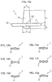
- FIGS. 12 a to 12 h schematically illustrate several variant embodiments of a first valve illustrating the device according to the invention
- FIGS. 13 a to 13 g schematically illustrate several variant embodiments of a second valve illustrating the device according to the invention.
- FIGS. 14 a to 14 c and 15 a to 15 c illustrate results of analysis by chromatography for a valve according to the prior art and a valve illustrating a device according to the invention.
- FIGS. 1 a and 1 b describe a device for packaging and dispensing product for ophthalmic use 1 comprising a dispensing accessory 7 .
- FIG. 1 a respectively 1 b , illustrates a first, respectively a second, embodiment of a device. The characteristics of these two embodiments can be combined.
- the device for packaging and dispensing 1 comprises a container 8 .
- the container 8 is closed at one of its ends by a base 4 comprising means for air intake and filtration. These air intake and filtration means introduce air to the enclosure of the container 8 as the product initially contained in said enclosure is dispensed. As the incoming air is being filtered, this ensures the cleanness or sterility of the product remaining in the enclosure of the container 8 .
- the container 8 has an opening and the dispensing accessory 7 obstructing said opening.
- the dispensing accessory 7 and illustrating the first, respectively second embodiment of FIG. 1 a , respectively 1 b , comprises a central piece forming a rigid core 6 on which coaxially fits a supple membrane 20 , a second rigid piece 10 comprising at least one growth 101 , and a first valve 5 .
- a removable stopper 2 completes the device for packaging and dispensing 1 by covering the dispensing accessory 7 to protect it when the device 1 is not in use.
- the rigid core 6 shown in FIG. 2 in three dimension, extends longitudinally and comprises at one end a base 65 open to the enclosure of the container 8 when said base 65 is mounted tightly in the opening of said container 8 .
- a shoulder 66 connects the base 65 to a first section 63 .
- the shoulder 66 comprises an annular cavity at the base of which continuous orifices 64 are arranged.
- the number and form of these orifices 64 can vary and be adapted to the product for ophthalmic use which is intended to be contained in the container 8 and be dispensed by way of the dispensing accessory 7 .
- the orifices 64 form a passage between the interior of the base 65 and the exterior.
- the first section 63 extends longitudinally via a second section 62 of cross-section smaller than a cross-section of the first section 63 .
- the second section 62 extends longitudinally as far as an opposite end 61 of the rigid core 6 relative to the base 65 .
- the supple membrane 20 illustrating the first embodiment is shown in FIG. 3 a according to a three-dimensional view and FIG. 4 a according to a view in section. It has a substantially cylindrical form and extends longitudinally between an end 25 and an end 24 .
- the supple membrane 20 comprises a coaxial recess 23 of cylindrical form and extending longitudinally between the two ends 24 and 25 .
- the supple membrane 20 comprises at least one chamber 22 , called a dosage membrane, arranged in a thickness of the wall of the membrane and open to the recess 23 .
- the recess 23 comprises a surface 231 .
- the dispensing chamber 22 has, in cross-section, an overall trapezoid form whereof a small base forms the opening in the recess 23 which extends along a first portion of a periphery of the recess 23 .
- the surface 231 opposite extends over a second portion of the periphery of the recess 23 complementary to the first portion of the periphery of said recess 23 .
- the dispensing chamber 22 is delimited centrifugally by a part 21 of the supple membrane.
- This part 21 forms a piece generally of prismatic form. It is elastically deformable and comprises at each of its ends an area of lesser thickness 211 , 212 . In this way, pressing on the part 21 enables quasi-vertical displacement of the prismatic piece in the dispensing chamber 22 and reduces force to be provided when the device is used to distribute a dose or drop of product contained in the enclosure of the container 8 .
- the supple membrane 20 illustrating the second embodiment is shown in FIG. 3 b according to a three-dimensional view, in FIG. 4 b according to a view in section. It differs from the supple membrane illustrating the first embodiment in that it comprises two diametrically opposed dosing chambers 22 .
- the second rigid piece 10 is inside the supple membrane 20 which when mounted is fitted onto the rigid core 6 and onto the second piece 10 .
- the supple membrane 20 comprises a skirt 213 covering an intermediate part 108 of the second piece 10 .
- the growth 101 is then sandwiched between the supple membrane 20 and a portion of the second section 62 of the rigid core 6 .
- the supple membrane 20 is glued or welded onto an outer surface of the growth 101 , ensuring that it cannot deform during use.
- the recess 23 has a greater diameter than between the area 211 and the end 24 .
- the area corresponding to the dosing chambers 22 is therefore included in the recess 23 .
- the dosing chambers 22 are always limited both by the part 21 and by a portion of the second section 62 .
- the two other walls extending longitudinally from the dispensing chamber are constituted by portions of lateral walls of two growths 101 from the second rigid piece 10 .
- the second rigid piece 10 illustrating the first embodiment, shown in FIGS. 5 and 6 a comprises at the level of a first end a base 104 , open to the side of the first end.
- This base 104 is surmounted in the longitudinal direction by a hollow intermediate part 108 , connected to the base 104 by a shoulder 107 .
- the shoulder 107 comprises a hollow 106 whereof an opening is oriented to the interior of the base 104 so as to also terminate in a conduit 105 arranged longitudinally on an inner wall 109 of the intermediate part 108 .
- the intermediate part 108 terminates by an opening 103 forming a second end 110 of the second rigid piece 10 and at the level of which the conduit 105 terminates.
- the opening 103 and the conduit 105 connect each dispensing chamber 22 to the dedicated hollow 106 .
- a rigid growth 101 extends longitudinally projecting from the second end 110 .
- the growth 101 comprises an inner face 102 of concave semi-circular form.
- the growth can be of form in cross-section in an arc of a circle having a thickness E of between 0.5 and 1.5 mm.
- the growth 101 is located diametrically opposite relative to the conduit 105 .
- the second rigid piece 10 according to the second embodiment is illustrated in FIG. 6 b . It has two rigid growths 101 extending longitudinally projecting from the second end 110 .
- the growths 101 comprise an inner face 102 of concave semi-circular form.
- the growths 101 have a form in cross-section in an arc of a circle having a thickness E.
- the dosing chambers 22 extend into the two annular sections located between the growths 101 . Longitudinal faces of width E of the growths 101 constitute walls of the dosing chambers 22 .
- FIG. 1 a shows an assembly of the dispensing accessory 7 illustrating a first embodiment of the device.
- a first valve 5 here made of elastically deformable elastomer flexible material covered in a layer of parylene, covering the orifices 64 .
- the second rigid piece 10 is fitted to slide on the rigid core 6 such that the base 104 of the second rigid piece 10 covers the base 65 of the rigid core 6 .
- the first valve 5 is sandwiched between the shoulders 66 and 107 of the rigid core 6 and of the second rigid piece 10 respectively.
- the first valve 5 can open by deformation in the hollow 106 of the second rigid piece 10 , releasing a passage from at least one of the orifices 64 of the rigid core 6 .
- the resulting fitting is tight, since the base 104 is complementary to the base 65 , and therefore the intermediate part 108 of the second rigid piece is complementary to the first section 63 of the rigid core 6 . Keeping the second rigid piece 10 and of the rigid core 6 in place is ensured by clipping, adhesion and/or welding.
- the supple membrane 20 is then fitted to slide on the second section 62 of the rigid core 6 and the growth 101 of the second rigid piece 10 , until the end 25 comes into contact on the second end 110 of the intermediate part 108 of the second rigid piece 10 and on an apex of the first section 63 of the rigid core 6 . Therefore, the at least one dispensing chamber 22 is delimited by the part 21 of the supple membrane 20 and by a first portion 621 of the periphery of the second section 62 .
- the surface 231 of the supple membrane is in contact with a second portion 622 of the periphery of the rigid core, second portion 622 complementary to the first portion 621 .
- the supple membrane 20 is sandwiched longitudinally between the growth 101 of the second rigid piece 10 , whereof the inner face 102 is supported on an outer surface of the supple membrane, and the second section 62 of the rigid core 6 . So, the surface 231 of the supple membrane is in permanent contact with the second portion 622 of the periphery of the rigid core. Also, the inner face 102 can be glued or welded onto the outer surface of the supple membrane 20 . So, the growth 101 extends over a distance equivalent to a longitudinal dimension of the dispensing chamber 22 and is located diametrically opposite said dispensing chamber. Also, the conduit 105 terminates in the dispensing chamber 22 to feed it following dispensing by said dispensing chamber of a dose or drop of product to be dispensed.
- the dispensing accessory 7 assembled in this way is then mounted tightly on the opening of the container 8 .
- Assembling the dispensing accessory 7 illustrating the second embodiment of the device is done equivalently to the particular features of the second rigid piece 10 and of the supple membrane 20 . So the supple membrane 20 now covers the intermediate part 108 of the second rigid piece 10 .
- the end 24 of the supple membrane 20 is a leaktight manner with a surface of the end 61 of the rigid core 6 .
- the product contained in the corresponding dispensing chamber 22 is put under pressure. Due to the presence of the first valve 5 , the product to be dispensed cannot return to the enclosure of the container 8 .
- the end 24 of the supple membrane deforms by unsticking from the surface of the end 61 of the rigid core 6 , letting said product to be dispensed be dispensed. Once the product is expelled, the end 24 returns to the rest position on the end 61 .
- the first valve 5 is made by a first moulding step of elastomer material, and by a second step for processing the valve with parylene to cover its surface with a coating of parylene, preferably parylene C.
- the elastomer material can be silicone.
- the elastomer material can be thermoplastic elastomer with polyolefin base, such as ethylene-propylene-diene-monomer.
- the elastomer material can be styrene-based thermoplastic elastomer, for example styrene-butadiene or styrene-ethylene-butylene or styrene-ethylene-propylene.
- the material can be thermoplastic polyurethane.
- the first valve 5 has a substantially plane general annular form of an outer diameter D whereof the value is for example between 11 and 20 mm, for example between 13 and 17 mm, for example 15 mm.
- the annular form of the first valve 5 is also delimited by an inner rim 53 of inner diameter d between 5 and 10 mm, for example between 6.5 and 8.5 mm, for example 7.5 mm.
- the thickness of the first valve 5 can be for example between 0.25 and 2.5 mm, for example 0.5 and 1.5 mm.
- the form of the first valve 5 has at least one circumferential protuberance extending over at least one of the faces of the first valve 5 .
- first valve 5 shown in FIGS. 12 a to 12 g are adapted to allow passage of the product for ophthalmic use by deformation at the level of a central opening, an outer rim 52 of the valve 5 being held in position by forces applied to either side of the latter. Such operation is illustrated by the figures relative to the second embodiment.
- FIG. 12 a illustrates an annular form 51 having a convex peripheral circumferential protuberance at the level of the outer rim 52 of the first valve 5 , of maximal thickness of 0.5 mm, on a face of the first valve 5 .
- the form also has a central circumferential protuberance at the level of the inner rim 53 , of maximal thickness of 0.5 mm, on a face opposite the first valve 5 .
- the outer diameter D is 15 mm.
- the inner diameter d is 7.5 mm.
- the thickness of the annular form 51 is 0.5 mm.
- the central circumferential protuberance comprises an annular surface 54 of an outer diameter D of 9 mm, at the periphery of which is an oblique annular transition area 55 having an angle A of 45° for example.
- FIG. 12 b illustrates an annular form 51 having just one convex peripheral circumferential protuberance at the level of the outer rim 52 .
- FIG. 12 c illustrates an annular form 51 having convex a peripheral circumferential protuberance of 0.5 mm of radius extending over a face of the first valve 5 , at the level of the outer rim 52 , and a convex intermediate circumferential protuberance of 0.25 mm of radius extending over the face opposite the first valve 5 , at a distance from the inner rim 53 and the outer rim 52 .
- FIG. 12 d illustrates an annular form 51 having a convex peripheral circumferential protuberance on a face of the first valve 5 , at the level of the outer rim 52 , and a central circumferential protuberance, at the level of the inner rim 53 , on the face opposite the first valve 5 .
- FIG. 12 e illustrates an annular form 51 having a convex peripheral circumferential protuberance on the two faces of the first valve 5 , at the level of the outer rim 52 , and a central circumferential protuberance extending over the two faces of the first valve 5 , at the level of the inner rim 53 .
- FIG. 12 f illustrates an annular form 51 having a convex peripheral circumferential protuberance extending over a face of the first valve, at the level of the outer rim 52 , a central circumferential protuberance extending over the two faces of the first valve 5 , at the level of the inner rim 53 , and a convex intermediate circumferential protuberance extending over a face of the first valve 5 , at a distance from the inner rims 53 and outer rims 52 .
- FIG. 12 g illustrates an annular form 51 having an increasing thickness between the inner rim 53 and the outer rim 52 .
- the examples of the first valve 5 also shown in FIGS. 12 a to 12 g , as well as FIG. 12 h are adapted to allow passage of the product by deformation of the outer rim 52 , a central area of the first valve 5 at the level of the inner rim 53 being held in position by forces applied to either side of the latter.
- FIG. 12 h illustrates an annular form 51 of constant thickness whereof a profile at rest has an angle.
- the first valve 5 can have a hat shape, comprising a central cylindrical form, and a peripheral circumferential protuberance.
- the dispensing accessory 7 can comprise a return element such as a spring to keep the first valve in a blocking position. According to such an example, the dispensing accessory 7 does not necessarily have a dispensing chamber.
- FIG. 1 b shows an example of air intake and filtration means illustrating the second embodiment of the device.
- the air passes via an opening of the base 4 , and crosses a tubular filter 41 .
- a cylindrical chamber 42 At the outlet of the filter 41 is a cylindrical chamber 42 whereof an opening is closed by a central area of a second valve 3 comprising elastomer material, covered in a layer of parylene.
- the elastomer material can be silicone.
- the elastomer material can be thermoplastic elastomer with polyolefin base, such as ethylene-propylene-diene-monomer.
- the elastomer material can be styrene-based thermoplastic elastomer, for example styrene-butadiene or styrene-ethylene-butylene or styrene-ethylene-propylene.
- the material can be thermoplastic polyurethane.
- the second valve 3 lets outside air enter the container 8 when the supple membrane 20 of the dispensing accessory 7 is relaxed without letting the product or substantially the air contained inside the container 8 exit when the supple membrane 20 is stressed.
- the second valve 3 has a substantially plane general circular form delimited by an outer rim and is adapted for passage of the product by deformation at the level of a central opening, the outer rim of the second valve 3 being kept in position by forces applied to either side of the latter.
- the outer rim is fitted with teeth or slots.
- the second valve 3 can enable passage of the filtered outside air by deformation of the outer rim, the central area of the valve 3 being kept in position by forces applied on either side of the latter.
- the first chamber 42 is substantially annular.
- FIGS. 13 a to 13 c illustrate examples of a second valve 3 for passage of air by deformation of the central area of the second valve 3 .
- the second valve 3 illustrated in FIG. 13 a has a form constituted by a circular form 31 and a protuberance 361 and 362 .
- the circular form 31 is substantially plane and has two faces, a first face and a second face. The first face is turned towards the interior of the container 8 .
- the circular form 31 is delimited by an outer diameter D.
- the outer diameter D can assume a value for example between 3 and 9 mm.
- the outer diameter D can assume a value for example between 5 and 6 mm, for example 5.70 mm.
- the protuberance extends over a central area of the circular form 31 defined by an inner diameter d.
- the inner diameter d can assume a value of between 1 and 3 mm, for example 1.5 mm.
- the protuberance engaged with the circular form 31 extending perpendicularly to the circular form 31 on either side of the circular form 31 in a first protuberance 361 engaged with the first face and a second protuberance 362 engaged with the second face.
- the first protuberance 361 has a circular cross-section. It can have a height h 1 of between 1 and 5 mm, for example between 2 and 3 mm, for example 2.5 mm.
- the end of the first protuberance can comprise a circular surface of diameter dl of between 0.5 and 1 mm, for example 1 mm.
- the second protuberance 362 can be convex, of height h 2 of between 0.25 and 1 mm, for example 0.5 mm.
- FIG. 13 b illustrates an example of a second valve 3 which has a first protuberance 361 and a second protuberance 362 , both of convex form.
- FIG. 13 c illustrates an example of a second valve 3 of circular form having on each face a convex circumferential protuberance at the level of the outer rim.
- FIG. 13 d illustrates an example of a second valve 3 having at rest a curve profile, in the form of an arc of a circle, with the first face being convex to the side of the curve and the second face being concave to the side of the curve.
- FIGS. 13 e to 13 g illustrate examples of a second valve 3 for passage of air by deformation of the outer rim of the second valve 3 .
- FIG. 13 e illustrates an example of a second valve 3 which has a first protuberance 361 and a second protuberance 362 , both of convex form.
- FIG. 13 f illustrates an example of a second valve 3 which has a first protuberance 361 and a second protuberance 362 , both of convex form, and on each face a convex circumferential protuberance at the level of the outer rim.
- FIG. 13 g illustrates an example of a second valve 3 having at rest a curve profile, in the form of an arc of a circle, with the first face being concave to the side of the curve and the second face being convex to the side of the curve.
- Analyses have shown strong interaction between the analogs of prostaglandin and the components of dispensing devices for packaging and dispensing of calibrated drops of a product for ophthalmic use.
- the apparatus comprises L2130 pumps, a L2300 oven, a L2200 injector, a L2400 detector and LACHROM ELITE software.
- the column is Nucleosil 100-5-C18 type (125 ⁇ 4)-5 ⁇ m Ref MN 721622-40.
- the rate is 1.0 mL ⁇ min ⁇ 1. Detection is at a level of 210 nm.
- the injected volume is 5 ⁇ L.
- the retention time for the Latanoprost is around 4.4 minutes.
- FIG. 14 a , respectively 14 b and 14 c show chromatography measurement in the initial state presenting a Latanoprost solution, respectively a Latanoprost solution and a matrix of elements of elastomer valve according to the prior art, and a Latanoprost solution and a matrix of elements of elastomer valve covered in a layer of parylene.
- the characteristic peak of Latanoprost is at 5.34 minutes.
- FIGS. 15 a , 15 b and 15 c show the results of analysis by high-performance liquid chromatography of the same solutions after thirty days.
- the results of analyses of solutions tested by high-performance liquid chromatography in terms of Latanoprost content in ppm initially, at ten days and at thirty days, are consigned in table 1 .
- Parylene processing resolves similar problems of interactions between the valves and some corticoids and some non-steroidal anti-inflammatories which the product for ophthalmic use of the device can contain.
- valves described in document FR 2873358 have circular and perfectly flat forms. They have no curvature, angle, or protuberance. These valves pose problems of tightness of the device. Also, these valves adhere together strongly and become attached to each other, posing industrialisation problems, in particular in terms of their storage and handling. The presence of reliefs and non-flat forms difficult to fit are examples of forms not having such disadvantages. Subsequent parylene treatment also diminishes the silicone adherence properties.
- Parylene processing resolves similar problems of interactions between a product for ophthalmic use and the valves made of another elastomer material such as thermoplastic elastomer with polyolefin base, for example ethylene-propylene-diene-monomer, or styrene-based thermoplastic elastomer, for example styrene-butadiene or styrene-ethylene-butylene or styrene-ethylene-propylene, or thermoplastic polyurethane.
- thermoplastic elastomer with polyolefin base for example ethylene-propylene-diene-monomer, or styrene-based thermoplastic elastomer, for example styrene-butadiene or styrene-ethylene-butylene or styrene-ethylene-propylene, or thermoplastic polyurethane.
- Parylene processing also diminishes the adherence properties of these elastomers.
- the dispensing accessory 7 comprises means for keeping (growth 101 , respectively growths 101 of the second rigid piece 10 of the device illustrating the first, respectively second, embodiment of the invention) the supple membrane 20 in permanent contact with the second portion 622 of the periphery of the rigid core 6 ensures that the entire volume of product contained in the dispensing chamber 22 is properly ejected towards the end 61 of the rigid core 6 , which acts as dispensing nozzle.
- crushing a cylinder of elastomer material involves its deformation, augmentation in the radial direction of the initial radius. Because tightness is necessary for expulsion of the liquid located in the dispensing chamber, any leak causes malfunction of the system.
- FIG. 7 illustrates a variant of the second embodiment of the device, this variant comprising characteristics of devices illustrating the first embodiment, in that it comprises only a single growth 101 .
- the second rigid piece 10 is inside the supple membrane 20 which when mounted is fitted on the rigid core 6 and on the second piece 10 .
- the supple membrane 20 comprises a skirt 213 covering the intermediate part 108 of the second piece 10 .
- the single growth 101 is sandwiched between the supple membrane 20 and the second section 62 of the rigid core 6 .
- the supple membrane 20 is glued or welded onto an outer surface of the growth 101 , disallowing it to deform during use.
- the supple membrane is at least overmoulded onto the growth 101 of the second rigid piece.
- the dispensing accessory 7 comprises no second rigid piece 10 .
- the supple membrane 20 is directly fitted onto the rigid core 6 , trapping the valve 5 in the base of the rigid core. Deformation of the supple membrane 20 is prevented during dispensing use, by adhesion or welding of the part 215 of the supple membrane 20 onto the second portion 622 of the periphery of the rigid core 6 .
- FIGS. 9 a and 9 b illustrate the operation of each dispensing chamber 22 .
- the cross-sectional form of the dispensing chamber 22 is generally trapezoid, giving the dispensing chamber 22 the form of a prism, so the part 21 of the supple membrane 20 has a general prismatic form which, during pressing, optimally fills the dispensing chamber 22 .
- This form has more advantage, in its operation, of being independent of the viscosity of the product to be dispensed from said chamber, and offers minimal deformation of the part 21 .
- the interval between the part 21 outer to the prism forming the dispensing chamber 22 and said dispensing chamber 22 reduces, effectively increasing the shearing of the product to be dispensed contained in the dispensing chamber 22 , therefore expelling viscous liquids, the viscosity of which depends on the shear rate.
- Some pharmaceutical products are viscous solutions the viscosity of which depends on the shear rate, for example a composition whereof the law of viscoelastic behaviour decreases as a function of the intensity of shear and the aim of which is to reproduce the behaviour of the lachrymal viscosity fluid high at rest and low under the influence of shear, caused for example by the blinking of eyelids, inversely to fluids of Newtonian type of constant viscosity.
- the viscosity will remain constant, irrespective of the shear rate, so the force used to evacuate the product from the dispensing chamber 22 will be proportional to the chamber surface in contact with the liquid, that is, high at the start of pressing and trailing off progressively in relation to the surface in contact.
- the contact point area between the fixed part and the mobile part is in the form of an airgap widening progressively between the thickness zero at the point of contact and a given thickness, preferably low.
- the liquid will be shorn the most strongly around the point of contact, therefore will be lower in viscosity and will flow E preferably into this area. This is illustrated in FIGS. 10 a to 10 c.
- the supple membrane 20 at least at the level of its portion constituting at least one part of the dispensing chamber 22 , is made of elastomer material, deforming under the action of pressing A, and in the same way having an area of lesser thickness at the level of contact between the mobile part and the fixed part, and of general prismatic form.
- FIGS. 11 a to 11 c The form given to the part 21 filling the dispensing chamber 22 can assume several variants illustrated in non-limiting manner by FIGS. 11 a to 11 c . These examples retain the notion of a distance reducing progressively, subjecting only some of the liquid to a high shear rate and enabling its flow preferably in the high shear area and not in the entire dispensing chamber 22 .
- FIG. 11 a schematically illustrates a flat bevelled form on the exterior of the part 21 a filling the dispensing chamber 22 a.
- FIG. 11 b schematically illustrates a wedge form of the part 21 b filling the dispensing chamber 22 b.
- FIG. 11 c schematically illustrates a rounded convex form of the part 21 c filling the dispensing chamber 22 c.
Abstract
Description
-
- a container intended to contain the product and dispense it, the dispensing accessory being mounted on the container and the first valve enabling the exit of the product from the container when the dispensing accessory is stressed without allowing outside air to enter the container when the dispensing accessory is relaxed,
-
- a circular form substantially plane having two faces, a first face being turned towards the interior of the container and delimited by an outer rim, and
- a protuberance extending over a central area of the circular form delimited by an inner diameter, engaged with the circular form, extending perpendicularly to the circular form on either side of the circular form,
-
- a central cylindrical form, and
- a peripheral circumferential protuberance,
-
- by deformation at the level of a central area, the outer rim of the valve being held in position by forces applied to either side of the latter, or
- by deformation of the outer rim, a central area of the valve being held in position by forces applied on either side of the latter,
-
- an inner diameter between 5 and 10 mm and
- an outer diameter of between 11 and 20 mm, the outer diameter having a thickness (e) of between 0.25 and 2.5 mm,
-
- a supple membrane stress of which causes dispensing of the product,
- a dispensing chamber of the product delimited at least by:
- a first portion of a periphery of a rigid core, and
- a part of an elastically deformable supple membrane located opposite the first portion, the supple membrane extending about the rigid core, the first valve made of elastomer material allowing passage of the product into the dispensing chamber when the supple membrane is stressed without allowing outside air to move in the reverse direction when the supple membrane is relaxed,
-
- at least one rigid piece attached to the supple membrane and extending opposite the second portion of the periphery of the rigid core, the rigid piece being located between the supple membrane and the second portion of the periphery of the rigid core, or
- a rigid piece attached to a part of the supple membrane extending opposite the second portion of the periphery of the rigid core, the part of the supple membrane being located between the rigid piece and the second portion of the periphery of the rigid core, or
- an assembly of the supple membrane with a surface of the second portion of the periphery of the rigid core by adhesion or welding,
-
- moulding of a first and/or second valve(s) made of elastomer,
- parylene processing of the first and/or second valve(s) made of elastomer to cover its surface with a coating of parylene
- mounting of the device with the resulting first and/or second valve(s)
| TABLE 1 | |||
| T = 0 | T = 10 days | T = 30 days | |
| Latanoprost + matrix | 48.1 ppm | 24.2 ppm | 15.2 ppm |
| prior art | |||
| Latanoprost + matrix | 49.4 ppm | 48.2 ppm | 45.1 ppm |
| treated with parylene | |||
Claims (17)
Priority Applications (1)
| Application Number | Priority Date | Filing Date | Title |
|---|---|---|---|
| US16/033,426 US10993835B2 (en) | 2012-02-09 | 2018-07-12 | Device for packaging and dispensing a substance for ophthalmic use |
Applications Claiming Priority (5)
| Application Number | Priority Date | Filing Date | Title |
|---|---|---|---|
| FR1251246 | 2012-02-09 | ||
| FR1251246A FR2986703B1 (en) | 2012-02-09 | 2012-02-09 | DEVICE FOR PACKAGING AND DISPENSING A PRODUCT FOR OPHTHALMIC USE |
| PCT/EP2013/052587 WO2013117721A1 (en) | 2012-02-09 | 2013-02-08 | Device for packaging and dispensing a substance for ophthalmic use |
| US201414377241A | 2014-12-02 | 2014-12-02 | |
| US16/033,426 US10993835B2 (en) | 2012-02-09 | 2018-07-12 | Device for packaging and dispensing a substance for ophthalmic use |
Related Parent Applications (2)
| Application Number | Title | Priority Date | Filing Date |
|---|---|---|---|
| US14/377,241 Continuation US10022266B2 (en) | 2012-02-09 | 2013-02-08 | Device for packaging and dispensing a substance for ophthalmic use |
| PCT/EP2013/052587 Continuation WO2013117721A1 (en) | 2012-02-09 | 2013-02-08 | Device for packaging and dispensing a substance for ophthalmic use |
Publications (2)
| Publication Number | Publication Date |
|---|---|
| US20180318130A1 US20180318130A1 (en) | 2018-11-08 |
| US10993835B2 true US10993835B2 (en) | 2021-05-04 |
Family
ID=47683736
Family Applications (2)
| Application Number | Title | Priority Date | Filing Date |
|---|---|---|---|
| US14/377,241 Active 2035-03-13 US10022266B2 (en) | 2012-02-09 | 2013-02-08 | Device for packaging and dispensing a substance for ophthalmic use |
| US16/033,426 Active 2033-09-22 US10993835B2 (en) | 2012-02-09 | 2018-07-12 | Device for packaging and dispensing a substance for ophthalmic use |
Family Applications Before (1)
| Application Number | Title | Priority Date | Filing Date |
|---|---|---|---|
| US14/377,241 Active 2035-03-13 US10022266B2 (en) | 2012-02-09 | 2013-02-08 | Device for packaging and dispensing a substance for ophthalmic use |
Country Status (7)
| Country | Link |
|---|---|
| US (2) | US10022266B2 (en) |
| EP (1) | EP2811951B1 (en) |
| JP (1) | JP2015506773A (en) |
| ES (1) | ES2612587T3 (en) |
| FR (1) | FR2986703B1 (en) |
| PL (1) | PL2811951T3 (en) |
| WO (1) | WO2013117721A1 (en) |
Families Citing this family (9)
| Publication number | Priority date | Publication date | Assignee | Title |
|---|---|---|---|---|
| FR3019529B1 (en) * | 2014-04-02 | 2016-03-25 | Sivel | DEVICE FOR PACKAGING AND DISPENSING A PRODUCT WITH A DOSER BIT |
| EP3107821B1 (en) * | 2014-02-20 | 2018-01-24 | Horus Pharma | Device for packaging and dispensing a product having a dosing nozzle |
| GB201820065D0 (en) * | 2015-05-12 | 2019-01-23 | Ajaelo Ikem | Electronic drop dispensing device and method of operation thereof |
| US11291813B2 (en) * | 2015-10-21 | 2022-04-05 | Boehringer Ingelheim Animal Health USA Inc. | Storage and dispenser device |
| CN106073985B (en) * | 2016-05-28 | 2018-01-09 | 青岛大学附属医院 | A kind of ophthalmic nursing liquid-drop machine |
| FR3080843B1 (en) * | 2018-05-07 | 2020-05-29 | Horus Pharma | DEVICE FOR PACKAGING AND DISPENSING A PRODUCT HAVING AN EXTERNALLY CLEAN END END DOSER |
| CA3156729A1 (en) * | 2019-11-06 | 2021-05-14 | Renzo ESTE | Dispensing device and assembly for packaging and dispensing product |
| GB202008867D0 (en) * | 2020-06-11 | 2020-07-29 | Dispenser Tech Limited | Improvements in or relating to fluid delivery devices |
| US11851221B2 (en) | 2022-04-21 | 2023-12-26 | Curium Us Llc | Systems and methods for producing a radioactive drug product using a dispensing unit |
Citations (8)
| Publication number | Priority date | Publication date | Assignee | Title |
|---|---|---|---|---|
| US6354469B1 (en) * | 1997-12-08 | 2002-03-12 | Sivel | Device for packaging and dispensing a product, with manual pump and an air intake filter |
| FR2873358A1 (en) | 2004-07-20 | 2006-01-27 | Sivel Soc Civ Ile | DEVICE FOR PACKAGING AND DISPENSING A PRODUCT WITH A STERILE FILTER BOTTLE WITH A TIP |
| US20070219527A1 (en) * | 2005-12-30 | 2007-09-20 | Barron William R | Catheter including a catheter valve, method of at least partially coating a catheter valve surface, and an apparatus for at least partially opening a catheter valve |
| US20080181930A1 (en) | 2007-01-31 | 2008-07-31 | Alcon Research, Ltd. | Punctal Plugs and Methods of Delivering Therapeutic Agents |
| WO2009073482A1 (en) | 2007-12-03 | 2009-06-11 | Reseal International Partnership Limited | Metered drop push button dispenser system |
| FR2941682A1 (en) | 2009-02-03 | 2010-08-06 | Sivel | DEVICE FOR PACKAGING AND DISPENSING A CLEAN OR STERILE PRODUCT WITH SELF CLEANING TIP |
| US20100226962A1 (en) | 2009-03-03 | 2010-09-09 | Rodstrom Theron R | Peri-corneal drug delivery device |
| US20120067926A1 (en) * | 2009-05-22 | 2012-03-22 | Shinichi Ishikawa | Container for eye drops |
Family Cites Families (3)
| Publication number | Priority date | Publication date | Assignee | Title |
|---|---|---|---|---|
| FR873358A (en) | 1940-02-16 | 1942-07-07 | Karges Hammer Maschinenfabrik | Machine for welding the bodies of cans by autogenous welding or by ordinary welding |
| IT1273011B (en) | 1994-07-25 | 1997-07-01 | Trhecnopharma S A | OPHTHALMIC PREPARATION FOR USE AS ARTIFICIAL LACRIMA |
| FR2912998B1 (en) * | 2007-02-23 | 2012-10-05 | Valois Sas | COMPONENT ELEMENT OF A FLUID PRODUCT DELIVERY ORGAN. |
-
2012
- 2012-02-09 FR FR1251246A patent/FR2986703B1/en active Active
-
2013
- 2013-02-08 US US14/377,241 patent/US10022266B2/en active Active
- 2013-02-08 ES ES13703584.6T patent/ES2612587T3/en active Active
- 2013-02-08 PL PL13703584T patent/PL2811951T3/en unknown
- 2013-02-08 EP EP13703584.6A patent/EP2811951B1/en active Active
- 2013-02-08 WO PCT/EP2013/052587 patent/WO2013117721A1/en active Application Filing
- 2013-02-08 JP JP2014556079A patent/JP2015506773A/en active Pending
-
2018
- 2018-07-12 US US16/033,426 patent/US10993835B2/en active Active
Patent Citations (10)
| Publication number | Priority date | Publication date | Assignee | Title |
|---|---|---|---|---|
| US6354469B1 (en) * | 1997-12-08 | 2002-03-12 | Sivel | Device for packaging and dispensing a product, with manual pump and an air intake filter |
| FR2873358A1 (en) | 2004-07-20 | 2006-01-27 | Sivel Soc Civ Ile | DEVICE FOR PACKAGING AND DISPENSING A PRODUCT WITH A STERILE FILTER BOTTLE WITH A TIP |
| US20080302828A1 (en) * | 2004-07-20 | 2008-12-11 | Sivel | Product Packaging and Dispensing Device Comprising a Sterile Filter Bottle Which is Equipped with a Nozzle |
| US20070219527A1 (en) * | 2005-12-30 | 2007-09-20 | Barron William R | Catheter including a catheter valve, method of at least partially coating a catheter valve surface, and an apparatus for at least partially opening a catheter valve |
| US20080181930A1 (en) | 2007-01-31 | 2008-07-31 | Alcon Research, Ltd. | Punctal Plugs and Methods of Delivering Therapeutic Agents |
| WO2009073482A1 (en) | 2007-12-03 | 2009-06-11 | Reseal International Partnership Limited | Metered drop push button dispenser system |
| FR2941682A1 (en) | 2009-02-03 | 2010-08-06 | Sivel | DEVICE FOR PACKAGING AND DISPENSING A CLEAN OR STERILE PRODUCT WITH SELF CLEANING TIP |
| US20110278323A1 (en) | 2009-02-03 | 2011-11-17 | Sivel | Self-Cleaning Tip |
| US20100226962A1 (en) | 2009-03-03 | 2010-09-09 | Rodstrom Theron R | Peri-corneal drug delivery device |
| US20120067926A1 (en) * | 2009-05-22 | 2012-03-22 | Shinichi Ishikawa | Container for eye drops |
Non-Patent Citations (1)
| Title |
|---|
| International Search Report and Written Opinion for Application No. PCT/EP2013/052587 dated May 14, 2013. |
Also Published As
| Publication number | Publication date |
|---|---|
| JP2015506773A (en) | 2015-03-05 |
| PL2811951T3 (en) | 2017-06-30 |
| WO2013117721A1 (en) | 2013-08-15 |
| US10022266B2 (en) | 2018-07-17 |
| EP2811951A1 (en) | 2014-12-17 |
| FR2986703B1 (en) | 2015-01-16 |
| ES2612587T3 (en) | 2017-05-17 |
| US20180318130A1 (en) | 2018-11-08 |
| EP2811951B1 (en) | 2016-11-09 |
| US20150112286A1 (en) | 2015-04-23 |
| FR2986703A1 (en) | 2013-08-16 |
Similar Documents
| Publication | Publication Date | Title |
|---|---|---|
| US10993835B2 (en) | Device for packaging and dispensing a substance for ophthalmic use | |
| US9867933B2 (en) | Delivery system for dispensing metered volumes of pure or sterile flowable substances | |
| US7874467B2 (en) | Metered drop push button dispenser system | |
| FI108514B (en) | Use of polymer membranes in the distribution of pharmaceutical solutions containing quaternary ammonium compounds as preservatives | |
| US20050165368A1 (en) | Delivery device and method of delivery | |
| US20100006600A1 (en) | Fluid dispenser including hydrophobic ring | |
| US7527613B2 (en) | Therapeutic solution drop dispenser | |
| US20090218373A1 (en) | Continuously sealing one way valve assembly and fluid delivery system and formulations for use therein | |
| KR101617228B1 (en) | Device with co-molded closure, one-way valve, variable-volume storage chamber and anti-spritz feature and related method | |
| KR20100076967A (en) | Metered drop push button dispenser system | |
| KR102235831B1 (en) | Liquid medicine dispenser |
Legal Events
| Date | Code | Title | Description |
|---|---|---|---|
| FEPP | Fee payment procedure |
Free format text: ENTITY STATUS SET TO UNDISCOUNTED (ORIGINAL EVENT CODE: BIG.); ENTITY STATUS OF PATENT OWNER: LARGE ENTITY |
|
| AS | Assignment |
Owner name: HORUS PHARMA, FRANCE Free format text: ASSIGNMENT OF ASSIGNORS INTEREST;ASSIGNORS:CLARET, MARTINE;ROY, PIERRE;REEL/FRAME:046355/0853 Effective date: 20140910 |
|
| STPP | Information on status: patent application and granting procedure in general |
Free format text: DOCKETED NEW CASE - READY FOR EXAMINATION |
|
| AS | Assignment |
Owner name: HORUS PHARMA, FRANCE Free format text: ASSIGNMENT OF ASSIGNORS INTEREST;ASSIGNOR:HORUS PHARMA;REEL/FRAME:048769/0597 Effective date: 20190122 Owner name: SANTEN S.A., SWITZERLAND Free format text: ASSIGNMENT OF ASSIGNORS INTEREST;ASSIGNOR:HORUS PHARMA;REEL/FRAME:048769/0597 Effective date: 20190122 |
|
| STPP | Information on status: patent application and granting procedure in general |
Free format text: NOTICE OF ALLOWANCE MAILED -- APPLICATION RECEIVED IN OFFICE OF PUBLICATIONS |
|
| STPP | Information on status: patent application and granting procedure in general |
Free format text: PUBLICATIONS -- ISSUE FEE PAYMENT RECEIVED |
|
| STPP | Information on status: patent application and granting procedure in general |
Free format text: PUBLICATIONS -- ISSUE FEE PAYMENT VERIFIED |
|
| STCF | Information on status: patent grant |
Free format text: PATENTED CASE |
|
| AS | Assignment |
Owner name: HORUS PHARMA, FRANCE Free format text: NUNC PRO TUNC ASSIGNMENT;ASSIGNOR:SANTEN SA;REEL/FRAME:065479/0945 Effective date: 20221115 |