US10978875B2 - On-site ESS management device - Google Patents
On-site ESS management device Download PDFInfo
- Publication number
- US10978875B2 US10978875B2 US16/329,511 US201716329511A US10978875B2 US 10978875 B2 US10978875 B2 US 10978875B2 US 201716329511 A US201716329511 A US 201716329511A US 10978875 B2 US10978875 B2 US 10978875B2
- Authority
- US
- United States
- Prior art keywords
- unit
- management
- management module
- grid
- specific group
- Prior art date
- Legal status (The legal status is an assumption and is not a legal conclusion. Google has not performed a legal analysis and makes no representation as to the accuracy of the status listed.)
- Active, expires
Links
Images


Classifications
-
- H—ELECTRICITY
- H02—GENERATION; CONVERSION OR DISTRIBUTION OF ELECTRIC POWER
- H02J—ELECTRIC POWER NETWORKS; CIRCUIT ARRANGEMENTS OR SYSTEMS FOR SUPPLYING OR DISTRIBUTING ELECTRIC POWER; SYSTEMS FOR STORING ELECTRIC ENERGY
- H02J3/00—Circuit arrangements for AC mains or AC distribution networks
- H02J3/28—Arrangements for balancing of the load in networks by storage of energy
- H02J3/32—Arrangements for balancing of the load in networks by storage of energy using batteries or super capacitors with converting means
-
- H—ELECTRICITY
- H02—GENERATION; CONVERSION OR DISTRIBUTION OF ELECTRIC POWER
- H02J—ELECTRIC POWER NETWORKS; CIRCUIT ARRANGEMENTS OR SYSTEMS FOR SUPPLYING OR DISTRIBUTING ELECTRIC POWER; SYSTEMS FOR STORING ELECTRIC ENERGY
- H02J3/00—Circuit arrangements for AC mains or AC distribution networks
- H02J3/28—Arrangements for balancing of the load in networks by storage of energy
-
- H—ELECTRICITY
- H02—GENERATION; CONVERSION OR DISTRIBUTION OF ELECTRIC POWER
- H02J—ELECTRIC POWER NETWORKS; CIRCUIT ARRANGEMENTS OR SYSTEMS FOR SUPPLYING OR DISTRIBUTING ELECTRIC POWER; SYSTEMS FOR STORING ELECTRIC ENERGY
- H02J7/00—Circuit arrangements for charging or discharging batteries or for supplying loads from batteries
-
- H02J7/0013—
-
- H02J7/0047—
-
- H—ELECTRICITY
- H02—GENERATION; CONVERSION OR DISTRIBUTION OF ELECTRIC POWER
- H02J—ELECTRIC POWER NETWORKS; CIRCUIT ARRANGEMENTS OR SYSTEMS FOR SUPPLYING OR DISTRIBUTING ELECTRIC POWER; SYSTEMS FOR STORING ELECTRIC ENERGY
- H02J7/00—Circuit arrangements for charging or discharging batteries or for supplying loads from batteries
- H02J7/50—Circuit arrangements for charging or discharging batteries or for supplying loads from batteries acting upon multiple batteries simultaneously or sequentially
-
- H—ELECTRICITY
- H02—GENERATION; CONVERSION OR DISTRIBUTION OF ELECTRIC POWER
- H02J—ELECTRIC POWER NETWORKS; CIRCUIT ARRANGEMENTS OR SYSTEMS FOR SUPPLYING OR DISTRIBUTING ELECTRIC POWER; SYSTEMS FOR STORING ELECTRIC ENERGY
- H02J2103/00—Details of circuit arrangements for mains or AC distribution networks
- H02J2103/30—Simulating, planning, modelling, reliability check or computer assisted design [CAD] of electric power networks
-
- Y—GENERAL TAGGING OF NEW TECHNOLOGICAL DEVELOPMENTS; GENERAL TAGGING OF CROSS-SECTIONAL TECHNOLOGIES SPANNING OVER SEVERAL SECTIONS OF THE IPC; TECHNICAL SUBJECTS COVERED BY FORMER USPC CROSS-REFERENCE ART COLLECTIONS [XRACs] AND DIGESTS
- Y02—TECHNOLOGIES OR APPLICATIONS FOR MITIGATION OR ADAPTATION AGAINST CLIMATE CHANGE
- Y02E—REDUCTION OF GREENHOUSE GAS [GHG] EMISSIONS, RELATED TO ENERGY GENERATION, TRANSMISSION OR DISTRIBUTION
- Y02E60/00—Enabling technologies; Technologies with a potential or indirect contribution to GHG emissions mitigation
-
- Y—GENERAL TAGGING OF NEW TECHNOLOGICAL DEVELOPMENTS; GENERAL TAGGING OF CROSS-SECTIONAL TECHNOLOGIES SPANNING OVER SEVERAL SECTIONS OF THE IPC; TECHNICAL SUBJECTS COVERED BY FORMER USPC CROSS-REFERENCE ART COLLECTIONS [XRACs] AND DIGESTS
- Y04—INFORMATION OR COMMUNICATION TECHNOLOGIES HAVING AN IMPACT ON OTHER TECHNOLOGY AREAS
- Y04S—SYSTEMS INTEGRATING TECHNOLOGIES RELATED TO POWER NETWORK OPERATION, COMMUNICATION OR INFORMATION TECHNOLOGIES FOR IMPROVING THE ELECTRICAL POWER GENERATION, TRANSMISSION, DISTRIBUTION, MANAGEMENT OR USAGE, i.e. SMART GRIDS
- Y04S40/00—Systems for electrical power generation, transmission, distribution or end-user application management characterised by the use of communication or information technologies, or communication or information technology specific aspects supporting them
- Y04S40/20—Information technology specific aspects, e.g. CAD, simulation, modelling, system security
Definitions
- the present invention relates to an on-site energy storage system (ESS) management device that manages power of a battery.
- ESS energy storage system
- An energy storage system consists of a battery, a PCS, and a PMS (EMS).
- the PMS provides an algorithm and UI in such a manner to issue, control, monitor, and operate instructions so that the battery is charged and the PCS is converted in power in connection with BMS information of the installed battery and PCS status information when the customer wants to charge the battery.
- An object of the present invention is to provide an on-site ESS management device capable of freely grouping and managing a plurality of batteries.
- An on-site ESS management device includes when a plurality of grid units including at least one of a battery and a power converter connected to the battery is provided, an editing unit selectively grouping the plurality of grid units; a selection unit selecting a specific group; and a management unit managing power input and output of each grid unit included in the specific group.
- the on-site ESS management device may further include a display unit displaying an interface in which management information of the specific group selected by the selection unit is included except management information of remaining groups.
- the on-site ESS management device may further include a power supply unit that is charged by an external power, the power supply unit may provide the charging power to the load until the charging power satisfies the set value.
- a plurality of grid units may be freely grouped by using an editing unit.
- a plurality of grid units provided in various sites can be grouped in various ways.
- a specific group selected by the selection unit among the groups generated by the editing unit can be managed by the management unit.
- the specific grid unit can be easily incorporated into the management target of the management unit or easily released from the management target of the management unit through the selective grouping performed by the editing unit.
- a typical power management system has an off-site characteristic that can manage only the power input and output of the grid units installed at sites within a limited range.
- the management unit according to the present invention has an on-site characteristic in which a plurality of grid units can be selectively managed by the editor unit regardless of sites. Therefore, it is possible to exclude a programming task of adding a new grid unit to an existing management target or a programming task of deleting a grid unit included in an existing management target.
- the grid unit managed by the management unit of the present invention can be easily replaced in a group unit by the selection unit.
- the replacement in the group unit may be implemented by simply replacing and operating the management module provided for each group at the request of the selection unit. Therefore, according to the present invention, it is possible to exclude a programming operation for deleting an existing management target and adding a new management object.
- the management unit can perform a function of an energy management system (EMS) managing the entire grid units within the range beyond a function of the PMS managing some grid units within the range.
- EMS energy management system
- the management unit can allow the sub-management module managing the other group to manage the specific group so that a specific group of the management target is reliably managed.
- the sub management module since the sub management module may enter a standby mode due to the operation of the primary management module, it is possible to use the resources for managing the other group to manage the specific group.
- the power supply device of the present invention includes the power supply unit provided between the external power and the load so that the charging power can be supplied to the load during a period in which the use of external power must be reduced.
- the power supply unit can reliably protect the battery provided in the power supply unit by providing the charging power to the load until the charging power is satisfied.
- FIG. 1 is a block diagram showing an on-site ESS management device according to the present invention.
- FIG. 2 is a schematic diagram showing an interface displayed on a display by a display unit.
- FIG. 3 is a schematic diagram showing grouping performed by the editing unit of the present invention.
- FIG. 4 is a schematic diagram showing redundancy realized by the management unit of the present invention.
- FIG. 1 is a block diagram showing an on-site ESS management device according to the present invention.
- a plurality of grid units 10 including at least one of a battery 11 and a power converter (PCS) 13 connected to the battery may be provided.
- Each of the grid units may be provided at sites separated from each other, which are difficult to manage with a single power management system (PMS).
- PMS power management system
- the battery may store external power or discharge the stored power according to instructions from the management unit.
- the power converter may include an AC-DC converter, a DC-AC converter, a DC-DC converter, and the like.
- the selection unit 130 may select a specific group from among a plurality of groups.
- the management unit 150 may manage power input and output of each grid unit included in a specific group.
- the management herein, may include charging/discharging control and monitoring of the battery, power conversion control and monitoring of the power converter, and the like.
- the display unit 190 may display an interface including the management information of the specific group selected by the selection unit 130 , excluding the management information of the remaining groups unselected by the selection unit 130 .
- the display target of the display unit 190 may be consistent with management target of the management unit 150 .
- An energy storage system may consist of a battery, a power converter (PCS), and a PMS.
- An EMS may be added as a higher manager of the PMS.
- the PMS issues and controls the instructions so that the battery is charged using the external power provided from the power supplier 30 and the PCS is converted in power in connection with battery management system (BMS) information provided in the battery and PCS status information when the customer wants to charge the battery.
- BMS battery management system
- the PMS may provide an interface corresponding to the algorithm and UI necessary for monitoring and management.
- the PMS performs various functions, in which the functions are different depending on options for each storage capacity and each operation device.
- the management unit 150 may provide substantially the same function as the PMS. There is a difference in that the management target of the management unit 150 is a specific group selected by the selection unit 130 , whereas the management target of the PMS is a predetermined fixed group of grid units.
- a grid unit selected by the user may be included in the specific group by the editing unit 110 .
- the user may freely edit the specific group to be managed by the management unit 150 using the editing unit 110 .
- the user may incorporate a specific grid unit into the management target of the management unit 150 as desired or exclude a specific grid unit from the management target.
- a first grid unit may be provided on the first floor of a building A, and a second grid unit may be provided on the second floor thereof.
- a second grid unit may be provided on the first floor of the building B, and a fourth grid portion may be provided on the second floor thereof.
- the PMS may manage all four grid units.
- the business owner may make a request for the PMS to manage only the first grid unit and the second grid unit.
- the administrator of the PMS may delete the third grid unit and the fourth grid unit of the existing management targets from the program.
- the third grid unit and the fourth grid unit may be managed by the PMS which is newly added.
- the business owner may make a request for the corresponding PMS to manage the first grid unit, the second grid unit, the third grid unit, and the fourth grid unit.
- the administrator of the PMS inconveniently has to embed the management module of the third grid unit and the management module of the fourth grid unit into the PMS again. Meanwhile, the business owner may be frustrated that his/her demand is not satisfied promptly.
- the administrator of the PMS may initially group the first grid unit, the second grid unit, the third grid unit, and the fourth grid unit into one group ESS # 1 according to a request of the business owner. Thereafter, when selecting the ESS # 1 using the selection unit 130 , the management unit 150 may manage all of the first grid unit, the second grid unit, the third grid unit, and the fourth grid unit.
- the administrator of the PMS may group the first grid unit and the second grid unit into one group ESS # 2 using the editing unit 110 . Then, when the selection unit 130 is used to select the ESS # 2 , the management unit 150 may manage the first grid unit and the second grid unit.
- the administrator groups the third grid unit and the fourth grid unit into one group ESS # 3 .
- the existing management unit 150 may manage the third grid unit and the fourth grid unit.
- the editing unit 110 may acquire identification information in advance, from a maximum number of grid units that may be managed by the management unit 150 .
- the identification information of the grid unit may include an identification code and a communication address of a battery, particularly, BMS installed in the battery, an identification code and a communication address of a power converter, and the like.
- the editing unit 110 may provide an edit menu EDIT that may group the grid units freely within the maximum number using the acquired identification information.
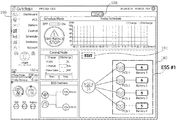
- FIG. 2 is a schematic diagram showing an interface displayed on a display by a display unit 190 .
- the interface may additionally include various menus for managing the power of the grid unit.
- the interface may be provided with a display window displaying the grid units contained in a specific group managed by the management unit 150 .
- FIG. 2 shows that a group ESS # 1 including four grid units as a specific group may be selected through a selection menu connected to the selection unit 130 .
- the display window may be replaced with an edit window capable of grouping a plurality of grid units.
- a maximum number of grid units may be displayed in the edit window.
- the user may select and group some of the maximum number of grid units.
- the editing unit 110 may assign a name of the new group such as ESS # 5 .
- the interface unit may be provided with a selection menu that selects each group by selecting a group name.
- the group displayed in the display window may be changed easily through the selection menu.
- a ESS battery-PCS-PMS structure
- a popular ESS battery-PCS structure
- the management unit 150 managing each grid unit may be configured with a micro PMS that may operate with low computing power at an embedded level.
- the management unit 150 may manage each grid unit included in the group selected by the selection menu and displayed in the display window, meanwhile the management unit may not manage the remaining grid units.
- a management module for managing the power input and output of the grid unit using the identification information of the grid unit may be provided for each group.
- each management module may be formed by program, a plurality of management modules may be easily stored in a small storage unit 170 .
- FIG. 3 is a schematic diagram showing grouping performed by the editing unit 110 of the present invention.
- the first grid unit, the second grid unit, the third grid unit, and the fourth grid unit exist from the top to the bottom.
- the first grid unit and the second grid unit are grouped into one group ESS # 2
- the second grid unit and the third grid unit are grouped into one group ESS # 3 , through the editing unit 110 .
- the management unit 150 may be provided with the second management module for managing the group ESS # 2 and the third management module for managing the group ESS # 3 .
- a first management module managing the ESS # 1 may additionally be provided in the management unit 150 .
- the management unit 150 may extract, from the storage unit 170 , a management module for managing a specific group that is newly changed every time a specific group is changed by the selection unit 130 and operate the management module. According to this, the management unit 150 is a PMS that manages only a specific group at a certain point in time and excludes the remaining groups except the specific group.
- the management module managing the remaining groups may be a surplus management module that is not operated.
- the surplus management module may operate as a redundancy means of the PMS that manages only a specific group.
- the management unit 150 may set a management module that manages another group different from the specific group as a sub management module.
- the sub management module may monitor a primary management module that manages the specific group, instead of managing other groups.
- FIG. 3 illustrates a case where the second management module of the group ESS # 2 becomes a primary management module and the third management module of the group ESS # 3 becomes a sub management module.
- FIG. 4 is a schematic diagram showing redundancy performed by the management unit 150 of the present invention.
- the sub management module may manage the specific group instead of the primary management module when an error occurs in the primary management module.
- the primary management module may receive the management information periodically or in real time. Suddenly, when the sub management module replaces the primary management module, the sub management module cannot know at what point in time to mange the specific group. When the sub management module receives the management information, the sub management module may manage the specific group continuously from that point in time to receive the information.
- the sub management module may transmit a heart bit signal to the primary management module.
- the sub management module may manage the specific group using the final management information received from the primary management module when there is no response to the heart bit signal from the primary management module. Since the third management module corresponding to the sub management module corresponds to a surplus management module not selected by the selection unit 130 , the sub management module may not manage the ESS # 3 . Since the third management module has the ability to manage other groups, it is possible to manage a specific group. However, the identification information of the grid unit included in the third management module should be replaced with the identification information of the grid unit included in the specific group. Identification information of a grid unit included in the specific group may be provided through the editing unit 110 or included in the management information received from the second management module.
- a plurality of grid units arranged in different sites may be freely grouped and managed.
- the management unit 150 may serve as an EMS that is higher than the PMS.
- the management unit 150 may be faithful to the PMS's function to manage some grid units. Which function is used depends on the grouping determined by a user, whereby the user has the advantage of utilizing the management unit 150 in various manners.
- a plurality of groups may be managed through one management unit 150 .
- grouping can be obtained in a combination that enables an optimum power demand reduction according to power demand fluctuation information that changes from moment to moment and a request from a superior.
- the management unit 150 may support switching between groups while replacing entire program managing each group. Since the management module corresponding to the program that manages each group exists, it is possible to use the surplus management module for other purposes.
- the management unit 150 can be configured with small or inexpensive hardware because it is focused on the function of the PMS that manages only a specific group.
- the management module managing the remaining groups can maintain a standby state in which the remaining groups are not managed, and the redundancy of the management modules managing the specific group using the surplus resources can be realized.
Landscapes
- Engineering & Computer Science (AREA)
- Power Engineering (AREA)
- Charge And Discharge Circuits For Batteries Or The Like (AREA)
- Remote Monitoring And Control Of Power-Distribution Networks (AREA)
Abstract
Description
Claims (6)
Applications Claiming Priority (5)
| Application Number | Priority Date | Filing Date | Title |
|---|---|---|---|
| KR10-2016-0111319 | 2016-08-31 | ||
| KR1020160111319A KR20180024668A (en) | 2016-08-31 | 2016-08-31 | On-site type ess management apparatus |
| KR1020160114601A KR101772018B1 (en) | 2016-09-06 | 2016-09-06 | On-site type ess management apparatus |
| KR10-2016-0114601 | 2016-09-06 | ||
| PCT/KR2017/004018 WO2018043862A1 (en) | 2016-08-31 | 2017-04-13 | On-site ess management device |
Publications (2)
| Publication Number | Publication Date |
|---|---|
| US20190199095A1 US20190199095A1 (en) | 2019-06-27 |
| US10978875B2 true US10978875B2 (en) | 2021-04-13 |
Family
ID=61301337
Family Applications (1)
| Application Number | Title | Priority Date | Filing Date |
|---|---|---|---|
| US16/329,511 Active 2037-06-10 US10978875B2 (en) | 2016-08-31 | 2017-04-13 | On-site ESS management device |
Country Status (2)
| Country | Link |
|---|---|
| US (1) | US10978875B2 (en) |
| WO (1) | WO2018043862A1 (en) |
Families Citing this family (4)
| Publication number | Priority date | Publication date | Assignee | Title |
|---|---|---|---|---|
| PL3689091T3 (en) | 2018-08-09 | 2025-03-31 | Google Llc | Method and user equipment to resume a wireless connection |
| CN109713701B (en) * | 2019-02-01 | 2022-08-30 | 国网江苏省电力有限公司 | Battery energy storage network load interaction method, terminal, system and medium controlled in superposition |
| WO2021124691A1 (en) | 2019-12-20 | 2021-06-24 | 株式会社村田製作所 | High-frequency module and communication device |
| US12607677B2 (en) * | 2021-02-19 | 2026-04-21 | Lg Energy Solution, Ltd. | Battery analysis apparatus and method |
Citations (6)
| Publication number | Priority date | Publication date | Assignee | Title |
|---|---|---|---|---|
| JP2011101553A (en) | 2009-11-09 | 2011-05-19 | Shimizu Corp | Energy storage system |
| KR101262265B1 (en) | 2011-11-11 | 2013-05-08 | (주)인텍에프에이 | Electric energy storage charging system |
| US20140239913A1 (en) * | 2011-09-22 | 2014-08-28 | Nec Corporation | Battery control system, battery control device, battery control method and recording medium |
| KR101500304B1 (en) | 2011-12-26 | 2015-03-11 | 주식회사 케이티 | A control method of charging and discharging of energy storage and system for it |
| KR101504170B1 (en) | 2011-12-15 | 2015-03-23 | 주식회사 케이티 | Cluster Unit Control of Energy Storage System and method of energy distribution thereof |
| KR20160012108A (en) | 2013-03-15 | 2016-02-02 | 디자인 플럭스 테크놀로지스, 엘엘씨 | Method and apparatus for creating a dynamically reconfigurable energy storage device |
-
2017
- 2017-04-13 WO PCT/KR2017/004018 patent/WO2018043862A1/en not_active Ceased
- 2017-04-13 US US16/329,511 patent/US10978875B2/en active Active
Patent Citations (6)
| Publication number | Priority date | Publication date | Assignee | Title |
|---|---|---|---|---|
| JP2011101553A (en) | 2009-11-09 | 2011-05-19 | Shimizu Corp | Energy storage system |
| US20140239913A1 (en) * | 2011-09-22 | 2014-08-28 | Nec Corporation | Battery control system, battery control device, battery control method and recording medium |
| KR101262265B1 (en) | 2011-11-11 | 2013-05-08 | (주)인텍에프에이 | Electric energy storage charging system |
| KR101504170B1 (en) | 2011-12-15 | 2015-03-23 | 주식회사 케이티 | Cluster Unit Control of Energy Storage System and method of energy distribution thereof |
| KR101500304B1 (en) | 2011-12-26 | 2015-03-11 | 주식회사 케이티 | A control method of charging and discharging of energy storage and system for it |
| KR20160012108A (en) | 2013-03-15 | 2016-02-02 | 디자인 플럭스 테크놀로지스, 엘엘씨 | Method and apparatus for creating a dynamically reconfigurable energy storage device |
Non-Patent Citations (2)
| Title |
|---|
| International Search Report for PCT/KR2017/004018 dated Jul. 14, 2017. |
| Written Opinion of the International Searching Authority for PCT/KR2017/004018 dated Jul. 14, 2017. |
Also Published As
| Publication number | Publication date |
|---|---|
| US20190199095A1 (en) | 2019-06-27 |
| WO2018043862A1 (en) | 2018-03-08 |
Similar Documents
| Publication | Publication Date | Title |
|---|---|---|
| US10978875B2 (en) | On-site ESS management device | |
| US9915927B2 (en) | System and method for accommodating power and non-transitory computer-readable medium storing program | |
| US10103575B2 (en) | Power interchange management system and power interchange management method for maintaining a balance between power supply and demand | |
| US9664745B1 (en) | Computer implemented system and method and computer program product for using battery information to automatically charge a battery | |
| US20150229128A1 (en) | Method of managing electric power, power management device, and program | |
| US11906942B2 (en) | Power grid controller device and system | |
| KR101928280B1 (en) | Unified management system for ess, and management and power control method thereof | |
| CN108694083A (en) | A kind of data processing method and device of server | |
| WO2015115070A1 (en) | Communication terminal, rechargeable-battery management method, and rechargeable-battery management program | |
| KR20210073836A (en) | Energy resources integrated operating system | |
| KR102131416B1 (en) | Operation system and method for virtual power plant using battery of electric vehicle | |
| KR101983836B1 (en) | Energy management system based on virtual power plant platform and management method therefor | |
| KR101772018B1 (en) | On-site type ess management apparatus | |
| US10714940B2 (en) | Power storage control apparatus and power storage control method | |
| KR20230089338A (en) | Power management method performing power management apparatus managing energy storage system based on power conversion system for connection of different batteries and power management apparatus therefor | |
| KR101494848B1 (en) | Builing control type power balancing system between the energy storage systems | |
| US20250012859A1 (en) | Battery information management system and method | |
| KR102357402B1 (en) | System for management state of charge of energy storage device | |
| KR20250068551A (en) | Smart battery-based electric vehicle charging system with multiple input ports and multiple output ports | |
| KR20220096856A (en) | Data management system for collecting and storing monitoring data of power converter system and method thereof | |
| AU2019100709A4 (en) | Distributed Energy Control | |
| CN108551453A (en) | Status information of equipment adapting method and device | |
| KR20220120838A (en) | Vehicle and its control method | |
| US20260081286A1 (en) | Modular energy storage and delivery system | |
| US9912155B2 (en) | Controlling power from cable to load |
Legal Events
| Date | Code | Title | Description |
|---|---|---|---|
| FEPP | Fee payment procedure |
Free format text: ENTITY STATUS SET TO UNDISCOUNTED (ORIGINAL EVENT CODE: BIG.); ENTITY STATUS OF PATENT OWNER: SMALL ENTITY |
|
| FEPP | Fee payment procedure |
Free format text: ENTITY STATUS SET TO SMALL (ORIGINAL EVENT CODE: SMAL); ENTITY STATUS OF PATENT OWNER: SMALL ENTITY |
|
| STPP | Information on status: patent application and granting procedure in general |
Free format text: DOCKETED NEW CASE - READY FOR EXAMINATION |
|
| AS | Assignment |
Owner name: GRIDWIZ INC, KOREA, REPUBLIC OF Free format text: ASSIGNMENT OF ASSIGNORS INTEREST;ASSIGNORS:KIM, KU HWAN;RYU, JUNE WOO;KIM, HYUN WOONG;AND OTHERS;SIGNING DATES FROM 20191001 TO 20191003;REEL/FRAME:050751/0019 |
|
| STPP | Information on status: patent application and granting procedure in general |
Free format text: NON FINAL ACTION MAILED |
|
| STPP | Information on status: patent application and granting procedure in general |
Free format text: NOTICE OF ALLOWANCE MAILED -- APPLICATION RECEIVED IN OFFICE OF PUBLICATIONS |
|
| STPP | Information on status: patent application and granting procedure in general |
Free format text: PUBLICATIONS -- ISSUE FEE PAYMENT RECEIVED |
|
| STPP | Information on status: patent application and granting procedure in general |
Free format text: PUBLICATIONS -- ISSUE FEE PAYMENT VERIFIED |
|
| STCF | Information on status: patent grant |
Free format text: PATENTED CASE |
|
| MAFP | Maintenance fee payment |
Free format text: PAYMENT OF MAINTENANCE FEE, 4TH YR, SMALL ENTITY (ORIGINAL EVENT CODE: M2551); ENTITY STATUS OF PATENT OWNER: SMALL ENTITY Year of fee payment: 4 |