US10976774B2 - Electronic device, terminal device, and method for controlling electronic device - Google Patents
Electronic device, terminal device, and method for controlling electronic device Download PDFInfo
- Publication number
- US10976774B2 US10976774B2 US16/365,958 US201916365958A US10976774B2 US 10976774 B2 US10976774 B2 US 10976774B2 US 201916365958 A US201916365958 A US 201916365958A US 10976774 B2 US10976774 B2 US 10976774B2
- Authority
- US
- United States
- Prior art keywords
- sliding seat
- electronic device
- frame
- guiding
- sliding
- Prior art date
- Legal status (The legal status is an assumption and is not a legal conclusion. Google has not performed a legal analysis and makes no representation as to the accuracy of the status listed.)
- Expired - Fee Related
Links
Images


Classifications
-
- G—PHYSICS
- G06—COMPUTING OR CALCULATING; COUNTING
- G06F—ELECTRIC DIGITAL DATA PROCESSING
- G06F1/00—Details not covered by groups G06F3/00 - G06F13/00 and G06F21/00
- G06F1/16—Constructional details or arrangements
- G06F1/1613—Constructional details or arrangements for portable computers
- G06F1/1615—Constructional details or arrangements for portable computers with several enclosures having relative motions, each enclosure supporting at least one I/O or computing function
- G06F1/1624—Constructional details or arrangements for portable computers with several enclosures having relative motions, each enclosure supporting at least one I/O or computing function with sliding enclosures, e.g. sliding keyboard or display
-
- G—PHYSICS
- G06—COMPUTING OR CALCULATING; COUNTING
- G06F—ELECTRIC DIGITAL DATA PROCESSING
- G06F1/00—Details not covered by groups G06F3/00 - G06F13/00 and G06F21/00
- G06F1/16—Constructional details or arrangements
- G06F1/1613—Constructional details or arrangements for portable computers
- G06F1/1626—Constructional details or arrangements for portable computers with a single-body enclosure integrating a flat display, e.g. Personal Digital Assistants [PDAs]
-
- G—PHYSICS
- G06—COMPUTING OR CALCULATING; COUNTING
- G06F—ELECTRIC DIGITAL DATA PROCESSING
- G06F1/00—Details not covered by groups G06F3/00 - G06F13/00 and G06F21/00
- G06F1/16—Constructional details or arrangements
- G06F1/1613—Constructional details or arrangements for portable computers
- G06F1/1633—Constructional details or arrangements of portable computers not specific to the type of enclosures covered by groups G06F1/1615 - G06F1/1626
- G06F1/1637—Details related to the display arrangement, including those related to the mounting of the display in the housing
-
- G—PHYSICS
- G06—COMPUTING OR CALCULATING; COUNTING
- G06F—ELECTRIC DIGITAL DATA PROCESSING
- G06F1/00—Details not covered by groups G06F3/00 - G06F13/00 and G06F21/00
- G06F1/16—Constructional details or arrangements
- G06F1/1613—Constructional details or arrangements for portable computers
- G06F1/1633—Constructional details or arrangements of portable computers not specific to the type of enclosures covered by groups G06F1/1615 - G06F1/1626
- G06F1/1675—Miscellaneous details related to the relative movement between the different enclosures or enclosure parts
- G06F1/1683—Miscellaneous details related to the relative movement between the different enclosures or enclosure parts for the transmission of signal or power between the different housings, e.g. details of wired or wireless communication, passage of cabling
-
- G—PHYSICS
- G06—COMPUTING OR CALCULATING; COUNTING
- G06F—ELECTRIC DIGITAL DATA PROCESSING
- G06F1/00—Details not covered by groups G06F3/00 - G06F13/00 and G06F21/00
- G06F1/16—Constructional details or arrangements
- G06F1/1613—Constructional details or arrangements for portable computers
- G06F1/1633—Constructional details or arrangements of portable computers not specific to the type of enclosures covered by groups G06F1/1615 - G06F1/1626
- G06F1/1684—Constructional details or arrangements related to integrated I/O peripherals not covered by groups G06F1/1635 - G06F1/1675
- G06F1/1686—Constructional details or arrangements related to integrated I/O peripherals not covered by groups G06F1/1635 - G06F1/1675 the I/O peripheral being an integrated camera
-
- G—PHYSICS
- G06—COMPUTING OR CALCULATING; COUNTING
- G06F—ELECTRIC DIGITAL DATA PROCESSING
- G06F1/00—Details not covered by groups G06F3/00 - G06F13/00 and G06F21/00
- G06F1/16—Constructional details or arrangements
- G06F1/1613—Constructional details or arrangements for portable computers
- G06F1/1633—Constructional details or arrangements of portable computers not specific to the type of enclosures covered by groups G06F1/1615 - G06F1/1626
- G06F1/1684—Constructional details or arrangements related to integrated I/O peripherals not covered by groups G06F1/1635 - G06F1/1675
- G06F1/1698—Constructional details or arrangements related to integrated I/O peripherals not covered by groups G06F1/1635 - G06F1/1675 the I/O peripheral being a sending/receiving arrangement to establish a cordless communication link, e.g. radio or infrared link, integrated cellular phone
-
- H—ELECTRICITY
- H04—ELECTRIC COMMUNICATION TECHNIQUE
- H04M—TELEPHONIC COMMUNICATION
- H04M1/00—Substation equipment, e.g. for use by subscribers
- H04M1/02—Constructional features of telephone sets
- H04M1/0202—Portable telephone sets, e.g. cordless phones, mobile phones or bar type handsets
- H04M1/0206—Portable telephones comprising a plurality of mechanically joined movable body parts, e.g. hinged housings
- H04M1/0208—Portable telephones comprising a plurality of mechanically joined movable body parts, e.g. hinged housings characterized by the relative motions of the body parts
- H04M1/0235—Slidable or telescopic telephones, i.e. with a relative translation movement of the body parts; Telephones using a combination of translation and other relative motions of the body parts
- H04M1/0237—Sliding mechanism with one degree of freedom
-
- H—ELECTRICITY
- H04—ELECTRIC COMMUNICATION TECHNIQUE
- H04M—TELEPHONIC COMMUNICATION
- H04M1/00—Substation equipment, e.g. for use by subscribers
- H04M1/02—Constructional features of telephone sets
- H04M1/0202—Portable telephone sets, e.g. cordless phones, mobile phones or bar type handsets
- H04M1/0249—Details of the mechanical connection between the housing parts or relating to the method of assembly
-
- H—ELECTRICITY
- H04—ELECTRIC COMMUNICATION TECHNIQUE
- H04M—TELEPHONIC COMMUNICATION
- H04M1/00—Substation equipment, e.g. for use by subscribers
- H04M1/02—Constructional features of telephone sets
- H04M1/0202—Portable telephone sets, e.g. cordless phones, mobile phones or bar type handsets
- H04M1/026—Details of the structure or mounting of specific components
- H04M1/0264—Details of the structure or mounting of specific components for a camera module assembly
-
- H—ELECTRICITY
- H04—ELECTRIC COMMUNICATION TECHNIQUE
- H04M—TELEPHONIC COMMUNICATION
- H04M1/00—Substation equipment, e.g. for use by subscribers
- H04M1/02—Constructional features of telephone sets
- H04M1/0202—Portable telephone sets, e.g. cordless phones, mobile phones or bar type handsets
- H04M1/026—Details of the structure or mounting of specific components
- H04M1/0266—Details of the structure or mounting of specific components for a display module assembly
-
- H—ELECTRICITY
- H04—ELECTRIC COMMUNICATION TECHNIQUE
- H04M—TELEPHONIC COMMUNICATION
- H04M1/00—Substation equipment, e.g. for use by subscribers
- H04M1/02—Constructional features of telephone sets
- H04M1/0202—Portable telephone sets, e.g. cordless phones, mobile phones or bar type handsets
- H04M1/026—Details of the structure or mounting of specific components
- H04M1/0277—Details of the structure or mounting of specific components for a printed circuit board assembly
-
- H—ELECTRICITY
- H04—ELECTRIC COMMUNICATION TECHNIQUE
- H04M—TELEPHONIC COMMUNICATION
- H04M1/00—Substation equipment, e.g. for use by subscribers
- H04M1/02—Constructional features of telephone sets
- H04M1/03—Constructional features of telephone transmitters or receivers, e.g. telephone hand-sets
-
- H—ELECTRICITY
- H05—ELECTRIC TECHNIQUES NOT OTHERWISE PROVIDED FOR
- H05K—PRINTED CIRCUITS; CASINGS OR CONSTRUCTIONAL DETAILS OF ELECTRIC APPARATUS; MANUFACTURE OF ASSEMBLAGES OF ELECTRICAL COMPONENTS
- H05K1/00—Printed circuits
- H05K1/02—Details
- H05K1/0277—Bendability or stretchability details
- H05K1/028—Bending or folding regions of flexible printed circuits
Definitions
- This disclosure relates to the field of electronic apparatuses, and more particularly to an electronic device, a terminal device, and a method for controlling an electronic device.
- a screen-to-body ratio of an electronic apparatus is restricted by functional components.
- install and arrangement of a camera module, a receiver module, a flashlight, a sensor, and the like may restrict improvement of the screen-to-body ratio of the electronic apparatus.
- a high screen-to-body ratio of the electronic apparatus is usually achieved by decreasing sizes of the functional components, which can result in high cost.
- An electronic device with flexible arrangement, a terminal device, and a method for controlling an electronic device are provided in the present disclosure.
- an electronic device is provided.
- the electronic device includes a frame, a sliding seat, a guiding mechanism, a drive mechanism, and multiple functional components.
- the multiple functional components are accommodated in the sliding seat.
- the frame includes a pair of side walls which are oppositely disposed and a top wall of side walls.
- the top wall defines an accommodating groove, and the accommodating groove extends through the pair of side walls.
- the sliding seat is slidably connected with the frame in the accommodating groove via the drive mechanism, and the guiding mechanism is disposed between the sliding seat and the frame, whereby the sliding seat driven by the drive mechanism extends from or is accommodated in the accommodating groove along a guiding direction of the guiding mechanism.
- the sliding seat is provided with at least one functional portion, whereby the multiple functional components are able to transmit (or deliver) a signal.
- a terminal device is provided.
- the terminal device includes an electronic device and a display module.
- the electronic device includes a frame, a sliding seat, a guiding mechanism, a drive mechanism, and multiple functional components.
- the multiple functional components are accommodated in the sliding seat.
- the frame includes a pair of side walls which are oppositely disposed and a top wall which is connected between the pair of side walls.
- the top wall defines an accommodating groove, and the accommodating groove extends through the pair of side walls.
- the sliding seat is slidably connected with the frame in the accommodating groove via the drive mechanism, and the guiding mechanism is disposed between the sliding seat and the frame, whereby the sliding seat driven by the drive mechanism extends from or is accommodated in the accommodating groove along a guiding direction of the guiding mechanism.
- the sliding seat is provided with at least one functional portion, whereby the multiple functional components are able to transmit a signal through the at least one functional portion.
- the display module covers the frame and is disposed opposite the sliding seat.
- a method for controlling an electronic device is provided.
- the method is applicable to an electronic device.
- the electronic device includes a frame, a sliding seat, a guiding mechanism, a drive mechanism, and multiple functional components, and the multiple functional components are accommodated in the sliding seat.
- the frame includes a pair of side walls which are oppositely disposed and a top wall.
- the top wall defines an accommodating groove, and the accommodating groove extends through the pair of side walls.
- the sliding seat is slidably connected with the frame in the accommodating groove via the drive mechanism, and the guiding mechanism is disposed between the sliding seat and the frame, whereby the sliding seat driven by the drive mechanism extends from or is accommodated in the accommodating groove along a guiding direction of the guiding mechanism.
- the sliding seat is provided with at least one functional portion, whereby the multiple functional components are able to transmit a signal through the at least one functional portion.
- the method includes the following.
- the electronic device receives a preset signal, where the preset signal is an extension signal or a retraction signal.
- the preset signal is the extension signal
- the electronic device controls the drive mechanism to drive the sliding seat to extend from the accommodating groove along a guiding direction of the guiding mechanism according to the preset signal.
- the preset signal is the retraction signal
- the electronic device controls the drive mechanism to drive the sliding seat to retract into the accommodating groove along the guiding direction of the guiding mechanism according to the preset signal.
- FIG. 1 is a schematic diagram illustrating an electronic device in a retracting-state according to Implementation 1 of the present disclosure.
- FIG. 2 is a schematic diagram illustrating the electronic device of FIG. 1 in an extending-state.
- FIG. 3 is a schematic exploded view illustrating the electronic device illustrated in FIG. 2 .
- FIG. 4 is a schematic diagram illustrating a drive mechanism of the electronic device in the extending-state according to Implementation 1 of the present disclosure.
- FIG. 5 is a schematic diagram illustrating the electronic device of FIG. 4 in the retracting-state.
- FIG. 6 is a schematic diagram illustrating the drive mechanism of the electronic device illustrated in FIG. 4 .
- FIG. 7 a schematic diagram illustrating a buffer member further provided for the electronic device illustrated in FIG. 4 .
- FIG. 8 a schematic diagram illustrating another buffer member further provided for the electronic device illustrated in FIG. 4 .
- FIG. 9 is a schematic diagram illustrating another drive mechanism of an electronic device in an extending-state according to Implementation 2 of the present disclosure.
- FIG. 10 is a schematic diagram illustrating the electronic device of FIG. 9 in a retracting-state.
- FIG. 11 is a schematic diagram illustrating an arrangement of guiding rods of an electronic device in an extending-state according to Implementation 3 of the present disclosure.
- FIG. 12 is a schematic diagram illustrating a sliding seat according to an implementation of the present disclosure.
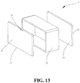
- FIG. 13 is a schematic diagram illustrating another sliding seat according to an implementation of the present disclosure.
- FIG. 14 is a schematic diagram illustrating an arrangement of functional components of a sliding seat of an electronic device in a retracting-state according to an implementation of the present disclosure.
- FIG. 15 is a schematic diagram illustrating the electronic device of FIG. 14 in an extending-state.
- FIG. 16 is a schematic diagram illustrating a terminal device according to an implementation of the disclosure.
- FIG. 17 is a schematic flowchart illustrating a method for controlling an electronic device according to an implementation of the present disclosure.
- the electronic device 100 can be any electronic apparatus.
- the electronic apparatus include smart apparatuses such as a tablet computer, a mobile phone, a camera, a personal computer (PC), a notebook computer, an in-vehicle apparatus, a wearable apparatus, or the like.
- directions of the electronic device 100 are defined with reference to a viewing angle illustrated in FIG. 1 : a width direction of the electronic device 100 is defined as X-direction, a length direction of the electronic device 100 is defined as Y-direction, and a thickness direction of electronic device 100 is defined as Z-direction.
- FIG. 1 is the electronic device 100 according to Implementation 1 of the present disclosure.
- the electronic device 100 mainly includes a frame 1 and a sliding seat 2 .
- the sliding seat 2 is slidably connected with the frame 1 to enable the electronic device 100 to make the sliding seat 2 extend from or retract into the frame 1 according to actual needs of a user.
- Multiple functional components 5 are accommodated in the sliding seat 2 .
- the sliding seat 2 can slide relative to the frame 1 to enable the multiple functional components 5 to slide out when the multiple functional components 5 are needed to work, thereby avoiding restriction on a screen-to-body ratio of a display screen of the electronic device 100 resulting from use of the multiple functional components 5 , which is beneficial to improving the screen-to-body ratio of the electronic device 100 .
- the electronic device 100 in the implementations of the disclosure includes the frame 1 , the sliding seat 2 , a guiding mechanism 4 , a drive mechanism 3 , and the multiple functional components 5 received in the sliding seat 2 .
- the frame 1 includes a pair of side walls 12 b which are oppositely disposed and a top wall 12 a which is connected between the pair of side walls 12 b .
- the top wall 12 a defines an accommodating groove 12 d .
- the accommodating groove 12 d extends through the pair of side walls 12 b .
- the sliding seat 2 is slidably connected with the frame 1 in the accommodating groove 12 d via the drive mechanism 3 .
- the guiding mechanism 4 is disposed on the sliding seat 2 , whereby the sliding seat 2 driven by the drive mechanism 3 extends from or is accommodated in the accommodating groove 12 d along a guiding direction of the guiding mechanism 4 .
- the sliding seat 2 is provided with at least one functional portion 5 a , through which the multiple functional components 5 are able to transmit a signal.
- the drive mechanism 3 can drive the sliding seat 2 to slide out of the frame 1 to make the functional portion 5 a extend from the frame 1 to transmit a signal(s), that is, there is no need to dispose the at least one functional portion 5 a corresponding to the multiple functional components 5 on the display screen of the electronic device 100 , which can improve the screen-to-body ratio of the electronic device 100 .
- the guiding mechanism 4 can make the sliding seat 2 keep sliding along a pre-determined path when the sliding seat 2 slides relative to the frame 1 , thereby ensuring accuracy and stability when the sliding seat 2 slides.
- the top wall 12 a of a side frame member 12 defines the accommodating groove 12 d , and in this way, the display screen (or a display module 7 ), the sliding seat 2 , and a middle plate 11 of the electronic device 100 form a sandwich structure when the sliding seat 2 is slidably connected with the frame 1 .
- Such a structure guarantees that the display screen and the middle plate 11 can protect the sliding seat 2 inside against crashing when the electronic device 100 drops or is collided by an external force.
- the frame 1 includes the middle plate 11 and the side frame member 12 surrounding the middle plate 11 .
- the side frame member 12 is configured to cover (understood as substantially cover and engage) the display screen to form a complete housing of the electronic device 100 .
- the middle plate 11 includes the pair of side walls 12 b which are oppositely disposed and the top wall 12 a and a bottom wall 12 c which are connected with the pair of side walls 12 b . That is to say, the middle plate 11 is substantially in a rectangular shape.
- the pair of side walls 12 b are also long sides of the electronic device 100 .
- the pair of side walls 12 b are configured to arrange a volume button, a card base, and the like of the electronic device 100 .
- the top wall 12 a and the bottom wall 12 c are short sides of the electronic device 100 .
- the bottom wall 12 c is configured to arrange an earpiece, a speaker, and the like of the electronic device 100 .
- Space inside the frame 1 except the accommodating groove 12 d is defined as an inner cavity of the frame 1 , that is, the accommodating groove 12 d and the inner cavity define a complete inner space of the frame 1 .
- a length of the accommodating groove 12 d along the X-direction is equal to a length of the frame 1 along the X-direction.
- part of the pair of side walls 12 b which is adjacent to the top wall 12 a , defines two openings due to existence of the accommodating groove 12 d , such that the sliding seat 2 corresponding to the accommodating groove 12 d has a larger volume to accommodate more functional components 5 .
- the number of functional components 5 of the sliding seat 2 increase, effect on the screen-to-body ratio of the display screen of the electronic device 100 will be reduced.
- the sliding seat 2 has a size corresponding to the accommodating groove 12 d , that is, the sliding seat fills in the whole accommodating groove 12 d .
- the sliding seat 2 has a first wall 2 a and a second wall 2 b which are arranged opposite to each other in Y-direction.
- the sliding seat 2 when the first wall 2 a of the sliding seat 2 extends from the top wall 12 a for a certain distance, the sliding seat 2 is completely extended from the frame 1 . That is to say, the sliding seat 2 is in an extending-state.
- FIG. 1 when the first wall 2 a of the sliding seat 2 is flush with the top wall 12 a , the sliding seat 2 is completely accommodated in the accommodating groove 12 d . That is to say, the sliding seat 2 is in a retracting-state.
- the sliding seat 2 can be moved out to make the sliding seat 2 be in the extending-state.
- one of the at least one functional portion 5 a of the sliding seat 2 is no longer occluded by the display screen.
- Said one of the multiple functional components 5 corresponding to said one of the at least one functional portion 5 a can transmit a signal to the outside.
- the multiple functional components 5 can include a front-facing camera component.
- a front-facing camera is a common feature of cameras, mobile phones, smartphones, and tablets.
- the functional portion 5 a corresponding to the front-facing camera component is a front-facing light-transmitting portion which can transmit light to the front-facing camera component.
- FIG. 2 when a front-facing camera function is needed to work, slide the sliding seat 2 to make the sliding seat 2 be in the extending-state, such that a camera function (such as taking pictures) of the front-facing camera component can be achieved via the front-facing light-transmitting portion.
- FIG. 1 when there is no need to use the front-facing camera, slide the sliding seat 2 to make the sliding seat 2 be in the retracting-state, which facilitates accommodation of the electronic device 100 .
- the at least one functional portion 5 a of the sliding seat 2 corresponds to different functional components 5 , and accordingly the at least one functional portion 5 a is able to transmit different signals.
- the functional portion 5 a corresponding to a camera assembly 51 is able to transmit light signals
- the functional portion 5 a corresponding to a receiver (i.e. voice receiver) 52 is able to transmit sound signals, and so on.
- the functional portion 5 a of the sliding seat 2 is mainly disposed on a first sliding surface 2 c and a second sliding surface 2 d which are disposed opposite to each other on the sliding seat 2 in the Z-direction.
- the arrangement of the functional portion 5 a on the sliding surfaces of the sliding seat 2 varies with the functional component 5 to which the functional portion 5 a corresponds.
- the drive mechanism 3 is fixed to the inner cavity of the frame 1 and connected with the sliding seat 2 , to drive the sliding seat 2 to slide relative to the frame 1 .
- the driving mechanism 3 includes a motor 31 , an active rod 32 , and a drive block 33 which are fixed in the frame 1 .
- the active rod 32 has one end fixedly connected to a rotating shaft 31 a of the motor 31 .
- the drive block 33 is in a driving connection with the active rod 32 and is connected with the sliding seat 2 , so that the drive block 33 drives the sliding seat 2 to slide when the motor 31 rotates.
- the driving manner of the drive mechanism 3 is to convert a rotational motion of the motor 31 into a rectilinear motion.
- the active rod 32 is a screw rod.
- the drive block 33 is block-shaped and has a threaded hole 33 a which matches the active rod 32 .
- the motor 31 rotates to drive the screw rod to slide relative to the drive block 33 connected with the sliding seat 2 , to achieve sliding of the sliding seat 2 .
- Driving of the drive mechanism 3 is steady, which guarantees that the sliding seat 2 of large volume can slide smoothly relative to the frame 1 .
- the motor 31 is fixedly disposed in the inner cavity of the frame 1 , and the motor 31 is vertically disposed in the frame 1 .
- the rotating shaft 31 a of the motor 31 is parallel to the Y-direction of the electronic device 100 , and such a disposing manner of the motor 31 guarantees that a size of the motor 31 in the X-direction is small, which facilitates arrangement of components of the electronic device 100 in the X-direction.
- the active rod 32 has one end fixedly connected with the rotating shaft 31 a of the motor 31 .
- the drive block 33 is sleeved on the active rod 32 . When the motor 31 rotates, the active rod 32 rotates accordingly.
- the drive block 33 since the drive block 33 is in threaded connection with the screw rod, the drive block 33 can move in the Y-direction of the electronic device 100 , thereby driving the sliding seat 2 connected with the drive block 33 to move in the Y-direction, to enable the sliding seat 2 to extend from or retract into the accommodating groove 12 d.
- Different rotation directions of the motor 31 result in different movement directions of the drive block 33 .
- the drive block 33 slides towards the top wall 12 a of the frame 1 to make the sliding seat 2 extend from the accommodating groove 12 d .
- the drive block 33 slides away from the top wall 12 a of the frame 1 to make the sliding seat 2 retract into the accommodating groove 12 d.
- the sliding seat 2 has a large volume and thus a large number of the functional components 5 can be received therein, which increases weight of the sliding seat 2 to some extent and further affect the stability and accuracy of sliding of the sliding seat 2 .
- generally no sliding seat 2 is provided due to failure to overcome such influence of the weight of the sliding seat 2 on the stability and accuracy of sliding.
- the guiding mechanism 4 is provided between the sliding seat 2 and the frame 1 . Such guiding mechanism 4 can effectively ensure the stability and accuracy when the sliding seat 2 of such a large volume slides.
- the guiding mechanism 4 can be configured as but not limited to the following.
- the electronic device 100 further includes a support plate 13 .
- the support plate 13 covers the frame 1 .
- the guiding mechanism 4 includes at least one sliding rail 41 and a guiding rod 42 .
- the at least one sliding rail 41 is disposed on the support plate 13 .
- the sliding seat 2 is slidably connected with the at least one sliding rail 41 .
- the guiding rod 42 has one end fixed in the frame 1 and the other end which can slide relative to the sliding seat 2 .
- the guiding rod 42 extends in a longitudinal direction parallel to a longitudinal direction of the sliding rail 41 .
- the guiding mechanism 4 is a combination of the sliding rail 41 and the guiding rod 42 .
- the sliding rail 41 can make the sliding seat 2 slide in a pre-determined direction, thereby ensuring accuracy of sliding of the sliding seat 2 .
- volume of the sliding seat 2 is large, the size of the sliding seat 2 in the X-direction is the same as the size of the frame 1 in the X-direction, the guiding rod 42 can support and guide the sliding seat 2 when the sliding seat 2 slides, and therefore, the sliding seat 2 can slide steadily and accurately relative to the frame 1 because of the guiding mechanism 4 , thereby further improving reliability of the electronic device 100 .
- the support plate 13 covers the side frame member 12 .
- the support plate 13 includes a first support surface 13 a and a second support surface 13 b which are oppositely disposed.
- the first support surface 13 a is configured to carry the display module 7 .
- the second support surface 13 b is configured to support the sliding seat 2 .
- the support plate 13 can be integrated with the side frame member 12 .
- the support plate 13 and the side frame member 12 can be detachable structures.
- the support plate 13 is fixed to the side frame member 12 via a screw, riveting, or the like. In this way, the accommodating groove 12 d is located between the support plate 13 and the middle plate 11 .
- the first sliding surface 2 c of the sliding seat 2 is attached to the support plate 13
- the second sliding surface 2 d of the sliding seat 2 is attached to the middle plate 11 .
- the support plate 13 is provided with two sliding rails 41 .
- One of the two sliding rails 41 is disposed close to one of the side walls 12 b of the frame 1
- the other one of the two sliding rails 41 is disposed close to the other one of the side walls 12 b of the frame 1 .
- sliding blocks corresponding to the sliding rails 41 are protruded and disposed on the sliding seat 2 to enable the sliding seat 2 to be slidably coupled with the sliding rails 41 via the sliding blocks.
- a cross section of the sliding rail 41 and a cross section of the sliding block form a dovetail shape.
- the guiding rod 42 is configured as follows.
- One guiding rod 42 is provided.
- the foregoing one guiding rod 42 is disposed adjacent to the drive mechanism 3 and has one end fixed to the drive mechanism 3 .
- the guiding rod 42 is disposed adjacent to the drive mechanism 3 . Since these two components are densely arranged, sizes of the drive mechanism 3 and the guiding rod 42 in the X-direction can be further reduced.
- the guiding rod 42 has one end fixed to the motor 31 and the other end slidably connected with the drive block 33 . That is to say, the one guiding rod 42 passes through the drive block 33 . As the drive block 33 slides correspondingly as the active rod 32 rotates, the drive block 33 also slides corresponding to the one guiding rod 42 .
- the guiding rod 42 can support the drive block 33 connected with the sliding seat 2 , thus preventing the sliding seat 2 from tilting due to uneven stress applied to the drive block 33 by the sliding seat 2 , and preventing the sliding seat 2 from tilting; tilting of the sliding seat 2 will result in lower stability and accuracy of sliding of the sliding seat 2 , which prevents the sliding seat 2 from moving out of the accommodating groove 12 d and retracting into the accommodating groove 12 d smoothly during sliding and thus causes the sliding seat 2 collide with a groove-wall of the accommodating groove 12 d . Therefore, the present scheme can improve reliability of the electronic device 100 .
- connection between the drive block 33 and the active rod 32 includes but is not limited to the following.
- the drive block 33 is fixedly connected with the active rod 32 .
- the drive block 33 is fixedly connected with the sliding seat 2 via a screw. As such, when the drive block 33 slides, the sliding seat 2 slides accordingly.
- the sliding seat 2 defines at least one connecting hole 2 e .
- the drive mechanism 3 further includes at least one connecting rod 34 .
- the at least one connecting rod 34 has one end fixed to the drive block 33 and the other end passing through the connecting hole 2 e of the sliding seat 2 .
- a central axis of the connecting rod 34 is perpendicular to the support plate 13 to make the sliding seat 2 slide relative to the connecting rod 34 .
- connection between the sliding seat 2 and the drive mechanism 3 makes degree of freedom of the sliding seat 2 and degree of freedom of the connecting rod 34 in the Z-direction of the electronic device 100 not restricted.
- the sliding seat 2 can conduct self-adaptive adjustment in the Z-direction during sliding to avoid a situation where the sliding seat 2 is unable to slide due to being stuck with the drive mechanism 3 , which improves reliability of the electronic device 100 .
- two connecting holes 2 e are provided.
- a central axis of the connecting hole 2 e is parallel to the Z-direction.
- two connecting rods 34 are provided.
- the connecting rod 34 is substantially a pin.
- the connecting rod 34 has one end fixed to the drive block 33 and the other end passing through the connecting hole 2 e , and the other end of the connecting rod 34 is unable to fall out of the connecting hole 2 e , which guarantees the connection relationship between the sliding seat 2 and the drive block 33 .
- part of the connecting rod 34 located in the connecting hole 2 e and the connecting hole 2 e are spaced apart, such that the sliding seat 2 can slide relative to the drive block 33 in the Z-direction, that is, degree of freedom of the sliding seat 2 and degree of freedom of the connecting rod 34 in the Z-direction of the electronic device 100 are not restricted, whereby the sliding seat 2 can be self-adaptive adjusted in the Z-direction during sliding, to avoid a situation where the sliding seat 2 is unable to slide due to being stuck with the drive mechanism 3 , which improves reliability of the electronic device 100 .
- the electronic device 100 switches to the extending-state from the retracting-state as follows.
- the motor 31 rotates, the screw rod rotates and drives the drive block 33 to slide towards the top wall 12 a of the frame 1 , thereby driving the sliding seat 2 to extend gradually from the accommodating groove 12 d until the electronic device 100 is in the extending-state.
- the sliding seat 2 can conduct self-adaptive adjustment in the Z-direction.
- the guiding mechanism 4 restricts the sliding seat 2 to a pre-determined direction.
- the electronic device 100 switches to the retracting-state from the extending-state as follows.
- the motor 31 rotates, the screw rod rotates and drives the drive block 33 to slide away from the top wall 12 a of the frame 1 , thereby driving the sliding seat 2 to retract gradually into the accommodating groove 12 d until the electronic device 100 is in the retracting-state.
- the sliding seat 2 can conduct self-adaptive adjustment in the Z-direction.
- the guiding mechanism 4 restricts the sliding seat 2 to a pre-determined direction.
- the electronic device 100 further includes a buffer member 5 .
- the buffer member 5 is located in the connecting hole 2 e and abuts against the connecting rod 34 and a hole-wall of the connecting hole 2 e .
- the buffer member 5 can absorb at least part of force transmitted to the drive mechanism 3 from the sliding seat 2 when the sliding seat 2 is subject to an external force.
- the buffer member 5 includes but is not limited to the following.
- the buffer member 5 is made of silica gel and is sleeved on part of the connecting rod 34 located in the connecting hole 2 e.
- the connecting hole 2 e includes a small hole and a big hole which are connected with each other and form substantially a gourd shape.
- the buffer member 5 is also substantially in a gourd shape which corresponds to shape of the connecting hole 2 e .
- the buffer member 5 is sleeved on a peripheral surface of the connecting rod 34 .
- the buffer member 5 can absorb part of the impact force applied to the sliding seat 2 though elastic deformation of the buffer member 5 itself. In this way, the external force transmitted to the drive block 33 decreases accordingly, thereby avoiding effectively damage on the drive mechanism 3 and ensuring that the drive mechanism 3 works reliably, which improves reliability of the electronic device 100 .
- the buffer member 5 is made of rubber which is sleeved on the connecting rod 34 , that is, the buffer member 5 wraps the connecting rod 34 , which is beneficial to absorbing force transmitted to the connecting rod 34 from all directions.
- the buffer member 5 thus structured is more effective.
- the buffer member 5 is a spring and an elastic force of the buffer member 5 is parallel to an extending direction of the sliding seat 2 .
- the connecting hole 2 e includes a small hole and a big hole which are connected with each other and form substantially a gourd shape.
- the connecting rod 34 is in the big hole.
- the spring is a compression spring.
- the spring has one end abutting against a hole-wall and the other end abutting against the connecting rod 34 .
- the elastic force of the spring is along the Y-direction.
- the spring can absorb part of the impact force applied to the sliding seat 2 though elastic deformation of the spring itself. In this way, the external force transmitted to the drive block 33 decreases accordingly, thereby avoiding effectively damage on the drive mechanism 3 and ensuring that the drive mechanism 3 works reliably, which improves reliability of the electronic device 100 .
- the multiple functional components 5 are disposed in the sliding seat 2 , and the sliding seat 2 can slide relative to the frame 1 .
- the drive mechanism 3 can drive the sliding seat 2 to slide out of the frame 1 to make the functional portion 5 a extend from the frame 1 to transmit a signal, that is, there is no need to dispose the at least one functional portion 5 a corresponding to the multiple functional components 5 on the display screen of the electronic device 100 , which is beneficial to improving the screen-to-body ratio of the electronic device 100 .
- the guiding mechanism 4 can make the sliding seat 2 keep sliding on a pre-determined path when the sliding seat 2 slides relative to the frame 1 , thereby ensuring accuracy and stability of sliding of the sliding seat 2 .
- an electronic device 200 according to Implementation 2 of the disclosure has a structure similar to that of the electronic device 100 according to Implementation 1 of the disclosure.
- the electronic device 200 differs from the electronic device 100 in that, the drive mechanism 63 includes a motor 631 , a gear 632 , a rack 634 , and a drive block 633 which are fixed on the support plate 13 .
- the gear 632 is sleeved on a rotating shaft 631 a of the motor 631 , the rack 634 is engaged with the gear 632 , and the rack 634 is slidable in the longitudinal direction of the sliding rail 41 , that is, the rack 634 can slide along the Y-direction.
- the drive block 633 is disposed between the rack 634 and the sliding seat 2 , so that the drive block 633 can drive the sliding seat 2 to slide when the rack 634 slides, and the one guiding rod 42 has one end fixed to the motor 631 and the other end slidably connected with the drive block 633 .
- the driving manner of the drive mechanism 63 is to convert a rotational motion of the motor 631 into a rectilinear motion.
- the drive block 633 is fixedly connected with the rack 634 .
- the motor 631 rotates, it drives the gear 632 to rotate, and the gear 632 further drives the rack 634 engaged with the gear 632 to slide, thereby driving the drive block 633 connected with the sliding seat 2 to slide to achieve sliding of the sliding seat 2 .
- Driving of the drive mechanism 63 is steady, which guarantees that the sliding seat 2 of large volume can slide smoothly relative to the frame 1 .
- the motor 631 is fixedly disposed in the inner cavity of the frame 1 , and the motor 631 is disposed horizontally in the frame 1 .
- the rotating shaft 631 a of the motor 631 is parallel to the Z-direction of the electronic device 200 , and such a disposing manner of the motor 631 guarantees that the motor 631 has a small size in the X-direction, which facilitates arrangement of components of the electronic device 200 in the X-direction.
- the motor 631 is fixed to the second support surface 13 b of the support plate 13 .
- the gear 632 is sleeved on the rotating shaft 631 a of the motor 631 .
- the support plate 13 further has a sliding groove.
- Part of the rack 634 is located in the sliding groove, which guarantees that the rack 634 can slide along the direction of the sliding groove with sliding of the gear 632 after the rack 634 is engaged with the gear 632 .
- a longitudinal direction of the sliding groove is along the Y-direction.
- the drive block 633 is fixed to the rack 634 . When the rack 634 slides, the drive block 633 slides accordingly.
- the motor 631 rotates, it drives the gear 632 to rotate.
- the rack 634 to which the drive block 633 is fixed is able to move along the Y-direction of the electronic device 200 , thereby driving the sliding seat 2 to move in the Y-direction and thus enabling the sliding seat 2 to extend from or retract into the accommodating groove 12 d.
- Different rotation directions of the motor 631 result in different movement directions of the drive block 633 .
- the drive block 633 slides towards the top wall 12 a of the frame 1 to make the sliding seat 2 extend from the accommodating groove 12 d .
- the drive block 633 slides away from the top wall 12 a of the frame 1 to make the sliding seat 2 retract into the accommodating groove 12 d.
- the guiding mechanism 4 of the electronic device 200 according to Implementation 2 has a same structure as the guiding mechanism 4 of the electronic device 100 according to Implementation 1.
- the difference mainly lies in changes of a structure of the drive mechanism 63 and changes of connection between some components of the guiding mechanism 4 and some components of the drive mechanism 63 , which will be described in detail hereinafter.
- the guiding rod 42 has one end fixed to the second support surface 13 b of the support plate 13 .
- the guiding rod 42 and the rack 634 are separated with a space therebetween.
- the one guiding rod 42 has the other end slidably connected with the drive block 633 .
- the guiding rod 42 can support the drive block 633 connected with the siding seat 2 , preventing the sliding seat 2 from tilting due to uneven stress applied to the drive block 633 by the sliding seat 2 , and preventing the sliding seat 2 from tilting; tilting of the sliding seat 2 will result in lower stability and accuracy of sliding of the sliding seat 2 , which prevents the sliding seat 2 from moving out of the accommodating groove 12 d and retracting into the accommodating groove 12 d smoothly during sliding and thus causes the sliding seat 2 to collide with a groove-wall of the accommodating groove 12 d . Therefore, the present scheme can improve reliability of the electronic device 200 .
- the electronic device 200 switches to the extending-state from the retracting-state as follows.
- the gear 632 rotates and drives the drive block 633 to slide towards the top wall 12 a of the frame 1 , thereby driving the sliding seat 2 to extend gradually from the accommodating groove 12 d until the electronic device 200 is in the extending-state.
- the sliding seat 2 can conduct self-adaptive adjustment.
- the guiding mechanism 4 restricts the sliding seat 2 to a pre-determined direction.
- the electronic device 200 switches to the retracting-state from the extending-state as follows.
- the gear 632 rotates and drives the drive block 633 to slide away from the top wall 12 a of the frame 1 , thereby driving the sliding seat 2 retract gradually into the accommodating groove 12 d until the electronic device 200 is in the retracting-state.
- the sliding seat 2 can conduct self-adaptive adjustment.
- the guiding mechanism 4 restricts the sliding seat 2 to a pre-determined direction.
- the guiding rod 42 includes two guiding rods, that is, two guiding rods 42 are provided. Each of the two guiding rods 42 has one end fixed to the support plate 13 and the other end slidably connected with the sliding seat 2 .
- the drive mechanism 3 is located between the two guiding rods 42 .
- the guiding rod 42 includes two guiding rods. One of the two guiding rods 42 is located on one side of the drive mechanism 3 and the other one of the two guiding rods 42 is located on the other side of the drive mechanism 3 to guide and support the sliding seat 2 , which guarantees that the sliding seat 2 , which has a large volume and is guided and supported by the two guiding rods 42 , is able to slide steadily and reliably relative to the frame 1 .
- the sliding seat 2 is provided with two positioning structures.
- the positioning structure can be a groove or a protrusion to enable the other side of each of the two guiding rods 42 to pass through the groove or the protrusion to be connected with the sliding seat 2 .
- the sliding seat 2 slides, the sliding seat 2 slides along the sliding rails 41 of the support plate 13 , and at the same time, the two guiding rods 42 guarantee that the sliding seat 2 of large volume provided herein can be further supported and guided, thereby further improving stability and accuracy of sliding of the sliding seat 2 .
- the guiding mechanism 4 can also be applicable to the electronic device 200 according to Implementation 2 of the disclosure, which will not be repeated herein.
- a structure of the sliding seat 2 according to Implementation 1, Implementation 2, and Implementation 3 of the disclosure includes but is not limited to the following.
- the sliding seat 2 has a body 21 and at least one light-transmitting plate 22 .
- the body 21 defines at least one functional hole 21 a .
- One of the at least one light-transmitting plate 22 is disposed in one of the at least one functional hole 21 a to form one of the at least one functional portion 5 a.
- the sliding seat 2 thus structured is partially provided with the functional portion 5 a (such as the light-transmitting plate 22 or a hole), which results in low cost.
- the functional portion 5 a such as the light-transmitting plate 22 or a hole
- most part of the sliding seat 2 is made of metal and is therefore of high strength.
- the sliding seat 2 includes a sliding frame 23 and two sliding plates 24 .
- the sliding frame 23 is made of a conductive material.
- One sliding plate 24 covers one side of the sliding frame 23 and the other sliding plate 24 covers the other side of the sliding frame 23 to define an inner cavity of the sliding seat 2 to accommodate the multiple functional components 5 .
- the two sliding plates 24 are made of a light-transmitting material to form the at least one functional portion 5 a.
- the first sliding surface 2 c and the second sliding surface 2 d of the sliding seat 2 are both made of glass. Since the first sliding surface 2 c and the second sliding surface 2 d are both made of glass, the first sliding surface 2 c and the second sliding surface 2 d can function as a light-transmitting functional portion 5 a .
- the camera assembly 51 or a light sensor of the sliding seat 2 is needed to work, as long as the sliding seat 2 is moved out of the accommodating groove 12 d , light from outside can be transmitted through the first sliding surface 2 c or the second sliding surface 2 d , thereby ensuring that the camera assembly 51 or the light sensor can work reliably.
- a first receiving hole D 1 is defined in a position corresponding to a receiver 52 on the sliding seat 2 to achieve transmission of the sound signal.
- the sliding seat 2 of such structure has two surfaces made of glass, which facilitates light transmission of the multiple functional components 5 of the sliding seat 2 without providing the at least one functional portion 5 a in corresponding positions.
- a structure of the multiple functional components 5 according to Implementation 1, Implementation 2, and Implementation 3 of the disclosure can be configured as but not limited to the following.
- the electronic device 100 further includes a display module 7 .
- the display module 7 covers the frame 1 and is disposed opposite the sliding seat 2 .
- the display module 7 covers the side frame member 12 to form a complete housing of the electronic device 100 and is carried on the first support surface 13 a of the support plate 13 .
- the display module 7 can be configured to display an electronic signal, and can be configured to receive an electronic signal input by touch.
- the display module 7 is a touch display screen.
- the multiple functional components 5 are accommodated in the sliding seat 2 , when the sliding seat 2 slide relative to the frame 1 , the multiple functional components 5 can move out when they are needed to work, thereby avoiding restriction of use of the multiple functional components 5 on the screen-to-body ratio of the display screen of the electronic device 100 , which is beneficial to improving the screen-to-body ratio of the electronic device 100 .
- the structure of the multiple functional components 5 according to Implementation 1, Implementation 2, and Implementation 3 of the disclosure includes but is not limited to the following.
- the electronic device 100 further includes a mainboard 8 .
- the mainboard 8 is carried on the support plate 13 and has a receiving portion 8 a .
- the drive mechanism 3 is located in the receiving portion 8 a.
- the mainboard 8 is carried on the second support surface 13 b of the support plate 13 .
- Part of the mainboard 8 adjacent to the second wall 2 b of the sliding seat 2 is hollowed out to define the receiving portion 8 a .
- the receiving portion 8 a is configured to receive the drive mechanism 3 or the drive mechanism 63 . That is to say, the drive mechanism 3 or the drive mechanism 63 is directly fixed to the support plate 13 rather than disposed on the mainboard 8 , which decreases the size of the electronic device 100 in the Z-direction.
- the structure of the multiple functional components 5 according to Implementation 1, Implementation 2, and Implementation 3 of the disclosure includes but is not limited to the following.
- the electronic device 100 further includes a flexible electrical connector 9 .
- the flexible electrical connector 9 has one end located in the sliding seat 2 and electrically connected with the multiple functional components 5 .
- the flexible electrical connector 9 has the other end extending from the sliding seat 2 to be electrically connected with the mainboard 8 of the frame 1 .
- the multiple functional components 5 of the sliding seat 2 are electrically connected with the mainboard 8 of the frame 1 via the flexible electrical connector 9 , as such, when the sliding seat 2 slides, electrical signals of the multiple functional components 5 will not be interrupted and the multiple functional components 5 can still work normally, thereby further improving reliability of the electronic device 100 .
- the flexible electrical connector 9 is a winding flexible circuit board. When the sliding seat 2 slides, the flexible electrical connector 9 extends or winds. In other implementations, the flexible electrical connector 9 can be a cable.
- the flexible electrical connector 9 is embodied as a winding flexible circuit board to make the flexible electrical connector 9 deform with different states of the sliding seat 2 , that is, when the flexible electrical connector 9 winds, the flexible electrical connector 9 occupies only a small area.
- the flexible electrical connector 9 when the sliding seat 2 is in an extending-state, the flexible electrical connector 9 is extended to the longest. Referring to FIG. 14 , when the sliding seat 2 is in a retracting-state, the flexible electrical connector 9 winds in a roll and thus occupies less space of the electronic device 100 .
- the multiple functional components 5 further includes a camera assembly 51 and a receiver 52 , and both the camera assembly 51 and the receiver 52 are electrically connected with one end of the flexible electrical connector 9 .
- the camera assembly 51 and the receiver 52 are disposed side by side.
- the camera assembly 51 is mainly located in the middle of the sliding seat 2 .
- the receiver 52 is disposed adjacent to the first wall 2 a of the sliding seat 2 , to achieve sound signal output of the receiver 52 when the first wall 2 a of the sliding seat 2 is exposed from the top wall 12 a.
- the flexible electrical connector 9 and the camera assembly 51 are disposed side by side in the Y-direction of the electronic device 100 .
- the flexible electrical connector 9 includes two flexible electrical connectors which are arranged along the X-direction of the electronic device 100 .
- the two flexible electrical connectors 9 are disposed adjacent to the second wall 2 b of the sliding seat 2 , which enables the two flexible electrical connectors 9 to extend from the sliding seat 2 to be electrically connected with a circuit board of the electronic device 100 , thus further optimizing internal space of the electronic device 100 .
- the camera assembly 51 and the receiver 52 are both electrically connected with the two flexible electrical connectors 9 , thereby optimizing arrangement of flexible circuit boards inside the sliding seat 2 and saving space.
- the camera assembly 51 can include but is not limited to the following: at least one of a front-facing camera assembly, a rear camera assembly, and a flashlight.
- the multiple functional components 5 further include a radiating body 53 of an antenna, a secondary circuit board 54 , and a cable 55 .
- the radiating body 53 is disposed adjacent to an edge of the sliding seat 2 .
- the radiating body 53 is electrically coupled with one end of the cable 55 via the secondary circuit board 54 , to enable transmission and reception of signals.
- the cable 55 has the other end extending from the sliding seat 2 to be electrically connected with the mainboard 8 of the frame 1 .
- the radiating body 53 is a part of the antenna, and, besides the radiating body 53 , the antenna further includes circuits disposed on the mainboard.
- the radiating body 53 is electrically coupled with the mainboard 8 via the cable 55 rather than via the flexible electrical connector 9 , to prevent an electrical signal of the radiating body 53 from being interrupted by other functional components 5 , thereby further enhancing radiation of the radiating body 53 .
- the radiating body 53 is disposed adjacent to the first wall 2 a of the sliding seat 2 , which decreases probability of occlusion by user's hand when the radiating body 53 radiates signals, thereby ensuring that the radiating body 53 has better radiation performance.
- a structure of the cable 55 makes the cable 55 seldom wind or be extended when the sliding seat 2 slides, thereby ensuring transmission of electrical signals between the radiating body 53 and the mainboard 8 .
- the secondary circuit board 54 includes two said secondary circuit boards, and the cable 55 accordingly includes two said cables.
- One of the two secondary circuit boards 54 is located on one side of the camera assembly 51
- the other one of the two secondary circuit boards 54 is located on the other one side of the camera assembly 51 .
- One of the two secondary circuit boards 54 is provided with a matching circuit electrically connected with the radiating body 53 .
- the cables 55 are electrically connected between the two secondary circuit boards 54 and the mainboard 8 .
- the radiating body 53 is disposed in the sliding seat 2 .
- the sliding seat 2 is in the extending-state, since the radiating body 53 is not occluded by the display screen or a back plate, the radiating body 53 has better radiation performance. Therefore, by sliding the sliding seat 2 out of the accommodating groove 12 d , stronger signals can be obtained, if necessary.
- a sound signal of the receiver 52 is output includes but is not limited to the following.
- the sliding seat 2 defines a first receiving hole D 1 .
- the receiver 52 has a vibration portion 52 a communicating with the first receiving hole D 1 on the sliding seat 2 , whereby a sound signal of the receiver 52 is output through the first receiving hole D 1 after the receiver 52 extends from the accommodating groove 12 d.
- the first receiving hole D 1 is defined adjacent to the first wall 2 a .
- the vibration portion 52 a of the receiver 52 is sealed and connected with the first receiving hole D 1 and vibrates to generate a sound signal.
- the sound signal is transmitted to the outside through the first receiving hole D 1 .
- the sound signal of the receiver 52 can be transmitted to the outside through the first receiving hole D 1 .
- the sliding seat 2 defines a first receiving hole D 1
- the receiver 52 has a vibration portion 52 a communicating with the first receiving hole D 1 , whereby a sound signal of the receiver 52 is output through the first receiving hole D 1 after the receiver 52 extends from the accommodating groove 12 d .
- the frame 1 defines a second receiving hole D 2 .
- the second receiving hole D 2 communicates with the first receiving hole D 1 , whereby a sound signal of the receiver 52 is output to the second receiving hole D 2 through the first receiving hole D 1 when the receiver 52 is accommodated in the accommodating groove 12 d.
- the first receiving hole D 1 is defined adjacent to the first wall 2 a .
- the vibration portion 52 a of the receiver 52 is sealingly connected with the first receiving hole D 1 and vibrates to generate a sound signal.
- the sound signal is transmitted to the outside through the first receiving hole D 1 .
- the second receiving hole D 2 is defined on the top wall 12 a to avoid influence on the screen-to-body ratio of the display screen.
- the second receiving hole D 2 communicates with the first receiving hole D 1 . In this way, when the sliding seat 2 is accommodated in the accommodating groove 12 d , the sound signal of the receiver 52 can be transmitted to the second receiving hole D 2 through the first receiving hole D 1 to realize sound signal output of the receiver 52 .
- the multiple functional components 5 can further include but not limited to at least one of a speaker, a microphone, and an infrared sensor.
- the electronic device 100 provided herein can make the sliding seat 2 extend from or retract into the frame 1 according to users' actual needs as follows.
- the sliding seat 2 can slide to the extending-state accordingly.
- one of the at least one functional portion 5 a on the sliding seat 2 is no longer occluded by the display screen.
- Said one of the multiple functional components 5 corresponding to said one of the at least one functional portion 5 a is able to transmit a signal to the outside.
- the multiple functional components 5 are disposed in the sliding seat 2 , and the sliding seat 2 can slide relative to the frame 1 .
- the drive mechanism 3 can drive the sliding seat 2 to slide out of the frame 1 to make the at least one functional portion 5 a extend from the frame 1 to transmit a signal, that is, there is no need to dispose the at least one functional portion 5 a corresponding to the multiple functional components 5 on the display screen of the electronic device 100 , which is beneficial to improving the screen-to-body ratio of the electronic device 100 .
- the guiding mechanism 4 can make the sliding seat 2 keep sliding along a pre-determined path when the sliding seat 2 slides relative to the frame 1 , thereby ensuring accuracy and stability of sliding of the sliding seat 2 .
- FIG. 16 is a schematic diagram illustrating a terminal device 400 according to an implementation of the disclosure.
- the terminal device 400 includes the electronic device described above and a display module 401 .
- the display module 401 covers the frame 1 and is disposed opposite the sliding seat 2 .
- FIG. 17 is a schematic flowchart illustrating a method for controlling an electronic device according to an implementation of the present disclosure.
- the method can be applicable to but is not limited to the electronic device of Implementation 1, the electronic device of Implementation 2, and the electronic device of Implementation 3 described above.
- the method includes the following.
- the electronic device receives a preset signal.
- the preset signal is an extension signal or a retraction signal.
- the extension signal is configured to indicate a sliding seat to extend from an accommodating groove.
- the retraction signal is configured to indicate the sliding seat to retract into the accommodating groove.
- the electronic device controls a drive mechanism according to the preset signal.
- the electronic device controls the drive mechanism according to the preset signal as follows.
- the preset signal is the extension signal
- the electronic device controls, according to the preset signal, the drive mechanism to drive the sliding seat to extend from the accommodating groove along a guiding direction of a guiding mechanism.
- the preset signal is the retraction signal
- the electronic device controls, according to the preset signal, the drive mechanism to drive the sliding seat to retract into the accommodating groove along the guiding direction of the guiding mechanism.
- the extension signal or the retraction signal received by the electronic device can be input through voice, text, touch, etc. by a user. After the electronic device receives the extension signal, the electronic device will be in an extending-state.
- the method is applicable to the above electronic device which is beneficial to improving the screen-to-body ratio of the electronic device.
- the guiding mechanism is able to make the sliding seat keep sliding along a pre-determined path when the sliding set slides relative to the frame, thereby ensuring accuracy and stability during sliding of the sliding seat.
Landscapes
- Engineering & Computer Science (AREA)
- Theoretical Computer Science (AREA)
- Computer Hardware Design (AREA)
- Physics & Mathematics (AREA)
- General Engineering & Computer Science (AREA)
- Signal Processing (AREA)
- General Physics & Mathematics (AREA)
- Human Computer Interaction (AREA)
- Mathematical Physics (AREA)
- Computer Networks & Wireless Communication (AREA)
- Microelectronics & Electronic Packaging (AREA)
- Seats For Vehicles (AREA)
- Chair Legs, Seat Parts, And Backrests (AREA)
- Telephone Set Structure (AREA)
Abstract
Description
Claims (13)
Applications Claiming Priority (2)
| Application Number | Priority Date | Filing Date | Title |
|---|---|---|---|
| CN201810282608.6 | 2018-03-31 | ||
| CN201810282608.6A CN110324447B (en) | 2018-03-31 | 2018-03-31 | Electronic device and control method of electronic device |
Publications (2)
| Publication Number | Publication Date |
|---|---|
| US20190302841A1 US20190302841A1 (en) | 2019-10-03 |
| US10976774B2 true US10976774B2 (en) | 2021-04-13 |
Family
ID=66048997
Family Applications (1)
| Application Number | Title | Priority Date | Filing Date |
|---|---|---|---|
| US16/365,958 Expired - Fee Related US10976774B2 (en) | 2018-03-31 | 2019-03-27 | Electronic device, terminal device, and method for controlling electronic device |
Country Status (5)
| Country | Link |
|---|---|
| US (1) | US10976774B2 (en) |
| EP (1) | EP3547656B1 (en) |
| CN (1) | CN110324447B (en) |
| ES (1) | ES2870904T3 (en) |
| WO (1) | WO2019184875A1 (en) |
Cited By (3)
| Publication number | Priority date | Publication date | Assignee | Title |
|---|---|---|---|---|
| US11221650B2 (en) * | 2018-03-31 | 2022-01-11 | Shenzhen Heytap Technology Corp., Ltd. | Electronic device, terminal device, and method for controlling electronic device |
| US20220053075A1 (en) * | 2019-05-22 | 2022-02-17 | Samsung Electronics Co., Ltd. | Electronic device including camera pop-up structure |
| US12517557B2 (en) * | 2022-01-18 | 2026-01-06 | Honor Device Co., Ltd. | Synchronization mechanism, rotating shaft mechanism, and electronic device |
Families Citing this family (21)
| Publication number | Priority date | Publication date | Assignee | Title |
|---|---|---|---|---|
| JP1629382S (en) * | 2018-02-05 | 2019-04-15 | ||
| USD879733S1 (en) * | 2018-03-16 | 2020-03-31 | Guangdong Oppo Mobile Telecommunications Corp., Ltd. | Mobile phone |
| USD908671S1 (en) * | 2018-11-16 | 2021-01-26 | Samsung Electronics Co., Ltd. | Electronic device |
| USD908104S1 (en) * | 2018-11-16 | 2021-01-19 | Samsung Electronics Co., Ltd. | Electronic device |
| CN111262974A (en) * | 2018-12-03 | 2020-06-09 | 深圳富泰宏精密工业有限公司 | Electronic device |
| KR102648987B1 (en) * | 2019-04-09 | 2024-03-19 | 삼성전자 주식회사 | Electronic device including rotatable camera |
| CN111866224A (en) * | 2019-04-26 | 2020-10-30 | 北京小米移动软件有限公司 | Electronic equipment |
| KR102775303B1 (en) * | 2019-05-09 | 2025-03-05 | 삼성전자주식회사 | Electronic device incluidng slide body |
| CN110753141A (en) * | 2019-10-16 | 2020-02-04 | 捷开通讯(深圳)有限公司 | terminal with adjustable screen size |
| CN110995303B (en) * | 2019-11-18 | 2021-08-17 | 维沃移动通信有限公司 | Wearable device, control method thereof, and computer-readable storage medium |
| CN110969961A (en) * | 2019-12-11 | 2020-04-07 | 深圳彩晨科技有限公司 | Super clear high brightness anticollision type LED commercial display screen |
| CN111416897B (en) * | 2020-03-30 | 2021-04-23 | 维沃移动通信有限公司 | Electronic equipment |
| CN111541804A (en) * | 2020-05-08 | 2020-08-14 | 维沃移动通信有限公司 | Electronic equipment, control method and control device |
| EP4187351A4 (en) * | 2020-10-12 | 2024-01-24 | Samsung Electronics Co., Ltd. | ELECTRONIC DEVICE WITH FLEXIBLE DISPLAY |
| US12261972B2 (en) | 2020-10-16 | 2025-03-25 | Lg Electronics Inc. | Flexible display device |
| CN113141744B (en) * | 2021-04-22 | 2022-12-27 | 维沃移动通信有限公司 | Electronic device |
| CN115412622B (en) * | 2021-05-28 | 2026-03-20 | 北京小米移动软件有限公司 | Opening mechanism and electronic equipment |
| CN113433363B (en) * | 2021-06-24 | 2023-08-01 | 广东电网有限责任公司 | Connecting device |
| CN115529366A (en) * | 2021-06-25 | 2022-12-27 | 北京小米移动软件有限公司 | Slide rail mechanism, flexible screen structure and electronic equipment |
| CN113286470B (en) * | 2021-06-25 | 2022-05-31 | 四川农业大学 | Natural language recognition processing device and use method thereof |
| CN113805651A (en) * | 2021-08-10 | 2021-12-17 | 荣耀终端有限公司 | Keyboard support and electronic equipment |
Citations (28)
| Publication number | Priority date | Publication date | Assignee | Title |
|---|---|---|---|---|
| US20030064688A1 (en) * | 2001-10-03 | 2003-04-03 | Nec Corporation | Slide-type portable communication apparatus |
| EP1528758A1 (en) | 2003-11-01 | 2005-05-04 | Samsung Electronics Co., Ltd. | Synchronized sliding module for a splitted keyboard of a mobile terminal and a method of using it. |
| US20070273786A1 (en) * | 2006-05-26 | 2007-11-29 | Samsung Electronics Co., Ltd. | Portable electronic device and camera |
| CN101355756A (en) | 2004-07-21 | 2009-01-28 | 三星电子株式会社 | Method for controlling camera mode in portable terminal |
| US20090323292A1 (en) | 2008-06-25 | 2009-12-31 | Hwang Yong-Jin | Mobile terminal |
| US20100124955A1 (en) * | 2008-11-17 | 2010-05-20 | Chi Mei Communication Systems, Inc. | Sliding-type portable terminal |
| CN102138113A (en) | 2008-08-29 | 2011-07-27 | 诺基亚公司 | Device with auto-slide keypad |
| CN203251333U (en) | 2013-04-15 | 2013-10-23 | 天津华锐源科技有限公司 | Mobile phone |
| CN204031223U (en) | 2014-04-21 | 2014-12-17 | 张晗月 | The full frame smart mobile phone of a kind of movable receiver photoflash lamp camera |
| CN105208149A (en) | 2015-08-31 | 2015-12-30 | 小米科技有限责任公司 | Mobile terminal display structure and mobile terminal |
| CN105453526A (en) | 2014-07-23 | 2016-03-30 | 华为技术有限公司 | a terminal device |
| CN105554196A (en) | 2016-01-26 | 2016-05-04 | 孔岳 | Full-screen mobile phone |
| CN105630079A (en) | 2014-11-04 | 2016-06-01 | 张永昌 | Integrated computer device |
| CN205320124U (en) | 2016-01-26 | 2016-06-15 | 孔岳 | Full screen mobile phone |
| CN105842959A (en) | 2016-05-13 | 2016-08-10 | 北京小米移动软件有限公司 | Telescopic camera |
| CN106094990A (en) | 2016-06-12 | 2016-11-09 | 张帆 | The screen maximized electronic equipment of accounting and using method thereof |
| CN106657456A (en) | 2016-10-24 | 2017-05-10 | 珠海格力电器股份有限公司 | Mobile terminal |
| CN106713549A (en) | 2017-01-09 | 2017-05-24 | 广东欧珀移动通信有限公司 | Electronic device |
| CN106790801A (en) | 2016-12-15 | 2017-05-31 | 卢春宁 | One kind has the telescopic mobile communication equipment of modularization |
| CN106856516A (en) | 2015-12-09 | 2017-06-16 | 小米科技有限责任公司 | Electronic equipment |
| CN206413083U (en) | 2017-01-24 | 2017-08-15 | 北京小米移动软件有限公司 | Electronic equipment |
| CN107071242A (en) | 2017-01-24 | 2017-08-18 | 北京小米移动软件有限公司 | Electronic equipment |
| CN107197133A (en) | 2017-07-21 | 2017-09-22 | 维沃移动通信有限公司 | A kind of mobile terminal and CCD camera assembly |
| CN107370843A (en) | 2016-05-13 | 2017-11-21 | 中兴通讯股份有限公司 | Motion control method for mobile terminal and receiver thereof |
| EP3255867A1 (en) | 2015-07-13 | 2017-12-13 | Guangdong Oppo Mobile Telecommunications Corp., Ltd | Flexible screen mobile terminal with two bendable ends |
| CN206960841U (en) | 2017-06-14 | 2018-02-02 | 山东祈锦光电科技有限公司 | A kind of Portable mobile phone projecting apparatus |
| CN107800828A (en) | 2017-11-16 | 2018-03-13 | 珠海市魅族科技有限公司 | Terminal device and its control method and computer-readable recording medium and device |
| CN207926660U (en) | 2018-02-09 | 2018-09-28 | 广东欧珀移动通信有限公司 | Mobile terminal |
-
2018
- 2018-03-31 CN CN201810282608.6A patent/CN110324447B/en not_active Expired - Fee Related
-
2019
- 2019-03-25 WO PCT/CN2019/079534 patent/WO2019184875A1/en not_active Ceased
- 2019-03-27 EP EP19165502.6A patent/EP3547656B1/en not_active Not-in-force
- 2019-03-27 ES ES19165502T patent/ES2870904T3/en active Active
- 2019-03-27 US US16/365,958 patent/US10976774B2/en not_active Expired - Fee Related
Patent Citations (29)
| Publication number | Priority date | Publication date | Assignee | Title |
|---|---|---|---|---|
| US20030064688A1 (en) * | 2001-10-03 | 2003-04-03 | Nec Corporation | Slide-type portable communication apparatus |
| EP1528758A1 (en) | 2003-11-01 | 2005-05-04 | Samsung Electronics Co., Ltd. | Synchronized sliding module for a splitted keyboard of a mobile terminal and a method of using it. |
| CN101355756B (en) | 2004-07-21 | 2012-10-10 | 三星电子株式会社 | Method for controlling a camera mode in a portable terminal |
| CN101355756A (en) | 2004-07-21 | 2009-01-28 | 三星电子株式会社 | Method for controlling camera mode in portable terminal |
| US20070273786A1 (en) * | 2006-05-26 | 2007-11-29 | Samsung Electronics Co., Ltd. | Portable electronic device and camera |
| US20090323292A1 (en) | 2008-06-25 | 2009-12-31 | Hwang Yong-Jin | Mobile terminal |
| CN102138113A (en) | 2008-08-29 | 2011-07-27 | 诺基亚公司 | Device with auto-slide keypad |
| US20100124955A1 (en) * | 2008-11-17 | 2010-05-20 | Chi Mei Communication Systems, Inc. | Sliding-type portable terminal |
| CN203251333U (en) | 2013-04-15 | 2013-10-23 | 天津华锐源科技有限公司 | Mobile phone |
| CN204031223U (en) | 2014-04-21 | 2014-12-17 | 张晗月 | The full frame smart mobile phone of a kind of movable receiver photoflash lamp camera |
| CN105453526A (en) | 2014-07-23 | 2016-03-30 | 华为技术有限公司 | a terminal device |
| CN105630079A (en) | 2014-11-04 | 2016-06-01 | 张永昌 | Integrated computer device |
| EP3255867A1 (en) | 2015-07-13 | 2017-12-13 | Guangdong Oppo Mobile Telecommunications Corp., Ltd | Flexible screen mobile terminal with two bendable ends |
| CN105208149A (en) | 2015-08-31 | 2015-12-30 | 小米科技有限责任公司 | Mobile terminal display structure and mobile terminal |
| CN106856516A (en) | 2015-12-09 | 2017-06-16 | 小米科技有限责任公司 | Electronic equipment |
| CN205320124U (en) | 2016-01-26 | 2016-06-15 | 孔岳 | Full screen mobile phone |
| CN105554196A (en) | 2016-01-26 | 2016-05-04 | 孔岳 | Full-screen mobile phone |
| CN107370843A (en) | 2016-05-13 | 2017-11-21 | 中兴通讯股份有限公司 | Motion control method for mobile terminal and receiver thereof |
| CN105842959A (en) | 2016-05-13 | 2016-08-10 | 北京小米移动软件有限公司 | Telescopic camera |
| CN106094990A (en) | 2016-06-12 | 2016-11-09 | 张帆 | The screen maximized electronic equipment of accounting and using method thereof |
| CN106657456A (en) | 2016-10-24 | 2017-05-10 | 珠海格力电器股份有限公司 | Mobile terminal |
| CN106790801A (en) | 2016-12-15 | 2017-05-31 | 卢春宁 | One kind has the telescopic mobile communication equipment of modularization |
| CN106713549A (en) | 2017-01-09 | 2017-05-24 | 广东欧珀移动通信有限公司 | Electronic device |
| CN107071242A (en) | 2017-01-24 | 2017-08-18 | 北京小米移动软件有限公司 | Electronic equipment |
| CN206413083U (en) | 2017-01-24 | 2017-08-15 | 北京小米移动软件有限公司 | Electronic equipment |
| CN206960841U (en) | 2017-06-14 | 2018-02-02 | 山东祈锦光电科技有限公司 | A kind of Portable mobile phone projecting apparatus |
| CN107197133A (en) | 2017-07-21 | 2017-09-22 | 维沃移动通信有限公司 | A kind of mobile terminal and CCD camera assembly |
| CN107800828A (en) | 2017-11-16 | 2018-03-13 | 珠海市魅族科技有限公司 | Terminal device and its control method and computer-readable recording medium and device |
| CN207926660U (en) | 2018-02-09 | 2018-09-28 | 广东欧珀移动通信有限公司 | Mobile terminal |
Non-Patent Citations (5)
| Title |
|---|
| Communication pursuant to Article 94(3) EPC issued in corresponding European application No. 19165502.6 dated Jul. 20, 2020. |
| English translation of First office action issued in corresponding CN application No. 201810282608.6 dated Jun. 19, 2020. |
| Extended European search report issued in corresponding European application No. 19165502.6 dated May 24, 2019. |
| International search report issued in corresponding international application No. PCT/CN2019/079534 dated Jun. 26, 2019. |
| OA2 with English Translation issued in corresponding CN application No. 201810282608.6 dated Jan. 5, 2021. |
Cited By (4)
| Publication number | Priority date | Publication date | Assignee | Title |
|---|---|---|---|---|
| US11221650B2 (en) * | 2018-03-31 | 2022-01-11 | Shenzhen Heytap Technology Corp., Ltd. | Electronic device, terminal device, and method for controlling electronic device |
| US20220053075A1 (en) * | 2019-05-22 | 2022-02-17 | Samsung Electronics Co., Ltd. | Electronic device including camera pop-up structure |
| US11799996B2 (en) * | 2019-05-22 | 2023-10-24 | Samsung Electronics Co., Ltd. | Electronic device including camera pop-up structure |
| US12517557B2 (en) * | 2022-01-18 | 2026-01-06 | Honor Device Co., Ltd. | Synchronization mechanism, rotating shaft mechanism, and electronic device |
Also Published As
| Publication number | Publication date |
|---|---|
| EP3547656A1 (en) | 2019-10-02 |
| WO2019184875A1 (en) | 2019-10-03 |
| US20190302841A1 (en) | 2019-10-03 |
| EP3547656B1 (en) | 2021-03-24 |
| CN110324447B (en) | 2021-05-28 |
| CN110324447A (en) | 2019-10-11 |
| ES2870904T3 (en) | 2021-10-28 |
Similar Documents
| Publication | Publication Date | Title |
|---|---|---|
| US10976774B2 (en) | Electronic device, terminal device, and method for controlling electronic device | |
| US11221650B2 (en) | Electronic device, terminal device, and method for controlling electronic device | |
| US10516814B2 (en) | Camera assembly and electronic device | |
| CN100367063C (en) | Lens driving device, camera assembly and portable electronic equipment | |
| WO2020168862A1 (en) | Terminal device | |
| US10084948B2 (en) | Portable electronic device having mechanism to move embedded camera module to different positions | |
| EP3866448B1 (en) | Mobile terminal | |
| CN108513055B (en) | Electronic components and electronic devices | |
| WO2019227974A1 (en) | Electronic assembly and electronic device | |
| CN110278361B (en) | Mobile terminal | |
| CN110417957A (en) | Functional component, electronic device, and control method of electronic device | |
| CN209201113U (en) | Mobile terminal | |
| CN110324056B (en) | Electronic device and control method of electronic device | |
| WO2019228050A1 (en) | Imaging component, electronic component, electronic apparatus, and control method for electronic apparatus | |
| CN110320969A (en) | Electronic device | |
| CN109962998A (en) | Functional component, electronic device and control method thereof | |
| CN110320968B (en) | Electronic device and control method of electronic device | |
| CN108418919A (en) | Electronic device and control method thereof | |
| CN209201114U (en) | Mobile terminal | |
| HK40012105B (en) | Electronic device and control method of electronic device | |
| HK40012105A (en) | Electronic device and control method of electronic device | |
| EP4436195A1 (en) | Camera module and electronic device | |
| CN110320967A (en) | Slide assemblies and electronic device | |
| CN121967577A (en) | An electronic device | |
| CN112153248A (en) | Electronic equipment |
Legal Events
| Date | Code | Title | Description |
|---|---|---|---|
| AS | Assignment |
Owner name: GUANGDONG OPPO MOBILE TELECOMMUNICATIONS CORP., LT Free format text: ASSIGNMENT OF ASSIGNORS INTEREST;ASSIGNORS:SUN, ZHIGANG;ZENG, ZANJIAN;ZHOU, GUOAN;AND OTHERS;REEL/FRAME:048713/0585 Effective date: 20190103 Owner name: GUANGDONG OPPO MOBILE TELECOMMUNICATIONS CORP., LTD., CHINA Free format text: ASSIGNMENT OF ASSIGNORS INTEREST;ASSIGNORS:SUN, ZHIGANG;ZENG, ZANJIAN;ZHOU, GUOAN;AND OTHERS;REEL/FRAME:048713/0585 Effective date: 20190103 |
|
| FEPP | Fee payment procedure |
Free format text: ENTITY STATUS SET TO UNDISCOUNTED (ORIGINAL EVENT CODE: BIG.); ENTITY STATUS OF PATENT OWNER: LARGE ENTITY |
|
| STPP | Information on status: patent application and granting procedure in general |
Free format text: NON FINAL ACTION MAILED |
|
| STPP | Information on status: patent application and granting procedure in general |
Free format text: NOTICE OF ALLOWANCE MAILED -- APPLICATION RECEIVED IN OFFICE OF PUBLICATIONS |
|
| STPP | Information on status: patent application and granting procedure in general |
Free format text: RESPONSE TO NON-FINAL OFFICE ACTION ENTERED AND FORWARDED TO EXAMINER |
|
| STPP | Information on status: patent application and granting procedure in general |
Free format text: NOTICE OF ALLOWANCE MAILED -- APPLICATION RECEIVED IN OFFICE OF PUBLICATIONS |
|
| STPP | Information on status: patent application and granting procedure in general |
Free format text: AWAITING TC RESP, ISSUE FEE PAYMENT VERIFIED |
|
| STPP | Information on status: patent application and granting procedure in general |
Free format text: PUBLICATIONS -- ISSUE FEE PAYMENT VERIFIED |
|
| STCF | Information on status: patent grant |
Free format text: PATENTED CASE |
|
| FEPP | Fee payment procedure |
Free format text: MAINTENANCE FEE REMINDER MAILED (ORIGINAL EVENT CODE: REM.); ENTITY STATUS OF PATENT OWNER: LARGE ENTITY |
|
| LAPS | Lapse for failure to pay maintenance fees |
Free format text: PATENT EXPIRED FOR FAILURE TO PAY MAINTENANCE FEES (ORIGINAL EVENT CODE: EXP.); ENTITY STATUS OF PATENT OWNER: LARGE ENTITY |
|
| STCH | Information on status: patent discontinuation |
Free format text: PATENT EXPIRED DUE TO NONPAYMENT OF MAINTENANCE FEES UNDER 37 CFR 1.362 |
|
| FP | Lapsed due to failure to pay maintenance fee |
Effective date: 20250413 |