US10974804B2 - Maintenance unit for an inboard marine engine - Google Patents
Maintenance unit for an inboard marine engine Download PDFInfo
- Publication number
- US10974804B2 US10974804B2 US15/318,548 US201515318548A US10974804B2 US 10974804 B2 US10974804 B2 US 10974804B2 US 201515318548 A US201515318548 A US 201515318548A US 10974804 B2 US10974804 B2 US 10974804B2
- Authority
- US
- United States
- Prior art keywords
- conduit
- fluid
- vessel
- chamber
- service unit
- Prior art date
- Legal status (The legal status is an assumption and is not a legal conclusion. Google has not performed a legal analysis and makes no representation as to the accuracy of the status listed.)
- Active, expires
Links
- 238000012423 maintenance Methods 0.000 title description 5
- 239000012530 fluid Substances 0.000 claims abstract description 97
- 238000004891 communication Methods 0.000 claims abstract description 12
- XLYOFNOQVPJJNP-UHFFFAOYSA-N water Substances O XLYOFNOQVPJJNP-UHFFFAOYSA-N 0.000 claims description 71
- 230000037452 priming Effects 0.000 claims description 38
- 238000009428 plumbing Methods 0.000 description 5
- 230000002528 anti-freeze Effects 0.000 description 4
- 238000001816 cooling Methods 0.000 description 4
- 238000010276 construction Methods 0.000 description 2
- 239000002826 coolant Substances 0.000 description 2
- 230000001419 dependent effect Effects 0.000 description 2
- 230000005484 gravity Effects 0.000 description 2
- 230000001105 regulatory effect Effects 0.000 description 2
- 239000012809 cooling fluid Substances 0.000 description 1
- 230000008878 coupling Effects 0.000 description 1
- 238000010168 coupling process Methods 0.000 description 1
- 238000005859 coupling reaction Methods 0.000 description 1
- 239000000463 material Substances 0.000 description 1
- 238000000034 method Methods 0.000 description 1
- 238000007789 sealing Methods 0.000 description 1
- 125000000391 vinyl group Chemical group [H]C([*])=C([H])[H] 0.000 description 1
- 229920002554 vinyl polymer Polymers 0.000 description 1
Images


Classifications
-
- B—PERFORMING OPERATIONS; TRANSPORTING
- B63—SHIPS OR OTHER WATERBORNE VESSELS; RELATED EQUIPMENT
- B63H—MARINE PROPULSION OR STEERING
- B63H21/00—Use of propulsion power plant or units on vessels
- B63H21/38—Apparatus or methods specially adapted for use on marine vessels, for handling power plant or unit liquids, e.g. lubricants, coolants, fuels or the like
-
- B—PERFORMING OPERATIONS; TRANSPORTING
- B63—SHIPS OR OTHER WATERBORNE VESSELS; RELATED EQUIPMENT
- B63B—SHIPS OR OTHER WATERBORNE VESSELS; EQUIPMENT FOR SHIPPING
- B63B17/00—Vessels parts, details, or accessories, not otherwise provided for
- B63B17/0027—Tanks for fuel or the like ; Accessories therefor, e.g. tank filler caps
-
- F—MECHANICAL ENGINEERING; LIGHTING; HEATING; WEAPONS; BLASTING
- F16—ENGINEERING ELEMENTS AND UNITS; GENERAL MEASURES FOR PRODUCING AND MAINTAINING EFFECTIVE FUNCTIONING OF MACHINES OR INSTALLATIONS; THERMAL INSULATION IN GENERAL
- F16K—VALVES; TAPS; COCKS; ACTUATING-FLOATS; DEVICES FOR VENTING OR AERATING
- F16K21/00—Fluid-delivery valves, e.g. self-closing valves
- F16K21/04—Self-closing valves, i.e. closing automatically after operation
- F16K21/18—Self-closing valves, i.e. closing automatically after operation closed when a rising liquid reaches a predetermined level
-
- F—MECHANICAL ENGINEERING; LIGHTING; HEATING; WEAPONS; BLASTING
- F16—ENGINEERING ELEMENTS AND UNITS; GENERAL MEASURES FOR PRODUCING AND MAINTAINING EFFECTIVE FUNCTIONING OF MACHINES OR INSTALLATIONS; THERMAL INSULATION IN GENERAL
- F16K—VALVES; TAPS; COCKS; ACTUATING-FLOATS; DEVICES FOR VENTING OR AERATING
- F16K31/00—Actuating devices; Operating means; Releasing devices
- F16K31/12—Actuating devices; Operating means; Releasing devices actuated by fluid
- F16K31/18—Actuating devices; Operating means; Releasing devices actuated by fluid actuated by a float
Definitions
- the present invention relates to inboard marine engines.
- the invention relates to a service or maintenance unit for an inboard marine engine to preventing flooding of the engine.
- FIG. 1 is a schematic of an inboard marine engine.
- FIG. 2 is a schematic of a service unit according to one embodiment of the invention.
- FIGS. 3 and 4 are perspective views of the service unit of FIG. 2 .
- FIG. 5 is a perspective view of an exemplary inboard marine engine
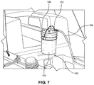
- FIGS. 6 and 7 are perspective views of the service unit of FIGS. 3 and 4 coupled to the engine of FIG. 5 .
- FIG. 8 is a detailed perspective view of FIG. 6 .
- FIGS. 9 and 10 are schematics of service units according to additional embodiments of the invention.
- FIG. 1 illustrates a boat 10 (e.g., sailboat) including an inboard marine engine systems 12 .
- Many types of inboard marine engine systems are often positioned in a hull 16 of the boat 10 and therefore, are positioned below the water line 20 .
- the exemplary inboard marine engine system 12 like most inboard marine engine systems, uses water from the ocean or lake as coolant.
- water is drawn in through an inlet 22 via a first or pickup water hose 24 by a pump 28 .
- the water passes through the pump 28 to a second hose 32 , which guides the water to a heat exchanger 36 and through an engine 40 to cool the interior of the engine 40 .
- the engine 40 may be either diesel or gasoline.
- the water then passes through a manifold mixer 44 where it mixes with exhaust.
- the water/exhaust combination then moves through a lift muffler 48 that helps to move the water from the manifold mixer 44 upwards to an outlet 52 in the boat 10 via a fourth hose 56 .
- the engine 40 is positioned below the water line 20 , the water that is drawn in through the inlet 22 must move upwards against gravity through the engine 40 on route to the outlet 52 .
- water In order to prevent the water from moving backwards and into the engine 40 , water must move through the system at a rate that is specific to the pump or the engine type. This rate is readily achievable when the boat is in water because the water source (e.g., the ocean or lake) is unpressurized. As such, the pump 28 dictates the intake of water through the inlet.
- a sailboat generally includes an engine system that includes a 1 ⁇ 2 inch pump to a 3 ⁇ 4 inch pump, which means that the inlet and outlet diameters of the in-feed and out-feed tubing running to and from the engine, respectively, measure approximately 1 ⁇ 2 inch to 3 ⁇ 4 inch.
- engine systems having pumps with alternative constructions and specifications may be employed.
- the engine system and pump system may be suitable for any type of boat other than a sailboat.
- the rate of fluid through the engine system is specific to the type of engine system and pump. Therefore, each pump may move water through the system at different rates or a variety of rates. The rate of fluid through the system is dependent on several factors of the engine system.
- the type of engine, the horsepower of the system, the pressure of the water, and the diameter of the in-feed/out-feed tubes are only a few of the factors that ensure that the rate of water through the system is appropriate.
- the types of pumps and relevant factors given above are merely exemplary and other engine types and configurations having other types of pumps may move water at rates that are dependent on a variety of other factors than those discussed above.
- the boat 10 does not have access to unpressurized water.
- the engine 40 often needs to be run while the boat 10 is out of water (i.e., dry docked).
- FIGS. 2-4 illustrate a service or maintenance unit 100 that provides an unpressurized fluid source for running inboard engines 12 that are positioned at or below the water line 20 .
- the service unit 100 includes a sealed container or vessel 104 that defines a chamber 108 that is configured to receive unpressured fluid such as water or antifreeze, for example.
- a first or inlet conduit 112 is coupled to the vessel 104 and is configured to guide the fluid from an inlet 116 to the chamber 108 .
- the inlet 116 is configured to matingly receive a hose.
- a valve 120 is coupled to the inlet conduit 112 .
- the valve 120 is positioned at a first end 124 of the vessel 104 within the chamber 108 and is configured to selectively allow fluid to pass therethrough.
- the valve 120 is a Hudson-type valve that includes a float 128 and a control diaphragm chamber 132 .
- the valve 120 will allow fluid to flow therethrough until a predetermined amount of fluid is received within the chamber 108 such that the fluid reaches a bottom of the valve 120 (e.g., a height H above the bottom 148 of the vessel 304 ).
- the valve 120 may include other valve types.
- the illustrated service unit 100 is a vessel 104 that can receive up to six gallons of fluid therein.
- the predetermined amount of fluid is approximately 5 gallons, which is the amount of fluid that the vessel 104 can accommodate before the fluid level contacts a bottom of the valve 120 .
- the vessel 104 may be any be configured to receive more or less fluid and the predetermined fluid amount may be greater or less than what is discussed above.
- the vessel 104 may be able to receive 2-10 gallons of fluid with a predetermined fluid level of approximately 1.75 gallons to 9.75 gallons.
- the valve 120 is responsive to fluid pressures in the range of 12-65 psi. Further, in additional or alternative embodiments, the valve 120 may have a different configuration.
- the inlet conduit 112 includes a first or inlet control flow valve 136 that is configured to determine a flow rate of fluid that passes from the inlet 116 to the valve 120 .
- a second or outlet conduit 140 is coupled to the first end 124 of the vessel 104 .
- An extension member 144 is coupled to a first end of the outlet conduit 140 and extends from substantially the first end 124 of the vessel 104 substantially to a second, opposite end 148 of the vessel 104 .
- a hose 146 may extend from a second end of the outlet conduit 140 .
- the outlet conduit 140 includes a second or outlet flow control valve 154 that is configured to determine a flow rate of fluid that passes from the vessel 104 through to the outlet conduit 140 . In the embodiment illustrated FIGS.
- each of the flow control valves 136 , 154 is a ball valve, for example, and includes an actuator 136 ′, 154 ′ that is adjustable to determine how much fluid is able to flow therethrough.
- the flow control valves 136 , 154 may be other suitable types of valves.
- the flow control valves 136 , 154 of FIGS. 2-4 are the same type of valve, however, in other embodiments, they may be different types of valves.
- the first flow valve 333 is a ball valve and the second flow control valve 354 is a Venturi-type valve, which will be discussed in greater detail below.
- the service unit 100 is assembled by providing and sealing the vessel 104 .
- the inlet conduit 112 is coupled to the vessel 104 such that it is in fluid communication with chamber 108 .
- the outlet conduit 140 is also coupled to the vessel 104 such that it is in fluid communication with the chamber 108 .
- a fluid passageway 160 is therefore defined from the inlet 116 through the inlet conduit 112 , the chamber 108 , and the outlet conduit 140 .
- the method includes coupling the valve 120 to the inlet conduit 112 within the chamber 108 such that the valve 120 is configured to prevent the fluid from entering the chamber 108 when the predetermined amount of fluid is reached within the chamber 108 .
- the first flow control valve 136 which selectively determines the flow rate through the inlet conduit 112
- the second flow control valve 154 which selectively determines the flow rate through the outlet conduit 140 , are both coupled to the service unit 100 .
- the service unit 100 is configured to be coupled to the pump 28 of the engine 40 to deliver unpressurized fluid to the engine 40 .
- water from a pressurized water source 166 i.e., a hose
- the engine 40 Prior to use ( FIG. 5 ), the engine 40 is turned off and the pickup hose 24 is uncoupled from the pump 28 .
- the outlet conduit 140 is coupled to the pump 28 of the engine 40 to replace the pickup hose 24 .
- the inlet conduit 112 is coupled to the pressurized water source 166 ( FIG. 7 ).
- the vessel 104 fills with water at a rate in the range of between 5-10 gallons/minute at a pressure in the range of 45-60 psi when the first flow control valve 136 is open and the second flow control valve 154 is closed.
- the vessel may fill at a rate of 7.5 gallons/minute at a pressure of 50 psi.
- the second flow control valve 154 is opened. When both the first flow control valve 140 and the second flow control valve 154 are open (or at least partially open), water passes from the vessel 104 to the outlet conduit 140 to the engine 40 , while water continues to enter the vessel 104 through the inlet conduit 112 .
- water contained within the vessel 104 is taken up by the extension member 144 and the second conduit 140 at a rate that is determined by the type of the pump 28 , as described above, such that water moves through the engine 40 normally as described above.
- the flow rate of water to the vessel 104 can be regulated by adjusting the first flow control valve 136 .
- the first flow control valve 136 can also be closed or partially closed to either close off the inlet conduit 112 entirely or regulate the flow of water therethrough.
- the flow rate to the engine 40 can be regulated by adjusting the second flow control valve 154 .
- Adjusting the flow control valve 154 also allows the user to regulate a temperature of the engine as well as a rate of cooling of the same. If the engine 40 is stopped or the second flow control valve 136 is closed water will continue to be delivered to the vessel 104 until the height of the water reaches the bottom of the valve 120 (i.e., the predetermined amount of fluid is reached) at which point the valve 120 will close. In other words, the water will no longer be able to enter the vessel 104 once the height of the water reaches the bottom of the valve 120 . In this way, if water is not exiting the vessel 104 through the outlet conduit 140 , the vessel 104 will not overflow.
- FIG. 9 illustrates a service unit 300 according to another embodiment of the invention.
- the service unit 300 of FIG. 9 is similar to the service unit 100 of FIGS. 2-4 ; therefore, like structure will be identified by like reference numerals plus “200” and only the differences will be discussed hereafter.
- the service unit 300 includes an opening 370 in a side wall 374 of the vessel 304 that is sealed with a plug or bushing 378 having an orifice 382 .
- the plug 378 is threadingly coupled to the wall 374 of the vessel 304 , although in other embodiments, the plug 378 may be coupled to the wall 374 in any suitable way.
- the plug 378 is positioned within the wall 374 such that the orifice 382 is positioned at distance D below the maximum height H that water can reach within the vessel 304 .
- the distance D is approximately 1.0 inches, although in other embodiments the distance may be greater or less than 1.0 inch.
- the distance D may measure approximately 0.5 inches to 2.0 inches.
- the plug is sealingly coupled to the outlet conduit 340 , which is coupled to the hose 346 .
- a tube or conduit 386 extends from the second end 348 of the vessel 304 through the orifice 382 in the plug 378 such that the tube 386 is in fluid communication with the outlet conduit 340 .
- the tube 386 has a diameter of approximately 0.25 inches, however, in other embodiments, the diameter may be between about 0.1 inches and 0.4 inches.
- the tube 386 is a priming feature used to the prime the pump 28 .
- the second flow control valve 154 is a Venturi-type control valve.
- the Venturi-type control valve allows small controlled amounts of water flow to reduce by approximately 5 to 10% per turn of valve actuator 354 ′. Accordingly, the second flow control valve 354 ensures an adjustable flow the pump 28 in gallons per minute.
- the second flow control valve 354 is an equalizer of water into vessel 304 versus water out of vessel 304 .
- the second flow control valve 354 also doubles as a plumbing siphon break. Having a Venturi-type control valve in to the outlet conduit 340 greatly reduces vacuum related squeezing of the hose 346 during operation.
- the service unit 300 is assembled and operated similar to the service unit 100 discussed above. Once the outlet conduit 340 is coupled to the pump 28 of the engine 40 to replace the pickup hose 24 and the inlet conduit 312 is coupled to the pressurized water source 366 ( FIG. 7 ).
- the vessel 304 fills with water at a rate in the range of between 5-10 gallons/minute at a pressure in the range of 45-60 psi when the first flow control valve 336 is open and the second flow control valve 354 is closed. Once the vessel 104 is filled the water will passively move from the vessel 304 through the tube 386 to the outlet conduit 340 . Therefore, because the pump 28 is off and there is no draw therefrom, the water will collect between the pump 28 and the outlet conduit 340 within the hose 346 .
- Water will even fill air bubbles created by removing a strainer (not shown) of the pump and replacing the pick-up hose 24 with the hose 346 .
- water will exit the vessel 304 through the tube 386 at a rate of about five to fifteen ounces per minute and preferably at a rate of about ten ounces per minute. Water will enter until it reaches a height H within the conduit 340 that is equal to a water level within the vessel 304 (e.g., the height of bottom of the valve 320 ). At this point, the pump 28 is primed.
- the pump 28 starts and water moves through the engine 40 as discussed above with respect the embodiment of FIGS. 2-4 .
- the pump 28 because the pump 28 is primed, the pump 28 more easily draws water from the vessel 304 initially because the pump 28 it has a smaller height difference to overcome initially.
- the pump 28 does not have to overcome a distance D 2 between the height H of the water and the outlet conduit 340 adjacent to the first end 324 of the vessel 304 .
- the distance D 2 is about 7.0 inches but could be between 0.5 inches and 0.9 inches in other embodiments.
- FIG. 10 illustrates a service unit 300 ′ according to another embodiment of the invention.
- the service unit 300 ′ of FIG. 10 is similar to the service unit 300 of FIG. 9 ; therefore, like structures will be identified by like reference numerals and only the differences will be discussed hereafter.
- the service unit 300 ′ of FIG. 10 is the same as the service unit 300 of FIG. 9 with the exception that the service unit 300 ′ has a different priming structure.
- the service unit 300 ′ includes an opening 370 in a side wall 374 of the vessel 304 that is sealed with a plug or bushing 378 having an orifice 382 .
- the plug 378 is threadingly coupled to the wall 374 of the vessel 304 , although in other embodiments, the plug 378 may be coupled to the wall 374 in any suitable way.
- the plug 378 is positioned within the wall 374 such that the orifice 382 is positioned at distance D 1 below the maximum height H that water can reach within the vessel 304 .
- the distance D 1 is approximately 1.0 inches, although in other embodiments the distance may be greater or less than 1.0 inch.
- the distance D may measure approximately 0.5 inches to 2.0 inches.
- the plug is sealingly coupled to the outlet conduit 340 , which is coupled to the hose 346 .
- a priming system 390 is connected to the plug 378 .
- the priming system 390 includes a tube 392 having a first (upper) end 392 a and a second (lower) end 392 b , an elbow 394 connected to the first end 392 a , and a cap 396 connected to the second end 392 b .
- the elbow is connected to the plug 378 and a hole 398 is provided in the cap 396 . In this manner a flow path is defined from the interior of the vessel 304 , through the hole 398 , the cap 396 , the tube 392 , the elbow 394 , and the plug 378 , and into the outlet conduit 340 .
- the priming system 390 thus constitutes a priming feature used to the prime the pump 28 by introducing fluid into the hose 346 before the pump 28 starts running.
- the components of the priming system 390 e.g., the tube 392 , the elbow 394 , and the cap 396
- the components of the priming system 390 may be constructed using 1 ⁇ 2 inch PVC pipe components, for example, although other materials and sizes may be used.
- the components of the priming system 390 are relatively more rigid than the components of the priming system defined by the tube 386 of the service unit 300 of FIG. 9 (which may be constructed of 1 ⁇ 4 inch O.D. vinyl tubing, for example).
- the service unit 300 ′ is structured and arranged such that both the first end 392 a and the second end 392 b of the tube 392 are below the maximum height H that water can reach within the vessel 304 .
- the tube 392 of the priming system 390 is simultaneously filling with the fluid at the same rate (due to the hole 398 in the cap 396 ).
- the fluid passes through the plug 378 and into the into the outlet conduit 340 and trickles into the hose 346 (e.g., the fluid fills the pipe/tube through the venturi/jet and pours into the elbow and trickles into the hose), thus priming the pump 28 by providing fluid in the hose 346 .
- the unit Once the unit starts to draw, it will siphon water through both of the tubes and increases the volumentric flow of water to the pump. Thus it aids in the continual flow, and reduces the risk of air being introduced to break the siphon.
- the service units 100 , 300 , 300 ′ may also guide antifreeze to the engine.
- water will be run through the engine 40 first.
- antifreeze is added to the vessel 104 , 304 in order to winterize the engine 40 .
- Antifreeze is passed through the engine until it can be seen in spigots (not shown) of the pump 28 , at which point the spigots are shut and the pump 28 is stopped.
- the service units 100 , 300 , 300 ′ may include additional hoses that are configured to couple to the unit. In this way, the service units 100 , 300 , 300 ′ may be positioned at a variable distance from either the pump or the fluid source.
- the service units 100 , 300 , 300 ′ may also be part of kit that includes a variety of accessories for ease of use.
- the kit may include all of the parts described above in addition to replacement parts, extra or auxiliary hoses, and the like.
- a service unit in accordance with aspects of the invention is configured to be portable relative to the system to which it is connected (e.g., an engine cooling system in a vehicle such as a boat or auto, a plumbing system in a home or building, etc.).
- a service unit in accordance with aspects of the invention is selectively connectable to and disconnectable from the system that is being serviced (e.g., an engine cooling system in a vehicle such as a boat or auto, a plumbing system in a home or building, etc.).
- a service unit in accordance with aspects of the invention is configured to be carried by a person onto or near a boat, connected to an engine of the boat in the manner described herein, operated to run fluid through the engine in the manner described herein, disconnected from the engine, and carried off of or away from the boat. In this manner, the service unit is portable relative to the boat and the engine, and is not fixedly connected to (or a permanent fixture on or in) the boat.
Landscapes
- Engineering & Computer Science (AREA)
- Mechanical Engineering (AREA)
- General Engineering & Computer Science (AREA)
- Chemical & Material Sciences (AREA)
- Combustion & Propulsion (AREA)
- Ocean & Marine Engineering (AREA)
- Jet Pumps And Other Pumps (AREA)
Abstract
Description
Claims (24)
Priority Applications (1)
| Application Number | Priority Date | Filing Date | Title |
|---|---|---|---|
| US15/318,548 US10974804B2 (en) | 2014-06-13 | 2015-06-12 | Maintenance unit for an inboard marine engine |
Applications Claiming Priority (4)
| Application Number | Priority Date | Filing Date | Title |
|---|---|---|---|
| US201462012218P | 2014-06-13 | 2014-06-13 | |
| US201462095256P | 2014-12-22 | 2014-12-22 | |
| US15/318,548 US10974804B2 (en) | 2014-06-13 | 2015-06-12 | Maintenance unit for an inboard marine engine |
| PCT/US2015/035593 WO2015192028A1 (en) | 2014-06-13 | 2015-06-12 | Maintenance unit for an inboard marine engine |
Publications (2)
| Publication Number | Publication Date |
|---|---|
| US20170121002A1 US20170121002A1 (en) | 2017-05-04 |
| US10974804B2 true US10974804B2 (en) | 2021-04-13 |
Family
ID=54834415
Family Applications (1)
| Application Number | Title | Priority Date | Filing Date |
|---|---|---|---|
| US15/318,548 Active 2036-01-15 US10974804B2 (en) | 2014-06-13 | 2015-06-12 | Maintenance unit for an inboard marine engine |
Country Status (2)
| Country | Link |
|---|---|
| US (1) | US10974804B2 (en) |
| WO (1) | WO2015192028A1 (en) |
Families Citing this family (4)
| Publication number | Priority date | Publication date | Assignee | Title |
|---|---|---|---|---|
| US11498828B2 (en) | 2018-10-25 | 2022-11-15 | Texas Fueling Services, Inc. | Methods and systems for on demand fuel supply |
| US11136235B2 (en) | 2018-10-25 | 2021-10-05 | Texas Fueling Services, Inc. | Methods and systems for on demand fuel supply |
| US10850969B2 (en) | 2018-10-25 | 2020-12-01 | Texas Fueling Services, Inc. | Methods and systems for on demand fuel supply |
| US11767215B2 (en) | 2020-11-04 | 2023-09-26 | Texas Fueling Services, Inc. | Methods and systems for controlling fluid flow to a fluid consuming asset |
Citations (10)
| Publication number | Priority date | Publication date | Assignee | Title |
|---|---|---|---|---|
| US1523062A (en) * | 1923-01-17 | 1925-01-13 | Joseph M Fleming | Float valve for flush tanks |
| US2685301A (en) | 1950-11-16 | 1954-08-03 | Dreier Brothers Inc | Liquid inlet control assembly |
| US3393835A (en) * | 1966-07-19 | 1968-07-23 | Kantor Philip | Flexible container for a pumpable substance and method for discharging such substance therefrom |
| US4291836A (en) * | 1979-10-23 | 1981-09-29 | Chen Hsiung Wu | Intermittent water-supply system |
| US4574399A (en) | 1985-02-13 | 1986-03-11 | Sullivan Richard N | Flushing, toilet tank-fed, primer valve for sewer line drain traps |
| US5295880A (en) | 1993-01-11 | 1994-03-22 | Tuit International, Inc. | Flushing valve for inboard boat engines |
| US6004175A (en) | 1998-07-08 | 1999-12-21 | Brunswick Corporation | Flush valve |
| US6206740B1 (en) | 1999-12-23 | 2001-03-27 | Kevin P. Sholler | Inboard marine engine winterizing apparatus |
| US6945835B1 (en) | 2002-10-01 | 2005-09-20 | Glenn Akhavein | Flushing system and process |
| US20110275258A1 (en) | 2010-05-04 | 2011-11-10 | Hamlin Edward W | Marine electric generator flushing system |
-
2015
- 2015-06-12 US US15/318,548 patent/US10974804B2/en active Active
- 2015-06-12 WO PCT/US2015/035593 patent/WO2015192028A1/en not_active Ceased
Patent Citations (10)
| Publication number | Priority date | Publication date | Assignee | Title |
|---|---|---|---|---|
| US1523062A (en) * | 1923-01-17 | 1925-01-13 | Joseph M Fleming | Float valve for flush tanks |
| US2685301A (en) | 1950-11-16 | 1954-08-03 | Dreier Brothers Inc | Liquid inlet control assembly |
| US3393835A (en) * | 1966-07-19 | 1968-07-23 | Kantor Philip | Flexible container for a pumpable substance and method for discharging such substance therefrom |
| US4291836A (en) * | 1979-10-23 | 1981-09-29 | Chen Hsiung Wu | Intermittent water-supply system |
| US4574399A (en) | 1985-02-13 | 1986-03-11 | Sullivan Richard N | Flushing, toilet tank-fed, primer valve for sewer line drain traps |
| US5295880A (en) | 1993-01-11 | 1994-03-22 | Tuit International, Inc. | Flushing valve for inboard boat engines |
| US6004175A (en) | 1998-07-08 | 1999-12-21 | Brunswick Corporation | Flush valve |
| US6206740B1 (en) | 1999-12-23 | 2001-03-27 | Kevin P. Sholler | Inboard marine engine winterizing apparatus |
| US6945835B1 (en) | 2002-10-01 | 2005-09-20 | Glenn Akhavein | Flushing system and process |
| US20110275258A1 (en) | 2010-05-04 | 2011-11-10 | Hamlin Edward W | Marine electric generator flushing system |
Non-Patent Citations (1)
| Title |
|---|
| Search Report and Written Opinion of the International Search Authority in PCT/US2015/035593 dated Sep. 15, 2015; 14 pages. |
Also Published As
| Publication number | Publication date |
|---|---|
| US20170121002A1 (en) | 2017-05-04 |
| WO2015192028A1 (en) | 2015-12-17 |
Similar Documents
| Publication | Publication Date | Title |
|---|---|---|
| US10974804B2 (en) | Maintenance unit for an inboard marine engine | |
| US5797421A (en) | Dry hydrant siphon assembly | |
| US11613339B2 (en) | System and method enabling a hoisted boat to use its on-board air conditioning (A/C) unit | |
| US8393875B2 (en) | Pressure-controlled liquid supply system and pump control device for use therein | |
| US8790001B2 (en) | Method for reservoir mixing in a municipal water supply system | |
| CN208081926U (en) | A kind of water separator of steam exhaust | |
| RU2012148126A (en) | METHOD FOR PREVENTING POLLUTION IN A RESERVOIR FOR STORAGE OF A FLUID, REQUIRING TEMPERATURE REGULATION, AND A DEVICE FOR IMPLEMENTING THIS METHOD | |
| CA2514706A1 (en) | Pumping system | |
| CN203321840U (en) | Self-priming device for pump | |
| JP2003268755A (en) | Automatic water supply device | |
| US7025079B1 (en) | Air bleed-off valve | |
| CN205113644U (en) | Pump sending formula overflow system among boats and ships or ocean engineering | |
| CN216546632U (en) | Floating dock | |
| US6695660B1 (en) | Marine inboard cooling water circulating system | |
| US20100236657A1 (en) | Fuel Fill Adaptor | |
| JP2000328613A (en) | Water supply system | |
| JPH0910717A (en) | Open circulatory cleaning of water feed duct | |
| KR200453577Y1 (en) | Vessel bilge treatment device | |
| EP3312134B1 (en) | A device for storing and dispensing a liquid | |
| CN109083234A (en) | A kind of consumption of noenergy is lauched tapping equipment and discharge method | |
| US20260111045A1 (en) | Fluid Control System for Supplying Pressurized Fluid to Hand Operated Pumps | |
| RU2402058C1 (en) | Float level controller of separator liquid | |
| RU2195533C2 (en) | Water supply system | |
| JP2017079947A (en) | Mixed liquid supply device | |
| CN101074673A (en) | Self-circulating gas-liquid separated sucker of centrifugal pump |
Legal Events
| Date | Code | Title | Description |
|---|---|---|---|
| STPP | Information on status: patent application and granting procedure in general |
Free format text: RESPONSE TO NON-FINAL OFFICE ACTION ENTERED AND FORWARDED TO EXAMINER |
|
| STPP | Information on status: patent application and granting procedure in general |
Free format text: FINAL REJECTION MAILED |
|
| STCV | Information on status: appeal procedure |
Free format text: NOTICE OF APPEAL FILED |
|
| STPP | Information on status: patent application and granting procedure in general |
Free format text: RESPONSE TO NON-FINAL OFFICE ACTION ENTERED AND FORWARDED TO EXAMINER |
|
| STPP | Information on status: patent application and granting procedure in general |
Free format text: NON FINAL ACTION MAILED |
|
| STPP | Information on status: patent application and granting procedure in general |
Free format text: RESPONSE TO NON-FINAL OFFICE ACTION ENTERED AND FORWARDED TO EXAMINER |
|
| STPP | Information on status: patent application and granting procedure in general |
Free format text: NOTICE OF ALLOWANCE MAILED -- APPLICATION RECEIVED IN OFFICE OF PUBLICATIONS |
|
| STPP | Information on status: patent application and granting procedure in general |
Free format text: PUBLICATIONS -- ISSUE FEE PAYMENT RECEIVED |
|
| STPP | Information on status: patent application and granting procedure in general |
Free format text: PUBLICATIONS -- ISSUE FEE PAYMENT VERIFIED |
|
| STCF | Information on status: patent grant |
Free format text: PATENTED CASE |
|
| MAFP | Maintenance fee payment |
Free format text: PAYMENT OF MAINTENANCE FEE, 4TH YR, SMALL ENTITY (ORIGINAL EVENT CODE: M2551); ENTITY STATUS OF PATENT OWNER: SMALL ENTITY Year of fee payment: 4 |