US10972718B2 - Image generation apparatus, image generation method, data structure, and program - Google Patents
Image generation apparatus, image generation method, data structure, and program Download PDFInfo
- Publication number
- US10972718B2 US10972718B2 US16/332,265 US201716332265A US10972718B2 US 10972718 B2 US10972718 B2 US 10972718B2 US 201716332265 A US201716332265 A US 201716332265A US 10972718 B2 US10972718 B2 US 10972718B2
- Authority
- US
- United States
- Prior art keywords
- image
- phase
- original image
- components
- modulated
- Prior art date
- Legal status (The legal status is an assumption and is not a legal conclusion. Google has not performed a legal analysis and makes no representation as to the accuracy of the status listed.)
- Active, expires
Links
Images


Classifications
-
- H—ELECTRICITY
- H04—ELECTRIC COMMUNICATION TECHNIQUE
- H04N—PICTORIAL COMMUNICATION, e.g. TELEVISION
- H04N13/00—Stereoscopic video systems; Multi-view video systems; Details thereof
- H04N13/30—Image reproducers
- H04N13/302—Image reproducers for viewing without the aid of special glasses, i.e. using autostereoscopic displays
- H04N13/31—Image reproducers for viewing without the aid of special glasses, i.e. using autostereoscopic displays using parallax barriers
-
- H—ELECTRICITY
- H04—ELECTRIC COMMUNICATION TECHNIQUE
- H04N—PICTORIAL COMMUNICATION, e.g. TELEVISION
- H04N13/00—Stereoscopic video systems; Multi-view video systems; Details thereof
- H04N13/30—Image reproducers
- H04N13/332—Displays for viewing with the aid of special glasses or head-mounted displays [HMD]
- H04N13/341—Displays for viewing with the aid of special glasses or head-mounted displays [HMD] using temporal multiplexing
-
- G—PHYSICS
- G06—COMPUTING OR CALCULATING; COUNTING
- G06T—IMAGE DATA PROCESSING OR GENERATION, IN GENERAL
- G06T7/00—Image analysis
- G06T7/50—Depth or shape recovery
- G06T7/55—Depth or shape recovery from multiple images
- G06T7/593—Depth or shape recovery from multiple images from stereo images
-
- H—ELECTRICITY
- H04—ELECTRIC COMMUNICATION TECHNIQUE
- H04N—PICTORIAL COMMUNICATION, e.g. TELEVISION
- H04N13/00—Stereoscopic video systems; Multi-view video systems; Details thereof
- H04N13/20—Image signal generators
- H04N13/261—Image signal generators with monoscopic-to-stereoscopic image conversion
- H04N13/268—Image signal generators with monoscopic-to-stereoscopic image conversion based on depth image-based rendering [DIBR]
-
- H—ELECTRICITY
- H04—ELECTRIC COMMUNICATION TECHNIQUE
- H04N—PICTORIAL COMMUNICATION, e.g. TELEVISION
- H04N13/00—Stereoscopic video systems; Multi-view video systems; Details thereof
- H04N13/30—Image reproducers
-
- H—ELECTRICITY
- H04—ELECTRIC COMMUNICATION TECHNIQUE
- H04N—PICTORIAL COMMUNICATION, e.g. TELEVISION
- H04N13/00—Stereoscopic video systems; Multi-view video systems; Details thereof
- H04N13/30—Image reproducers
- H04N13/324—Colour aspects
-
- H—ELECTRICITY
- H04—ELECTRIC COMMUNICATION TECHNIQUE
- H04N—PICTORIAL COMMUNICATION, e.g. TELEVISION
- H04N13/00—Stereoscopic video systems; Multi-view video systems; Details thereof
- H04N13/30—Image reproducers
- H04N13/332—Displays for viewing with the aid of special glasses or head-mounted displays [HMD]
- H04N13/337—Displays for viewing with the aid of special glasses or head-mounted displays [HMD] using polarisation multiplexing
-
- H—ELECTRICITY
- H04—ELECTRIC COMMUNICATION TECHNIQUE
- H04N—PICTORIAL COMMUNICATION, e.g. TELEVISION
- H04N13/00—Stereoscopic video systems; Multi-view video systems; Details thereof
- H04N13/30—Image reproducers
- H04N13/356—Image reproducers having separate monoscopic and stereoscopic modes
-
- H—ELECTRICITY
- H04—ELECTRIC COMMUNICATION TECHNIQUE
- H04N—PICTORIAL COMMUNICATION, e.g. TELEVISION
- H04N13/00—Stereoscopic video systems; Multi-view video systems; Details thereof
- H04N13/30—Image reproducers
- H04N13/398—Synchronisation thereof; Control thereof
-
- G—PHYSICS
- G06—COMPUTING OR CALCULATING; COUNTING
- G06T—IMAGE DATA PROCESSING OR GENERATION, IN GENERAL
- G06T2207/00—Indexing scheme for image analysis or image enhancement
- G06T2207/10—Image acquisition modality
- G06T2207/10004—Still image; Photographic image
- G06T2207/10012—Stereo images
Definitions
- the present invention relates to techniques for presenting an image with an apparent depth.
- a binocular image presentation scheme is an effective way to give an apparent depth to an image.
- This scheme presents pieces of image information that are slightly shifted from one another to the right and left eyes of an observer, respectively. Such a shift is called binocular parallax.
- the binocular parallax is interpreted as depth in the observer's brain, as a result of which a planer image is perceived as if having a depth (that is, as a stereo image).
- Non-patent Literatures 1 and 2, for instance There are various approaches to binocular image presentation scheme (see Non-patent Literatures 1 and 2, for instance).
- the transmittances of the right and left lenses of goggles having liquid crystal shutters worn by the observer are manipulated to temporally toggle the image information being input to each eye.
- images with a binocular parallax are displayed while being temporally toggled, thereby presenting images with a parallax to the observer's right and left eyes.
- two polarizing plates having polarization directions orthogonal to each other are positioned in front of the lenses of two projectors, respectively.
- the observer wears goggles with two polarizing plates having the same polarization directions as those of the projector polarizing plates (two polarizing plates with polarization directions orthogonal to each other).
- images having a binocular parallax relative to each other are projected from the two projectors so that images with a parallax can be presented to the observer's right and left eyes.
- an anaglyph image two images with a binocular parallax are set in color channels different from each other and are displayed as a single image (an anaglyph image).
- the observer views the anaglyph image wearing goggles having color filters of the same color channels as those of the images. This can present images with a parallax to the observer's right and left eyes.
- An object of the present invention is to allow an observer wearing stereoscopic equipment to perceive a stereo image and an observer not wearing stereoscopic equipment to perceive a clear image.
- an image containing phase-modulated components a and an image containing phase-modulated components b are generated.
- the image containing phase-modulated components a and the image containing phase-modulated components b are for one who sees the original image or a subject represented by the original image and the image containing phase-modulated components a with one eye and sees the original image or the subject and the image containing phase-modulated components b with the other eye to perceive a stereo image, and one who sees the original image or the subject, the image containing phase-modulated components a, and the image containing phase-modulated components b with the same eye(s) to perceive the original image.
- phase-modulated components a are generated by shifting the phases of spatial frequency components of the original image by a first phase
- the phase-modulated components b are generated by shifting the phases of spatial frequency components of the original image by a second phase being a different phase than the first phase
- the present invention can allow an observer wearing stereoscopic equipment to perceive a stereo image and an observer not wearing stereoscopic equipment to perceive a clear image.
- FIG. 1 is a diagram for describing a principle.
- FIG. 2 is a diagram for describing a principle.
- FIGS. 3A to 3C are diagrams for describing principles.
- FIG. 4A illustrates an example of a contribution rate map for spatial frequency
- FIG. 4B illustrates an example of a contribution rate map for orientation, in both of which the vertical axis represents the vertical spatial frequency axis and the horizontal axis represents the horizontal spatial frequency axis, where a vertical spatial frequency in the spatial frequency domain refers to a horizontal orientation in the space domain, while a horizontal spatial frequency in the spatial frequency domain refers to a vertical orientation in the space domain, and the spatial frequency has a smaller absolute value as it is closer to the center (a low spatial frequency) and has a greater absolute value as it is away from the center (a high spatial frequency).
- FIG. 5 is a block diagram illustrating a functional configuration of an image generation apparatus 1 according to a first embodiment.
- FIG. 6 is a block diagram illustrating functional configurations of image generation apparatuses 2 and 3 according to second and third embodiments.
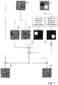
- FIG. 7 is a diagram for describing the processing in the second embodiment.
- FIG. 8 is a diagram for describing the processing in the third embodiment.
- FIGS. 9A and 9B are diagrams for describing the principle of the third embodiment, with the horizontal axis in FIGS. 9A and 9B representing the spatial frequency and the vertical axis representing the amplitude.
- FIG. 10 is a block diagram illustrating a functional configuration of an image generation apparatus 8 according to a fourth embodiment.
- FIG. 11 is a block diagram illustrating a functional configuration of an image generation apparatus 9 according to a fifth embodiment.
- FIG. 12 is a diagram for describing orientation ⁇ ⁇ in the space domain.
- FIG. 13 is a diagram for illustrating images under processing.
- FIG. 14 is a diagram for illustrating images under processing.
- FIGS. 15A and 15B are conceptual diagrams for illustrating image presentation systems 4 and 5 .
- FIGS. 16A and 16B are conceptual diagrams for illustrating image presentation systems 6 and 7 .
- This embodiment achieves a desired binocular parallax by utilizing phase change, rather than position change. Since a position change can be redefined as a phase change of a spatial frequency domain component, a binocular parallax can be converted to a phase difference (a phase parallax). A phase parallax in a certain direction in each spatial frequency domain component is determined as a function of its orientation and spatial frequency. Accordingly, when a certain binocular parallax is desired, it can be converted to a phase change of each spatial frequency domain component, which depends on its orientation and spatial frequency.
- phase-modulated images which are based on elements generated by changing the phase of an “original image” in the positive direction and the negative direction, respectively (an image containing phase-modulated components a and an image containing phase-modulated components b) are added to the “original image” to generate an image A and an image B, which are then presented to the right and left eyes, respectively.
- This can give a phase parallax to an observer wearing “stereoscopic equipment” such as goggles, making the observer perceive an image with an apparent depth.
- stereo equipment such as goggles
- an original image 1000 is a sinusoidal image composed of a single spatial frequency component.
- the vertical spatial frequency of the original image 1000 is zero and the horizontal spatial frequency is a positive value or a negative value.
- a phase-modulated image 1100 (the image containing phase-modulated components a) is prepared by changing the phase of the original image 1000 in the horizontal direction by 0.5 ⁇ [rad] (the phase shifted horizontally in FIG. 1 )
- a phase-modulated image 1200 (the image containing phase-modulated components b) is prepared by changing the phase of the original image 1000 in the horizontal direction by ⁇ 0.5 ⁇ [rad].
- the problem of how to determine the phase change amounts is discussed later.
- An added image 1110 (image A) is obtained by adding (superposing) the phase-modulated image 1100 on the original image 1000 and an added image 1210 (image B) is obtained by adding the phase-modulated image 1200 to the original image 1000 .
- the added image 1110 is presented to one eye (for example, the right eye) of an observer I wearing the “stereoscopic equipment”, while the added image 1210 is presented to the other eye (for example, the left eye) of the observer I.
- the observer I perceives a stereo image by his/her brain utilizing the phase difference between the added image 1110 and the added image 1210 caused by the phase difference between the phase-modulated image 1100 and the phase-modulated image 1200 as a binocular parallax.
- phase-modulated images 1100 , 1200 are sinusoidal images with their phases inverted from each other. That is, in the phase-modulated images 1100 , 1200 , the vectors of pixel value variation are opposite to each other with respect to an intermediate value in a range that can be assumed by pixels.
- the added images 1110 , 1210 being presented are quickly toggled in the time division approach, the image intensities of the phase-modulated components based on those phase-modulated images 1100 , 1200 are averaged or canceled (weakened) together when perceived.
- an observer II who sees both the added images 1110 , 1210 with the same eye(s) (one eye or both eyes) without wearing the “stereoscopic equipment” perceives the components based on the phase-modulated images 1100 , 1200 as uniform, intermediate luminance images.
- the components based on the phase-modulated images 1100 , 1200 are also perceived as uniform, intermediate luminance images by the observer II.
- the image components based on the phase-modulated images 1100 , 1200 are not perceived by the observer II without the “stereoscopic equipment” but only the image components of the original image 1000 , which are components common to the added images 1110 , 1210 presented to the right and left eyes, will be perceived.
- an observer not wearing goggles sees colors that are based on the two channel intensities as they are.
- the present scheme only a change in hue associated with the average intensity of the two channels is perceived over the original image 1000 .
- phase change amounts of the phase-modulated images 1100 and 1200 relative to the original image 1000 are described as being 0.5 ⁇ and ⁇ 0.5 ⁇ [rad], respectively, this is not an essential condition.
- a greater phase change amount may be used for giving a greater depth or a smaller phase change amount may be used for giving a smaller depth.
- the observer II is less likely to perceive a doubled image as the phase change amounts of the phase-modulated images 1100 and 1200 are closer to 0.5 ⁇ and ⁇ 0.5 ⁇ [rad], respectively, and can get an impression of luminance and color contrast close to those of the original image 1000 by fusing the two images in the brain.
- the added images 1110 and 1210 are obtained by adding the phase-modulated images 1100 and 1200 to the original image 1000 , respectively. Accordingly, the luminance contrasts of the added images 1110 and 1210 do not agree with that of the original image 1000 . However, when the added images 1110 and 1210 presented to the right and left eyes respectively are fused, the disagreement of luminance contrast is not as annoying as when they are seen with one eye. This is presumably because the brain has a mechanism to ignore (compensate for) the disagreement of luminance contrast when the added images 1110 , 1210 are fused so as to be consistent with the depth of an image that is perceived due to the phase changes of the two images.
- FIG. 1 showed a method for giving a uniform phase parallax to a sinusoidal image.
- a typical image contains image components of various spatial frequencies and/or orientations. It is thus difficult to give an impression of a desired depth to an image without considering the influence of the spatial frequency or orientation of each pixel component.
- the ground for this idea is discussed from two aspects: spatial frequency and orientation.
- phase parallax To give a desired phase parallax, it is necessary to consider the relation between space dimension and phase dimension relating to the phase parallax amount, such as a relation that a phase modulation of 0.05 ⁇ is required for giving a two-pixel parallax.
- This relation varies with the spatial frequency. For example, even with the same phase change amount, the spatial movement amount of an original image that is a sine wave of 64 pixels per period is greater than the spatial movement amount of an original image that is a sine wave of 16 pixels per period ( FIG. 2 ). This is because a spatial wavelength shortens as the spatial frequency is higher.
- the spatial movement amount when the phase of the sine wave of 64 pixels per period is changed by an amount equivalent to one wavelength is equal to the spatial movement amount when the phase of the sine wave of 16 pixels per period is changed by an amount equivalent to four wavelengths.
- the relation between the space dimension and the phase dimension relating to phase parallax amount is considered from this respect. For instance, to obtain a phase-modulated image moved by two pixels relative to an original image being a sine wave of 64 pixels per period, a phase change of (2/64) ⁇ 2 ⁇ [rad], that is, (1/16) ⁇ [rad], is required.
- phase change amount corresponding to a parallax amount to be given has to be manipulated in accordance with the spatial frequency.
- a phase change amount necessary for moving an image component in the horizontal direction by a certain amount in the space domain depends on the orientations of the spatial frequency components forming the image component. That is, the movement amount of an image component in the horizontal direction in the space domain can be regarded as a combined vector of the movement vectors of the spatial frequency components forming that image component. Thus, the degree of contribution to movement of the image component in the horizontal direction depends on the orientation of each spatial frequency component.
- the term “the orientation of a spatial frequency component” means the orientation at which the spatial frequency of the spatial frequency component is zero in the spatial frequency domain (excluding a case where the spatial frequencies in all the orientations are zero).
- the term “the orientation of a spatial frequency component” means an angle of a lattice (that is, stripes) in a space domain composed of that spatial frequency component relative to the vertical orientation.
- the orientation of a spatial frequency component is the vertical orientation
- the vertical spatial frequency of the spatial frequency component is zero.
- the orientation of a spatial frequency component is the horizontal orientation
- the horizontal spatial frequency of the spatial frequency component is zero. Decomposing the movement vector of an image component in the horizontal direction according to the orientations of the spatial frequency components forming the image component, the magnitude (position change amount) of the movement vector of the spatial frequency component with the vertical orientation is largest, and a spatial frequency component having an orientation closer to the horizontal orientation has a movement vector of a smaller magnitude.
- FIGS. 3A to 3C This is described more specifically using a sine wave ( FIGS. 3A to 3C ).
- the phase change amount of the spatial frequency component of the vertical orientation is greatest, a spatial frequency component closer to the horizontal orientation has a smaller phase change amount, and no phase change is seen for the spatial frequency component of the horizontal orientation. From this regard, the orientation of each spatial frequency component needs to be considered in order to give a desired horizontal parallax via phase modulation.
- this embodiment generates added images (image A and image B) by superposing phase-modulated images (the image containing phase-modulated components a and the image containing phase-modulated components b) on the original image. Further, for creation of phase-modulated images having a desired parallax in the horizontal direction as mentioned above, it is necessary to create the phase-modulated images in consideration of the orientation and spatial frequency of each spatial frequency component.
- the description herein shows a method of manipulating the amplitudes of spatial frequency components (for example, two-dimensional Fourier components) of phase-modulated images such that added images will have a desired parallax when the phase-modulated images are added to the original image, and further a method of manipulating the amplitudes of the spatial frequency and the orientation using weights corresponding to the spatial frequency and the orientation.
- spatial frequency components for example, two-dimensional Fourier components
- the phase-modulated images (the image containing phase-modulated components a and the image containing phase-modulated components b), and the added images (image A and image B) are simple sine waves.
- addition of the original image and a phase-modulated image can be regarded as addition of two sine waves of the same spatial frequency.
- C 1 , C 2 , and C 3 are the amplitudes of the original image, the phase-modulated image, and the added image, respectively.
- F is spatial frequency
- ⁇ , ⁇ , and ⁇ are the phases of the original image, the phase-modulated image, and the added image, respectively
- x represents the horizontal coordinates in the space domain.
- the following describes a way for changing the amplitudes of the spatial frequency components of the phase-modulated components contained in a phase-modulated image in accordance with the spatial frequency and orientation, thereby manipulating the phases of the spatial frequency components of an added image resulting from superposition of the original image and the phase-modulated components, and resulting in giving a consistent parallax in the horizontal direction.
- phase change amount that will produce the desired parallax amount in the space dimension is dependent on the spatial frequency. That is, as illustrated in FIG. 2 , even for giving the same parallax amount, a spatial frequency component with a lower spatial frequency involves a smaller phase change amount for that purpose. It is hence necessary to set the phase change amount corresponding to the desired parallax per spatial frequency. This embodiment achieves this by adjusting the amplitude of a phase-modulated image in the spatial frequency domain (for example, two-dimensional Fourier space).
- varying C 2 with fixed C 1 causes a change in ⁇ . Specifically, as C 2 is smaller than C 1 , ⁇ becomes smaller; and as C 2 is greater than C 1 , ⁇ becomes greater.
- the amplitude of each spatial frequency component of the phase-modulate image is adjusted in accordance with its spatial frequency such that each spatial frequency component of an added image will have a phase change amount corresponding to the desired parallax amount.
- critical spatial frequency The highest one of the spatial frequencies for which the desired parallax amount can be given by the change of the phase.
- the phase change amount of a component with a lower spatial frequency than the critical spatial frequency has to be smaller than the phase change amount of a component of the critical spatial frequency.
- the amplitude of a phase-modulated image component with a lower spatial frequency than the critical spatial frequency is made small.
- d ⁇ [rad] represents the phase change amount of the critical spatial frequency component of an added image that gives the desired parallax amount
- ⁇ CF) of the added image is d(F/CF) ⁇ [rad].
- CF is the critical spatial frequency (CF>0).
- a component with the spatial frequency F higher than the critical spatial frequency CF (where
- a “contribution rate map Fmap for spatial frequency” for adjusting the amplitude of a phase-modulated image in accordance with the spatial frequency is defined.
- Fmap is a two-dimensional array (a two-dimensional gradation image) having I(u, v) that satisfies 0 ⁇ I(u, v) ⁇ 1 as the elements (pixels).
- u represents the horizontal spatial frequency
- v represents the vertical spatial frequency, where u min ⁇ u ⁇ u max , v min ⁇ v ⁇ v max , u min ⁇ u max , and v min ⁇ v max are satisfied.
- I(u, v) represents the weight (contribution rate) corresponding to the spatial frequency component of (u, v).
- FIG. 4A illustrates an example of Fmap.
- the magnitude of I(u, v) is represented with gradation of color, with a brighter color indicating a greater I(u, v) (closer to 1).
- the vertical axis in FIG. 4A represents the spatial frequency axis of the horizontal orientation component (the axis of a vertical spatial frequency v), and the horizontal axis represents the spatial frequency axis of the vertical orientation component (the axis of a horizontal spatial frequency u).
- the spatial frequency is lower as it is closer to the center (a spatial frequency with a smaller absolute value) and is higher as it is closer to an edge (a spatial frequency with a greater absolute value).
- FIG. 4A the magnitude of I(u, v) is represented with gradation of color, with a brighter color indicating a greater I(u, v) (closer to 1).
- the vertical axis in FIG. 4A represents the spatial frequency axis of the horizontal orientation component (the axis of a
- Fmap is used in the spatial frequency domain (for example, two-dimensional Fourier space).
- phase change amount of the spatial frequency component of the vertical orientation is greatest, a spatial frequency component closer to the horizontal orientation has a smaller phase change amount, and no phase change is seen for the spatial frequency component of the horizontal orientation ( FIG. 3 ). Accordingly, it is necessary to manipulate the phase change amount also according to the orientation of a spatial frequency component.
- a “contribution rate map Omap for orientation” for adjusting the amplitude of a phase-modulated image in accordance with orientation is defined.
- Omap is a two-dimensional array (a two-dimensional gradation image) having J(u, v) that satisfies 0 ⁇ J(u, v) ⁇ 1 as the elements (pixels).
- J(u, v) represents the weight (contribution rate) corresponding to the orientation of the spatial frequency component of (u, v).
- FIG. 4B illustrates an example of Omap.
- the magnitude of J(u, v) is represented with gradation of color, with a brighter color indicating a greater J(u, v) (closer to 1).
- the vertical axis in FIG. 4B represents the spatial frequency axis of the horizontal orientation component (the axis of the vertical spatial frequency v), and the horizontal axis represents the spatial frequency axis of the vertical orientation component (the axis of the horizontal spatial frequency u).
- the spatial frequency is lower as it is closer to the center (a spatial frequency with a smaller absolute value) and is higher as it is closer to an edge (a spatial frequency with a greater absolute value).
- J(u, v) is greater for an orientation with the absolute value of the vertical spatial frequency v being closer to zero (an orientation closer to the vertical orientation)
- An image generation apparatus of this embodiment changes the phase of an original image m 0 in the positive direction of the horizontal axis to obtain a phase-modulated image m 1 , and changes the phase of the original image m 0 in the negative direction of the horizontal axis to obtain a phase-modulated image m 2 .
- the image generation apparatus then converts the phase-modulated image m 1 and phase-modulated image m 2 to images FM 1 and FM 2 in the spatial frequency domain by two-dimensional FFT and the like.
- the image generation apparatus further obtains an image FWM 1 by multiplying an image generated by changing the phase of the image FM 1 in the positive direction (for example, shifting the phase by 0.5 ⁇ [rad]) by Fmap and Omap, and obtains an image FWM 2 by multiplying an image generated by changing the phase of the image FM 2 in the negative direction (for example, shifting the phase by ⁇ 0.5 ⁇ [rad]) by Fmap and Omap.
- the image generation apparatus then converts the images FWM 1 and FWM 2 into the space domain by inverse two-dimensional FFT and the like to obtain phase-modulated components wm 1 and wm 2 .
- the added images add 1 and add 2 are displayed on a display device or projected on a screen and the like from a projection device.
- the m 0 component of add 1 and the m 0 component of add 2 have the same coordinates; there is no parallax between these components.
- the observer I wearing the “stereoscopic equipment” sees the phase-modulated image add 1 with one eye and the phase-modulated image add 2 with the other eye. The observer I thereby perceives a stereo image with an apparent depth.
- the observer II not wearing the “stereoscopic equipment” sees the phase-modulated images add 1 and add 2 with the same eye(s) (one eye or both the eyes).
- the observer II perceives the wm 1 component of add 1 and the wm 2 component of add 2 as being canceled or averaged together.
- the observer II thereby perceives a clear planar image of the original image m 0 .
- FIG. 5 an exemplary configuration of an image generation apparatus 1 based on the principle described above is described.
- the image generation apparatus 1 includes a storage 11 , a spatial frequency domain converter 12 , phase manipulators 13 a , 13 b , a weighting unit 14 , combining units 15 a , 15 b , a space domain converter 16 , and superposition units 17 a , 17 b .
- the spatial frequency domain converter 12 , the phase manipulator 13 a , the weighting unit 14 , and the space domain converter 16 correspond to a “first manipulator”
- the spatial frequency domain converter 12 , the phase manipulator 13 b , the weighting unit 14 , and the space domain converter 16 correspond to a “second manipulator”.
- the superposition unit 17 a corresponds to the “first superposition unit”
- the superposition unit 17 b corresponds to the “second superposition unit”.
- the image generation apparatus 1 is an apparatus embodied by execution of a predetermined program by a general- or special-purpose computer having a processor (hardware processor) such as a central processing unit (CPU), memories such as random-access memory (RAM) and read-only memory (ROM), and the like, for example.
- the computer may have one processor and one memory or have multiple processors and memories.
- the program may be installed on the computer or pre-recorded on the ROM and the like.
- some or all of the processing units may be embodied using an electronic circuit that implements processing functions without using programs, rather than an electronic circuit (circuitry) that implements functional components by loading of programs like a CPU.
- an electronic circuit constituting a single apparatus may include multiple CPUs.
- the “contribution rate map Fmap for spatial frequency” and the “contribution rate map Omap for orientation” described above are stored in the storage 11 .
- an original image 100 is first input to the spatial frequency domain converter 12 .
- the original image 100 may be a still image or an image of each frame of a moving image, and may be read from an external storage device or from a storage device (not shown) of the image generation apparatus 1 .
- the spatial frequency domain converter 12 converts the original image 100 to an original image 100 ′ in the spatial frequency domain by two-dimensional FFT and the like (step S 12 ).
- the phase manipulator 13 a takes the original image 100 ′ in the spatial frequency domain as input, and obtains first phase information, which represents phases resulting from shifting (changing) the phases at the respective (u, v) calculated from the original image 100 ′ (spatial frequencies in the respective orientations) by 0.5 ⁇ [rad]. For example, the phase manipulator 13 a adds 0.5 ⁇ [rad] to the phases lying in the first and fourth quadrants of the phase space, and adds ⁇ 0.5 ⁇ [rad] to the phases lying in the second and third quadrants of the phase space. If the phase after the addition is outside the range of ⁇ 0.5 ⁇ to 0.5 ⁇ [rad], the phase manipulator 13 a converts the phase after the addition to a phase within the range by phase coupling (phase unwrapping). The phase manipulator 13 a outputs the first phase information representing the phases at the respective (u, v) thus obtained (step S 13 a ).
- the phase manipulator 13 b takes the original image 100 ′ in the spatial frequency domain as input and obtains second phase information, which represents phases resulting from shifting (changing) the phases at the respective (u, v) calculated from the original image 100 ′ by ⁇ 0.5 ⁇ [rad]. For example, the phase manipulator 13 b adds ⁇ 0.5 ⁇ [rad] to the phases lying in the first and fourth quadrants of the phase space, and adds 0.5 ⁇ [rad] to the phases lying in the second and third quadrants of the phase space. If the phase after the addition is outside the range of ⁇ 0.5 ⁇ to 0.5 ⁇ [rad], the phase manipulator 13 b converts the phase after the addition to a phase within the range by phase coupling. The phase manipulator 13 b outputs the second phase information representing the phases at the respective (u, v) thus obtained (step S 13 b ).
- the weighting unit 14 takes the original image 100 ′ in the spatial frequency domain as input, and multiplies the amplitude at each (u, v) of the original image 100 ′ by the element at that (u, v) in the Fmap and Omap read from the storage 11 to obtain a weighted amplitude representing the amplitude at that (u, v) with a weight. That is, the weighting unit 14 provides each spatial frequency component of an image obtained by changing the phase of the original image with the weight corresponding to the spatial frequency of the spatial frequency component and the weight corresponding to the orientation of the spatial frequency component.
- the weight corresponding to a certain spatial frequency F 1 (the first spatial frequency) is smaller than the weight corresponding to a spatial frequency F 2 (the second spatial frequency) higher than spatial frequency F 1 (that is, F 2 >F 1 ) ( FIG. 4A ).
- a weight corresponding to a spatial frequency (hereinafter weight M) corresponds to the Fmap
- a weight corresponding to an orientation (hereinafter weight N) corresponds to the Omap.
- Every weight M that corresponds to a spatial frequency band higher than the critical spatial frequency CF may be set to 1. Also, the weight N may be from 0 to 1, inclusive.
- the weight M corresponding to a spatial frequency band higher than the critical spatial frequency CF is 1, the weight corresponding to a certain spatial frequency F 1 (the first spatial frequency) is equal to or smaller than the weight corresponding to the spatial frequency F 2 (the second spatial frequency) higher than the spatial frequency F 1 (that is, F 2 >F 1 ).
- the weighting unit 14 outputs weighted amplitude information representing the weighted amplitudes at the respective (u, v) (step S 14 ).
- the combining unit 15 a takes the first phase information and the weighted amplitude information as input and obtains and outputs a combined image 110 ′.
- the element at each (u, v) of the combined image 110 ′ has the phase represented by the first phase information and the amplitude represented by the weighted amplitude information (step S 15 a ).
- the combining unit 15 b takes the second phase information and the weighted amplitude information as input and obtains and outputs a combined image 120 ′.
- the element at each (u, v) of the combined image 120 ′ has the phase represented by the second phase information and the amplitude represented by the weighted amplitude information (step S 15 b ).
- the space domain converter 16 takes the combined image 110 ′ as input, converts the combined image 110 ′ to a phase-modulated image 110 in the space domain (the image containing phase-modulated components a) by inverse two-dimensional FFT and the like, and outputs it.
- the space domain converter 16 similarly takes the combined image 120 ′ as input, converts the combined image 120 ′ to a phase-modulated image 120 in the space domain (the image containing phase-modulated components b) by inverse two-dimensional FFT and the like, and outputs it (step S 16 ).
- the phase-modulated image 110 is based on elements that are obtained by changing the phase of the original image 100 in the positive direction, while the phase-modulated image 120 is based on elements that are obtained by changing the phase of the original image 100 in the negative direction.
- the phase change amount of the phase-modulated image 110 relative to the original image 100 is 0.5 ⁇ [rad]
- the phase change amount of the phase-modulated image 120 relative to the original image 100 is ⁇ 0.5 ⁇ [rad]. That is, the opposite phase of the phase of the phase-modulated image 110 relative to the original image 100 or a neighborhood of the opposite phase is the same as the phase of the phase-modulated image 120 relative to the original image 100 .
- the superposition unit 17 a takes the original image 100 and the phase-modulated image 110 as input, obtains an added image 111 (image A) by superposing the phase-modulated image 110 on the original image 100 , and outputs it.
- the superposition unit 17 b takes the original image 100 and the phase-modulated image 120 as input, obtains an added image 121 (image B) by superposing the phase-modulated image 120 on the original image 100 , and outputs it.
- the added images 111 , 121 are displayed on a display device or projected on a screen and the like from a projection device. Note that add 1 (x, y) and add 2 (x, y) are displayed or projected at the same coordinates as each other or at coordinates close to each other.
- the observer I wearing the “stereoscopic equipment” sees the added image 111 with one eye and the added image 121 with the other eye. The observer I thereby perceives a stereo image with an apparent depth. Meanwhile, the observer II not wearing the “stereoscopic equipment” sees the added images 111 , 121 with the same eye(s) (one eye or both eyes).
- the observer II perceives the phase-modulated image 110 component of the added image 111 and the phase-modulated image 120 component of the added image 121 as being canceled or averaged together. The observer II thereby perceives a clear planar image of the original image 100 .
- the image generation apparatus 1 may output the phase-modulated image 110 as the “image containing phase-modulated components a” and the phase-modulated image 120 as the “image containing phase-modulated components b”.
- Such “image containing phase-modulated components a” and “image containing phase-modulated components b” may be superposed on the original image 100 displayed or printed or on a “subject” represented by the original image 100 (for example, a solid or planar object photographed in the original image). In such a case, the observer I also perceives a stereo image with an apparent depth and the observer II perceives a clear image of the “subject”.
- the “phase-modulated components a” may contain only the luminance components of the phase-modulated image 110 and the “phase-modulated components b” may contain only the luminance components of the phase-modulated image 120 .
- the image generation apparatus 1 may extract only the luminance components of the phase-modulated image 110 to obtain the “phase-modulated components a” and extract only the luminance components of the phase-modulated image 120 to obtain the “phase-modulated components b”.
- the image generation apparatus 1 may output such “image containing phase-modulated components a” and “image containing phase-modulated components b”.
- Such “image containing phase-modulated components a” and “image containing phase-modulated components b” may be superposed on the original image 100 displayed or printed or on a “subject” represented by the original image 100 (for example, a solid or planar object photographed in the original image).
- a “subject” represented by the original image 100 for example, a solid or planar object photographed in the original image.
- the observer I also perceives a stereo image with an apparent depth and the observer II perceives a clear image of the “subject”.
- This embodiment gives different phase differences to different image regions of the original image and different depths to different image regions.
- a “depth map Dmap”, which explicitly indicates what depths are to be given to the original image, is required.
- the Dmap is a two-dimensional array (two-dimensional gradation image) having d(x, y) as the elements (pixels).
- the size of the Dmap is the same as the size of the original image; x represents the horizontal coordinate in the space domain, and y represents the vertical coordinate in the space domain, where x min ⁇ x ⁇ x max , y min ⁇ y ⁇ y max , x min ⁇ x max , and y min ⁇ y max are satisfied.
- d(x, y) is one of a positive value, a negative value, and zero.
- a brighter region indicates a greater depth on the side closer to the observer and a darker region indicates a greater depth on the side farther from the observer. That is, a region with d(x, y)>0 represents a depth on the side closer to the observer, while a region with d(x, y) ⁇ 0 represents a depth on the side farther from the observer, and a greater absolute value Id(x, y) means a greater depth.
- a desired depth can be given to each image region. The following description focuses on the differences from the first embodiment and employs already used reference characters for matters common to the first embodiment for the sake of simplicity.
- an image generation apparatus 2 includes storages 11 , 21 , the spatial frequency domain converter 12 , the phase manipulators 13 a , 13 b , weighting units 14 , 27 , the combining units 15 a , 15 b , the space domain converter 16 , the superposition units 17 a , 17 b , and a decomposition unit 22 .
- the spatial frequency domain converter 12 , the phase manipulator 13 a , the weighting units 14 , 27 , the space domain converter 16 , and the decomposition unit 22 correspond to the “first manipulator”
- the spatial frequency domain converter 12 , the phase manipulator 13 b , the weighting units 14 , 27 , the space domain converter 16 , and the decomposition unit 22 correspond to the “second manipulator”.
- the image generation apparatus 2 is an apparatus embodied by execution of a predetermined program by the aforementioned computer, for example.
- the depth map Dmap (a depth map 201 ) described above is stored in the storage 21 .
- of the elements of the depth map 201 are set in the phase manipulators 13 a , 13 b , respectively.
- the phase change amount for the phase manipulator 13 a is set to 0.5 ⁇ [rad]
- the phase change amount for the phase manipulator 13 b is set to ⁇ 0.5 ⁇ [rad].
- the image generation apparatus 2 Upon start of processing, the image generation apparatus 2 performs the processes at steps S 12 , S 13 a , S 13 b , S 14 , S 15 a , S 15 b , and S 16 described in the first embodiment on an original image 200 instead of the original image 100 to obtain phase-modulated images 210 , 220 instead of the phase-modulated images 110 , 120 .
- the phase-modulated image 210 is generated by changing the phase of the original image 200 in the positive direction and giving a weight
- the phase-modulated image 220 is generated by changing the phase of the original image 200 in the negative direction and giving a weight ( FIG. 7 ).
- the decomposition unit 22 generates a positive contrast map 260 that has the absolute values of the positive components d(x, y)>0 of the depth map Dmap read from the storage 21 as its elements and a negative contrast map 270 that has the absolute values of the negative components d(x, y) ⁇ 0 as its elements, and outputs them.
- the positive contrast map 260 is a two-dimensional array (two-dimensional image) in which the pixel value at coordinate (x, y) with d(x, y)>0 is represented as
- the negative contrast map 270 is a two-dimensional array (two-dimensional image) in which the pixel value at coordinate (x, y) with d(x, y) ⁇ 0 is represented as
- the sizes of the positive contrast map 260 and the negative contrast map 270 are the same as the size of Dmap (step S 22 ).
- the weighting unit 27 takes the phase-modulated images 210 , 220 , the positive contrast map 260 , and the negative contrast map 270 as input, and obtains a phase-modulated image 210 ′ by multiplying the phase-modulated image 210 and the positive contrast map 260 together and also obtains a phase-modulated image 220 ′ by multiplying the phase-modulated image 220 and the negative contrast map 270 together.
- the pixel value at coordinate (x, y) of the phase-modulated image 210 ′ is the result of multiplying the pixel value at the coordinate (x, y) of the phase-modulated image 210 and the pixel value at the coordinate (x, y) of the positive contrast map 260 together.
- the pixel value at coordinate (x, y) of the phase-modulated image 220 ′ is the result of multiplying the pixel value at the coordinate (x, y) of the phase-modulated image 220 and the pixel value at the coordinate (x, y) of the negative contrast map 270 together.
- the weighting unit 27 further obtains a phase-modulated image 230 by adding the phase-modulated image 210 ′ and the phase-modulated image 220 ′.
- the pixel value at coordinate (x, y) of the phase-modulated image 230 is the result of adding the pixel value at the coordinate (x, y) of the phase-modulated image 210 ′ and the pixel value at the coordinate (x, y) of the phase-modulated image 220 ′.
- the weighting unit 27 sends the phase-modulated image 230 to the superposition unit 17 a and sends a sign-inverted image of the phase-modulated image 230 to the superposition unit 17 b .
- the phase-modulated image 230 corresponds to the “image containing phase-modulated components a”, which are obtained by providing the respective “first regions” of an image generated by changing the phase of the original image 200 with at least the weights corresponding to the respective “first regions”.
- the sign-inverted image of the phase-modulated image 230 corresponds to the “image containing phase-modulated components b”, which are obtained by providing the respective “second regions” of an image generated by changing the phase of the original image 200 with at least the weights corresponding to the respective “second regions” (step S 27 ).
- the superposition unit 17 a takes the original image 200 and the phase-modulated image 230 as input, obtains an added image 211 (image A) by superposing the phase-modulated image 230 on the original image 200 , and outputs it (step S 17 a ).
- the superposition unit 17 b takes the original image 200 and the sign-inverted image of the phase-modulated image 230 as input, obtains an added image 221 (image B) by superposing the sign-inverted image of the phase-modulated image 230 on the original image 200 , and outputs it (step S 17 b ).
- the image generation apparatus 2 may output the phase-modulated image 230 as the “image containing phase-modulated components a” and the sign-inverted image of the phase-modulated image 230 as the “image containing phase-modulated components b”.
- Such “image containing phase-modulated components a” and “image containing phase-modulated components b” may be superposed on the original image 200 displayed or printed or on a “subject” corresponding to the original image 200 (the subject represented by the original image 200 ). In such a case, the observer I also perceives a stereo image with an apparent depth and the observer II perceives a clear image of the “subject”.
- the “image containing phase-modulated components a” may contain only the luminance components of the phase-modulated image 230
- the “image containing phase-modulated components b” may contain only the luminance components of the sign-inverted image of the phase-modulated image 230
- the image generation apparatus 2 may extract only the luminance components of the phase-modulated image 230 to obtain the “image containing phase-modulated components a” and extract only the luminance components of the sign-inverted image of the phase-modulated image 230 to obtain the “image containing phase-modulated components b”.
- the image generation apparatus 2 may output such “image containing phase-modulated components a” and “image containing phase-modulated components b”.
- Such “image containing phase-modulated components a” and “image containing phase-modulated components b” may be superposed on the original image 200 displayed or printed or on a “subject” corresponding to the original image 200 (the subject represented by the original image 200 ).
- the observer I also perceives a stereo image with an apparent depth and the observer II perceives a clear image of the “subject”.
- the positive contrast map 260 and the negative contrast map 270 may be generated in advance and stored in the storage 21 .
- the decomposition unit 22 and step S 22 may be omitted.
- This embodiment also gives different phase differences to different image regions of the original image and different depths to different image regions.
- This embodiment performs processing that takes into account the correspondence between the spatial frequency of a phase-modulated image and the spatial frequency of the depth map 201 . An advantage of considering this correspondence is discussed first.
- phase-modulated image When a phase-modulated image is weighted using a depth map having spatial frequencies higher than the spatial frequencies of the phase-modulated image, high spatial frequency components that are not present in the original image will be generated. Superposing such a weighted phase-modulated image on the original image can negatively affect the way the original image looks. This will be explained taking a case of weighting a sinusoidal phase-modulated image using a sinusoidal depth map as an example ( FIGS. 9A and 9B ). When the spatial frequencies of the phase-modulated image are higher than the spatial frequencies of the depth map, the wavelength of the phase-modulated image is shorter than the wavelength of the depth map ( FIG. 9A ).
- the positive/negative (contrast) of the phase-modulated image is not reversed before and after the weighting even with weighting of the phase-modulated image using the depth map.
- the phase can be smoothly changed in term of space, enabling a perception of the desired depth.
- the spatial frequencies of the phase-modulated image are lower than the spatial frequencies of the depth map
- the wavelength of the phase-modulated image is longer than the wavelength of the depth map ( FIG. 9B ).
- weighting the phase-modulated image using the depth map gives rise to segments in which the positive/negative (contrast) of the phase-modulated image is reversed before and after the weighting.
- superposition of the weighted phase-modulated image on the original image causes partial inversion of the contrast.
- high spatial frequency components that are not present in the original image would be added, possibly changing the way the original image looks.
- this embodiment separates the depth map and the phase-modulated image per spatial frequency band, and represents the spatial frequency bands of the depth map in the form of phase by utilizing those spatial frequency bands of the phase-modulated image that are higher than the spatial frequency bands of the depth map. Specifically, those spatial frequency bands of the phase-modulated image that are lower than the spatial frequency bands of the depth map are not used. In this manner, the problem above is solved. However, even if high spatial frequency components that are not present in the original image are added, the human's visual system is not necessarily sensitive to such a change. Thus, in some cases, this scheme does not have to be employed, as in the second embodiment.
- an image generation apparatus 3 includes the storages 11 , 21 , the spatial frequency domain converter 12 , the phase manipulators 13 a , 13 b , weighting units 34 , 37 , the combining units 15 a , 15 b , the space domain converter 16 , the superposition units 17 a , 17 b , and decomposition units 32 , 33 .
- the spatial frequency domain converter 12 , the phase manipulator 13 a , the weighting units 34 , 37 , the space domain converter 16 , and the decomposition units 32 , 33 correspond to the “first manipulator”
- the spatial frequency domain converter 12 , the phase manipulator 13 b , the weighting units 34 , 37 , the space domain converter 16 , and the decomposition units 32 , 33 correspond to the “second manipulator”.
- the image generation apparatus 3 is an apparatus embodied by execution of a predetermined program by the aforementioned computer, for example.
- phase change amounts that give the depth corresponding to the maximum of the absolute values
- the image generation apparatus 3 Upon start of processing, the image generation apparatus 3 performs the steps S 12 , S 13 a , and S 13 b described in the first embodiment on the original image 200 instead of the original image 100 to obtain the first phase information and the second phase information.
- Step S 34 is different from step S 14 in that it does not include weighting with the contribution rate map Fmap for spatial frequency. Adjustment of the phase change amounts relating to spatial frequency is performed based on the depth map discussed later.
- the original image 200 ′ in the spatial frequency domain which has been obtained by conversion of the original image 200 to the spatial frequency domain at step S 12 , is input.
- the weighting unit 34 obtains a weighted amplitude by multiplying the amplitude at each (u, v) of the original image 200 ′ by the element at that (u, v) of Omap read from the storage 11 and giving a weight to the amplitude at that (u, v). That is, the weighting unit 34 provides each spatial frequency component of an image generated by changing the phase of the original image with the weight corresponding to the orientation of that spatial frequency component.
- the weighting unit 34 outputs weighted amplitude information representing the weighted amplitudes at the respective (u, v) (step S 34 ).
- the image generation apparatus 3 then performs the processes at steps S 14 , S 15 a , S 15 b , and S 16 described in the first embodiment to obtain phase-modulated images 310 , 320 instead of the phase-modulated images 110 , 120 .
- the phase-modulated image 310 is generated by changing the phase of the original image 200 in the positive direction and giving a weight
- the phase-modulated image 320 is generated by changing the phase of the original image 200 in the negative direction and giving a weight ( FIG. 8 ).
- the decomposition unit 33 takes the phase-modulated images 310 , 320 as input, renders the phase-modulated image 310 in a multi-resolution representation, decomposes it into multiple multi-resolution images 330 - i of different spatial frequency bands, and outputs them.
- level number i is a positive integer index corresponding to each spatial frequency band.
- the decomposition unit 32 renders the phase-modulated images 310 , 320 in a multi-resolution representation of five levels and obtains and outputs five-level multi-resolution images 330 - 1 to 330 - 5 and 340 - 1 to 340 - 5 .
- the pixel value at coordinate (x, y) of the multi-resolution image 330 with level number i is denoted as Pr 1 (i, x, y)
- the pixel value at coordinate (x, y) of the multi-resolution image 340 with level number i is denoted as Pr 2 (i, x, y)
- the pixel value at coordinate (x, y) of the multi-resolution image 350 with level number i is denoted as Pr 3 (i, x, y) (step S 33 ).
- the weighting unit 37 multiplies the multi-resolution image 330 - i , the positive contrast map 360 - i , and a weight w i together to obtain a positive contrast image 380 a - i , and multiplies the multi-resolution image 340 - i , the negative contrast map 370 - i , and the weight w i together to obtain a negative contrast image 380 b - i .
- the spatial frequency bands of the multi-resolution image 330 - i are higher than the spatial frequency bands of the positive contrast map 360 - i . That is, the spatial frequency of the weight represented by each pixel of the positive contrast map 360 - i (the spatial frequency of the weight corresponding to each of the first regions) is lower than the spatial frequency of a pixel of the multi-resolution image 330 - i to which that weight is given (the spatial frequency of each of the first regions). Also, the spatial frequency bands of the multi-resolution image 340 - i are higher than the spatial frequency bands of the negative contrast map 370 - i .
- the spatial frequency of the weight represented by each pixel of the negative contrast map 370 - i (the spatial frequency of the weight corresponding to each of the second regions) is lower than the spatial frequency of a pixel of the multi-resolution image 340 - i to which that weight is given (the spatial frequency of each of the second regions) ( FIG. 9A ).
- the weight w i (where 0 ⁇ w i ⁇ 1) is for adjusting the phase change amounts corresponding to the desired parallax per spatial frequency, as with the contribution rate map for spatial frequency described previously.
- Every weight w i corresponding to a spatial frequency band higher than the critical spatial frequency CF may be set to 1.
- the weighting unit 37 sends the phase-modulated image 390 to the superposition unit 17 a and sends the sign-inverted image of the phase-modulated image 390 to the superposition unit 17 b .
- the phase-modulated image 390 corresponds to the “phase-modulated components a”, which are obtained by providing the respective “first regions” of an image generated by changing the phase of the original image 200 with at least the weights corresponding to the respective “first regions”.
- the sign-inverted image of the phase-modulated image 390 corresponds to the “phase-modulated components b”, which are obtained by providing the respective “second regions” of an image generated by changing the phase of the original image 200 with at least the weights corresponding to the respective “second regions”.
- the spatial frequency of the weight corresponding to each of the “first regions” is lower than the spatial frequency of the “first region”, and the spatial frequency of the weight corresponding to each of “second regions” is lower than the spatial frequency of the “second region” (step S 37 ).
- the superposition unit 17 a takes the original image 200 and the phase-modulated image 390 as input, obtains an added image 311 (image A) by superposing the phase-modulated image 390 on the original image 200 , and outputs it (step S 17 a ).
- the superposition unit 17 b takes the original image 200 and the sign-inverted image of the phase-modulated image 390 as input, obtains an added image 321 (image B) by superposing the sign-inverted image of the phase-modulated image 390 on the original image 200 , and outputs it (step S 17 b ).
- the image generation apparatus 3 may output the phase-modulated image 390 as the “image containing phase-modulated components a” and the sign-inverted image of the phase-modulated image 390 as the “image containing phase-modulated components b”.
- Such “image containing phase-modulated components a” and “image containing phase-modulated components b” may be superposed on the original image 200 displayed or printed or on a “subject” corresponding to the original image 200 (the subject represented by the original image 200 ). In such a case, the observer I also perceives a stereo image with an apparent depth and the observer II perceives a clear planar image of the original image 200 .
- the “image containing phase-modulated components a” may contain only the luminance components of the phase-modulated image 390
- the “image containing phase-modulated components b” may contain only the luminance components of the sign-inverted image of the phase-modulated image 390
- the image generation apparatus 3 may extract only the luminance components of the phase-modulated image 390 to obtain the “image containing phase-modulated components a” and extract only the luminance components of the sign-inverted image of the phase-modulated image 390 to obtain the “image containing phase-modulated components b”.
- the image generation apparatus 3 may output such “image containing phase-modulated components a” and “image containing phase-modulated components b”.
- Such “image containing phase-modulated components a” and “image containing phase-modulated components b” may be superposed on the original image 200 displayed or printed or on a “subject” corresponding to the original image 200 (the subject represented by the original image 200 ).
- the observer I also perceives a stereo image with an apparent depth and the observer II perceives a clear planar image of the original image 200 .
- the positive contrast map 360 - i and the negative contrast map 370 - i may be generated in advance and stored in the storage 21 .
- the decomposition unit 32 and step S 32 may be omitted.
- This embodiment is a modification of the second and third embodiments and also gives different phase differences to different image regions of the original image and different depths to different image regions.
- an image generation apparatus 8 includes decomposition units 811 , 812 , spatial frequency domain converters 821 , 822 , space domain converters 823 , 824 , a weight calculation unit 83 , a phase manipulator 84 , a weighting unit 85 , a reconstruction unit 86 , and superposition units 87 , 88 .
- the decomposition units 811 , 812 , the spatial frequency domain converters 821 , 822 , the space domain converters 823 , 824 , the weight calculation unit 83 , the phase manipulator 84 , the weighting unit 85 , the reconstruction unit 86 , and the superposition unit 87 correspond to the “first manipulator”
- the decomposition units 811 , 812 , the spatial frequency domain converters 821 , 822 , the space domain converters 823 , 824 , the weight calculation unit 83 , the phase manipulator 84 , the weighting unit 85 , the reconstruction unit 86 , and the superposition unit 88 correspond to the “second manipulator”.
- the image generation apparatus 8 is an apparatus embodied by execution of a predetermined program by the aforementioned computer, for example.
- an original image I C ( FIG. 13A ) and the parallax map Dmap described above ( FIG. 13B ) are input.
- the original image I C is a two-dimensional array having I C (x, y) as the elements (pixels).
- the original image I C may be a still image or an image of each frame of a moving image, and may be read from an external storage device or from a storage device (not shown) of the image generation apparatus 8 .
- the parallax map Dmap is a two-dimensional array (a two-dimensional gradation image) having d(x, y) as the elements (pixels).
- the size of Dmap is the same as the size of the original image I C ;
- x represents the horizontal coordinate in space domain, and
- y represents the vertical coordinate in space domain, where x min ⁇ x ⁇ x max , y min ⁇ y ⁇ y max , x min ⁇ x max , and y min ⁇ y max are satisfied.
- d(x, y) is one of a positive value, a negative value, and zero.
- a region with d(x, y)>0 represents a parallax that is seen on the front side of a display surface or screen surface (a crossed parallax), while a region with d(x, y) ⁇ 0 represents a parallax that is seen on the back side of the display surface or screen surface (an uncrossed parallax), where a greater absolute value
- the original image I C is input to the spatial frequency domain converter 821 .
- the spatial frequency domain converter 821 converts the original image I C to an original image I C ⁇ in the spatial frequency domain and outputs the original image I C ⁇ .
- the original image I C ⁇ in the spatial frequency domain is a two-dimensional array having I C ⁇ ( ⁇ x , ⁇ y ) as the elements.
- ⁇ x represents the spatial frequency in the horizontal direction
- ⁇ y represents the spatial frequency in the vertical direction.
- discrete Fourier transform may be used, for example. Note that correctly the superscript “ ⁇ ” of “I C ⁇ ” should be placed immediately above “I”. However, due to limitation of denotation in the specification, “ ⁇ ” may be sometimes placed upper right of “I C ” (step S 821 ).
- the original image I C ⁇ in the spatial frequency domain is input to the decomposition unit 812 .
- the decomposition unit 812 applies a complex steerable filter sequence ⁇ to the original image I C ⁇ to obtain complex steerable pyramids.
- the steerable filter sequence ⁇ is composed of steerable filters ⁇ ⁇ , ⁇ corresponding to a spatial frequency band ⁇ and an orientation band ⁇ .
- ⁇ is an integer index corresponding to a spatial frequency band with a predetermined width
- ⁇ is an integer index corresponding to an orientation band with a predetermined width.
- ⁇ min ⁇ max , ⁇ min ⁇ max , ⁇ min ⁇ max , and ⁇ min ⁇ max are satisfied.
- a smaller value of ⁇ corresponds to a frequency band of a lower frequency.
- the decomposition unit 812 multiplies the original image I C ⁇ by the steerable filter ⁇ ⁇ , ⁇ for all the combinations of ⁇ and ⁇ to obtain complex steerable pyramids S C ⁇ , ⁇ ⁇ corresponding to the respective spatial frequency bands ⁇ and orientation bands ⁇ , and outputs them.
- the complex steerable pyramids S C ⁇ , ⁇ ⁇ are input to the space domain converter 823 .
- the space domain converter 823 converts the complex steerable pyramids S C ⁇ , ⁇ ⁇ to complex steerable pyramids S C ⁇ , ⁇ in the space domain and outputs the complex steerable pyramids S C ⁇ , ⁇ .
- discrete inverse Fourier transform may be used, for example.
- Each complex steerable pyramid S C ⁇ , ⁇ is a two-dimensional array having S C ⁇ , ⁇ (x, y) as the elements (pixels) (step S 823 ).
- the complex steerable pyramids S C ⁇ , ⁇ in the space domain are input to the phase manipulator 84 .
- the phase manipulator 84 extracts the imaginary part Im[S C ⁇ , ⁇ (x, y)] of each complex steerable pyramid Sc., t, obtains a phase-shifted image S C′ ⁇ , ⁇ corresponding to each spatial frequency band ⁇ and each orientation band ⁇ as shown below, and outputs them ( FIG. 13C ).
- each phase-shifted image S C′ ⁇ , ⁇ is a two-dimensional array having S C′ ⁇ , ⁇ (x, y) as the elements (pixels).
- C′ ⁇ , ⁇ means an orientation that corresponds to the component with the strongest power among the orientations contained in the orientation band ⁇ (the peak orientation).
- An example of ⁇ ⁇ is the orientation at the center of the orientation band. As shown in FIG. 12 , ⁇ ⁇ is an angle formed by a lattice in the space domain composed of a certain spatial frequency component relative to the vertical orientation, satisfying 0 ⁇ ⁇ ⁇ .
- the phase of the phase-shifted image S C′ ⁇ , ⁇ is equivalent to the phase of the sinusoidal component corresponding to the spatial frequency band ⁇ and orientation band ⁇ of the original image I C as shifted in the positive direction by 0.5 ⁇ [rad].
- the inversion of the positive/negative sign when ⁇ ⁇ > ⁇ /2 is intended for shifting the phase in the same direction (the positive direction) by 0.51 ⁇ [rad] within the range of 0 ⁇ ⁇ ⁇ /2 and the range of ⁇ ⁇ > ⁇ /2 (step S 84 ).
- the parallax map Dmap input to the image generation apparatus 8 is input to the decomposition unit 811 .
- the decomposition unit 811 applies a Gaussian filter sequence to the parallax map Dmap to obtain Gaussian pyramids G D ⁇ (x, y) of the parallax map Dmap, and outputs them ( FIG. 13D ).
- the Gaussian pyramid G D ⁇ contains the spatial frequencies corresponding to the spatial frequency band ⁇ and spatial frequency bands lower than it. That is, G D ⁇ (x, y) represents the value of each coordinate (x, y) in Gaussian pyramids of the parallax map Dmap that correspond to the spatial frequency band ⁇ corresponding to co and spatial frequency bands lower than the spatial frequency band ⁇ .
- the subscript “D ⁇ ” of “G D ⁇ ” should be denoted as “D ⁇ ”. However, due to limitation of denotation in the specification, it may sometimes be denoted as “D ⁇ ” (step S 811 ).
- the Gaussian pyramids G D ⁇ (x, y) are input to the weight calculation unit 83 .
- the weight calculation unit 83 obtains a weight image A ⁇ , ⁇ , which is a two-dimensional array having the respective weights A ⁇ , ⁇ (x, y) as the elements, as shown below, and outputs it.
- ⁇ ⁇ means a spatial frequency that corresponds to the component with the strongest power among the spatial frequencies contained in the spatial frequency band ⁇ (the peak spatial frequency).
- ⁇ ⁇ is the spatial frequency at the center of the spatial frequency band ⁇ (step S 83 ).
- the phase-shifted image S C′ ⁇ , ⁇ and the weight image A ⁇ , ⁇ are input to the weighting unit 85 .
- the weighting unit 85 multiplies each weight A ⁇ , ⁇ (x, y) of the weight image A ⁇ , ⁇ and the element S C′ ⁇ , ⁇ (x, y) of the phase-shifted image S C′ ⁇ , ⁇ together as shown below to obtain a weighted image S ⁇ circumflex over ( ) ⁇ C′ ⁇ , ⁇ , which is a two-dimensional array having the respective S ⁇ circumflex over ( ) ⁇ C′ ⁇ , ⁇ (x, y) as the elements, and outputs it.
- the weighted image S ⁇ circumflex over ( ) ⁇ C′ ⁇ , ⁇ is input to the spatial frequency domain converter 822 .
- the spatial frequency domain converter 822 converts the weighted image S ⁇ circumflex over ( ) ⁇ C′ ⁇ , ⁇ to a weighted image S ⁇ circumflex over ( ) ⁇ ⁇ C′ ⁇ , ⁇ in the spatial frequency domain, and outputs the weighted image S ⁇ circumflex over ( ) ⁇ ⁇ C′ ⁇ , ⁇ . While the denotation “S ⁇ circumflex over ( ) ⁇ ⁇ C′ ⁇ , ⁇ ” may be sometimes used due to limitation of denotation in the specification, “S ⁇ circumflex over ( ) ⁇ ⁇ C′ ⁇ , ⁇ ” is synonymous with:
- discrete Fourier transform may be used, for example (step S 822 ).
- the weighted image S ⁇ circumflex over ( ) ⁇ ⁇ C′ ⁇ , ⁇ is input to the reconstruction unit 86 .
- the reconstruction unit 86 applies the steerable filter sequence ⁇ described above to the weighted image S ⁇ circumflex over ( ) ⁇ ⁇ C′ ⁇ , ⁇ as shown below to obtain a phase-modulated image I D ⁇ in the spatial frequency domain, and outputs it (step S 86 ).
- I ⁇ D ⁇ ⁇ , ⁇ ⁇ ⁇ ⁇ , ⁇ ⁇ S ⁇ ⁇ C ⁇ , ⁇ ′ ( 8 )
- the phase-modulated image I D ⁇ in the spatial frequency domain is input to the space domain converter 824 .
- the space domain converter 824 converts phase-modulated image I D ⁇ in the spatial frequency domain to a phase-modulated image I D in the space domain and outputs the phase-modulated image I D ( FIG. 13E ).
- the phase-modulated image I D is a two-dimensional array having I D (x, y) as the elements (pixels).
- discrete inverse Fourier transform may be used, for example (step S 824 ).
- the superposition unit 87 takes the original image I C and the phase-modulated image I D as input, and obtains an added image I R (image A) by superposing the sign-inverted image of the phase-modulated image I D (the phase-modulated components a) on the original image I C , and outputs it ( FIG. 13G ).
- the value of the parallax map Dmap is positive (a crossed parallax) in a certain region, the phase of the phase-modulated image I D in the corresponding region has been shifted relative to the phase of the original image I C in the positive direction by 0.5 ⁇ [rad].
- phase of the sign-inverted image of the phase-modulated image I D (the phase-modulated components a) in this region is equivalent to the phase of the original image I C as moved in the negative direction by 0.5 ⁇ [rad].
- the phase of the phase-modulated image I D in the corresponding region has been shifted relative to the phase of the original image I C in the negative direction by 0.5 ⁇ [rad].
- the phase of the sign-inverted image of the phase-modulated image I D (the phase-modulated components a) in this region is equivalent to the phase of the original image I C as moved in the positive direction by 0.5 ⁇ [rad].
- the sign-inverted image of the phase-modulated image I D and the added image I R correspond to the “image containing phase-modulated components a”, which are obtained by providing the respective “first regions” of an image generated by changing the phase of the original image I C with at least the weights corresponding to the respective “first regions” (step S 87 ).
- the superposition unit 88 takes the original image I C and the phase-modulated image I D as input, obtains an added image I L (image B) by superposing the original image I C and the phase-modulated image I D (phase-modulated components b), and outputs it ( FIG. 13F ).
- the phase-modulated components b are the opposite phase image of the phase-modulated components a.
- phase of the phase-modulated components b in this region is equivalent to the phase of the original image I C as moved in the positive direction by 0.5 ⁇ [rad].
- the phase of the phase-modulated image I D in the corresponding region has been shifted relative to the phase of the original image I C in the negative direction by 0.5 ⁇ [rad].
- the phase of the phase-modulated components b in this region is equivalent to the phase of the original image I C as moved in the negative direction by 0.5 ⁇ [rad].
- the pixel value I L (x, y) at each coordinate (x, y) of the added image I L is the sum of the pixel value I C (x, y) at that coordinate (x, y) of the original image I C and the pixel value I D (x, y) at that coordinate (x, y) of the phase-modulated image I D (I L (x, y) ⁇ I C (x, y)+I D (x, y)).
- phase-modulated image I D and the added image I L correspond to the “image containing phase-modulated components b”, which are obtained by providing the respective “second regions” of an image generated by changing the phase of the original image I C with at least the weights corresponding to the respective “second regions” (step S 88 ).
- the maximum parallax between the added images I R , I L is a half wavelength of each wavelength.
- the aforementioned weight A ⁇ , ⁇ (x, y) needs to be infinite, which is not practical.
- the absolute value of the phase shift amounts for the added images I R , I L relative to the original image I C may be both limited to ⁇ /4 [rad] or less.
- the absolute value of the weight A ⁇ , ⁇ (x, y) is 1 or less and the absolute value of the parallax between the added images I R , I L is less than ⁇ /(2 ⁇ ⁇
- the weight calculation unit 83 obtains a weight image A ⁇ , ⁇ which is a two-dimensional array having the respective weights A ⁇ , ⁇ (x, y) as the elements by Formula (9) below instead of Formula (6) and outputs it.
- the weight corresponding to an orientation band ⁇ 1 (the first orientation band) having a certain orientation ⁇ ⁇ 1 as its peak is equal to or smaller than the weight corresponding to an orientation band ⁇ 2 (the second orientation band) having an orientation ⁇ ⁇ 2 closer to the vertical orientation (0 or ⁇ ) than the orientation band ⁇ 1 as its peak (that is,
- the sign-inverted image of the phase-modulated image I D and the phase-modulated image I D are superposed on the original image I C respectively, thereby obtaining the added images I R and I L having a parallax relative to each other.
- the amplitude of the added images I R and I L obtained in this manner is greater than the amplitude of the original image I C , and the added images I R and I L may exceed a predetermined lower limit b L and/or upper limit b U (b L ⁇ b U ), that is, exceed a predetermined dynamic range.
- a simple remedy for this can be linearly compressing the overall intensities of the added images I R and I L in order to confine the added images I R and I L within the range between the lower limit b L and the upper limit b U .
- the contrast of the added images I R and I L becomes smaller than that of the original image I C , altering the impression of the image.
- Another possible remedy is to remove those portions of the added images I R and I L that are outside the lower limit b L and/or upper limit b U . In this case, however, the parallax components of the added images I R and I L are not canceled by each other and a doubly blurred image can be perceived when the added images I R and I L are seen by both eyes at a time.
- phase-modulated images I D corresponding to those portions of the added images I R and I L that are outside the lower limit b L or the upper limit b U are clipped.
- the image generation apparatus 8 further includes a dynamic range adjusting unit 861 ( FIG. 10 ).
- the dynamic range adjusting unit 861 takes the phase-modulated image I D and the added images I R , I L obtained by the superposition units 87 , 88 as input, updates the phase-modulated image I D to a phase-modulated image I D ⁇ circumflex over ( ) ⁇ as shown below, and outputs it.
- the superposition unit 87 further takes the original image I C and the phase-modulated image I D ⁇ circumflex over ( ) ⁇ as input, and obtains an added image I R (image A) by superposing the sign-inverted image of the phase-modulated image I D ⁇ circumflex over ( ) ⁇ (the phase-modulated components a) on the original image I C , and outputs it.
- the added image I R obtained at step S 87 as described above is not output as the image A.
- the superposition unit 88 further takes the original image I C and the phase-modulated image I D ⁇ circumflex over ( ) ⁇ as input, and obtains an added image I L (image B) by superposing the original image I C and the phase-modulated image I D ⁇ circumflex over ( ) ⁇ (phase-modulated components b), and outputs it.
- the added image I L obtained at step S 88 as described above is not output as the image B.
- the image generation apparatus 8 may output the sign-inverted image of the phase-modulated image I D as the “image containing phase-modulated components a” and the phase-modulated image I D as the “image containing phase-modulated components b”.
- Such “image containing phase-modulated components a” and “image containing phase-modulated components b” may be superposed on the original image I C displayed or printed or on a “subject” corresponding to the original image I C (the subject represented by the original image I C ). In such a case, the observer I also perceives a stereo image with an apparent depth and the observer II perceives a clear planar image of the original image I C .
- the “phase-modulated components a” may contain only the luminance components of the sign-inverted image of the phase-modulated image I D
- the “phase-modulated components b” may contain only the luminance components of the phase-modulated image I D .
- the image generation apparatus 8 may extract only the luminance components of the sign-inverted image of the phase-modulated image I D to obtain the “phase-modulated components a” and extract only the luminance components of the phase-modulated image I D to obtain the “phase-modulated components b”.
- the image generation apparatus 8 may output such “image containing phase-modulated components a” and “image containing phase-modulated components b”.
- Such “image containing phase-modulated components a” and “image containing phase-modulated components b” may be superposed on the original image I C displayed or printed or on a “subject” corresponding to the original image I C (the subject represented by the original image I C ).
- the observer I also perceives a stereo image with an apparent depth and the observer II perceives a clear planar image of the original image I C .
- the processes at steps S 821 , S 812 , S 823 , S 84 , S 85 , S 822 , S 86 , S 824 , S 87 , and S 88 in the fourth embodiment may be performed for each of the color channels (R, G, and B channels) and the added images I R (images A) and added images I L (images B) of all the color channels may be output.
- the modifications 1 to 4 of the fourth embodiment may also be implemented where the original image I C is a color image, in which case the processes of modifications 2 and 3 are performed for each color channel.
- the phase-shifted image S C′ ⁇ , ⁇ is generated by shifting the phase of the original image I C in the positive direction by 0.5 ⁇ [rad] (Formula (5)).
- the phase-shifted image S C′ ⁇ , ⁇ may be generated by shifting the phase of the original image I C in the positive direction by a neighborhood of 0.5 ⁇ .
- the phase of a region in the sign-inverted image of the phase-modulated image I D (the phase-modulated components a) that corresponds to a region for which the value of parallax map Dmap is positive (a crossed parallax) is equivalent to a shift in the negative direction by a neighborhood of 0.5 ⁇ [rad] relative to the phase of the original image I C .
- phase of a region in the sign-inverted image of the phase-modulated image I D (the phase-modulated components a) that corresponds to a region for which the value of parallax map Dmap is negative is equivalent to a shift in the positive direction by a neighborhood of 0.5 ⁇ [rad] relative to the phase of the original image I C .
- phase of a region in the phase-modulated image I D (phase-modulated components b) that corresponds to a region for which the value of parallax map Dmap is positive (a crossed parallax) is equivalent to a shift in the positive direction by a neighborhood of 0.5 ⁇ [rad] relative to the phase of the original image I C .
- phase of a region in the phase-modulated image I D (phase-modulated components b) that corresponds to a region for which the value of parallax map Dmap is negative is equivalent to a shift in the negative direction by a neighborhood of 0.5 ⁇ [rad] relative to the phase of the original image I C .
- the phase-modulated components a may be the sign-inverted image of the phase-modulated image I D and the phase-modulated components b may be an image in the neighborhood of the opposite phase of the phase-modulated components a.
- This embodiment shows a method for converting conventional stereo image content to the added image I R (image A) and added image I L (image B).
- a simple method is to calculate the parallax map Dmap from an image having a binocular parallax for conventional stereo image content and use the map to perform the process of the fourth embodiment to obtain the added image I R (image A) and added image I L (image B).
- This embodiment however obtains the added image I R (image A) and added image I L (image B) from conventional stereo image content in a simpler manner without generating the parallax map Dmap.
- an image generation apparatus 9 includes spatial frequency domain converters 822 , 921 , 922 , space domain converters 824 , 924 , 925 , decomposition units 911 , 912 , a phase manipulator 93 , a phase difference calculation unit 94 , a weight calculation unit 95 , the weighting unit 85 , the reconstruction unit 86 , and the superposition units 87 , 88 .
- the spatial frequency domain converters 822 , 921 , 922 , the space domain converters 824 , 924 , 925 , the decomposition units 911 , 912 , the phase manipulator 93 , the phase difference calculation unit 94 , the weight calculation unit 95 , the weighting unit 85 , the reconstruction unit 86 , and the superposition unit 87 correspond to the “first manipulator”
- the spatial frequency domain converters 822 , 921 , 922 , the space domain converters 824 , 924 , 925 , the decomposition units 911 , 912 , the phase manipulator 93 , the phase difference calculation unit 94 , the weight calculation unit 95 , the weighting unit 85 , the reconstruction unit 86 , and the superposition unit 88 correspond to the “second manipulator”.
- the image generation apparatus 9 is an apparatus embodied by execution of a predetermined program by the aforementioned computer, for example.
- an original image I L′ I C (a first original image: FIG. 14A ) and an original image I R′ (a second original image: FIG. 14B ) are input.
- the original image I L′ and the original image I R′ are three-dimensional image content for giving an apparent depth to an image with the conventional binocular image presentation scheme.
- the original image I R′ is a two-dimensional array having I R′ (x, y) as the elements
- the original image I L′ is a two-dimensional array having I L′ (x, y) as the elements (pixels).
- the original image I R′ and original image I L′ may be still images or images of frames of a moving image, and may be read from an external storage device or from a storage device (not shown) of the image generation apparatus 9 .
- the original image I L′ is input to the spatial frequency domain converter 921 and the original image I R′ is input to the spatial frequency domain converter 922 .
- the spatial frequency domain converter 921 converts the original image I L′ to an original image I L′ ⁇ in the spatial frequency domain and outputs the original image I L′ ⁇ .
- the spatial frequency domain converter 922 converts the original image I R′ to an original image I R′ ⁇ in the spatial frequency domain and outputs the original image I R′ ⁇ .
- discrete Fourier transform may be used, for example. Note that correctly the superscript “ ⁇ ” of “I L′ ⁇ ” and “I R′ ⁇ ” should be placed immediately above “I”. However, due to limitation of denotation in the specification, “ ⁇ ” may be sometimes placed upper right of “I L′ ” and “I R′ ” (steps S 921 and S 922 ).
- the original image I L′ ⁇ in the spatial frequency domain is input to the decomposition unit 911 and the original image I R′ ⁇ , in the spatial frequency domain is input to the decomposition unit 912 .
- the decomposition units 911 and 912 apply the complex steerable filter sequence ⁇ to the original images I L′ ⁇ , and I R′ ⁇ , respectively as shown below to obtain complex steerable pyramids S L′ ⁇ , ⁇ ⁇ and S R′ ⁇ , ⁇ ⁇ corresponding to the respective spatial frequency bands ⁇ and orientation bands ⁇ , and outputs them (steps S 911 and S 912 ).
- the complex steerable pyramids S L′ ⁇ , ⁇ ⁇ and S R′ ⁇ , ⁇ ⁇ are input to the space domain converters 924 and 925 , respectively.
- the space domain converters 924 and 925 respectively convert the complex steerable pyramids S L′ ⁇ , ⁇ ⁇ and S R′ ⁇ , ⁇ ⁇ to complex steerable pyramids S L′ ⁇ , ⁇ and S R′ ⁇ , ⁇ in the space domain ( FIGS. 14C and 14D ), and output the complex steerable pyramids S L′ ⁇ , ⁇ and S R′ ⁇ , ⁇ .
- discrete inverse Fourier transform may be used, for example.
- Each complex steerable pyramid S L′ ⁇ , ⁇ is a two-dimensional array having S L′ ⁇ , ⁇ (x, y) as the elements (pixels), and each complex steerable pyramid S R′ ⁇ , ⁇ is a two-dimensional array having S R′ ⁇ , ⁇ (x, y) as the elements (steps S 924 and S 925 ).
- the complex steerable pyramids S L′ ⁇ , ⁇ and S R′ ⁇ , ⁇ are input to the phase difference calculation unit 94 .
- the phase difference calculation unit 94 obtains the phase difference ⁇ ⁇ , ⁇ (x, y) between S L′ ⁇ , ⁇ (x, y) and S R′ ⁇ , ⁇ (x, y) using the method described in Reference Literature 2 (DIDYK, P., SITTHI-AMORN, P., FREEMAN, W., DURAND, F., AND MATUSIK, W. 2013, “Joint View Expansion and Filtering for Automultiscopic 3d Displays,” ACM Trans. Graph. 32, 6737 (November), 221:1-221:8), and outputs it.
- phase difference ⁇ ⁇ , ⁇ A set having the phase difference ⁇ ⁇ , ⁇ (x, y) as the elements is denoted as phase difference ⁇ ⁇ , ⁇ .
- a value twice the phase difference ⁇ ⁇ -1, ⁇ (x, y) for the one-lower spatial frequency band ⁇ 1 is used as the phase difference ⁇ ⁇ , ⁇ (x, y).
- ⁇ ⁇ , ⁇ ( x,y ) 2 ⁇ ⁇ -1, ⁇ ( x,y )
- the peak spatial frequency ⁇ ⁇ of spatial frequency band ⁇ is twice or in the neighborhood of twice the peak spatial frequency ⁇ ⁇ -1 of spatial frequency band ( ⁇ 1) (step S 94 ).
- the phase difference ⁇ ⁇ , ⁇ is input to the weight calculation unit 95 .
- the weight calculation unit 95 obtains weight A ⁇ , ⁇ (x, y) as shown below and outputs it (step S 95 ):
- a ⁇ , ⁇ ( x,y ) tan ⁇ ⁇ , ⁇ ( x,y ) ⁇
- the complex steerable pyramids S L′ ⁇ , ⁇ obtained by the space domain converter 924 are input to the phase manipulator 93 .
- the processes at steps S 85 , S 822 , S 86 , and S 824 described in the fourth embodiment are performed and the space domain converter 824 outputs the phase-modulated image I D ( FIG. 14E ).
- the process at step S 87 described in the fourth embodiment is performed and the superposition unit 87 obtains and outputs the added image I R (image A) ( FIG. 14G ).
- the process at step S 88 described in the fourth embodiment is performed and the superposition unit 88 obtains and outputs the added image I L (image B) ( FIG. 14F ).
- the image generation apparatus 9 FIG. 11 ) further includes a phase difference limiting unit 941 .
- the phase difference limiting unit 941 takes the phase difference ⁇ ⁇ , ⁇ (x, y) obtained by the phase difference calculation unit 94 as input and updates the phase difference ⁇ ⁇ , ⁇ (x, y) to ⁇ circumflex over ( ) ⁇ ⁇ , ⁇ (x, y) as:
- ⁇ ⁇ ⁇ , ⁇ ⁇ ( x , y ) ⁇ ⁇ / 4 if ⁇ ⁇ ⁇ ⁇ ⁇ ⁇ , ⁇ ⁇ ( x , y ) / 2 > ⁇ / 4 - ⁇ / 4 if ⁇ ⁇ ⁇ ⁇ ⁇ ⁇ , ⁇ ⁇ ( x , y ) / 2 ⁇ - ⁇ / 4 ⁇ ⁇ ⁇ ⁇ , ⁇ ⁇ ( x , y ) / 2 otherwise
- ⁇ is a positive constant for scaling.
- step S 95 ⁇ circumflex over ( ) ⁇ ⁇ , ⁇ (x, y) is input to the weight calculation unit 95 instead of phase difference ⁇ ⁇ , ⁇ (x, y).
- the weight calculation unit 95 then obtains the weight A ⁇ , ⁇ (x, y) as below and outputs it.
- a ⁇ , ⁇ ( x,y ) tan ⁇ circumflex over ( ⁇ ) ⁇ ⁇ , ⁇ ( x,y ) ⁇
- the subsequent process is performed as described above.
- the image generation apparatus 9 may further include the dynamic range adjusting unit 861 ( FIG. 11 ).
- the dynamic range adjusting unit 861 updates the phase-modulated image I D to the phase-modulated image I D ⁇ circumflex over ( ) ⁇ and outputs it as described in the modification 2 of the fourth embodiment
- the image generation apparatus 9 may output the sign-inverted image of the phase-modulated image I D as the “image containing phase-modulated components a” and output the phase-modulated image I D as the “image containing phase-modulated components b”.
- the observer I also perceives a stereo image with an apparent depth and the observer II perceives a clear planar image of the original image I C .
- the “phase-modulated components a” may contain only the luminance components of the sign-inverted image of the phase-modulated image I D
- the “phase-modulated components b” may contain only the luminance components of the phase-modulated image I D .
- the image generation apparatus 9 may extract only the luminance components of the sign-inverted image of the phase-modulated image I D to obtain the “phase-modulated components a” and extract only the luminance components of the phase-modulated image I D to obtain the “phase-modulated components b”.
- the image generation apparatus 9 may output such “image containing phase-modulated components a” and “image containing phase-modulated components b”.
- the processes at steps S 921 , S 922 , S 911 , S 912 , S 924 , S 925 , S 95 , S 93 , S 85 , S 822 , S 86 , S 824 , S 87 , and S 88 of the fifth embodiment are performed for each of the color channels (R, G, and B channels) and the added images I R (image A) and added images I L (image B) of all the color channels may be output.
- the process at step S 94 may be performed for only one of the channels.
- phase-modulated components a may be the sign-inverted image of the phase-modulated image I D and the phase-modulated components b being the phase-modulated image I D
- the phase-modulated components a may be the sign-inverted image of the phase-modulated image I D
- the phase-modulated components b may be an image in the neighborhood of the opposite phase of the phase-modulated components a.
- This embodiment illustrates an image presentation system including any of the image generation apparatuses described above.
- an image presentation system 4 includes a display device 41 such as a display (an image presentation unit), the image generation apparatus 1 , a display controller 43 that outputs the added image 111 (image A) and the added image 121 (image B) by temporally toggling them in accordance with the time division approach mentioned above, and stereoscopic equipment 42 such as goggles.
- the stereoscopic equipment 42 includes transmitting portions 421 and 422 .
- the transmitting portion 421 (a first transmitting portion) is a liquid crystal shutter that is controlled such that it lets the added image 111 (image A) pass in a larger amount than the added image 121 (image B) in accordance with the time division approach mentioned above.
- the transmitting portion 421 (the first transmitting portion) lets the added image 111 (image A) pass but does not let the added image 121 (image B) pass.
- the transmitting portion 422 (the second transmitting portion) is a liquid crystal shutter that is controlled such that it lets the added image 121 (image B) pass in a larger amount than the added image 111 (image A) in accordance with the time division approach mentioned above.
- the transmitting portion 422 (the second transmitting portion) lets the added image 121 (image B) pass but does not let the added image 111 (image A) pass.
- the observer I wears the stereoscopic equipment 42 , and one eye thereof (for example, the right eye) sees the display device 41 through the transmitting portion 421 and the other eye (for example, the left eye) sees the display device 41 through the transmitting portion 422 .
- the observer II does not wear the stereoscopic equipment 42 and sees the display device 41 with both eyes.
- the added images 111 , 121 output by the image generation apparatus 1 are sent to the display controller 43 .
- the display controller 43 quickly alternates processing in a first time segment and processing in a second time segment in accordance with the time division approach.
- the display controller 43 displays the added image 111 from the display device 41 and makes the transmitting portion 421 transparent and shuts off the transmitting portion 422 .
- the display controller 43 displays the added image 121 from the display device 41 and makes the transmitting portion 422 transparent and shuts off the transmitting portion 421 .
- the added images 111 , 121 are displayed at the same position. As a result, the observer I sees the added image 111 with one eye and the added image 121 with the other eye.
- the observer I thereby perceives a stereo image with an apparent depth. Meanwhile, the observer II sees the added images 111 , 121 with both eyes. The observer II perceives the phase-modulated image 110 component of the added image 111 and the phase-modulated image 120 component of the added image 111 as being canceled or averaged together. The observer II thereby perceives a clear planar image of the original image 100 .
- the image generation apparatus 1 may be replaced with the image generation apparatus 2 , 3 , 8 , or 9 , and the added images 111 , 121 may be replaced with the added images 211 , 221 , or 311 , 321 , or the added images I R , I L .
- an image presentation system 5 includes a screen 51 , the image generation apparatus 1 , a display controller 53 that outputs the added image 111 (image A) and the added image 121 (image B), a projector 52 a (an image presentation unit) that projects an image through a polarizing plate of horizontal polarization, a projector 52 b (an image presentation unit) that projects an image through a polarizing plate of vertical polarization, and stereoscopic equipment 52 such as goggles.
- the stereoscopic equipment 52 includes transmitting portions 521 and 522 .
- the transmitting portion 521 (the first transmitting portion) is a polarizing plate of horizontal polarization that lets the added image 111 (image A) pass in a larger amount than the added image 121 (image B).
- the transmitting portion 521 (the first transmitting portion) lets the added image 111 (image A) pass but does not let the added image 121 (image B) pass.
- the transmitting portion 522 (the second transmitting portion) is a polarizing plate of vertical polarization that lets the added image 121 (image B) pass in a larger amount than the added image 111 (image A).
- the transmitting portion 522 (the second transmitting portion) lets the added image 121 (image B) pass but does not let the added image 111 (image A) pass.
- the observer I wears the stereoscopic equipment 52 and one eye thereof (for example, the right eye) sees the screen 51 through the transmitting portion 521 and the other eye (for example, the left eye) sees the screen 51 through the transmitting portion 522 .
- the observer II does not wear the stereoscopic equipment 52 and sees the screen 51 with both eyes.
- the added images 111 , 121 output by the image generation apparatus 1 are sent to the display controller 53 .
- the display controller 53 sends the added images 111 , 121 to the projectors 52 a , 52 b , respectively.
- the projector 52 a projects the added image 111 on the screen 51 through the polarizing plate of horizontal polarization.
- the projector 52 b projects the added image 121 on the screen 51 through the polarizing plate of vertical polarization.
- the added images 111 , 121 are projected at the same position on the screen 51 .
- the observer I sees the added image 111 with one eye and the added image 121 with the other eye.
- the observer I thereby perceives a stereo image with an apparent depth.
- the observer II sees the added images 111 , 121 with both eyes.
- the observer II perceives a clear planar image of the original image 100 .
- the image generation apparatus 1 may be replaced with the image generation apparatus 2 , 3 , 8 , or 9 , and the added images 111 , 121 may be replaced with the added images 211 , 221 , or 311 , 321 , or the added images I R , I L .
- an image presentation system 6 includes a wall 61 , a subject 611 such as a photograph affixed on the wall 61 , the image generation apparatus 1 , the display controller 53 , the projector 52 a that projects an image through a polarizing plate of horizontal polarization, the projector 52 b that projects an image through a polarizing plate of vertical polarization, and the stereoscopic equipment 52 such as goggles.
- the stereoscopic equipment 52 includes the transmitting portions 521 and 522 .
- the observer I wears the stereoscopic equipment 52 and one eye thereof (for example, the right eye) sees the subject 611 through the transmitting portion 521 and the other eye (for example, the left eye) sees the subject 611 through the transmitting portion 522 .
- the observer II does not wear the stereoscopic equipment 52 and sees the subject 611 with both eyes.
- the image generation apparatus 1 outputs the phase-modulated images 110 , 120 as described in the modification 1 of the first embodiment.
- the output phase-modulated images 110 , 120 are sent to the display controller 53 .
- the display controller 53 sends the phase-modulated images 110 , 120 to the projectors 52 a , 52 b , respectively.
- the projector 52 a projects the phase-modulated image 110 on the subject 611 through the polarizing plate of horizontal polarization.
- the projector 52 b projects the added image 121 on the subject 611 through the polarizing plate of vertical polarization.
- the phase-modulated images 110 , 120 and the subject 611 are superposed so that their edges are aligned with each other.
- the phase-modulated images 110 , 120 are projected at the same position on the subject 611 .
- the observer I sees the phase-modulated image 110 superposed on the subject 611 with one eye and sees the phase-modulated image 120 superposed on the subject 611 with the other eye.
- the observer I thereby perceives a stereo image with an apparent depth.
- the observer II sees the added images 111 , 121 with both eyes.
- the observer II perceives a clear image of the subject 611 .
- the image generation apparatus 1 may be replaced with the image generation apparatus 2 , 3 , 8 , or 9 , and the phase-modulated images 110 , 120 may be replaced with the phase-modulated image 230 and the inverted image thereof, the phase-modulated image 390 and the inverted image thereof, or the phase-modulated image I D and the sign-inverted image thereof.
- the phase-modulated images 110 , 120 may be replaced with the luminance components of the phase-modulated images 110 , 120 , the luminance components of the phase-modulated image 230 and the luminance components of the inverted image of the phase-modulated image 230 , or the luminance components of the phase-modulated image 390 and the luminance components of the inverted image of the phase-modulated image 390 , or the luminance components of the phase-modulated image I D and the luminance components of the sign-inverted image of the phase-modulated image I D .
- an image presentation system 7 includes the wall 61 , the subject 611 such as a photograph affixed on the wall 61 , a transmissive display device 71 such as a transparent display, the image generation apparatus 1 , the display controller 43 that outputs the phase-modulated images 110 and 120 by temporally toggling them, and the stereoscopic equipment 42 such as goggles.
- the observer I wears the stereoscopic equipment 42 , and one eye thereof (for example, the right eye) sees the transmissive display device 71 and the subject 611 behind it through the transmitting portion 421 and the other eye (for example, the left eye) sees the transmissive display device 71 and the subject 611 behind it through the transmitting portion 422 .
- the observer II does not wear the stereoscopic equipment 42 and sees the transmissive display device 71 and the subject 611 behind it with both eyes.
- the phase-modulated images 110 , 120 output by the image generation apparatus 1 are sent to the display controller 43 .
- the display controller 43 quickly alternates processing in the first time segment and processing in the second time segment in accordance with the time division approach.
- the display controller 43 displays the phase-modulated image 110 from the transmissive display device 71 and makes the transmitting portion 421 transparent and shuts off the transmitting portion 422 .
- the display controller 43 displays the phase-modulated image 120 from the transmissive display device 71 and makes the transmitting portion 422 transparent and shuts off the transmitting portion 421 .
- the phase-modulated images 110 , 120 are displayed at the same position.
- the observer I sees a superposed view of the phase-modulated image 110 and the subject 611 with one eye and sees a superposed view of the phase-modulated image 120 and the subject 611 with the other eye.
- the observer I thereby perceives a stereo image with an apparent depth.
- the observer II sees a superposed view of all of the phase-modulated images 110 , 120 and the subject 611 with both eyes.
- the observer II thereby perceives a clear image of the subject 611 .
- the image generation apparatus 1 may be replaced with the image generation apparatus 2 , 3 , 8 , or 9 , and the phase-modulated images 110 , 120 may be replaced with the phase-modulated image 230 and the inverted image thereof, the phase-modulated image 390 and the inverted image thereof, or the phase-modulated image I D and the sign-inverted image thereof.
- the phase-modulated images 110 , 120 may be replaced with the luminance components of the phase-modulated images 110 , 120 , the luminance components of the phase-modulated image 230 and the luminance components of the inverted image of the phase-modulated image 230 , or the luminance components of the phase-modulated image 390 and the luminance components of the inverted image of the phase-modulated image 390 , or the luminance components of the phase-modulated image I D and the luminance components of the sign-inverted image of the phase-modulated image I D .
- the image generation apparatuses generate images based on an “original image”.
- the “images based on the original image” includes an “image A” and an “image B”.
- the “image A” and “image B” are for one who sees the “image A” with one eye and the “image B” with the other eye to perceive a “stereo image” and one who sees the “image A” and the “image B” with the same eye(s) to perceive the “original image”.
- the image generation apparatuses include: a first manipulator that obtains the “image A”, which is an image generated by superposing the “original image” and “phase-modulated components a” which are generated by shifting the phases of spatial frequency components of the “original image” by a “first phase”; and a second manipulator that obtains the “image B”, which is an image generated by superposing the “original image” and “phase-modulated components b” which are generated by shifting the phases of spatial frequency components of the “original image” by a “second phase” being a different phase than the “first phase”.
- the “images based on the original image” are an “image A” and an “image B”, and the “image A” and “image B” are for one who sees the “image A” with one eye and the “image B” with the other eye to perceive a “stereo image” and one who sees the “image A” and the “image B” with the same eye(s) to perceive the “original image” (for example, only the original image).
- the image generation apparatuses include: a first manipulator that obtains the “image A”, which is an image generated by superposing the “original image” and “phase-modulated components a” which are generated by shifting the phases of spatial frequency components of the “original image” by a “first phase” being 0.5 ⁇ or in a neighborhood of 0.5 ⁇ ; and a second manipulator that obtains the “image B”, which is an image generated by superposing the “original image” and “phase-modulated components b” which are generated by shifting the phases of spatial frequency components of the “original image” by a “second phase” being the opposite phase of the “first phase” or in a neighborhood of the opposite phase of the “first phase”.
- neighbor of ⁇ means a range from ⁇ 1 to ⁇ + ⁇ 2 , inclusive.
- ⁇ 1 and ⁇ 2 may be values that are 30% of ⁇ or less, values that are 20% of ⁇ or less, or values that are 10% of ⁇ or less.
- the first manipulator generates the “image A” by superposing the “original image” and the “phase-modulated components a” and the second manipulator generates the “image B” by superposing the “original image” and the “phase-modulated components b”.
- the first manipulator and the second manipulator thereby provide a phase difference that can be interpreted as a binocular parallax between the “image A” and the “image B”.
- a phase difference that can be interpreted as a binocular parallax between the “image A” and the “image B”.
- an average amplitude of components obtained by superposing the “phase-modulated components a” and the “phase-modulated components b” is smaller than an average amplitude of the “phase-modulated components a” and smaller than an average amplitude of the “phase-modulated components b”, and one who sees the “image A” with one eye and sees the “image B” with the other eye perceives a “stereo image”, and one who sees the “image A” and “image B” with the same eye(s) perceives the “original image”.
- a position change in the space domain can be regarded as a phase change (also called “phase modulation”) of a spatial frequency domain component (for example, a two-dimensional Fourier component), and a binocular parallax can be converted to a phase difference (phase parallax).
- phase modulation also called “phase modulation”
- a spatial frequency domain component for example, a two-dimensional Fourier component
- a binocular parallax can be converted to a phase difference (phase parallax).
- phase difference between the “image A” and the “image B” is derived from the “phase-modulated components a” and the “phase-modulated components b” having a phase change in the opposite directions or in the neighborhood thereof, one who sees the “image A” and the “image B” with the same eye(s) (with both eyes simultaneously, or only with the right or left eye) perceives an “image” with the image intensities of the “phase-modulated components a” and the “phase-modulated components b” weakened by each other.
- the “stereoscopic equipment” has the “first transmitting portion” that lets the “image A” pass in a larger amount than the “image B”, and the “second transmitting portion” that lets the “image B” pass in a larger amount than the “image A”.
- the “first transmitting portion” lets the “image A” pass but blocks the “image B”
- the “second transmitting portion” lets the “image B” pass but blocks the “image A”.
- phase modulation of the “image A” is achieved by superposing the “phase-modulated components a” on the “original image”.
- Phase modulation of the “image B” is achieved by superposing the “phase-modulated components b” on the “original image”.
- the amplitudes of the “image A” and “image B” do not agree with the amplitude of the “original image”.
- the “phase-modulated components a” and the “phase-modulated components b” are images that are based on at least a partial region of the “original image”, the “stereo image” is an image created by giving an apparent depth to at least a partial region of the “original image” or to at least a partial region of the “subject” represented by the “original image”, and the “image” includes at least a partial region of the “original image” or the image of the “subject” represented by the “original image”.
- the “original image” is a two-dimensional image (a planar image).
- the “original image” may be a color image, a monotone image, or a black-and-white image.
- the “original image” may be a still image or an image of each frame of a moving image.
- the “original image” may be an image photographed, drawn, or created with a computer.
- the “subject” represented by the “original image” is a “subject” expressed by the “original image” and is a “subject” that corresponds to the “original image”.
- the “subject” may be an object having a three-dimensional geometry (for example, a vase, a ball, or a model), or a plane (for example, a paper sheet, a board, a wall, or a screen).
- a pattern is preferably included in the plane.
- Examples of a pattern included in the plane include a photograph or an image printed on a paper sheet, or a photograph or an image projected on a certain plane.
- the “subject” is a screen of a display and the like
- an example of the pattern may be an image displayed on the screen of the display and the like.
- phase-modulated components a” and “phase-modulated components b” are based on elements that are obtained by changing (“modulating”, “moving”, or “shifting”) the phase of the “original image”.
- the “phase-modulated components a” are based on elements that are obtained by changing the phase of the “original image” in the positive direction
- the “phase-modulated components b” are based on elements that are obtained by changing the phase of the “original image” in the negative direction.
- the absolute value of the phase change amount (also called “phase modulation amount”) of the “phase-modulated components a” relative to the “original image” is the same as the absolute value of the phase change amount of the “phase-modulated components b” relative to the “original image” or is in the neighborhood of the absolute value of the phase change amount of the “phase-modulated components b” relative to the “original image”.
- the “phase-modulated components a” have the opposite phase to the “phase-modulated components b” or a neighborhood of the opposite phase.
- the phase change amount of the “phase-modulated components a” (the first phase) relative to the “original image” is the opposite phase of the phase change amount of the “phase-modulated components b” (the second phase) relative to the “original image” or in the neighborhood of the opposite phase.
- the “phase-modulated components a” have the opposite phase to the “phase-modulated components b” or a neighborhood of the opposite phase.
- the phase change amount of the “phase-modulated components a” (the first phase) relative to the “original image” is 0.5 ⁇ [rad] or in the neighborhood of 0.5 ⁇ [rad]
- the phase change amount of the “phase-modulated components b” (the second phase) relative to the “original image” is ⁇ 0.5 ⁇ [rad] or in the neighborhood of ⁇ 0.5 ⁇ [rad].
- the “first phase” is 0.5 ⁇ [rad] or in the neighborhood of 0.5 ⁇ [rad]
- the “second phase” is the opposite phase of the “first phase” or in the neighborhood thereof.
- the “image A” that is obtained by superposing the “phase-modulated components a” having a phase change amount of 0.5 ⁇ relative to the “original image” on the “original image” has a phase change amount of 0.25 ⁇ relative to the “original image” unless its amplitude is manipulated by other information processing.
- the “image B” that is obtained by superposing the “phase-modulated components b” having a phase change amount of ⁇ 0.5 ⁇ relative to the “original image” on the “original image” has a phase change amount of ⁇ 0.25 ⁇ relative to the “original image” unless its amplitude is manipulated by other information processing.
- the phase difference between the “image A” and the “image B” acts as a binocular parallax, thus providing the observer with a depth perception of an “image”.
- a change of phase contributes to the position change of a component in a desired direction (for example, the horizontal direction) within the space domain.
- the amount of such position change depends not only on the phase change amount but on the spatial frequency and orientation of the spatial frequency component whose phase has been changed. That is, the position change amount of each spatial frequency component in a certain direction will be a value that is a function of the phase change amount corresponding to a parallax, the spatial frequency, and the orientation.
- adjustment in accordance with the spatial frequencies and orientations of the respective spatial frequency components is required.
- a weight may be given to an “image” obtained by changing the phase of the “original image” to obtain the “phase-modulated components a”, and a weight may be given to an “image” obtained by changing the phase of the “original image” to obtain the “phase-modulated components b”. It is desirable that the weight given to the “image” for obtaining the “phase-modulated components a” is equal to the weight given to the “image” for obtaining the “phase-modulated components b”.
- a weight that is given to at least some of the “pixels” of the “image” for obtaining the “phase-modulated components a” may be in the neighborhood of the magnitude of the weight given to the corresponding “pixels” of the “image” for obtaining the “phase-modulated components b”.
- a component of a higher spatial frequency requires a smaller position change amount with respect to a phase change.
- adjustment in accordance with the spatial frequency is required.
- the amplitudes of the spatial frequency components of the “phase-modulated components a” and “phase-modulated components b” obtained by changing the phase of the “original image” are subjected to modulation that is based on weights corresponding to the respective spatial frequency components.
- This adjusts the phase change amounts for the respective spatial frequency bands of the “image A” generated by superposing the “phase-modulated components a” after the modulation on the “original image” and the “image B” generated by superposing the “phase-modulated components b” after the modulation on the “original image”, and hence adjusts the position change amounts.
- the direction of movement in the space domain when the phase of a spatial frequency component is changed will vary depending on the orientation of the spatial frequency component.
- adjustment of the position change amount of each spatial frequency component is required.
- the “phase-modulated components a” are obtained by providing the respective spatial frequency components of an image obtained by changing the phase of the “original image” with at least the weights corresponding to their orientation
- the “phase-modulated components b” are obtained by providing the respective spatial frequency components of an image obtained by changing the phase of the “original image” with at least the weights corresponding to their orientation
- the weight corresponding to an orientation closer to the horizontal orientation is made smaller than the weight corresponding to an orientation closer to the vertical orientation.
- phase-modulated components a” and “phase-modulated components b” may be obtained by giving weights to images obtained by changing the phase of the “original image” as mentioned above, but they may be obtained by changing the phase of images obtained by giving weights to the “original image”, or by giving weights while changing the phase of the “original image”.
- the “phase-modulated components a” may include “first components” generated by giving a “first weight” to the “original image”, and the phases of the “phase-modulated components a” may be different relative to the phase of the “original image” by the “first phase”; and the “phase-modulated components b” may include “second components” generated by giving a “second weight” to the “original image”, and the phases of the “phase-modulated components b” may be different relative to the phase of the “original image” by the “second phase”.
- the “first components” may be components generated by providing the respective spatial frequency components of the “original image” with at least the weights corresponding to the spatial frequencies of the respective spatial frequency components of the “original image”
- the “second components” may be components generated by providing the respective spatial frequency components of the “original image” with at least the weights corresponding to the spatial frequencies of the respective spatial frequency components of the “original image”
- the “weight” corresponding to a “first spatial frequency” may be equal to or smaller than the “weight” corresponding to a “second spatial frequency” higher than the “first spatial frequency” (for example, the “weight” corresponding to the “first spatial frequency” may be smaller than the “weight” corresponding to the “second spatial frequency” higher than the “first spatial frequency”).
- the “first components” may be components generated by providing the respective spatial frequency components of the “original image” with at least the weights corresponding to the orientations of the respective spatial frequency components of the “original image”
- the “second components” may be components generated by providing the respective spatial frequency components of the “original image” with at least the weights corresponding to the orientations of the respective spatial frequency components of the “original image”
- the weight corresponding to a “first orientation” may be equal to or smaller than the weight corresponding to a “second orientation” closer to a predetermined orientation than the “first orientation” is (for example, the weight corresponding to the “first orientation” may be smaller than the weight corresponding to the “second orientation” closer to the predetermined orientation than the “first orientation” is).
- the “first components” may be components generated by providing the respective regions of the “original image” with at least the weights corresponding to the respective regions of the “original image”
- the “second components” may be components generated by providing the respective regions of the “original image” with at least the weights corresponding to the respective regions of the “original image”.
- a non-uniform apparent depth may be given to the “original image”.
- the depth may be varied depending on the image region in the space domain. For example, each of the “first regions” of an image obtained by changing the phase of the “original image” may be given at least the weight corresponding to that “first region” to obtain the “phase-modulated components a”, and each of the “second regions” of an image obtained by changing the phase of the “original image” may be given at least the weight corresponding to that “second region” to obtain the “phase-modulated components b”. In this way, a non-uniform apparent depth can be given.
- the “phase-modulated components a” may include “first components” generated by providing the respective spatial frequency components of the “original image” with at least the “weights” corresponding to the spatial frequencies and/or orientations of the respective spatial frequency components of the “original image”, and the “phase-modulated components b” may include “second components” generated by providing the respective spatial frequency components of the “original image” with at least the “weights” corresponding to the spatial frequencies and/or orientations of the respective spatial frequency components of the “original image”.
- the “weight” is determined on a per-pixel basis for each set of ⁇ ⁇ and ⁇ ⁇ based on the parallax map Dmap, on multiple predetermined spatial frequencies ⁇ ⁇ , and on multiple predetermined orientations ⁇ ⁇ .
- the parallax map Dmap represents a “predetermined parallax” corresponding to each pixel of the “original image”, and the parallax between an image generated by superposing the “original image” and the “phase-modulated components a” and an image generated by superposing the “original image” and the “phase-modulated components b” is the “predetermined parallax”.
- a “weight” may be determined for each pixel at each coordinate (x, y) and for each set of ⁇ ⁇ and ⁇ ⁇ according to Formula (6) or to Formula (9) described above.
- a perception of a “stereo image” and an “image” can be produced by presenting the “image A” and “image B” to different eyes. That is, when such “image A” and “image B” are shown on a display device such as a display or projected from a projection device such as a projector, one who sees the “image A” with one eye and sees the “image B” with the other eye wearing the “stereoscopic equipment” perceives a “stereo image”.
- the “image A” is an image for which superposition has been performed so that the edges of the “phase-modulated components a” are aligned with the edges of the components of the “original image”
- the “image B” is an image for which superposition has been performed so that the edges of the “phase-modulated components b” are aligned with the edges of the components of the “original image”.
- the “image A” is an image that is obtained by superposing the “phase-modulated components a” on the “original image” such that each coordinate of the “original image” agrees with the corresponding coordinate of the “phase-modulated components a”
- “phase-modulated image b” is an image that is obtained by superposing the “phase-modulated components b” on the “original image” such that each coordinate of the “original image” agrees with the corresponding coordinate of the “phase-modulated components b”.
- the “image A” is an image that is obtained by superposing the “phase-modulated components a” on the “original image” while maintaining the phase change amount of the “phase-modulated components a” relative to the “original image”
- the “image B” is an image that is obtained by superposing the “phase-modulated components b” on the “original image” while maintaining the phase change amount of the “phase-modulated components b” relative to the “original image”.
- the “image A” containing the “phase-modulated components a” and the components of the “original image” and the “image B” containing the “phase-modulated components b” and the components of the “original image” is performed so that the “original image” components of the “image A” and the “original image” components of the “image B” are aligned with each other.
- the “image A” and “image B” may be displayed with some misalignment if the misalignment between the “original image” components of the “image A” and the “original image” components of the “image B” cannot be virtually perceived by a human.
- the amount of offset between the coordinates of the “original image” components of the “image A” and the coordinates of the “original image” components of the “image B” should be within a predetermined range.
- the “image A” and “image B” may be displayed such that the coordinate of each “original image” component of the “image A” is in the vicinity of the coordinate of the corresponding “original image” component of the “image B”.
- the “image A” and “image B” may be also displayed such that the edges of “original image” components of the “image A” are aligned with or positioned in the vicinity of the edges of “original image” components of the “image B”.
- the image generation apparatuses of the modifications 1 and 2 of the first to third embodiments and the modifications 3, 4, and 5 of the fourth embodiment also generate images based on the “original image”.
- the “images based on the original image” include an “image containing phase-modulated components a” and an “image containing phase-modulated components b”.
- the “image containing phase-modulated components a” and the “image containing phase-modulated components b” are for one who sees the “original image” or a “subject” represented by the “original image” and the “image containing phase-modulated components a” with one eye and sees the “original image” or the “subject” and the “image containing phase-modulated components b” with the other eye to perceive a “stereo image”, and for one who sees the “original image” or the “subject”, the “image containing phase-modulated components a”, and the “image containing phase-modulated components b” with the same eye(s) to perceive the “original image”.
- the image generation apparatuses include: a first manipulator that obtains the “phase-modulated components a” by shifting the phases of spatial frequency components of the “original image” by a “first phase”; and a second manipulator that obtains the phase-modulated components b by shifting the phases of spatial frequency components of the “original image” by a “second phase” being a different phase than the “first phase”.
- the “phase-modulated components a” and “phase-modulated components b” may be images represented by the intensities of multiple color channels or may contain only the luminance channel.
- the “images based on the original image” are the “image containing phase-modulated components a” and the “image containing phase-modulated components b”, and the “image containing phase-modulated components a” and “image containing phase-modulated components b” are for one who sees the “original image” or the “subject” and the “image containing phase-modulated components a” with one eye and sees the “original image” or the “subject” and the “image containing phase-modulated components b” with the other eye to perceive a “stereo image”, and for one who sees the “original image” or the “subject”, the “image containing phase-modulated components a”, and the “image containing phase-modulated components b” with the same eye(s) to perceive the “original image” (for example, only the original image).
- the image generation apparatuses include: a first manipulator that obtains the phase-modulated components a by shifting the phases of spatial frequency components of the “original image” by a “first phase” being 0.5 ⁇ or in a neighborhood of 0.5 ⁇ ; and a second manipulator that obtains the phase-modulated components b by shifting the phases of spatial frequency components of the “original image” by a “second phase” being an opposite phase of the “first phase”.
- the “image containing phase-modulated components a” and the “image containing phase-modulated components b” can be superposed on the “original image” or the “subject”.
- a transparent display may be disposed at a position through which an image of the “original image” or the “subject” passes, and the “image containing phase-modulated components a” and “image containing phase-modulated components b” may be displayed on the transparent display so that the image of the “original image” or the “subject” passing through the transparent display is superposed on the “image containing phase-modulated components a” and “image containing phase-modulated components b” displayed on the transparent display.
- the “image containing phase-modulated components a” and “image containing phase-modulated components b” displayed on the transparent display are images having transmissivity.
- the “image containing phase-modulated components a” and the “image containing phase-modulated components b” are superposed on the “original image” or the “subject” such that the edges of the “image containing phase-modulated components a” and “image containing phase-modulated components b” are aligned with the edges of the “original image” or the “subject”.
- the “image containing phase-modulated components a” and “image containing phase-modulated components b” are superposed on the “original image” or the “subject” such that the edges of the “image containing phase-modulated components a” and “image containing phase-modulated components b” are aligned with or positioned in the vicinity of the edges of the “original image” or the “subject”.
- the “image containing phase-modulated components a” is superposed on the “original image” such that each coordinate of the “original image” agrees with the corresponding coordinates of the “phase-modulated components a”, and the “image containing phase-modulated components b” is superposed on the “original image” such that each coordinate of the “original image” agrees with the corresponding coordinates of the “phase-modulated components b”.
- a perception of a “stereo image” and an “image” representing the “original image” or the “subject” given an apparent depth can be produced by superposing the “image containing phase-modulated components a” and “image containing phase-modulated components b” on the “original image” or a “subject” corresponding to the “original image” as described above.
- the timing of displaying the “image A” (or “image containing phase-modulated components a”) and the “image B” (or “image containing phase-modulated components b”) and/or the polarization directions for the “image A” (or “image containing phase-modulated components a”) and the “image B” (or “image containing phase-modulated components b”) are dependent on the binocular image presentation scheme used.
- the “image A” (or “image containing phase-modulated components a”) and the “image B” (or “image containing phase-modulated components b”) are alternately displayed and an observer who wants to perceive a stereo image wears goggles with liquid crystal shutters as the “stereoscopic equipment”.
- the “image A” (or “image containing phase-modulated components a”) being displayed or projected is made to enter a polarizing plate of a first polarization direction and the “image B” (or “image containing phase-modulated components b”) is made to enter a polarizing plate of a second polarization direction.
- the first polarization direction and the second polarization direction are orthogonal to each other.
- An observer who wants to perceive a stereo image wears goggles having a polarizing plate of the first polarization direction and a polarizing plate of the second polarization direction as the “stereoscopic equipment”. In these manners, the “image A” (or “image containing phase-modulated components a”) enters one eye of the observer and the “image B” (or “image containing phase-modulated components b”) enters the other eye of the observer.
- the image generation apparatuses generate the “image A” (or “image containing phase-modulated components a”) and the “image B” (or “image containing phase-modulated components b”) as described above based on the “first original image” and the “second original image”.
- the “first original image” is the aforementioned “original image”
- An example of the “first original image” and the “second original image” is stereo image content used in the conventional binocular image presentation schemes.
- One who sees the “first original image” with one eye and the “second original image” with the other eye perceives a “stereo image”.
- one who sees both the “first original image” and the “second original image” with both eyes perceives a doubly blurred image.
- the image generation apparatus includes: a first manipulator that obtains the “image A”, which is an image generated by superposing the “first original image” and the “phase-modulated components a” which are generated by shifting the phases of spatial frequency components of the “first original image” by a “first phase”; and a second manipulator that obtains the “image B”, which is an image generated by superposing the “first original image” and the “phase-modulated components b” which are generated by shifting the phases of spatial frequency components of the “first original image” by a “second phase” being a different phase than the “first phase”.
- the “first phase” in the fifth embodiment is 0.5 ⁇ , this does not limit the present invention; the “first phase” may be in the neighborhood of 0.5 ⁇ [rad] and the “second phase” may be the opposite phase of the “first phase”, as illustrated in the modification 6 of the fifth embodiment. That is, the “phase-modulated components a” may be generated by shifting the phases of spatial frequency components of the “first original image” by the “first phase” being in the neighborhood of 0.5 ⁇ , and the “phase-modulated components b” may be generated by shifting the phases of spatial frequency components of the “first original image” by the “second phase” being the opposite phase of the “first phase” or in the neighborhood of the opposite phase of the “first phase”.
- phase-modulated components a” and “phase-modulated components b” may contain only the luminance components. Also, as in the modifications 3 and 4 of the fifth embodiment, the image generation apparatus may obtain and output the “image containing phase-modulated components a” and “image containing phase-modulated components b”.
- the “first phases” corresponding to the respective positions (regions) of the “original image (the “first original image” in the fifth embodiment)” may or may not be the same as one another (the “first phases” corresponding to at least some regions of the “original image” (positions in the space domain) may be different from one another).
- a phase corresponding to one region may be 0.5 ⁇ and a phase corresponding to another region may be ⁇ 0.5 ⁇ . That is, phases that vary for different positions, such as a phase corresponding to one position being 0.5 ⁇ and a phase corresponding to another position being ⁇ 0.5 ⁇ , may be collectively called the “first phase”.
- phase-modulated components a may include the “first components” generated by giving the “first weight (for example, a set of weight components corresponding to the respective regions of the “original image”)” to the “original image”, and the phases of the “phase-modulated components a” may be different relative to the phase of the “original image” by the “first phase”;
- phase-modulated components b may include the “second components” generated by giving the “second weight (for example, a set of weight components corresponding to the respective regions of the “original image”)” to the “original image”, and the phases of the “phase-modulated components b” may be different relative to the phase of the “original image” by the “second phase”.
- phase-modulated components a” and “phase-modulated components b” may be components that are obtained by giving weights to images obtained by changing the phase of the “original image”, components that are obtained by changing the phase of images obtained by giving weights to the “original image”, or components that are obtained by giving weights while changing the phase of the “original image”.
- first weight contains weight components different from each other that are given to regions different from each other (positions in the space domain) (weights corresponding to the respective regions of the “original image”)
- the “second weight” contains weight components different from each other that are given to regions different from each other (weights corresponding to the respective regions of the “original image”).
- the “first weight” is not uniform for all the regions of the “original image” and the “second weight” is not uniform for all the regions of the “original image” either.
- the “first weight” may be 1 (meaning no weight is given) for some regions of the “original image” but is not 1 for all the regions of the “original image”.
- the “second weight” may be 1 for some regions of the “original image” but is not 1 for all the regions of the “original image”.
- the “first weight” is equal to the “second weight”. That is, it is desirable that the “first weight” and the “second weight” are “predetermined weights” that are the same as one another, because this can produce a perception of an optimal “stereo image”.
- the present invention is not limited to the embodiments described above.
- the “phase-modulated components a” or the “phase-modulated components b” are superposed on the entire region of the “original image” or the “subject” in the above embodiments
- the “phase-modulated components a” or the “phase-modulated components b” may be superposed on only a partial region of the “original image” or the “subject”.
- the “original image” is an image of each frame of a moving image
- the aforementioned processing may be repetitively performed on individual frames. This can allow an observer wearing the stereoscopic equipment to perceive a stereoscopic moving image and an observer not wearing the stereoscopic equipment to perceive a clear and planer moving image.
- the processing details of the functions supposed to be provided in each apparatus are described by a program.
- the above-described processing functions are implemented on the computer.
- the program describing the processing details can be recorded on a computer-readable recording medium.
- An example of the computer-readable recording medium is a non-transitory recording medium. Examples of such a recording medium include a magnetic recording device, an optical disk, a magneto-optical recording medium, and semiconductor memory.
- the distribution of this program is performed by, for example, selling, transferring, or lending a portable recording medium such as a DVD or a CD-ROM on which the program is recorded. Furthermore, a configuration may be adopted in which this program is distributed by storing the program in a storage device of a server computer and transferring the program to other computers from the server computer via a network.
- the computer that executes such a program first, for example, temporarily stores the program recorded on the portable recording medium or the program transferred from the server computer in a storage device thereof. At the time of execution of processing, the computer reads the program stored in the storage device thereof and executes the processing in accordance with the read program. As another mode of execution of this program, the computer may read the program directly from the portable recording medium and execute the processing in accordance with the program and, furthermore, every time the program is transferred to the computer from the server computer, the computer may sequentially execute the processing in accordance with the received program.
- a configuration may be adopted in which the transfer of a program to the computer from the server computer is not performed and the above-described processing is executed by so-called application service provider (ASP)-type service by which the processing functions are implemented only by an instruction for execution thereof and result acquisition.
- ASP application service provider
- processing functions of the present apparatus are implemented as a result of a predetermined program being executed on the computer, but at least part of these processing functions may be implemented by hardware.
- a “data structure” may be provided for image data that causes an “image A” and an “image B” to be presented by a picture presentation device so that one who sees the “image A” with one eye and sees the “image B” with the other eye perceives a stereo image and one who sees the “image A” and “image B” with the same eye(s) perceives the original image.
- the “image A” and “image B” are based on the original image
- the “image A” is an image generated by superposing the “original image” and the “phase-modulated components a” which are generated by shifting the phases of spatial frequency components of the “original image” by a “first phase”.
- the “image B” is an image generated by superposing the “original image” and the “phase-modulated components b” which are generated by shifting the phases of spatial frequency components of the “original image” by a “second phase” being a different phase than the “first phase”.
- the “data structure” may contain information representing the time segments in which the “image A” and “image B” are presented and/or the positions of their presentation, and in accordance with this information, the picture presentation device may perform processing to present the “image A” and “image B”.
- a “data structure” may be provided for image data that causes an “image containing phase-modulated components a” and an “image containing phase-modulated components b” to be presented by a picture presentation device so that one who sees an “original image” or a “subject” represented by the “original image” and the “image containing phase-modulated components a” with one eye and sees the “original image” or the “subject” and the “image containing phase-modulated components b” with the other eye perceives a stereo image, and one who sees the “original image”, the “image containing phase-modulated components a”, the “original image”, and the “image containing phase-modulated components b” with the same eye(s) perceives the “original image”.
- the “image containing phase-modulated components a” and “image containing phase-modulated components b” are based on the “original image” and the “phase-modulated components a” are generated by shifting the phases of spatial frequency components of the “original image” by the “first phase”.
- the “phase-modulated components b” are generated by shifting the phases of spatial frequency components of the “original image” by the “second phase” being a different phase than the “first phase”.
- the “data structure” may contain information representing the time segments in which the “image containing phase-modulated components a” and “image containing phase-modulated components b” are presented and/or the positions of their presentation, and in accordance with this information, the picture presentation device may perform processing to present the “image containing phase-modulated components a” and “image containing phase-modulated components b”.
- two-dimensional image display that is effective (without image blur) also for an observer not wearing stereoscopic goggles can be provided in, for example, amusement park attractions, instructional materials for children, and three-dimensional graphics display in medical scenes.
Landscapes
- Engineering & Computer Science (AREA)
- Multimedia (AREA)
- Signal Processing (AREA)
- Computer Vision & Pattern Recognition (AREA)
- Physics & Mathematics (AREA)
- General Physics & Mathematics (AREA)
- Theoretical Computer Science (AREA)
- Testing, Inspecting, Measuring Of Stereoscopic Televisions And Televisions (AREA)
- Controls And Circuits For Display Device (AREA)
- Processing Or Creating Images (AREA)
Abstract
Description
- Non-patent Literature 1: Didyk, P., Ritschel, T., Eisemann, E., Myszkowski, K., & Seidel, H.-P, “A Perceptual Model for Disparity,” Jul. 4, 2011, ACM, In ACM SIGGRAPH 2011 Papers, pp. 96:1-96:10.
- Non-patent Literature 2: Scher, S., Liu, J., Vaish, R., Gunawardane, P., & Davis, J., “3D+2DTV: 3D Displays with No Ghosting for Viewers Without Glasses,” Jun. 3, 2013, ACM Trans. Graph., 32(3), 21:1-21:10.
C 1 sin(Fx+α)+C 2 sin(Fx+β)=C 3 sin(Fx+γ) (1)
Here, C1, C2, and C3 are the amplitudes of the original image, the phase-modulated image, and the added image, respectively. F is spatial frequency; α, β, and γ are the phases of the original image, the phase-modulated image, and the added image, respectively; and x represents the horizontal coordinates in the space domain. When α=0, β=0.5π [rad] (or −0.5π [rad]), and C1=C2=1, the amplitude C3 of the added image is equal to the square root of 2 and γ is equal to 0.25π [rad] (or −0.25π [rad]). Note that Formula (1) does not consider the influence of spatial frequency and orientation. The following describes a way for changing the amplitudes of the spatial frequency components of the phase-modulated components contained in a phase-modulated image in accordance with the spatial frequency and orientation, thereby manipulating the phases of the spatial frequency components of an added image resulting from superposition of the original image and the phase-modulated components, and resulting in giving a consistent parallax in the horizontal direction.
γORI =dπ×cos(Ori) (2)
Also, when the amplitude C2 of a phase-modulated image for obtaining the phase change amount γORI is represented as C2ORI,
C 2ORI=η tan(γORI) (3)
holds. Here, η is a value that is determined by C1, α, and β. For example, when C1=1, α=0, and β=0.5π [rad], then π=1.
Note that correctly the superscript “˜” of “SCλ,μ ˜” should be placed immediately above “S” (see Formula (4)). However, due to limitation of denotation in the specification, “˜” may be sometimes placed upper right of “SCλ,μ”. Likewise, correctly the subscript “Cλ,μ” of “SCλ,μ ˜” should be denoted as “Cλ,μ” (see Formula (4)). However, due to limitation of denotation in the specification, it may be sometimes denoted as “Cλ,μ” (step S812).
Here, each phase-shifted image SC′λ,μ is a two-dimensional array having SC′λ,μ(x, y) as the elements (pixels). Correctly, the subscript “C′λ,μ” of “SC′λ,μ” should be denoted as “C′λ,μ” (see Formula (5)). However, due to limitation of denotation in the specification, it may be sometimes denoted as “C′λ,μ”. θμ means an orientation that corresponds to the component with the strongest power among the orientations contained in the orientation band μ (the peak orientation). An example of θμ is the orientation at the center of the orientation band. As shown in
Here, ωλ means a spatial frequency that corresponds to the component with the strongest power among the spatial frequencies contained in the spatial frequency band λ (the peak spatial frequency). An example of ωλ is the spatial frequency at the center of the spatial frequency band λ (step S83).
Note that correctly the superscript “{circumflex over ( )}” of “S{circumflex over ( )}” should be placed immediately above “S” (see Formula (7)). However, due to limitation of denotation in the specification, “{circumflex over ( )}” may sometimes be placed upper right of “S” (step S85).
For conversion of the weighted image S{circumflex over ( )}C′λ,μ to the weighted image S{circumflex over ( )}˜ C′λ,μ, discrete Fourier transform may be used, for example (step S822).
When this modification is applied, comparing the weights for the spatial frequency bands contained in the same orientation band, the weight corresponding to spatial frequency band λ1 (the first spatial frequency band) having a certain spatial frequency ωλ1 as its peak is equal to or smaller than the weight corresponding to a spatial frequency band λ2 (the second spatial frequency band) having a spatial frequency ωλ2 higher than the spatial frequency band λ1 as its peak (that is, ωλ2>ωλ1). Also, comparing the weights for the orientation bands contained in the same spatial frequency band, the weight corresponding to an orientation band μ1 (the first orientation band) having a certain orientation θμ1 as its peak is equal to or smaller than the weight corresponding to an orientation band μ2 (the second orientation band) having an orientation θμ2 closer to the vertical orientation (0 or π) than the orientation band μ1 as its peak (that is, |θμ2−μ/2|>|θμ1−π/2|). The other aspects are as described in the fourth embodiment.
Î D(x,y)=I D(x,y)−M U(x,y)−M L(x,y) (10)
Here, the phase-modulated image ID{circumflex over ( )} is a two-dimensional array composed of elements ID{circumflex over ( )}(x, y), and MU(x, y)=max(max(IR(x, y)−bU, 0), max(IL(x, y)−bU, 0)), ML(x, y)=min(min(IR(x, y)−bL, 0), min(IL(x, y)−bL, 0)). max(α1, α2) represents the greater value of α1 and α2, and min(α1, α2) represents the lesser value of α1 and α2. Correctly, “{circumflex over ( )}” of “ID{circumflex over ( )}” should be placed immediately above “I” (see Formula (10)). However, due to limitation of denotation in the specification, “{circumflex over ( )}” may be sometimes placed upper right of “ID”.
δλ,μ(x,y)=2δλ-1,μ(x,y)
Here, the peak spatial frequency ωλ of spatial frequency band λ is twice or in the neighborhood of twice the peak spatial frequency ωλ-1 of spatial frequency band (λ−1) (step S94).
A λ,μ(x,y)=tan{δλ,μ(x,y)}
Here, τ is a positive constant for scaling. By making the value of τ small, the range of clipping the phase difference to π/4 [rad] can be narrowed.
A λ,μ(x,y)=tan{{circumflex over (δ)}λ,μ(x,y)}
The subsequent process is performed as described above.
-
- 1 to 3, 8, 9 image generation apparatus
Claims (38)
Applications Claiming Priority (7)
| Application Number | Priority Date | Filing Date | Title |
|---|---|---|---|
| JP2016-185084 | 2016-09-23 | ||
| JP2016185084 | 2016-09-23 | ||
| JPJP2016-185084 | 2016-09-23 | ||
| JP2017-089681 | 2017-04-28 | ||
| JP2017089681 | 2017-04-28 | ||
| JPJP2017-089681 | 2017-04-28 | ||
| PCT/JP2017/032597 WO2018056086A1 (en) | 2016-09-23 | 2017-09-05 | Image generating device, image generating method, data structure, and program |
Publications (2)
| Publication Number | Publication Date |
|---|---|
| US20190208186A1 US20190208186A1 (en) | 2019-07-04 |
| US10972718B2 true US10972718B2 (en) | 2021-04-06 |
Family
ID=61689574
Family Applications (1)
| Application Number | Title | Priority Date | Filing Date |
|---|---|---|---|
| US16/332,265 Active 2038-01-03 US10972718B2 (en) | 2016-09-23 | 2017-09-05 | Image generation apparatus, image generation method, data structure, and program |
Country Status (5)
| Country | Link |
|---|---|
| US (1) | US10972718B2 (en) |
| EP (1) | EP3518532B1 (en) |
| JP (1) | JP6759347B2 (en) |
| CN (1) | CN109716761B (en) |
| WO (1) | WO2018056086A1 (en) |
Cited By (1)
| Publication number | Priority date | Publication date | Assignee | Title |
|---|---|---|---|---|
| US11223782B2 (en) * | 2019-03-21 | 2022-01-11 | Qualcomm Technologies, Inc. | Video processing using a spectral decomposition layer |
Families Citing this family (7)
| Publication number | Priority date | Publication date | Assignee | Title |
|---|---|---|---|---|
| US11546527B2 (en) | 2018-07-05 | 2023-01-03 | Irisvision, Inc. | Methods and apparatuses for compensating for retinitis pigmentosa |
| US11372479B2 (en) | 2014-11-10 | 2022-06-28 | Irisvision, Inc. | Multi-modal vision enhancement system |
| US12504810B2 (en) | 2014-11-10 | 2025-12-23 | Irisvision, Inc. | Method and system for remote clinician management of head-mounted vision assist devices |
| US10839487B2 (en) * | 2015-09-17 | 2020-11-17 | Michael Edwin Stewart | Methods and apparatus for enhancing optical images and parametric databases |
| EP3752977A4 (en) | 2018-02-13 | 2022-04-06 | Frank Werblin | Methods and apparatus for contrast sensitivity compensation |
| JP6845181B2 (en) * | 2018-04-24 | 2021-03-17 | 日本電信電話株式会社 | Video generator, video generation method, and program |
| US20250126238A1 (en) * | 2021-09-06 | 2025-04-17 | Nippon Telegraph And Telephone Corporation | Video processing apparatus, video processing method, and program |
Citations (22)
| Publication number | Priority date | Publication date | Assignee | Title |
|---|---|---|---|---|
| JPH08331598A (en) * | 1995-03-29 | 1996-12-13 | Sanyo Electric Co Ltd | Stereoscopic video display device |
| US5682437A (en) * | 1994-09-22 | 1997-10-28 | Sanyo Electric Co., Ltd. | Method of converting two-dimensional images into three-dimensional images |
| US5784097A (en) * | 1995-03-29 | 1998-07-21 | Sanyo Electric Co., Ltd. | Three-dimensional image display device |
| US5875055A (en) | 1995-06-29 | 1999-02-23 | Canon Kabushiki Kaisha | Stereoscopic image display method and stereoscopic image display apparatus using the same |
| US5930360A (en) * | 1996-06-07 | 1999-07-27 | Sanyo Electric Co., Ltd. | Method of scrambling three-dimensional image |
| US6614927B1 (en) * | 1998-06-04 | 2003-09-02 | Olympus Optical Co., Ltd. | Visual image system |
| US20060203085A1 (en) * | 2002-11-28 | 2006-09-14 | Seijiro Tomita | There dimensional image signal producing circuit and three-dimensional image display apparatus |
| EP2152011A2 (en) | 2008-08-06 | 2010-02-10 | Sony Corporation | Image processing apparatus, image processing method, and program |
| US20110050864A1 (en) * | 2009-09-01 | 2011-03-03 | Prime Focus Vfx Services Ii Inc. | System and process for transforming two-dimensional images into three-dimensional images |
| US20110096147A1 (en) * | 2009-10-28 | 2011-04-28 | Toshio Yamazaki | Image processing apparatus, image processing method, and program |
| CN102104786A (en) | 2009-12-14 | 2011-06-22 | 索尼公司 | Image processing device, image processing method and program |
| US20130070053A1 (en) * | 2011-09-21 | 2013-03-21 | Canon Kabushiki Kaisha | Image capturing device and image capturing method of stereo moving image, and display device, display method, and program of stereo moving image |
| US20130156338A1 (en) * | 2011-11-29 | 2013-06-20 | Sony Corporation | Image processing apparatus, image processing method, and program |
| US20130229497A1 (en) * | 2010-11-05 | 2013-09-05 | Transvideo | Method and device for monitoring phase shifting between stereoscopic cameras |
| US20130249904A1 (en) * | 2010-12-09 | 2013-09-26 | Seiji Kobayashi | Image processing device, image processing method, and program |
| US20140118491A1 (en) * | 2008-07-20 | 2014-05-01 | Dolby Laboratories Licensing Corporation | Encoder Optimization of Stereoscopic Video Delivery Systems |
| US20140198188A1 (en) * | 2011-09-21 | 2014-07-17 | Fujifilm Corporation | Image processing device, method and recording medium, stereoscopic image capture device, portable electronic apparatus, printer, and stereoscopic image player device |
| US20140293081A1 (en) * | 2013-04-01 | 2014-10-02 | Hon Hai Precision Industry Co., Ltd. | Computing device and method of image matching |
| US20150181196A1 (en) * | 2012-09-19 | 2015-06-25 | Fujifilm Corporation | Image processing device, imaging device, image processing method, and computer readable medium |
| US20150189144A1 (en) * | 2013-12-26 | 2015-07-02 | Canon Kabushiki Kaisha | Information processing apparatus and method thereof |
| US20150245007A1 (en) * | 2014-02-21 | 2015-08-27 | Sony Corporation | Image processing method, image processing device, and electronic apparatus |
| US9854223B2 (en) * | 2011-05-06 | 2017-12-26 | Fujitsu Limited | Stereoscopic moving picture generating apparatus and stereoscopic moving picture generating method |
Family Cites Families (6)
| Publication number | Priority date | Publication date | Assignee | Title |
|---|---|---|---|---|
| GB1344312A (en) * | 1971-08-27 | 1974-01-23 | Post Office | Digital encoding system |
| ES2332708T3 (en) * | 2001-07-23 | 2010-02-11 | Koninklijke Philips Electronics N.V. | APPARATUS AND PROCEDURE OF STEREOSCOPIC IMAGE PROCESSING. |
| JP5428409B2 (en) * | 2009-03-11 | 2014-02-26 | 凸版印刷株式会社 | Image generation method |
| JP5645080B2 (en) * | 2010-12-21 | 2014-12-24 | 独立行政法人産業技術総合研究所 | Image generating apparatus, image generating method, and program |
| WO2013168667A1 (en) * | 2012-05-09 | 2013-11-14 | 富士フイルム株式会社 | Image processing device and method, and image capturing device |
| KR102272254B1 (en) * | 2015-02-13 | 2021-07-06 | 삼성전자주식회사 | Image generating device for generating depth map with phase detection pixel |
-
2017
- 2017-09-05 CN CN201780056918.XA patent/CN109716761B/en active Active
- 2017-09-05 JP JP2018540966A patent/JP6759347B2/en active Active
- 2017-09-05 US US16/332,265 patent/US10972718B2/en active Active
- 2017-09-05 WO PCT/JP2017/032597 patent/WO2018056086A1/en not_active Ceased
- 2017-09-05 EP EP17852863.4A patent/EP3518532B1/en active Active
Patent Citations (27)
| Publication number | Priority date | Publication date | Assignee | Title |
|---|---|---|---|---|
| US5682437A (en) * | 1994-09-22 | 1997-10-28 | Sanyo Electric Co., Ltd. | Method of converting two-dimensional images into three-dimensional images |
| JPH08331598A (en) * | 1995-03-29 | 1996-12-13 | Sanyo Electric Co Ltd | Stereoscopic video display device |
| US5784097A (en) * | 1995-03-29 | 1998-07-21 | Sanyo Electric Co., Ltd. | Three-dimensional image display device |
| US5875055A (en) | 1995-06-29 | 1999-02-23 | Canon Kabushiki Kaisha | Stereoscopic image display method and stereoscopic image display apparatus using the same |
| US5930360A (en) * | 1996-06-07 | 1999-07-27 | Sanyo Electric Co., Ltd. | Method of scrambling three-dimensional image |
| US6614927B1 (en) * | 1998-06-04 | 2003-09-02 | Olympus Optical Co., Ltd. | Visual image system |
| US20060203085A1 (en) * | 2002-11-28 | 2006-09-14 | Seijiro Tomita | There dimensional image signal producing circuit and three-dimensional image display apparatus |
| US20140118491A1 (en) * | 2008-07-20 | 2014-05-01 | Dolby Laboratories Licensing Corporation | Encoder Optimization of Stereoscopic Video Delivery Systems |
| CN103763539A (en) | 2008-08-06 | 2014-04-30 | 索尼公司 | Image processing apparatus and image processing method |
| US20100033554A1 (en) * | 2008-08-06 | 2010-02-11 | Seiji Kobayashi | Image Processing Apparatus, Image Processing Method, and Program |
| EP2152011A2 (en) | 2008-08-06 | 2010-02-10 | Sony Corporation | Image processing apparatus, image processing method, and program |
| JP2010063083A (en) | 2008-08-06 | 2010-03-18 | Sony Corp | Image processor, image processing method, and program |
| US20110050864A1 (en) * | 2009-09-01 | 2011-03-03 | Prime Focus Vfx Services Ii Inc. | System and process for transforming two-dimensional images into three-dimensional images |
| US20110096147A1 (en) * | 2009-10-28 | 2011-04-28 | Toshio Yamazaki | Image processing apparatus, image processing method, and program |
| US20170078642A1 (en) | 2009-10-28 | 2017-03-16 | Sony Corporation | Image processing apparatus, image processing method, and program |
| CN102104786A (en) | 2009-12-14 | 2011-06-22 | 索尼公司 | Image processing device, image processing method and program |
| US20110273531A1 (en) * | 2009-12-14 | 2011-11-10 | Atsushi Ito | Image processing apparatus, image processing method and program |
| US20130229497A1 (en) * | 2010-11-05 | 2013-09-05 | Transvideo | Method and device for monitoring phase shifting between stereoscopic cameras |
| US20130249904A1 (en) * | 2010-12-09 | 2013-09-26 | Seiji Kobayashi | Image processing device, image processing method, and program |
| US9854223B2 (en) * | 2011-05-06 | 2017-12-26 | Fujitsu Limited | Stereoscopic moving picture generating apparatus and stereoscopic moving picture generating method |
| US20140198188A1 (en) * | 2011-09-21 | 2014-07-17 | Fujifilm Corporation | Image processing device, method and recording medium, stereoscopic image capture device, portable electronic apparatus, printer, and stereoscopic image player device |
| US20130070053A1 (en) * | 2011-09-21 | 2013-03-21 | Canon Kabushiki Kaisha | Image capturing device and image capturing method of stereo moving image, and display device, display method, and program of stereo moving image |
| US20130156338A1 (en) * | 2011-11-29 | 2013-06-20 | Sony Corporation | Image processing apparatus, image processing method, and program |
| US20150181196A1 (en) * | 2012-09-19 | 2015-06-25 | Fujifilm Corporation | Image processing device, imaging device, image processing method, and computer readable medium |
| US20140293081A1 (en) * | 2013-04-01 | 2014-10-02 | Hon Hai Precision Industry Co., Ltd. | Computing device and method of image matching |
| US20150189144A1 (en) * | 2013-12-26 | 2015-07-02 | Canon Kabushiki Kaisha | Information processing apparatus and method thereof |
| US20150245007A1 (en) * | 2014-02-21 | 2015-08-27 | Sony Corporation | Image processing method, image processing device, and electronic apparatus |
Non-Patent Citations (9)
| Title |
|---|
| Combined Chinese Office Action and Search Report dated May 20, 2020 in Chinese Patent Application No. 201780056918.X, (with English translation and English translation of Category of Cited Documents), citing documents AO and AP therein, 37 pages. |
| Extended European Search Report dated Mar. 13, 2020 in European Patent Application No. 17852863.4, citing documents AA through AC and AO therein, 11 pages. |
| International Search Report dated Nov. 21, 2017 in PCT/JP2017/032597 filed Sep. 5, 2017. |
| Japanese Office Action dated Jun. 16, 2020 in Patent Application No. 2018-540966 (with English translation), 13 pages. |
| Peter J. Burt, et al., "The Laplacian Pyramid as a Compact Image Code," IEEE Transactions on Communications, vol. 31, No. 4, Apr. 1983, pp. 532-540. |
| Piotr Didyk, et al., "A Perceptual Model for Disparity," ACM Transactions on Graphics, vol. 30, No. 4, Article 96, Jul. 2011, pp. 96:1-96:10. |
| Piotr Didyk, et al., "Joint View Expansion and Filtering for Automultiscopic 3D Displays," ACM Transactions on Graphics, vol. 32, 2013, 8 Pages. |
| Steven Scher, et al., "3D+2DTV: 3D Displays with No Ghosting for Viewers Without Glasses," ACM Transactions on Graphics, vol. 32, No. 3, Article 21, Jun. 2013, pp. 21:1-21:10. |
| Visual comfort of binocular and #D displays, Frank L. Kooi et al., Elsevier, Displays 25, 2004, pp. 99-108 (Year: 2004). * |
Cited By (2)
| Publication number | Priority date | Publication date | Assignee | Title |
|---|---|---|---|---|
| US11223782B2 (en) * | 2019-03-21 | 2022-01-11 | Qualcomm Technologies, Inc. | Video processing using a spectral decomposition layer |
| US11695898B2 (en) | 2019-03-21 | 2023-07-04 | Qualcomm Technologies, Inc. | Video processing using a spectral decomposition layer |
Also Published As
| Publication number | Publication date |
|---|---|
| EP3518532A4 (en) | 2020-04-15 |
| EP3518532A1 (en) | 2019-07-31 |
| US20190208186A1 (en) | 2019-07-04 |
| EP3518532B1 (en) | 2021-08-25 |
| JP6759347B2 (en) | 2020-09-23 |
| CN109716761B (en) | 2020-12-08 |
| JPWO2018056086A1 (en) | 2019-08-15 |
| CN109716761A (en) | 2019-05-03 |
| WO2018056086A1 (en) | 2018-03-29 |
Similar Documents
| Publication | Publication Date | Title |
|---|---|---|
| US10972718B2 (en) | Image generation apparatus, image generation method, data structure, and program | |
| Konrad et al. | 3-D displays and signal processing | |
| US11036123B2 (en) | Video presentation device, method thereof, and recording medium | |
| Lipton et al. | New autostereoscopic display technology: the synthaGram | |
| Masia et al. | Display adaptive 3D content remapping | |
| JP6615824B2 (en) | Image generating apparatus, image generating method, and program | |
| Zannoli et al. | Blur and the perception of depth at occlusions | |
| KR102262214B1 (en) | Apparatus and method for displaying holographic 3-dimensional image | |
| Fukiage et al. | Hiding of phase-based stereo disparity for ghost-free viewing without glasses. | |
| EP3712711B1 (en) | Method and apparatus for processing holographic image | |
| US11265533B2 (en) | Image generation apparatus, image generation method, and program | |
| US9955145B2 (en) | Method and apparatus for flicker reduction and contrast enhancement in 3D displays | |
| Ideses et al. | New methods to produce high quality color anaglyphs for 3-D visualization | |
| CN106814461B (en) | Three-dimensional display system and display method thereof | |
| JP4589277B2 (en) | 3D display method | |
| WO2019208194A1 (en) | Delusion device, image generation device, object generation device, object set, object, delusion method, image generation method, and program | |
| An et al. | 36.1: Binocular Holographic Display with Pupil Space Division Method | |
| JP5645080B2 (en) | Image generating apparatus, image generating method, and program | |
| JP6457964B2 (en) | Apparatus, projection apparatus, display apparatus, image generation apparatus, method thereof, and program | |
| Deng et al. | MGSA-type computer-generated holography for vision training with head-mounted display | |
| JP2019013012A (en) | data structure | |
| Kellnhofer et al. | Improving perception of binocular stereo motion on 3D display devices | |
| JP2019191875A (en) | Video creating device, video creating method and program | |
| Liu et al. | Modified 2D-Ghost-Free Stereoscopic Display with Depth-of-Field Effects | |
| Näsänen et al. | Presentation and perception of digital hologram reconstructions of real-world objects on conventional stereoscopic displays |
Legal Events
| Date | Code | Title | Description |
|---|---|---|---|
| AS | Assignment |
Owner name: NIPPON TELEGRAPH AND TELEPHONE CORPORATION, JAPAN Free format text: ASSIGNMENT OF ASSIGNORS INTEREST;ASSIGNORS:KAWABE, TAKAHIRO;FUKIAGE, TAIKI;NISHIDA, SHINYA;REEL/FRAME:048563/0722 Effective date: 20190122 |
|
| FEPP | Fee payment procedure |
Free format text: ENTITY STATUS SET TO UNDISCOUNTED (ORIGINAL EVENT CODE: BIG.); ENTITY STATUS OF PATENT OWNER: LARGE ENTITY |
|
| STPP | Information on status: patent application and granting procedure in general |
Free format text: DOCKETED NEW CASE - READY FOR EXAMINATION |
|
| STPP | Information on status: patent application and granting procedure in general |
Free format text: NON FINAL ACTION MAILED |
|
| STPP | Information on status: patent application and granting procedure in general |
Free format text: RESPONSE TO NON-FINAL OFFICE ACTION ENTERED AND FORWARDED TO EXAMINER |
|
| STPP | Information on status: patent application and granting procedure in general |
Free format text: PUBLICATIONS -- ISSUE FEE PAYMENT RECEIVED |
|
| STPP | Information on status: patent application and granting procedure in general |
Free format text: PUBLICATIONS -- ISSUE FEE PAYMENT VERIFIED |
|
| STCF | Information on status: patent grant |
Free format text: PATENTED CASE |
|
| MAFP | Maintenance fee payment |
Free format text: PAYMENT OF MAINTENANCE FEE, 4TH YEAR, LARGE ENTITY (ORIGINAL EVENT CODE: M1551); ENTITY STATUS OF PATENT OWNER: LARGE ENTITY Year of fee payment: 4 |