US10972710B2 - Control apparatus and imaging apparatus - Google Patents
Control apparatus and imaging apparatus Download PDFInfo
- Publication number
- US10972710B2 US10972710B2 US16/092,503 US201716092503A US10972710B2 US 10972710 B2 US10972710 B2 US 10972710B2 US 201716092503 A US201716092503 A US 201716092503A US 10972710 B2 US10972710 B2 US 10972710B2
- Authority
- US
- United States
- Prior art keywords
- image data
- data
- variable optical
- pieces
- image
- Prior art date
- Legal status (The legal status is an assumption and is not a legal conclusion. Google has not performed a legal analysis and makes no representation as to the accuracy of the status listed.)
- Active, expires
Links
Images


Classifications
-
- H—ELECTRICITY
- H04—ELECTRIC COMMUNICATION TECHNIQUE
- H04N—PICTORIAL COMMUNICATION, e.g. TELEVISION
- H04N9/00—Details of colour television systems
- H04N9/64—Circuits for processing colour signals
- H04N9/646—Circuits for processing colour signals for image enhancement, e.g. vertical detail restoration, cross-colour elimination, contour correction, chrominance trapping filters
-
- G—PHYSICS
- G02—OPTICS
- G02F—OPTICAL DEVICES OR ARRANGEMENTS FOR THE CONTROL OF LIGHT BY MODIFICATION OF THE OPTICAL PROPERTIES OF THE MEDIA OF THE ELEMENTS INVOLVED THEREIN; NON-LINEAR OPTICS; FREQUENCY-CHANGING OF LIGHT; OPTICAL LOGIC ELEMENTS; OPTICAL ANALOGUE/DIGITAL CONVERTERS
- G02F1/00—Devices or arrangements for the control of the intensity, colour, phase, polarisation or direction of light arriving from an independent light source, e.g. switching, gating or modulating; Non-linear optics
- G02F1/01—Devices or arrangements for the control of the intensity, colour, phase, polarisation or direction of light arriving from an independent light source, e.g. switching, gating or modulating; Non-linear optics for the control of the intensity, phase, polarisation or colour
- G02F1/13—Devices or arrangements for the control of the intensity, colour, phase, polarisation or direction of light arriving from an independent light source, e.g. switching, gating or modulating; Non-linear optics for the control of the intensity, phase, polarisation or colour based on liquid crystals, e.g. single liquid crystal display cells
- G02F1/133—Constructional arrangements; Operation of liquid crystal cells; Circuit arrangements
- G02F1/13306—Circuit arrangements or driving methods for the control of single liquid crystal cells
-
- G—PHYSICS
- G02—OPTICS
- G02F—OPTICAL DEVICES OR ARRANGEMENTS FOR THE CONTROL OF LIGHT BY MODIFICATION OF THE OPTICAL PROPERTIES OF THE MEDIA OF THE ELEMENTS INVOLVED THEREIN; NON-LINEAR OPTICS; FREQUENCY-CHANGING OF LIGHT; OPTICAL LOGIC ELEMENTS; OPTICAL ANALOGUE/DIGITAL CONVERTERS
- G02F1/00—Devices or arrangements for the control of the intensity, colour, phase, polarisation or direction of light arriving from an independent light source, e.g. switching, gating or modulating; Non-linear optics
- G02F1/01—Devices or arrangements for the control of the intensity, colour, phase, polarisation or direction of light arriving from an independent light source, e.g. switching, gating or modulating; Non-linear optics for the control of the intensity, phase, polarisation or colour
- G02F1/13—Devices or arrangements for the control of the intensity, colour, phase, polarisation or direction of light arriving from an independent light source, e.g. switching, gating or modulating; Non-linear optics for the control of the intensity, phase, polarisation or colour based on liquid crystals, e.g. single liquid crystal display cells
- G02F1/133—Constructional arrangements; Operation of liquid crystal cells; Circuit arrangements
- G02F1/1333—Constructional arrangements; Manufacturing methods
- G02F1/1335—Structural association of cells with optical devices, e.g. polarisers or reflectors
- G02F1/13363—Birefringent elements, e.g. for optical compensation
-
- G—PHYSICS
- G02—OPTICS
- G02F—OPTICAL DEVICES OR ARRANGEMENTS FOR THE CONTROL OF LIGHT BY MODIFICATION OF THE OPTICAL PROPERTIES OF THE MEDIA OF THE ELEMENTS INVOLVED THEREIN; NON-LINEAR OPTICS; FREQUENCY-CHANGING OF LIGHT; OPTICAL LOGIC ELEMENTS; OPTICAL ANALOGUE/DIGITAL CONVERTERS
- G02F1/00—Devices or arrangements for the control of the intensity, colour, phase, polarisation or direction of light arriving from an independent light source, e.g. switching, gating or modulating; Non-linear optics
- G02F1/01—Devices or arrangements for the control of the intensity, colour, phase, polarisation or direction of light arriving from an independent light source, e.g. switching, gating or modulating; Non-linear optics for the control of the intensity, phase, polarisation or colour
- G02F1/13—Devices or arrangements for the control of the intensity, colour, phase, polarisation or direction of light arriving from an independent light source, e.g. switching, gating or modulating; Non-linear optics for the control of the intensity, phase, polarisation or colour based on liquid crystals, e.g. single liquid crystal display cells
- G02F1/137—Devices or arrangements for the control of the intensity, colour, phase, polarisation or direction of light arriving from an independent light source, e.g. switching, gating or modulating; Non-linear optics for the control of the intensity, phase, polarisation or colour based on liquid crystals, e.g. single liquid crystal display cells characterised by the electro-optical or magneto-optical effect, e.g. field-induced phase transition, orientation effect, guest-host interaction or dynamic scattering
-
- H—ELECTRICITY
- H04—ELECTRIC COMMUNICATION TECHNIQUE
- H04N—PICTORIAL COMMUNICATION, e.g. TELEVISION
- H04N23/00—Cameras or camera modules comprising electronic image sensors; Control thereof
- H04N23/60—Control of cameras or camera modules
-
- H—ELECTRICITY
- H04—ELECTRIC COMMUNICATION TECHNIQUE
- H04N—PICTORIAL COMMUNICATION, e.g. TELEVISION
- H04N23/00—Cameras or camera modules comprising electronic image sensors; Control thereof
- H04N23/60—Control of cameras or camera modules
- H04N23/667—Camera operation mode switching, e.g. between still and video, sport and normal or high- and low-resolution modes
-
- H—ELECTRICITY
- H04—ELECTRIC COMMUNICATION TECHNIQUE
- H04N—PICTORIAL COMMUNICATION, e.g. TELEVISION
- H04N23/00—Cameras or camera modules comprising electronic image sensors; Control thereof
- H04N23/70—Circuitry for compensating brightness variation in the scene
- H04N23/71—Circuitry for evaluating the brightness variation
-
- H—ELECTRICITY
- H04—ELECTRIC COMMUNICATION TECHNIQUE
- H04N—PICTORIAL COMMUNICATION, e.g. TELEVISION
- H04N23/00—Cameras or camera modules comprising electronic image sensors; Control thereof
- H04N23/70—Circuitry for compensating brightness variation in the scene
- H04N23/73—Circuitry for compensating brightness variation in the scene by influencing the exposure time
-
- H—ELECTRICITY
- H04—ELECTRIC COMMUNICATION TECHNIQUE
- H04N—PICTORIAL COMMUNICATION, e.g. TELEVISION
- H04N25/00—Circuitry of solid-state image sensors [SSIS]; Control thereof
- H04N25/10—Circuitry of solid-state image sensors [SSIS]; Control thereof for transforming different wavelengths into image signals
- H04N25/11—Arrangement of colour filter arrays [CFA]; Filter mosaics
- H04N25/13—Arrangement of colour filter arrays [CFA]; Filter mosaics characterised by the spectral characteristics of the filter elements
-
- H04N5/232—
-
- H04N5/23245—
-
- H04N5/2351—
-
- H04N5/2353—
-
- H04N9/04551—
-
- G—PHYSICS
- G02—OPTICS
- G02F—OPTICAL DEVICES OR ARRANGEMENTS FOR THE CONTROL OF LIGHT BY MODIFICATION OF THE OPTICAL PROPERTIES OF THE MEDIA OF THE ELEMENTS INVOLVED THEREIN; NON-LINEAR OPTICS; FREQUENCY-CHANGING OF LIGHT; OPTICAL LOGIC ELEMENTS; OPTICAL ANALOGUE/DIGITAL CONVERTERS
- G02F1/00—Devices or arrangements for the control of the intensity, colour, phase, polarisation or direction of light arriving from an independent light source, e.g. switching, gating or modulating; Non-linear optics
- G02F1/01—Devices or arrangements for the control of the intensity, colour, phase, polarisation or direction of light arriving from an independent light source, e.g. switching, gating or modulating; Non-linear optics for the control of the intensity, phase, polarisation or colour
- G02F1/13—Devices or arrangements for the control of the intensity, colour, phase, polarisation or direction of light arriving from an independent light source, e.g. switching, gating or modulating; Non-linear optics for the control of the intensity, phase, polarisation or colour based on liquid crystals, e.g. single liquid crystal display cells
- G02F1/133—Constructional arrangements; Operation of liquid crystal cells; Circuit arrangements
- G02F1/1333—Constructional arrangements; Manufacturing methods
- G02F1/1343—Electrodes
- G02F1/13439—Electrodes characterised by their electrical, optical, physical properties; materials therefor; method of making
-
- G—PHYSICS
- G02—OPTICS
- G02F—OPTICAL DEVICES OR ARRANGEMENTS FOR THE CONTROL OF LIGHT BY MODIFICATION OF THE OPTICAL PROPERTIES OF THE MEDIA OF THE ELEMENTS INVOLVED THEREIN; NON-LINEAR OPTICS; FREQUENCY-CHANGING OF LIGHT; OPTICAL LOGIC ELEMENTS; OPTICAL ANALOGUE/DIGITAL CONVERTERS
- G02F1/00—Devices or arrangements for the control of the intensity, colour, phase, polarisation or direction of light arriving from an independent light source, e.g. switching, gating or modulating; Non-linear optics
- G02F1/01—Devices or arrangements for the control of the intensity, colour, phase, polarisation or direction of light arriving from an independent light source, e.g. switching, gating or modulating; Non-linear optics for the control of the intensity, phase, polarisation or colour
- G02F1/13—Devices or arrangements for the control of the intensity, colour, phase, polarisation or direction of light arriving from an independent light source, e.g. switching, gating or modulating; Non-linear optics for the control of the intensity, phase, polarisation or colour based on liquid crystals, e.g. single liquid crystal display cells
- G02F1/137—Devices or arrangements for the control of the intensity, colour, phase, polarisation or direction of light arriving from an independent light source, e.g. switching, gating or modulating; Non-linear optics for the control of the intensity, phase, polarisation or colour based on liquid crystals, e.g. single liquid crystal display cells characterised by the electro-optical or magneto-optical effect, e.g. field-induced phase transition, orientation effect, guest-host interaction or dynamic scattering
- G02F1/139—Devices or arrangements for the control of the intensity, colour, phase, polarisation or direction of light arriving from an independent light source, e.g. switching, gating or modulating; Non-linear optics for the control of the intensity, phase, polarisation or colour based on liquid crystals, e.g. single liquid crystal display cells characterised by the electro-optical or magneto-optical effect, e.g. field-induced phase transition, orientation effect, guest-host interaction or dynamic scattering based on orientation effects in which the liquid crystal remains transparent
- G02F1/1396—Devices or arrangements for the control of the intensity, colour, phase, polarisation or direction of light arriving from an independent light source, e.g. switching, gating or modulating; Non-linear optics for the control of the intensity, phase, polarisation or colour based on liquid crystals, e.g. single liquid crystal display cells characterised by the electro-optical or magneto-optical effect, e.g. field-induced phase transition, orientation effect, guest-host interaction or dynamic scattering based on orientation effects in which the liquid crystal remains transparent the liquid crystal being selectively controlled between a twisted state and a non-twisted state, e.g. TN-LC cell
-
- G—PHYSICS
- G02—OPTICS
- G02F—OPTICAL DEVICES OR ARRANGEMENTS FOR THE CONTROL OF LIGHT BY MODIFICATION OF THE OPTICAL PROPERTIES OF THE MEDIA OF THE ELEMENTS INVOLVED THEREIN; NON-LINEAR OPTICS; FREQUENCY-CHANGING OF LIGHT; OPTICAL LOGIC ELEMENTS; OPTICAL ANALOGUE/DIGITAL CONVERTERS
- G02F2413/00—Indexing scheme related to G02F1/13363, i.e. to birefringent elements, e.g. for optical compensation, characterised by the number, position, orientation or value of the compensation plates
- G02F2413/02—Number of plates being 2
-
- G—PHYSICS
- G02—OPTICS
- G02F—OPTICAL DEVICES OR ARRANGEMENTS FOR THE CONTROL OF LIGHT BY MODIFICATION OF THE OPTICAL PROPERTIES OF THE MEDIA OF THE ELEMENTS INVOLVED THEREIN; NON-LINEAR OPTICS; FREQUENCY-CHANGING OF LIGHT; OPTICAL LOGIC ELEMENTS; OPTICAL ANALOGUE/DIGITAL CONVERTERS
- G02F2413/00—Indexing scheme related to G02F1/13363, i.e. to birefringent elements, e.g. for optical compensation, characterised by the number, position, orientation or value of the compensation plates
- G02F2413/05—Single plate on one side of the LC cell
-
- G—PHYSICS
- G03—PHOTOGRAPHY; CINEMATOGRAPHY; ANALOGOUS TECHNIQUES USING WAVES OTHER THAN OPTICAL WAVES; ELECTROGRAPHY; HOLOGRAPHY
- G03B—APPARATUS OR ARRANGEMENTS FOR TAKING PHOTOGRAPHS OR FOR PROJECTING OR VIEWING THEM; APPARATUS OR ARRANGEMENTS EMPLOYING ANALOGOUS TECHNIQUES USING WAVES OTHER THAN OPTICAL WAVES; ACCESSORIES THEREFOR
- G03B11/00—Filters or other obturators specially adapted for photographic purposes
-
- H—ELECTRICITY
- H04—ELECTRIC COMMUNICATION TECHNIQUE
- H04N—PICTORIAL COMMUNICATION, e.g. TELEVISION
- H04N25/00—Circuitry of solid-state image sensors [SSIS]; Control thereof
- H04N25/10—Circuitry of solid-state image sensors [SSIS]; Control thereof for transforming different wavelengths into image signals
- H04N25/11—Arrangement of colour filter arrays [CFA]; Filter mosaics
-
- H04N9/0455—
Definitions
- the present disclosure relates to a control apparatus and an imaging apparatus.
- an optical lowpass filter disclosed in the following PTL 1 is usable as a lowpass filter that reduces moire.
- a control apparatus includes a controller that sets a set value of lowpass characteristics of a lowpass filter on the basis of change in resolution and change in false color in a plurality of pieces of image data taken in accordance with changing of the lowpass characteristics of the lowpass filter.
- An imaging apparatus includes an imaging element that generates image data from light incident via a lowpass filter.
- the imaging apparatus further includes a controller that sets a set value of lowpass characteristics of the lowpass filter on the basis of change in resolution and change in false color in a plurality of pieces of image data taken in accordance with changing of the lowpass characteristics of the lowpass filter.
- the set value of the lowpass characteristics of the lowpass filter is set on the basis of change in resolution and change in false color in the plurality of pieces of image data taken in accordance with changing of the lowpass characteristics of the lowpass filter. This makes it possible to obtain the set value of the lowpass filter suitable to obtain image data having well-balanced image quality corresponding to a purpose of a user.
- control apparatus and the imaging apparatus of the embodiments of the present disclosure it is possible to obtain the set value of the lowpass filter suitable to obtain image data having well-balanced image quality corresponding to the purpose of the user, which makes it possible to obtain an image having a well-balanced image quality in a case where the lowpass filter is used.
- effects of the present disclosure are not specifically limited to the effects described here, and may be any of effects described in the description.
- FIG. 1 is a diagram illustrating an example of a schematic configuration of an imaging apparatus according to an embodiment of the present disclosure.
- FIG. 2 is a diagram illustrating an example of a schematic configuration of a light reception surface of an imaging device in FIG. 1 .
- FIG. 3 is a diagram illustrating an example of data stored in a memory unit in FIG. 1 .
- FIG. 4 is a diagram illustrating an example of a schematic configuration of a variable optical LPF (Low Pass Filter) in FIG. 1 .
- FIG. 5 is a diagram illustrating an example of a polarization conversion efficiency curve (V-T curve) of a liquid crystal layer in FIG. 4 .
- FIG. 6A is a diagram illustrating an example of workings of the variable optical LPF in FIG. 5 .
- FIG. 6B is a diagram illustrating an example of workings of the variable optical LPF in FIG. 5 .
- FIG. 6C is a diagram illustrating an example of workings of the variable optical LPF in FIG. 5 .
- FIG. 7 is a diagram illustrating an example of an MTF (Modulation Transfer Function) in each of FIGS. 6A to 6C .
- MTF Modulation Transfer Function
- FIG. 8 is a diagram illustrating an example of evaluation data.
- FIG. 9 is a diagram illustrating an example of a schematic configuration of an image processor in FIG. 1 .
- FIG. 10 is a diagram illustrating an example of an imaging procedure in the imaging apparatus in FIG. 1 .
- FIG. 11 is a diagram illustrating an example of the evaluation data.
- FIG. 12 is a diagram illustrating an example of the imaging procedure in the imaging apparatus in FIG. 1 .
- FIG. 13 is a diagram illustrating an example of the evaluation data.
- FIG. 14 is a diagram illustrating an example of the imaging procedure in the imaging apparatus in FIG. 1 .
- FIG. 15 is a diagram illustrating an example of a histogram.
- FIG. 16 is a diagram illustrating an example of the imaging procedure in the imaging apparatus in FIG. 1 .
- FIG. 17 is a diagram illustrating an example of data stored in the memory unit in FIG. 1 .
- FIG. 18 is a diagram illustrating an example of false color generation positions to which correction factors ⁇ and ⁇ are applied.
- FIG. 19 is a diagram illustrating an example of false color generation positions to which threshold values Th 6 and Th 7 are applied.
- FIG. 20 is a diagram illustrating an example of the imaging procedure in the imaging apparatus in FIG. 1 .
- FIG. 21 is a diagram illustrating an example of the evaluation data.
- FIG. 22 is a diagram illustrating a state in which a portion of image data is enlarged.
- FIG. 23 is a diagram illustrating a state in which a portion of image data is displayed in a zebra pattern.
- FIG. 24 is a diagram illustrating a state in which a portion of image data is displayed with edge enhancement.
- FIG. 25 is a diagram illustrating an example of the imaging procedure in the imaging apparatus in FIG. 1 .
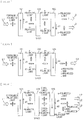
- FIG. 1 illustrates an example of a schematic configuration of an imaging apparatus according to an embodiment of the present disclosure.
- the imaging apparatus 1 includes, for example, an imaging optical system 10 , a lens driving unit 20 , an LPF driving unit 30 , an imaging element 40 , and an image processor 50 .
- the imaging apparatus 1 further includes, for example, a display panel 60 , a memory unit 70 , a controller 80 , and an operation unit 90 .
- the imaging optical system 10 includes, for example, a variable optical LPF (Low Pass Filter) 11 and a lens 12 .
- the lens 12 forms an optical subject image on the imaging element 40 .
- the lens 12 includes a plurality of lenses, and is driven by the lens driving unit 20 , thereby allowing at least one lens to be moved. Thus, the lens 12 allows for optical focus adjustment and zoom adjustment.
- the variable optical LPF 11 removes a high spatial frequency component included in light, and is driven by the LPF driving unit 30 to change a cut-off frequency fc that is one of lowpass characteristics.
- the imaging optical system 10 may be integrated with the imaging element 40 into one body, or may be configured separately from the imaging element 40 .
- variable optical LPF 11 in the imaging optical system 10 may be integrated with the imaging element 40 into one body, or may be configured separately from the imaging element 40 .
- a specific configuration of the variable optical LPF 11 and a method of modulating the cut-off frequency fc are described in detail later.
- the lens driving unit 20 drives at least one lens in the lens 12 for optical zoom magnification, focus adjustment, and the like in accordance with an instruction from the controller 80 .
- the LPF driving unit 30 performs control to change the lowpass characteristic (the cut-off frequency fc) of the variable optical LPF 11 in accordance with an instruction from the controller 80 , thereby adjusting an effect of the variable optical LPF 11 .
- the “effect of the variable optical LPF 11 ” indicates reduction in a component that is included in light and has a higher spatial frequency than a Nyquist frequency.
- the LPF driving unit 30 applies a predetermined voltage V (constant frequency) between electrodes of the variable optical LPF 11 to adjust the cut-off frequency fc of the variable optical LPF 11 .
- the imaging element 40 converts, into an electrical signal, a subject image formed on the light reception surface 40 A via the lens 12 and the variable optical LPF 11 to generate image data.
- the imaging element 40 includes, for example, a CCD (Charge Coupled Device) or a CMOS (Complementary Metal Oxide Semiconductor) image sensor.
- the imaging element 40 has the light reception surface 40 A on which a plurality of photoelectric converters 40 B are two-dimensionally arranged at predetermined intervals.
- the imaging element 40 further includes, for example, a color filter array 40 C on the light reception surface 40 A.
- FIG. 2 exemplifies a state in which the color filter array 40 C has a Bayer arrangement in which 2 ⁇ 2 arrays of R, G, G, and B are arranged in a matrix.
- the color filter array 40 C may have a different arrangement from the Bayer arrangement.
- the imaging element 40 generates image data on the basis of light incident via the variable optical LPF 11 .
- the imaging element 40 spatially samples light incident via the lens 12 and the variable optical LPF 11 to generate color image data.
- the image data includes color signals, per pixel, of respective colors included in the color filter array 40 C.
- the image processor 50 performs, on the image data generated by the imaging element, image processing such as white balance, demosaicing, gray-scale conversion, color conversion, and noise reduction.
- image processor 50 performs processing such as conversion of image data into display data suitable for display on the display panel 60 and conversion of image data into data suitable for recording on the memory unit 70 .
- Image processing in the image processor 50 is described in detail later.
- Display Panel 60 Memory Unit 70 , and Operation Unit 90
- the display panel 60 includes, for example, a liquid crystal panel.
- the display panel 60 displays display data inputted from the image processor 50 , and the like.
- the memory unit 70 is allowed to hold shot image data, various kinds of programs, etc.
- the memory unit 70 includes, for example, a nonvolatile memory.
- the memory unit 70 includes, for example, an EEPROM (Electrically Erasable Programmable Read-Only Memory), a flash memory, a resistive random access memory, etc.
- the memory unit 70 may be an external memory that is attachable to and detachable from the imaging apparatus 1 .
- the memory unit 70 holds, for example, various kinds of data generated by the image processor 50 and various kinds of data inputted from the operation unit 90 , as illustrated in FIG. 3 .
- FIG. 3 illustrates an example of data stored in the memory unit 70 .
- Examples of the data stored in the memory unit 70 include image data 71 , saturation data 72 , evaluation data 73 , and a set value 74 , as illustrated in FIG. 3 .
- the image data 71 , the saturation data 72 , the evaluation data 73 , and the set value 74 are described in detail later.
- the operation unit 90 receives an instruction from a user, and includes, for example, an operation button, a shutter button, an operation dial, a keyboard, a touch panel, etc.
- the controller 80 is a processor that controls the lens driving unit 20 , the LPF driving unit 30 , the imaging element 40 , the image processor 50 , the display panel 60 , and the memory unit 70 .
- the controller 80 controls the lens driving unit 20 to perform optical zoom magnification, focus adjustment, etc. of the lens 12 .
- the controller 80 controls the LPF driving unit 30 to adjust the effect (the cut-off frequency fc) of the variable optical LPF 11 .
- the controller 80 further drives the imaging element 40 to cause the imaging element 40 to generate image data and output the generated image data to the image processor 50 .
- the controller 80 controls the image processor 50 to cause the image processor 50 to perform the above-described image processing and output various kinds of data obtained as a result of the above-described image processing to the memory unit 70 and the display panel 60 .
- the controller 80 controls the lens driving unit 20 , the LPF driving unit 30 , the imaging element 40 , the image processor 50 , and the display panel 60 in accordance with various kinds of data inputted from the operation unit 90 , and stores various kinds of data inputted from the operation unit 90 in the memory unit 70 .
- FIG. 4 illustrates an example of a schematic configuration of the variable optical LPF 11 .
- the variable optical LPF 11 removes a high spatial frequency component included in light.
- the variable optical LPF 11 is driven by the LPF driving unit 30 to change the effect (the cut-off frequency fc) of the variable optical LPF 11 .
- the variable optical LPF 11 changes the cut-off frequency fc by, for example, a peak value modulation method. It is to be noted that the peak value modulation method is described in detail later.
- the variable optical LPF 11 includes a pair of birefringent plates 111 and 115 each having birefringence and a liquid crystal layer 113 disposed between the pair of birefringent plates 111 and 115 .
- the variable optical LPF 11 further includes electrodes 112 and 114 that apply an electric field to the liquid crystal layer 113 .
- the variable optical LPF 11 may include, for example, an alignment film that regulates alignment of the liquid crystal layer 113 .
- the electrodes 112 and 114 faces each other with the liquid crystal layer 113 in between.
- Each of the electrodes 112 and 114 includes one sheet electrode. It is to be noted that one or both of the electrode 112 and the electrode 114 may include a plurality of partial electrodes.
- the electrodes 112 and 114 each are a light-transmissive conductive film including ITO (Indium Tin Oxide), etc.
- the electrodes 112 and 114 each may be an inorganic conductive film having light transmittance, an organic conductive film having light transmittance, or a metal oxide film having light transmittance.
- the birefringent plate 111 is disposed on a light incident side of the variable optical LPF 11 , and an outside surface of the birefringent plate 111 serves as a light incident surface 110 A.
- the incident light L 1 is light entering the light incident surface 110 A from a subject side.
- the birefringent plate 111 is disposed to allow an optical axis of the incident light L 1 to be parallel to a normal to the birefringent plate 111 (or the light incident surface 110 A), for example.
- the birefringent plate 115 is disposed on a light exit side of the variable optical LPF 11 , and an outside surface of the birefringent plate 115 serves as a light exit surface 110 B. Transmitted light L 2 from the variable optical LPF 11 is light outputted from the light exit surface 110 B to outside.
- the birefringent plate 111 , the electrode 112 , the liquid crystal layer 113 , the electrode 114 , and the birefringent plate 115 are stacked in this order from the light incident side.
- the birefringent plates 111 and 115 each have birefringence, and have a uniaxial crystal structure.
- the birefringent plates 111 and 115 each have a function of performing ps separation on circularly polarized light with use of birefringence.
- the birefringent plates 111 and 115 each include, for example, quartz crystal, calcite, or lithium niobate.
- birefringent plates 111 and 115 separation directions of an image are oriented opposite to each other.
- An optical axis AX 1 of the birefringent plate 111 and an optical axis AX 2 of the birefringent plate 115 intersect with each other in a plane parallel to the normal to the light incident surface 10 A.
- An angle formed by the optical axis AX 1 and the optical axis AX 2 is, for example, 90°. Further, the optical axes AX 1 and AX 2 obliquely intersect with the normal to the light incident surface 10 A.
- An angle formed by the optical axis AX 1 and the normal to the light incident surface 110 A is, for example, smaller than 90° in a counterclockwise direction with reference to the normal to the light incident surface 110 A, and is, for example, 45°.
- FIG. 5 illustrates an example of a polarization conversion efficiency curve (V-T curve) of the liquid crystal layer 113 .
- a horizontal axis indicates the voltage V (the constant frequency) applied between the electrodes 112 and 114 .
- a vertical axis indicates polarization conversion efficiency T.
- the polarization conversion efficiency T is obtained through multiplying, by 100, a value that is obtained through dividing a phase difference applied to linearly polarized light by 90°.
- the polarization conversion efficiency T being 0% indicates that no phase difference is applied to the linearly polarized light, and indicates, for example, that the linearly polarized light passes through a medium without changing a polarization direction thereof.
- the polarization conversion efficiency T being 100% indicates that a phase difference of 90° is applied to the linearly polarized light, and indicates, for example, that p-polarized light is converted into s-polarized light or s-polarized light is converted into p-polarized light and then the s-polarized light or the p-polarized light passes through a medium.
- the polarization conversion efficiency T being 50% indicates that a phase difference of 45° is applied to the linearly polarized light, and indicates, for example, that p-polarized light or s-polarized light is converted into circularly polarized light and then the circularly polarized light passes through a medium.
- the liquid crystal layer 113 controls polarized light on the basis of an electric field generated by a voltage between the electrodes 112 and 114 .
- the polarization conversion efficiency T becomes T 2 upon application of a voltage V 1 between the electrodes 112 and 114
- the polarization conversion efficiency T becomes T 1 upon application of a voltage V 2 (V 1 ⁇ V 2 ) between the electrodes 112 and 114 .
- T 2 is 100%
- T 1 is 0%.
- the polarization conversion efficiency T becomes T 3 upon application of a voltage V 3 (V 1 ⁇ V 3 ⁇ V 2 ) between the electrodes 112 and 114 .
- T 3 is a value larger than 0% and smaller than 100%.
- the voltage V 3 is a voltage in a case where T 3 is 50% is illustrated as an example.
- the voltage V 1 is a voltage equal to or smaller than a voltage at a falling position of the polarization conversion efficiency curve, and specifically indicates a voltage in a section in which the polarization conversion efficiency is saturated around a maximum value of the polarization conversion efficiency curve.
- the voltage V 2 is a voltage equal to or larger than a voltage at a rising position of the polarization conversion efficiency curve, and specifically indicates a voltage in a section in which the polarization conversion efficiency is saturated around a minimum value of the polarization conversion efficiency curve.
- the voltage V 3 is a voltage (an intermediate voltage) between the voltage at the falling position of the polarization conversion efficiency curve and the voltage at the rising position of the polarization conversion efficiency curve.
- the liquid crystal layer 113 controls polarization.
- a liquid crystal having the above-described polarization conversion efficiency curve may include a twisted nematic (TN) liquid crystal.
- the TN liquid crystal includes a chiral nematic liquid crystal, and has optical rotary power that rotates a polarization direction of passing light along rotation of the nematic liquid crystal.
- FIG. 6A , FIG. 6B , and FIG. 6C each illustrate an example of workings of the variable optical LPF 11 .
- the voltage V between the electrodes 112 and 114 is the voltage V 1 .
- the voltage V between the electrodes 112 and 114 is the voltage V 2 .
- the voltage V between the electrodes 112 and 114 is the voltage V 3 .
- the incident light L 1 that is circularly polarized light enters the birefringent plate 111 , and thereafter, the incident light L 1 is separated into p-polarized light and s-polarized light by a separation width d 1 by birefringence of the birefringent plate 111 .
- a polarized component oscillating perpendicular to the optical axis AX 1 of the birefringent plate 111 is an s-polarized component included in the incident light L 1
- the separated s-polarized light travels in straight lines in the birefringent plate 111 without being influenced by birefringence and is outputted from a back surface of the birefringent plate 111 .
- a p-polarized component included in the incident light L 1 oscillates in a direction orthogonal to an oscillating direction of the s-polarized light.
- the p-polarized light obliquely travels in the birefringent plate 111 under an influence of birefringence, and is refracted at a position shifted by the separation width d 1 of the back surface of the birefringent plate 111 , and then outputted from the back surface of the birefringent plate 111 .
- the birefringent plate 111 separates the incident light L 1 into p-polarized transmitted light L 2 and s-polarized transmitted light L 2 by the separation width d 1 .
- the p-polarized light separated by the birefringent plate 111 enters the liquid crystal layer 113 of which polarization conversion efficiency is T 2 , and thereafter, the p-polarized light is converted into s-polarized light, and travels in straight lines in the liquid crystal layer 113 and is outputted from the back surface of the liquid crystal layer 113 .
- the s-polarized light separated by the birefringent plate 111 enters the liquid crystal layer 113 of which polarization conversion efficiency is T 2 , and thereafter, the s-polarized light is converted into p-polarized light, and travels in straight lines in the liquid crystal layer 113 and is outputted from the back surface of the liquid crystal layer 113 .
- the liquid crystal layer 113 performs ps conversion on the p-polarized light and the s-polarized light separated by the birefringent plate 111 , while keeping the separation width constant.
- a polarized component oscillating perpendicular to the optical axis AX 2 of the birefringent plate 115 is s-polarized light
- the s-polarized light travels in straight lines in the birefringent plate 115 without being influenced by birefringence and is outputted from the back surface of the birefringent plate 115 .
- the p-polarized light oscillates in a direction orthogonal to the oscillating direction of the s-polarized light.
- the p-polarized light obliquely travels in the birefringent plate 115 in a direction opposite to the separation direction of the image in the birefringent plate 111 .
- the p-polarized light is refracted at a position shifted by a separation width d 2 of the back surface of the birefringent plate 115 and is outputted from the back surface of the birefringent plate 115 .
- the birefringent plate 115 separates the s-polarized light and the p-polarized light that have passed through the liquid crystal layer 113 into s-polarized transmitted light L 2 and p-polarized transmitted light L 2 by a separation width (d 1 +d 2 ).
- the workings with respect to the incident light L 1 of the birefringent plate 111 are the same as described above. Hence, workings of each of the liquid crystal layer 113 and the birefringent plate 115 are described below.
- the p-polarized light and the s-polarized light separated by the birefringent plate 111 enter the liquid crystal layer 113 of which polarization conversion efficiency is T 1 , and thereafter, the p-polarized light and the s-polarized light travel in straight lines in the liquid crystal layer 113 without being subjected to polarization conversion by the liquid crystal layer 113 , and are outputted from the back surface of the liquid crystal layer 113 . Accordingly, the liquid crystal layer 113 has no optical workings with respect to the p-polarized light and the s-polarized light separated by the birefringent plate 111 .
- a polarized component oscillating perpendicular to the optical axis AX 2 of the birefringent plate 115 is the s-polarized light
- the s-polarized light travels in straight lines in the birefringent plate 115 without being influenced by birefringence and is outputted from the back surface of the birefringent plate 115 .
- the p-polarized light oscillates in a direction orthogonal to the oscillating direction of the s-polarized light. Hence, under the influence of birefringence, the p-polarized light obliquely travels in the birefringent plate 115 in a direction opposite to the separation direction of the image in the birefringent plate 111 . Further, the p-polarized light is refracted at a position shifted by the separation width d 2 of the back surface of the birefringent plate 115 and is outputted from the back surface of the birefringent plate 115 .
- the birefringent plate 115 separates the s-polarized light and the p-polarized light that have passed through the liquid crystal layer 113 into the s-polarized transmitted light L 2 and the p-polarized transmitted light L 2 by a separation width (
- d 1 d 2
- the s-polarized transmitted light L 2 and the p-polarized transmitted light L 2 are outputted from a mutually same position of the back surface of the birefringent plate 115 .
- the birefringent plate 115 combines the s-polarized light and the p-polarized light that have passed through the liquid crystal layer 113 to generate combined light.
- the workings with respect to the incident light L 1 of the birefringent plate 111 are the same as described above. Hence, the workings of each of the liquid crystal layer 113 and the birefringent plate 115 are described below.
- the circularly polarized light outputted from the liquid crystal layer 113 enters the birefringent plate 115 , and thereafter, the circularly polarized light is separated into p-polarized light and s-polarized light by the separation width d 2 by birefringence of the birefringent plate 115 .
- a polarized component oscillating perpendicular to the optical axis AX 2 of the birefringent plate 115 is s-polarized light
- the s-polarized light travels in straight lines in the birefringent plate 115 without being influenced by birefringence and is outputted from the back surface of the birefringent plate 115 .
- the p-polarized light oscillates in a direction orthogonal to the oscillating direction of the s-polarized light.
- the p-polarized light obliquely travels in the birefringent plate 115 in a direction opposite to the separation direction of the image in the birefringent plate 111 .
- the p-polarized light is refracted at a position shifted by the separation width d 2 of the back surface of the birefringent plate 115 and is outputted from the back surface of the birefringent plate 115 .
- the birefringent plate 115 respectively separates the circularly polarized light into which the p-polarized light is converted by the liquid crystal layer 113 and the circularly polarized light into which the s-polarized light is converted by the liquid crystal layer 113 , into the s-polarized transmitted light L 2 and the p-polarized transmitted light L 2 by the separation width d 2 .
- the p-polarized light that is separated from the circularly polarized light into which the p-polarized light is converted by the liquid crystal layer 113 and the s-polarized light that is separated from the circularly polarized light into which the s-polarized light is converted by the liquid crystal layer 113 are outputted from a mutually same position of the back surface of the birefringent plate 115 .
- the transmitted light L 2 that is circularly polarized light is outputted from the back surface of the birefringent plate 115 .
- the birefringent plate 115 separates two beams of circularly polarized light outputted from the liquid crystal layer 113 into the p-polarized transmitted light L 2 and the s-polarized transmitted light L 2 by the separation width (d 2 +d 2 ), and combines the once-separated p-polarized light and the once-separated s-polarized light at a position between the p-polarized transmitted light L 2 and the s-polarized transmitted light L 2 to generate combined light.
- variable optical LPF 11 generates one peak p1 in the point image intensity distribution of the transmitted light of the variable optical LPF 11 .
- the peak p1 is formed by one beam of transmitted light L 2 outputted from the birefringent plate 115 .
- the variable optical LPF 11 generates two peaks p2 and p3 in the point image intensity distribution of the transmitted light of the variable optical LPF 11 .
- the two peaks p2 and p3 are formed by two beams of transmitted light L 2 outputted from the birefringent plate 115 .
- the three peaks p1, p2, and p3 are formed by three beams of transmitted light L 2 outputted from the birefringent plate 115 .
- the variable optical LPF 11 In a case where the voltage V 3 is applied between the electrodes 112 and 114 and d 1 ⁇ d 2 is established, the variable optical LPF 11 generates four peaks p1, p2, p3, and p4 in the point image intensity distribution of the transmitted light of the variable optical LPF 11 .
- the four peaks p1, p2, p3, and p4 are formed by four beams of transmitted light L 2 outputted from the birefringent plate 115 .
- variable optical LPF 11 In a case where the voltage V 3 is applied between the electrodes 112 and 114 , the variable optical LPF 11 generates the three peaks p1 to p3 or the four peaks p1 to p4 in the point image intensity distribution of the transmitted light of the variable optical LPF 11 .
- values of the above-described three peaks p1 to p3 or values of the above-described four peaks p1 to p4 are changed.
- the variable optical LPF 11 in a case where the magnitude of the voltage V 3 applied between the electrodes 112 and 114 is changed, the point image intensity distribution of the transmitted light is changed.
- variable optical LPF 11 changes the magnitude of the voltage V applied between the electrodes 112 and 114 to change the point image intensity distribution of the transmitted light.
- peak values (peak heights) of the above-described three peaks p1 to p3 and peak values (peak heights) of the above-described four peaks p1 to p4 are changed with the magnitude of the voltage V applied between the electrodes 112 and 114 .
- peak positions of the above-described three peaks p1 to p3 and peak positions of the above-described four peaks p1 to p4 are determined by the separation widths d 1 and d 2 .
- the separation widths d 1 and d 2 are fixed irrespective of the magnitude of the voltage V 3 applied between the electrodes 112 and 114 . Accordingly, the peak positions of the above-described three peaks p1 to p3 and the peak positions of the above-described four peaks p1 to p4 are fixed irrespective of the magnitude of the voltage V 3 applied between the electrodes 112 and 114 .
- FIG. 7 illustrates an example of an MTF (Modulation Transfer Function) in each of FIG. 6A . to FIG. 6C .
- a horizontal axis indicates a spatial frequency
- a vertical axis indicates standardized contrast.
- the variable optical LPF 11 has no light beam separation effect; therefore, the MTF in FIG. 6B is coincident with an MTF of a lens (for example, the lens 13 , or the like) provided in a preceding stage of the variable optical LPF 11 .
- a distance between peaks is larger than a distance between peaks in FIG. 6C , and the light beam separation effect is maximum. Accordingly, a cut-off frequency fc1 of the MTF in FIG. 6A is smaller than a cut-off frequency fc2 of the MTF in FIG. 6C .
- the separation width is equal to the separation width in FIG. 6A , but the number of peaks is larger than the number of peaks in FIG. 6A , and the distance between peaks is narrower than the distance between peaks in FIG. 6A . Accordingly, in FIG. 6C , the light beam separation effect is weaker than the light beam separation effect in FIG. 6A ; therefore, the cut-off frequency fc2 of the MTF in FIG. 6C is larger than the cut-off frequency fc1 of the MTF in FIG. 6A . The cut-off frequency fc2 of the MTF in FIG.
- variable optical LPF 11 changes the magnitude of the voltage V applied between the electrodes 112 and 114 to set the cut-off frequency fc to any value equal to or larger than a cut-off frequency at which the light beam separation effect is maximum.
- the memory unit 70 holds the image data 71 , the saturation data 72 , the evaluation data 73 , and the set value 74 , as described above.
- the image data 71 includes a plurality of pieces of image data obtained by the imaging element 40 , and includes, for example, image data I 1 to be described later, a plurality of pieces of image data I 2 to be described later, image data I to be described later, etc.
- the image data I 1 is image data without false color or image data with less false color.
- the image data without false color or the image data with less false color is obtained, for example, in a case where the effect of the variable optical LPF 11 is maximum or substantially maximum. In other words, the image data without false color or the image data with less false color is obtained, for example, in a case where the cut-off frequency fc of the variable optical LPF 11 is minimum or substantially minimum.
- the plurality of pieces of image data I 2 are image data obtained in a case where a set value different from a set value used to obtain the image data I 1 is set to the variable optical LPF 11 .
- the image data I is image data obtained by the imaging element 40 in a state in which an appropriate set value (the set value 74 ) is set to the variable optical LPF 11 .
- the set value 74 is a set value of the variable optical LPF 11 suitable for a purpose of a user, and is a set value set to the variable optical LPF 11 to obtain the image data I.
- the set value 74 is obtained by execution of image processing in the image processor 50 .
- the saturation data 72 is data related to saturation obtained from the image data I 1 .
- the saturation data 72 is, for example, two-dimensional data corresponding to each dot of a predetermined unit of the image data I 1 .
- the evaluation data 73 is data for evaluation of resolution and false color.
- the resolution is an indication representing finest distinguishable detail. “Resolution being high” indicates that a shot image has definition with which finer detail is distinguishable. “Resolution being low” indicates that the shot image does not have definition and has blurring. “Resolution being deteriorated” indicates that the shot image loses initial definition and has severer blurring than an initial shot image. In a case where the shot image having a high spatial frequency passes through a lowpass filter, a high-frequency component of the shot image is reduced to reduce (deteriorate) resolution of the shot image. In other words, deterioration in resolution corresponds to reduction in spatial frequency. Incidentally, false color is a phenomenon in which a color that is not an original color appears in an image. Respective colors are spatially sampled.
- the shot image includes a high-frequency component having a frequency exceeding the Nyquist frequency
- this phenomenon occurs by aliasing (folding of the high-frequency component to a low frequency region).
- the high-frequency component having a frequency exceeding the Nyquist frequency included in the shot image is reduced by the lowpass filter, thereby suppressing generation of false color in the shot image while reducing (deteriorating) resolution of the shot image.
- the evaluation data 73 is derived on the basis of the image data I 1 and the plurality pieces of image data I 2 . Specifically, the evaluation data 73 is derived on the basis of the image data I 1 , the plurality of pieces of image data I 2 , and the saturation data 33 .
- D is evaluation data about resolution and false color.
- f(I 1 , I 2 ) is a mathematical function that derives evaluation data (evaluation data D 1 ) about change (deterioration) in resolution between two pieces of image data I 1 and I 2 obtained by the imaging element 40 , and means that the resolution is reduced with an increase in a value of the evaluation data D 1 .
- the evaluation data D 1 corresponds to a specific example of “first evaluation data” of the present disclosure.
- f(I 1 , I 2 ) is a mathematical function that derives the evaluation data D 1 on the basis of spatial frequencies of two pieces of image data I 1 and I 2 .
- f(I 1 , I 2 ) is a mathematical function that derives the evaluation data D 1 on the basis of, for example, a difference between a frequency spectrum of the image data I 1 and a frequency spectrum of the image data I 2 .
- f(I 1 , I 2 ) is a mathematical function that derives the evaluation data D 1 on the basis of power extracted at a frequency at which the effect of the variable optical LPF 11 is maximum. The power is extracted from the difference between the frequency spectrum of the image data I 1 and the frequency spectrum of the image data I 2 .
- the evaluation data D 1 is derived from the first term on the right-hand side of the equation (1).
- C is the saturation data 72 .
- ⁇ C ⁇ G(I 1 , I 2 ) is a mathematical function that derives evaluation data (evaluation data D 2 ) about change in false color between two pieces of image data and I 2 on the basis of gray-scale data of the two pieces of image data I 1 and I 2 , and means that false color is generated in a wider range with an increase in the value of ⁇ C ⁇ G(I 1 , I 2 ).
- the evaluation data D 2 corresponds to a specific example of “second evaluation data” of the present disclosure.
- ⁇ C ⁇ G(I 1 , I 2 ) is a mathematical function that derives the evaluation data D 2 on the basis of, for example, a difference between the gray-scale data of the image data I 1 and the gray-scale data of the image data I 2 .
- ⁇ C ⁇ G(I 1 , I 2 ) is a mathematical function that derives the evaluation data D 2 on the basis of, for example, the difference between the gray-scale data of the image data I 1 and the gray-scale data of the image data I 2 , and C (the saturation data 72 ) obtained from the image data I 1 .
- ⁇ C ⁇ G(I 1 , I 2 ) is, for example, a mathematical function that derives, as the evaluation data D 2 , a total sum obtained by multiplying the difference between the gray-scale data of the image data I 1 and the gray-scale data of the image data I 2 by C.
- the evaluation data D 2 in consideration of saturation of a subject is derived from the second term on the right-hand side of the equation (1).
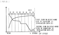
- FIG. 8 illustrates an example of the evaluation data D 1 obtained from the first term on the right-hand side of the equation (1) and the evaluation data D 2 obtained from the second term on the right-hand side of the equation (1) in graph. It is seen that in the evaluation data D 1 obtained from the first term on the right-hand side of the equation (1), at the beginning, resolution is abruptly worsened with an increase in the effect of the variable optical LPF 11 , and later on, change in resolution becomes gradually gentle. It is seen that in the evaluation data D 2 obtained from the second term on the right-hand side of the equation (1), a range of false color is gradually reduced with an increase in the effect of the variable optical LPF 11 .
- FIG. 9 illustrates an example of functional blocks of the image processor 50 .
- the image processor 50 performs predetermined processing on image data outputted from the imaging element 40 .
- the image processor 50 sets the set value 74 of the effect (or the lowpass characteristics) of the variable optical LPF 11 on the basis of change in resolution and change in false color in a plurality of pieces of image data taken in accordance with changing of the effect (or the lowpass characteristics) of the variable optical LPF 11 , for example.
- Examples of the lowpass characteristics include the cut-off frequency fc.
- the image processor 50 includes, for example, a preprocessing circuit 51 , an image processing circuit 52 , a display processing circuit 53 , a compression decompression circuit 54 , and a memory control circuit 55 .
- the preprocessing circuit 51 performs optical correction processing such as shading correction on the image data outputted from the imaging element 40 .
- the image processing circuit 52 performs various kinds of processing to be described later on the corrected image data outputted from the preprocessing circuit 51 .
- the image processing circuit 52 further outputs, for example, the image data obtained from the imaging element 40 to the display processing circuit 53 .
- the image processing circuit 52 further outputs, for example, the image data obtained from the imaging element 40 to the compression decompression circuit 54 .
- the image processing circuit 52 is described in detail later.
- the display processing circuit 53 generates an image signal to be displayed on the display panel 60 , from the image data received from the image processing circuit 52 , and transmits the image signal to the display panel 60 .
- the compression decompression circuit 54 performs, for example, compression encoding processing with a still-image encoding method such as JPEG (Joint Photographic Experts Group), on image data of a still image received from the image processing circuit 52 .
- the compression decompression circuit 54 performs, for example, compression encoding processing with a moving-image encoding method such as MPEG (Moving Picture Experts Group), on image data of a moving image received from the image processing circuit 52 .
- the memory control circuit 55 controls data writing to and reading from the memory unit 70 .
- FIG. 10 illustrates an example of the imaging procedure in the imaging apparatus 1 .
- the controller 80 performs operation preparation (step S 101 ).
- the operation preparation indicates preparation necessary for outputting of the image data I from the imaging element 40 , and indicates, for example, setting a condition of AF (autofocus), and the like.
- the controller 80 detects a preparation instruction from a user (such as pressing a shutter button halfway)
- the controller 80 instructs the lens driving unit 20 and the LPF driving unit 30 to perform operation preparation such as AF.
- the lens driving unit 20 performs operation preparation on the lens 12 before outputting of the image data I 1 in accordance with such an instruction from the controller 80 .
- the lens driving unit 20 sets, for example, a focus condition, etc.
- the controller 80 causes the lens driving unit 20 to execute operation preparation such as AF while causing the variable optical LPF 11 not to optically operate.
- the LPF driving unit 30 performs operation preparation on the variable optical LPF 11 before outputting of the image data I 1 in accordance with such an instruction from the controller 80 .
- the LPF driving unit 30 applies, for example, the voltage V 2 between the electrodes 112 and 114 .
- the polarization conversion efficiency T of the variable optical LPF 11 is T 1 .
- the controller 80 generates a change instruction for changing the effect of the variable optical LPF 11 by a pitch larger than a set minimum resolving power of the effect of the variable optical LPF 11 , and gives the change instruction to the LPF driving unit 30 .
- the controller 80 generates a change instruction for changing the cut-off frequency fc of the variable optical LPF 11 by a pitch larger than a set minimum resolving power of the cut-off frequency fc of the variable optical LPF 11 , and gives the change instruction to the LPF driving unit 30 .
- the LPF driving unit 30 changes, for example, the voltage V (the constant frequency) applied between the electrodes of the variable optical LPF 11 by a pitch larger than the set minimum resolving power to gradually change the cut-off frequency fc of the variable optical LPF 11 .
- the controller 80 generates an imaging instruction in synchronization with changing of the effect (the cut-off frequency fc) of the variable optical LPF 11 , and gives the imaging instruction to the imaging element 40 .
- the imaging element 40 performs imaging in synchronization with changing of the effect of the variable optical LPF 11 (changing of the cut-off frequency fc) in accordance with such an instruction from the controller 80 .
- the imaging element 40 generates a plurality of pieces of imaging data with mutually different effects (the cut-off frequencies fc) of the variable optical LPF 11 , and outputs the plurality of pieces of imaging data to the image processor 50 .
- the controller 80 instructs the LPF driving unit 30 to make the effect of the variable optical LPF 11 maximum or substantially maximum within a range in which the effect of the variable optical LPF 11 is changeable (step S 102 ).
- the controller 80 instructs the LPF driving unit 30 to make the cut-off frequency fc of the variable optical LPF 11 minimum or substantially minimum within a range in which the cut-off frequency fc is changeable.
- the LPF driving unit 30 makes the effect of the variable optical LPF 11 maximum or substantially maximum within the range in which the effect of the variable optical LPF 11 is changeable in accordance with such an instruction from the controller 80 .
- the LPF driving unit 30 makes the cut-off frequency fc of the variable optical LPF 11 minimum or substantially minimum within the range in which the cut-off frequency fc of the variable optical LPF 11 is changeable.
- the LPF driving unit 30 applies, for example, the voltage V 1 or a voltage having a slightly larger value than the voltage V 1 between the electrodes 112 and 114 .
- the polarization conversion efficiency T of the variable optical LPF 11 becomes T 2 (maximum) or a value close to T 2 .
- the controller 80 instructs the imaging element 40 to obtain the image data I 1 (step S 103 ). Specifically, the controller 80 instructs the imaging element 40 to obtain the imaging data I 1 while the effect of the variable optical LPF 11 is maximum or substantially maximum within the range in which the effect of the variable optical LPF 11 is changeable. In other words, the controller 80 instructs the imaging element 40 to obtain the image data I 1 while the cut-off frequency fc of the variable optical LPF 11 is minimum or substantially minimum within the range in which the cut-off frequency fc of the variable optical LPF 11 is changeable. By doing so, the imaging element 40 obtains the color image data I 1 through discretely sampling, on the light reception surface 40 A, light incident via the variable optical LPF 11 of which the effect is maximum or substantially maximum.
- the imaging element 40 obtains the color image data I 1 through discretely sampling, on the light reception surface 40 A, light incident via the variable optical LPF 11 of which the cut-off frequency fc is minimum or substantially minimum.
- the imaging element 40 obtains the color image data I 1 through discretely sampling, on the light reception surface 40 A, light incident via the variable optical LPF 11 of which the polarization conversion efficiency T is maximum or substantially maximum.
- the image data I 1 is image data generated by the imaging element 40 through driving the imaging element 40 in a case where the effect of the variable optical LPF 11 is maximum or substantially maximum within the range in which the effect of the variable optical LPF 11 is changeable.
- the image data I 1 is image data generated by the imaging element 40 through driving the imaging element 40 in a case where the cut-off frequency fc of the variable optical LPF 11 is minimum or substantially minimum within the range in which the cut-off frequency fc of the variable optical LPF 11 is changeable.
- the image data I 1 corresponds to a specific example of “first image data” of the present disclosure.
- the imaging element 40 outputs the obtained image data I 1 to the image processor 50 .
- the image processor 50 analyzes the obtained image data I 1 to derive data (the saturation data 33 ) related to saturation in the image data I 1 (step S 104 ).
- the controller 80 instructs the LPF driving unit 30 to change the effect of the variable optical LPF 11 (step S 105 ). Specifically, the controller 80 instructs the variable optical LPF 11 to cause the effect of the variable optical LPF 11 to become smaller than the previous effect of the variable optical LPF 11 . In other words, the controller 80 instructs the LPF driving unit 30 to cause the cut-off frequency fc of the variable optical LPF 11 to become larger than the previous cut-off frequency fc. By doing so, the LPF driving unit 30 causes the effect of the variable optical LPF 11 to become smaller than the previous effect of the variable optical LPF 11 in accordance with such an instruction from the controller 80 .
- the LPF driving unit 30 causes the cut-off frequency fc of the variable optical LPF 11 to become larger than the previous cut-off frequency fc of the variable optical LPF 11 .
- the LPF driving unit 30 applies, for example, a voltage larger than the previous voltage as the voltage V 3 between the electrodes 112 and 114 .
- the polarization conversion efficiency T of the variable optical LPF 11 has a magnitude between T 2 and T 1 and a value smaller than the previous value.
- the controller 80 instructs the imaging element 40 to obtain the image data I 2 (step S 106 ).
- the image data I 2 corresponds to a specific example of “second image data” of the present disclosure.
- the controller 80 instructs the imaging element 40 to obtain the image data I 2 in a case where a set value different from the set value used to obtain the image data I 1 is set to the variable optical LPF 11 .
- the imaging element 40 obtains the color image data I 2 through spatially sampling, on the light reception surface 40 A, light incident via the variable optical LPF 11 of which the effect is smaller than the previous effect of the variable optical LPF 11 .
- the imaging element 40 obtains the color image data I 2 through spatially sampling, on the light reception surface 40 A, light incident via the variable optical LPF 11 of which the cut-off frequency fc is larger than the previous cut-frequency fc of the variable optical LPF 11 .
- the imaging element 40 obtains the color image data I 2 through spatially sampling, on the light reception surface 40 A, light incident via the variable optical LPF 11 of which the polarization conversion efficiency T has a magnitude between T 2 and T 1 .
- the imaging element 40 outputs the obtained image data I 2 to the image processor 50 .
- the controller 80 instructs the image processor 50 to derive appropriate lowpass characteristics (the set value 74 ).
- the image processor 50 derives the appropriate lowpass characteristics (the set value 74 ) on the basis of change in resolution and change in false color in a plurality of pieces of image data (the image data I 1 and the image data I 2 ) obtained by the imaging element 40 .
- the image processor 50 derives two pieces of evaluation data D 1 and D 2 on the basis of the plurality of pieces of image data (the image data I 1 and the image data I 2 ) (step S 107 ).
- the image processor 50 derives the evaluation data D 1 about change in resolution on the basis of the plurality of pieces of image data (the image data I 1 and the image data I 2 ).
- the image processor 50 derives the evaluation data D 1 on the basis of, for example, a difference between the frequency spectrum of the image data I 1 and the frequency spectrum of the image data I 2 .
- the image processor 50 derives the evaluation data D 1 , for example, through applying the image data I 1 and the image data I 2 to the first term on the right-hand side of the equation (1).
- the image processor 50 derives the evaluation data D 2 about change in false color on the basis of gray-scale data of the plurality of pieces of image data (the image data I 1 and the image data I 2 ).
- the image processor 50 derives the evaluation data D 2 on the basis of, for example, a difference between the gray-scale data of the image data and the gray-scale data of the image data I 2 .
- the image processor 50 derives the evaluation data D 2 on the basis of, for example, the difference between gray-scale data of the image data I 1 and the gray-scale data of the image data I 2 , and the saturation data 33 obtained from the image data I 1 .
- the image processor 50 derives the evaluation data D 2 , for example, through applying the image data I 1 , the image data I 2 , and the saturation data 33 to the second term on the right-hand side of the equation (1).
- the image processor 50 determines appropriateness of the effect of the variable optical LPF 11 on the basis of two pieces of the evaluation data D 1 and D 2 obtained (step S 108 ). In other words, the image processor 50 determines whether or not the two pieces of the evaluation data D 1 and D 2 obtained satisfy a desired standard corresponding to a purpose.
- the “desired standard corresponding to the purpose” depends on a shooting mode, a subject, a scene, etc. For example, the image processor 50 determines whether or not a total value (the evaluation data D) of the two pieces of evaluation data D 1 and D 2 newly obtained this time is a minimum value in a region where the effect (the cut-off frequency fc) of the variable optical LPF 11 is controllable.
- the image processor 50 determines that the effect of the variable optical LPF 11 is appropriate, the image processor 50 adopts the lowpass characteristics of the variable optical LPF 11 at this time as the set value 74 . Specifically, in the case where the image processor 50 determines that the effect of the variable optical LPF 11 is appropriate, the image processor 50 adopts the set value of the variable optical LPF 11 at this time as the set value 74 .
- the image processor 50 stores the set value 74 in the memory unit 70 .
- the image processor 50 determines that the total value (the evaluation data D) of the two pieces of the evaluation data D 1 and D 2 newly obtained this time is the minimum value in the region where the effect of the variable optical LPF 11 is controllable, the image processor 50 adopts the set value of the variable optical LPF 11 at this time as the set value 74 .
- the image processor 50 determines that the effect of the variable optical LPF 11 is not appropriate, the image processor 50 returns to the step S 105 , and changes the effect (the cut-off frequency fc) of the variable optical LPF 11 , and sequentially executes the step S 106 and subsequent steps.
- the image processor 50 repeatedly executes the steps S 105 to S 108 to derive the set value 74 of the variable optical LPF 11 on the basis of two pieces of derived evaluation data D 1 and D 2 .
- the image processor 50 derives the set value 74 of the variable optical LPF 11 on the basis of the plurality of pieces of image data (the image data and the plurality of pieces of image data I 2 ) shot while changing lowpass characteristics (cut-off frequencies) in accordance with the preparation instruction from the user (for example, pressing the shutter button halfway).
- the image processor 50 provides, to the controller 80 , a notification that the set value 74 is obtained.
- the controller 80 In a case where the controller 80 detects the imaging instruction from the user (for example, pressing the shutter button) after the controller 80 receives, from the image processor 50 , the notification that the set value 74 is obtained, the controller 80 instructs the LPF driving unit 30 to set the variable optical LPF 11 to the set value 74 . Specifically, in a case where the controller 80 detects the imaging instruction from the user (for example, pressing the shutter button), the controller 80 reads the set value 74 from the memory unit 70 , and outputs the read set value 74 to the LPF driving unit 30 , and instructs the LPF driving unit 30 to set the variable optical LPF 11 to the set value 74 . By doing so, LPF driving unit 30 sets the variable optical LPF 11 to the set value 74 in accordance with the instruction from the controller 80 .
- the controller 80 further instructs the imaging element 40 to obtain the image data I.
- the imaging element 40 obtains the image data I in accordance with such an instruction from the controller 80 (step S 109 ).
- the imaging element 40 obtains the color image data I through discretely sampling, on the light reception surface 40 A, light incident via the variable optical LPF 11 that has been set to the set value 74 .
- the imaging element 40 outputs the obtained image data I to the image processor 50 .
- the image processor 50 performs predetermined processing on the image data I, and thereafter outputs the image data I having that has been subjected to the processing to the memory unit 70 and the display panel 60 .
- the memory unit 70 holds the image data I inputted from the image processor 50
- the display unit 60 displays the image data I inputted from the image processor 50 (step S 110 ).
- the above-described operation preparation may be performed by a manual operation by the user.
- steps may be executed again from the step of obtaining the image data I 1 .
- the above-described instruction from the user may be performed by a method other than “pressing the shutter button halfway”.
- the above-described instruction from the user may be performed through pressing a button (an operation button other than the shutter button) attached to a main body of the imaging apparatus 1 after setting the focus condition, etc. of the lens 13 .
- the above-described instruction from the user may be performed through turning an operation dial attached to the main body of the imaging apparatus 1 after setting the focus condition, etc. of the lens 13 .
- the “desired standard corresponding to the purpose” depends on the shooting mode, the subject, the scene, etc. Examples of the “desired standard corresponding to the purpose” is therefore described below.
- the controller 80 may set, as the set value 74 , the effect of the variable optical LPF 11 in a case where the evaluation data D 2 is smallest within the range ⁇ (indicated by a white circle in FIG. 8 ).
- the controller 80 may set, as the set value 74 , the cut-off frequency fc of the variable optical LPF 11 in the case where the evaluation data D 2 is smallest within the range ⁇ (indicated by the white circuit in FIG. 8 ). In such a case, it is possible to reduce deterioration in resolution without a large increase in false color.
- the second term (the evaluation data D 2 ) on the right-hand side of the equation (1) may serve as, for example, a stepwise profile depending on characteristics of the subject and the lens 13 , as illustrated in FIG. 11 .
- FIG. 11 illustrates an example of the evaluation data D 1 and D 2 .
- the controller 80 instructs the LPF driving unit 30 to divide the region where the effect (the cut-off frequency fc) of the variable optical LPF 11 is controllable into a plurality of regions R and sequentially change the effect of the variable optical LPF 11 to a value set for each of the divided regions R, as illustrated in FIG. 11 .
- the LPF driving unit 30 sequentially sets the effect (the cut-off frequency fc) of the variable optical LPF 11 to the value set for each of the regions R in accordance with such an instruction from the controller 80 .
- each of the regions R has a width larger than the set minimum resolving power of the effect (the cut-off frequency fc) of the variable optical LPF 11 .
- the LPF driving unit 30 sequentially changes the effect (the cut-off frequency fc) of the variable optical LPF 11 by a pitch larger than the set minimum resolving power of the effect (the cut-off frequency fc) of the variable optical LPF 11 .
- the controller 80 instructs the imaging element 40 to perform imaging in synchronization with setting of the effect (the cut-off frequency fc) of the variable optical LPF 11 .
- the imaging element 40 obtains the image data I 1 and the plurality of pieces of image data I 2 , and outputs the image data I 1 and the plurality of pieces of image data I 2 that are thus obtained to the image processor 50 .
- the image processor 50 derives two pieces of evaluation data D 1 and D 2 on the basis of the image data I 1 and the plurality of pieces of image data I 2 that are thus inputted.
- the image processor 50 may set the set value of the variable optical LPF 11 to a value at which false color starts increasing (for example, k in FIG. 11 ) in a region R (for example, a region R 1 ) where a total value (the evaluation data D) of the two pieces of evaluation data D 1 and D 2 is minimum.
- a region R for example, a region R 1
- a total value (the evaluation data D) of the two pieces of evaluation data D 1 and D 2 is minimum.
- the image processor 50 may set the set value 74 on the basis of change in false color in a face region included in a plurality of pieces of image data (the image data I 1 and the image data I 2 ).
- FIG. 12 illustrates an example of an imaging procedure in a case where a person whose face is detected has hair.
- the image processor 50 may execute face detection on the image data I 1 upon obtaining the image data I 1 from the imaging element 40 (step S 111 in FIG. 12 ). Moreover, in a case where the face is detected as a result of execution of the face detection on the image data I 1 in the step S 111 , the image processor 50 may detect whether or not the person whose face is detected has hair (step S 112 in FIG. 12 ).
- the image processor 50 may perform, for example, threshold processing on the evaluation data D 2 .
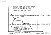
- the image processor 50 may determine, as the set value 74 , a set value that makes the effect of the variable optical LPF 11 weakest within a range in which the evaluation data D 2 is lower than a predetermined threshold value Th 1 ( FIG. 13 ).
- FIG. 13 illustrates an example of the evaluation data D 1 and D 2 together with various threshold values.
- the predetermined threshold value Th 1 is a threshold value for face detection, and is, for example, a value suitable to remove false color generated in hair of a human that is the subject.
- the image processor 50 may perform threshold processing not only on the evaluation data D 2 but also on the evaluation data D 1 , for example.
- the controller 80 may determine, as the set value 74 , a set value that makes the effect of the variable optical LPF 11 weakest within a range in which the evaluation data D 2 is lower than the predetermined threshold value Th 1 and within a range in which the evaluation data D 1 is lower than a predetermined threshold value Th 2 ( FIG. 13 ).
- the image processor 50 may determine the set value 74 by a method similar to the above-described method. In the case where the person whose face is detected has hair, the image processor 50 may determine the set value 74 in this manner.
- FIG. 14 illustrates an example of an imaging procedure in a macro shooting mode.
- the shooting mode is the macro shooting mode
- the user is often intended to shoot an object in close proximity to the object.
- generation of false color in the product to be shot is often unacceptable.
- the user himself actually confirm the presence or absence of false color, and then determine the set value 74 .
- the image processor 50 preferably sets, as the set value 74 , the effect (the cut-off frequency fc) of the variable optical LPF 11 in taking one piece of image data I 2 selected by the user from the plurality of pieces of image data I 2 .
- the image processor 50 performs the following processing upon detection of an imaging instruction from the user (for example, pressing the shutter button).
- the image processor 50 sequentially executes the steps S 102 to S 107 , and thereafter, the image processor 50 determines, for example, whether or not the evaluation data D 2 is smaller than a predetermined threshold value Th 3 in step S 108 .
- the predetermined threshold value Th 3 is a threshold value for the macro shooting mode, and is, for example, a value suitable to remove false color generated in an object that is a subject in the macro shooting mode.
- the image processor 50 obtains, as an appropriate value candidate 35 a , the set value of the variable optical LPF 11 corresponding to the evaluation data D 2 at this time (step S 113 in FIG. 14 ), and further stores the image data I 2 corresponding to the appropriate value candidate 35 a together with the appropriate value candidate 35 a in the memory unit 70 .
- the image processor 50 returns to the step S 105 .
- the image processor 50 may perform threshold processing, for example, not only on the evaluation data D 2 but also on the evaluation data D 1 .
- the image processor 50 may determine whether or not the evaluation data D 2 is lower than the predetermined threshold value Th 3 and whether or not the evaluation data D 1 is lower than a predetermined threshold value Th 4 ( FIG. 13 ).
- the image processor 50 may obtain the set value of the variable optical LPF 11 corresponding to the evaluation data D 2 as the appropriate value candidate 35 a .
- the image processor 50 may return to the step S 105 .
- the image processor 50 determines whether or not the changing of the effect of the variable optical LPF 11 is completed (step S 114 in FIG. 14 ).
- the image processor 50 repeatedly executes the steps S 105 to S 108 and S 113 until the changing of the effect of the variable optical LPF 11 is completed.
- the image processor 50 obtains a value corresponding to the evaluation data D 2 at this time as the appropriate value candidate 35 a .
- the image processor 50 requests the user to select one piece of image data I 2 from the plurality of pieces of image data I 2 corresponding to respective appropriate value candidates 35 a.
- the image processor 50 outputs, to the display unit 60 , one piece of image data I 2 selected from the plurality of pieces of image data I 2 corresponding to the respective appropriate value candidates 35 a .
- the display unit 60 displays the image data I 2 inputted from the image processor 50 (step S 115 in FIG. 14 ).
- the image processor 50 sequentially outputs the plurality of pieces of image data I 2 corresponding to the respective appropriate value candidates 35 a to the display unit 60 .
- the image processor 50 outputs the plurality of pieces of image data I 2 to the display unit 60 so as to change from the image data I 2 displayed on the display unit 60 to another image data I 2 .
- the display unit 60 changes the image data I 2 to be displayed every time the image data I 2 is inputted from the image processor 50 .
- the image processor 50 may output, to the display unit 60 , for example, a numerical value (for example, an area of a false color generation region in terms of pixel) and a histogram together with the image data I 2 .
- a numerical value for example, an area of a false color generation region in terms of pixel
- a histogram together with the image data I 2 .
- the display unit 60 displays the numerical value and the histogram inputted from the image processor 50 .
- the histogram may be, for example, a representation of each region with a shade corresponding to the number of pixels in which false color is generated, where a vertical axis and a horizontal axis indicate saturation (for example, Cb and Cr on YCbCr space), as illustrated in FIG. 15 .
- the image processor 50 determines, as the set value 74 , the appropriate value candidate 35 a corresponding to the image data I 2 displayed on the display unit 60 upon such detection.
- the image processor 50 causes the user to select appropriate image data I 2 (that is, an appropriate value as the variable optical LPF 11 ) (step S 116 in FIG. 14 ).
- the image processor 50 may determine, as the set value 74 , a set value that makes the effect of the variable optical LPF 11 weakest (a set value that makes the cut-off frequency fc largest) within the range in which the evaluation data D 2 is lower than the predetermined threshold value Th 3 .
- the image processor 50 may perform the threshold processing, for example, not only on the evaluation data D 2 but also on the evaluation data D 1 .
- the image processor 50 may determine, as the set value 74 , a set value that makes the effect of the variable optical LPF 11 weakest (a set value that makes the cut-off frequency fc largest) within the range in which the evaluation data D 1 is lower than the predetermined threshold value Th 3 and within the range in which the evaluation data D 1 is lower than the predetermined threshold value Th 4 .
- the image processor 50 may execute detection of the false color generation position after the step S 101 is performed. It is considered that in a case where false color is generated in a very large region of an entire screen or in a case where false color is generated at a center of the screen, if the false color remains, there is a possibility that the remaining false color is conspicuous. Moreover, it is considered that in a case where false color is present at four corners of the screen, completely eliminating the false color may unnecessarily cause deterioration in resolution.
- the image processor 50 preferably adjusts the effect of the variable optical LPF 11 in accordance with the false color generation position. Specifically, the image processor 50 preferably sets the set value 74 on the basis of change in resolution and change in false color in a plurality of pieces of image data I 1 and I 3 , and a position of false color included in the plurality of pieces of image data I 1 and I 3 .
- FIG. 16 illustrates an example of an imaging procedure in the false color processing mode.
- the image processor 50 executes detection of the false color generation position after executing the steps S 101 to S 104 .
- the controller 80 makes the effect of the variable optical LPF 11 minimum or substantially minimum (step S 117 ).
- the controller 80 instructs the LPF driving unit 30 to make the effect of the variable optical LPF 11 minimum or substantially minimum (to make the cut-off frequency fc maximum or substantially maximum).
- the LPF driving unit 30 makes the effect of the variable optical LPF 11 minimum or substantially minimum in accordance with such an instruction from the controller 80 .
- the LPF driving unit 30 makes the cut-off frequency fc maximum or substantially maximum in accordance with the instruction from the controller 80 .
- the LPF driving unit 30 applies, for example, the voltage V 2 or a voltage slightly smaller than the voltage V 2 between the electrodes 112 and 114 .
- the polarization conversion efficiency T of the variable optical LPF 11 becomes T 1 (minimum) or substantially T 1 .
- the image processor 50 obtains the image data I 3 in a case where the effect of the variable optical LPF 11 is minimum or substantially minimum (step S 118 ).
- the controller 80 instructs the imaging element 40 to perform imaging in the case where the effect of the variable optical LPF 11 is minimum or substantially minimum.
- the controller 80 instructs the imaging element 40 to perform imaging in a case where the cut-off frequency fc is maximum or substantially maximum.
- the imaging element 40 obtains the color image data I 3 through discretely sampling, on the light reception surface 40 A, light incident via the variable optical LPF 11 of which the effect is minimum or substantially minimum.
- the imaging element 40 obtains the color image data I 3 through discretely sampling, on the light reception surface 40 A, light incident via the variable optical LPF 11 of which the cut-off frequency fc is maximum or substantially maximum.
- the imaging element 40 obtains the color image data I 3 through discretely sampling, on the light reception surface 40 A, light incident via the variable optical LPF 11 of which the polarization conversion efficiency T is minimum or substantially minimum.
- the imaging element 40 outputs the obtained image data I 3 to the image processor 50 .
- the image processor 50 obtains the image data I 3 .
- the image processor 50 detects a position of the false color included in the image data I 3 (step S 119 ). Specifically, the image processor 50 detects the position of the false color included in the image data I 3 with use of the image data I 1 , the image data I 3 , and the saturation data 33 . The image processor 50 calculates, for example, a difference between gray scales of two pieces of image data I 1 and I 3 per dot, and multiplies a thus-obtained difference image by C to generate a false color determination image. Next, the image processor 50 determines whether or not a value of each of dots of the false color determination image exceeds a predetermined threshold value Th 5 .
- the image processor 50 obtains coordinates of the dot exceeding the predetermined threshold value Th 5 , and stores the obtained coordinates as a false color generation position (the false color generation position 35 ) included in the image data I 3 in the memory unit 70 ( FIG. 17 ).
- FIG. 17 illustrates an example of data stored in the memory unit 70 .
- the image processor 50 may use the image data I 2 in place of the image data I 3 . Specifically, the image processor 50 may detect a position of false color in the image data I 2 . The image processor 50 may detect the position of false color in the image data I 2 and I 3 .
- the image processor 50 determines whether or not the evaluation data D 2 obtained in the step S 108 in execution of the steps S 105 to S 108 satisfies a desired standard corresponding to the false color generation position (the false color generation position 35 ).
- the image processor 50 may multiply, for example, the evaluation data D 2 by a correction factor ⁇ used in the case where the false color generation position 35 is present at the center of the screen ( FIG. 18 ).
- the image processor 50 may multiply, for example, the evaluation data D 2 by a correction factor ⁇ used in the case where the false color generation position 35 is present at the four corners of the screen ( FIG. 18 ).
- the correction factor ⁇ has, for example, a value smaller than the correction factor ⁇ .
- FIG. 18 illustrates an example of false color generation positions to which the correction factors ⁇ and ⁇ are applied. In FIG. 18 , the correction factors ⁇ and ⁇ are illustrated corresponding to the false color generation positions.
- the image processor 50 may determine, for example, whether or not the evaluation data D 2 is equal to or lower than a threshold value Th 6 used in the case where the false color generation position 35 is present at the center of the screen ( FIG. 19 ).
- the evaluation data D 2 may determine, for example, whether or not the evaluation data D 2 is equal to or lower than a threshold value Th 7 used in the case where the false color generation position 35 is present at the four corners of the screen ( FIG. 19 ).
- the threshold value Th 6 is smaller than the threshold value Th 7 .
- FIG. 19 illustrates an example of false color generation positions to which the threshold values Th 6 and Th 7 are applied. In FIG. 19 , the threshold values Th 6 and Th 7 are illustrated corresponding to the false color generation positions.
- the image processor 50 adopts a value corresponding to the evaluation data D 2 at this time as the set value 74 , and stores the value in the memory unit 70 .
- the image processor 50 may detect a position where deterioration in resolution occurs together with false color in the image data I 3 .
- the image processor 50 may use the image data I 2 in place of the image data I 3 .
- the image processor 50 may detect a position where deterioration in resolution occurs together with false color in the image data I 2 .
- the image processor 50 may detect the position where deterioration in resolution occurs together with false color in the image data I 2 and I 3 .
- the image processor 50 determines whether or not the evaluation data D 1 satisfies a desired standard corresponding to a resolution deterioration occurrence position (a resolution deterioration position).
- the image processor 50 may multiply, for example, the evaluation data D 1 by a correction factor ⁇ used in the case where the resolution deterioration position is present at the center of the screen.
- the image processor 50 may multiply, for example, the evaluation data D 1 by a correction factor ⁇ used in the case where the resolution deterioration position is present at the four corners of the screen.
- the correction factor ⁇ has, for example, a value smaller than the correction factor ⁇ .
- the image processor 50 may determine, for example, whether or not the evaluation data D 1 is equal to or lower than a threshold value Th 8 used in the case where the resolution deterioration position is present at the center of the screen.
- the image processor 50 may determine, for example, whether or not the evaluation data D 1 is equal to or lower than a threshold value Th 9 used in the case where the resolution deterioration position is present at the four corners of the screen.
- the threshold value Th 8 is smaller than the threshold value Th 9 .
- the controller 80 adopts a value corresponding to the evaluation data D 1 at this time as the set value 74 , and stores the value in the memory unit 70 .
- adjusting an effect of the lowpass filter makes it possible to reduce false color that is one of the artifacts.
- resolution is further reduced in exchange for reduction in false color.
- the effect of the lowpass filter is adjustable to prevent excessive reduction in resolution; however, in such a case, the effect of reducing false color is decreased.
- an increase in resolution and reduction in false color have a trade-off relationship therebetween. Therefore, in a case where the lowpass filter is set in consideration of one of resolution and false color, there is an issue that an image on which the effect of the lowpass filter is strongly exerted is selected, thereby deteriorating resolution more than necessary.
- the evaluation data D 1 and the evaluation data D 2 are derived on the basis of a plurality of pieces of image data (the image data I 1 and the plurality of pieces of image data I 2 ) obtained while changing the effect of the variable optical LPF 11 .
- the set value 74 of the variable optical LPF 11 is derived on the basis of the derived evaluation data D 1 and the derived evaluation data D 2 . This makes it possible to obtain the image data 1 having well-balanced image quality corresponding to the purpose of the user.
- the evaluation data D 1 is generated on the basis of a difference between frequency spectra of two pieces of image data I 1 and I 2 and the evaluation data D 2 is generated on the basis of a difference between gray scales of the two pieces of image data I 1 and I 2 , it is possible to more accurately obtain the image data having well-balanced image quality.
- the set value 74 in the case where a value at which a total value (the evaluation data D) of the evaluation data D 1 and the evaluation data D 2 is smallest is adopted as the set value 74 , it is possible to obtain the image data having well-balanced image quality by a simple method.
- the region where the effect (the cut-off frequency fc) of the variable optical LPF 11 is controllable is divided into a plurality of regions R and the evaluation data D 1 and the evaluation data D 2 in each of the divided regions R are derived, it is possible to reduce the number of times the effect of the variable optical LPF 11 is actually changed, as compared with the foregoing embodiment. As a result, it is possible to obtain the image data 1 having well-balanced image quality while increasing processing speed.
- a value that makes the effect of the variable optical LPF 11 weakest within the range in which the evaluation data D 2 is lower than the threshold value Th 1 for face detection is set as the set value 74 of the variable optical LPF 11 .
- a value that makes the effect of the variable optical LPF 11 weakest within the range in which the evaluation data D 1 is lower than the predetermined threshold value Th 2 is set as the set value 74 of the variable optical LPF 11 , it is possible to obtain the image data having well-balanced image quality.
- the shooting mode is the macro shooting mode
- a value corresponding to the evaluation data D 2 at this time becomes the appropriate value candidate 35 a , which makes it possible for the user to select one piece of image data I 2 from the plurality of pieces of image data I 2 corresponding to the respective appropriate value candidates 35 a .
- detecting the position of false color included in the image data I 3 obtained in the case where the effect of the variable optical LPF 11 is minimum or substantially minimum makes it possible to adopt, as the set value 74 of the variable optical LPF 11 , a value in a case where the evaluation data D 2 satisfies the standard corresponding to the position of false color.
- This makes it possible to obtain the image data I having inconspicuous false color even in the case where, for example, false color is generated in a very large region of the entire screen or even in the case where false color is generated at the center of the screen.
- unnecessary deterioration in resolution does not occur, and it is possible to obtain the image data I having inconspicuous false color.
- the evaluation data D 2 is derived on the basis of a difference between gray-scale data of two pieces of image data I 1 and I 2 , and the saturation data 33 obtained from the image data I 1 , it is possible to more accurately obtain the image data 1 having well-balanced image quality.
- the image data I 1 is generated by the imaging element 40 through driving the imaging element 40 in the case where the effect of the variable optical LPF 11 is maximum or substantially maximum.
- the evaluation data D 1 and the evaluation data D 2 are thereby derived on the basis of the image data I 1 having no false color or little false color and image data I 2 having false color, which makes it possible to accurately obtain the image data I having well-balanced image quality.
- the image processor 50 makes the effect of the variable optical LPF 11 maximum or substantially maximum in the step S 102 .
- the image processor 50 may set the effect of the variable optical LPF 11 to any value in the step S 102 .
- the image processor 50 may derive the saturation data 33 after performing processing of eliminating false color in a region where there is a possibility that false color is generated of the obtained image data In such a case, it is possible to reduce time necessary to obtain an appropriate set value for the variable optical LPF 11 as compared with a case where the effect of the variable optical LPF 11 is maximum or substantially maximum at first.
- variable optical LPF 11 changes the cut-off frequency fc by voltage control.
- the controller 80 may change the cut-off frequency fc of the variable optical LPF 11 by frequency control.
- an optical LPF that changes the cut-off frequency fc in accordance with amplitude of physically applied oscillation may be used in the imaging apparatus 1 in place of the variable optical LPF 11 .
- variable optical LPF in the present disclosure is allowed to adjust the cut-off frequency fc by voltage change, frequency change, or oscillation amplitude change, and any optical LPF may be used as long as the optical LPF is allowed to perform electronic control on the cut-off frequency fc.
- the controller 80 automatically changes the effect of the variable optical LPF 11 .
- the user may manually change the effect of the variable optical LPF 11 .
- FIG. 20 illustrates an example of an imaging procedure in the present modification example.
- the image processor 50 determines whether or not changing of the effect of the variable optical LPF 11 is completed (step S 120 ).
- the steps S 105 to S 107 are repeatedly executed until changing of the effect of the variable optical LPF 11 is completed.
- the image processor 50 derives appropriate value candidates k (k1, k2, k3, . . . ) of the variable optical LPF 11 corresponding to positions each indicated by a white circle in FIG. 21 (step S 121 ).
- FIG. 21 illustrates an example of the evaluation data D 1 and D 2 .
- the image processor 50 uses a value corresponding to a position of an end (an end at which the effect of the variable optical LPF 11 is smaller) of each of the ranges as each of the appropriate value candidates k (k1, k2, k3, . . . ) of the variable optical LPF 11 .
- variable optical LPF 11 corresponds to a set value of the variable optical LPF 11 in a case where the effect of the variable optical LPF 11 is weakest (a set value of the variable optical LPF 11 in a case where the cut-off frequency fc is largest) within a range in which the evaluation data D 2 is not increased.
- the image processor 50 requests the user to select one piece of image data I 2 from the plurality of pieces of image data I 2 corresponding to the respective appropriate value candidates k (k1, k2, k3, . . . ). Specifically, the image processor 50 outputs, to the display unit 60 , one piece of image data I 2 selected from the plurality of pieces of image data I 2 corresponding to the respective appropriate value candidates k (k1, k2, k3, . . . ). By doing so, the display unit 60 displays the image data I 2 inputted from the controller 80 (step S 122 ). The image processor 50 sequentially outputs, to the display unit 60 , the plurality of pieces of image data I 2 corresponding to the respective appropriate value candidates k.
- the image processor 50 outputs the plurality of pieces of image data I 2 to the display unit 60 so as to change from the image data I 2 (the image data I 2 corresponding to the appropriate value candidate k) displayed on the display unit 60 to another image data I 2 corresponding to the appropriate value candidate k.
- the display unit 60 changes the image data I 2 to be displayed every time the image data I 2 is inputted from the image processor 50 .
- the image processor 50 determines, as the set value 74 , the appropriate value candidate k corresponding to the image data I 2 displayed on the display unit 60 upon such detection. Thus, the image processor 50 causes the user to select the image data I 2 appropriate for the user (or an appropriate value 35 appropriate for the user) (step S 123 ).
- the image processor 50 is allowed to set, as the set value of the variable optical LPF 11 , one set value k selected from a plurality of set values k. This makes it possible to reduce effort of manual setting by the user. Moreover, it is possible to obtain the image data I having user-intended balance between resolution and false color.
- the image processor 50 may generate, from the respective image data I 2 , data in which a position of false color included in the plurality of pieces of image data I 2 is enhanced (specifically enlarged), and may output the data to the display unit 60 .
- the “enhance” indicates distinguishing a target region from other regions (for example, making the target region more conspicuous than other regions).
- the set value of the variable optical LPF 11 is transitioned to a value (set value k) corresponding to a white circle in FIG.
- the image processor 50 may detect change in (or generation of) false color on the basis of the plurality of pieces of image data I 2 shot while changing the lowpass characteristics (the cut-off frequency fc).
- the image processor 50 may further generate, from the respective image data I 2 , for example, data in which a region (a region 61 ) where false color is changed (or generated) by such transition is enhanced (specifically, enlarged) (refer to FIG. 22 ), and may output the data to the display unit 60 .
- FIG. 22 illustrates a state in which a portion of the image data I 2 is enlarged.
- the region 61 corresponds to a region displayed at a magnification larger than a magnification of a region other than the region 61 in the image data I 2 .
- the display unit 60 enhances and displays (specifically, enlarges and displays) the region (the region 61 ) where false color is changed (or generated) by such transition in the image data I 2 .
- the image processor 50 may output, to the display unit 60 , for example, data in which a point (the region 61 ) where the evaluation data D 2 is largest in the image data I 2 is enlarged.
- the image processor 50 may generate, from the respective image data I 2 , data in which the position of false color included in the plurality of pieces of image data I 2 is enhanced, and may output the data to the display unit 60 .
- the image processor 50 may detect change in (or generation of) false color on the basis of the plurality of pieces of image data I 2 shot while changing the lowpass characteristics (the cut-off frequency fc).
- the image processor 50 may further generate, for example, data in which a region (a region 62 ) where false color is changed (or generated) by such transition is enhanced (specifically, subjected to zebra processing) from the respective image data I 2 (refer to FIG. 23 ), and may output data to the display unit 60 .
- the zebra processing indicates that a zebra pattern is superimposed on an image.
- FIG. 23 illustrates a state in which a portion of the image data I 2 is subjected to zebra processing. In FIG. 23 , a state in which the region 62 is distributed from a center to a bottom end in the image data I 2 is illustrated as an example.
- the display unit 60 enhances and displays the region (the region 62 ) where false color is changed (or generated) in the image data I 2 (specifically displays the region with a zebra pattern).
- the display unit 60 is small and it is therefore difficult to visually recognize change in false color, it is possible to intuitively recognize the change in false color and a position where false color is generated. As a result, it is possible to easily adjust the effect of the variable optical LPF 11 .
- the image processor 50 may output, to the display unit 60 , for example, data in which a position (the region 62 ) where the evaluation data D 2 is largest in the image data I 2 is subjected to zebra processing.
- the image processor 50 may generate, from the respective image data 12 , data in which a position where deterioration in resolution occurs included in the plurality of pieces of image data I 2 is enhanced (specifically, highlighted), and may output the data to the display unit 60 .
- the image processor 50 may detect change in resolution on the basis of the plurality of pieces of image data I 2 shot while changing the lowpass characteristics (the cut-off frequency fc).
- the image processor 50 may further generate data in which an edge (a portion 63 ) of a region where resolution is changed by such transition is enhanced (specifically, highlighted) from the respective image data I 2 (refer to FIG. 24 ), and may output the data to the display unit 60 .
- Highlight display is performed, for example, by change in luminance of the image data I 2 , change in saturation of the image data I 2 , or superimposition of a color signal on the image data I 2 .
- FIG. 24 illustrates a state in which a portion (the portion 63 ) of the image data I 2 is enhanced. In FIG. 24 , a state in which the portion 63 includes a plurality of line segments is illustrated as an example.
- the display unit 60 enhances and displays (specifically, highlights and displays) the edge (the portion 63 ) of the region where resolution is changed in the image data I 2 .
- the display unit 60 is small and it is therefore difficult to visually recognize deterioration in resolution, it is possible to intuitively recognize a point where deterioration in resolution occurs. As a result, it is possible to easily adjust the effect of the variable optical LPF 11 .
- the image processor 50 may output, to the display unit 60 , for example, data in which a point (the portion 63 ) where the evaluation data D 1 is largest in the image data I 2 is highlighted.
- the image processor 50 may perform a plurality of kinds of enhancement on each of the image data I 2 .
- the image processor 50 may generate, from the respective image data I 2 , data in which a position of false color and a position where deterioration in resolution occurs included in the plurality of pieces of image data I 2 are enhanced, and may output the data to the display unit 60 .
- the image processor 50 may detect change in (or generation of) false color and change in resolution on the basis of the plurality of pieces of image data I 2 shot while changing the lowpass characteristics (the cut-off frequency fc).
- the image processor 50 may generate data in which the region 61 where false color is changed (or generated) by such transition is enhanced (specifically, enlarged) and the edge (the portion 63 ) of the region where resolution is changed by such transition is enhanced (specifically, highlighted) (refer to FIG. 25 ) from the respective image data I 2 , and may output data to the display unit 60 . At this time, the image processor 50 may cause a display color of the region 61 and a display color of the portion 63 to be different from each other. In the case where the set value of the variable optical LPF 11 is transitioned to the value (the set value k) corresponding to the white circle in FIG.
- the display unit 60 enhances (specifically, enlarges) the region 61 where false color is changed (or generated) and enhances and displays (specifically, highlights and displays) the edge (the portion 63 ) of the region where resolution is changed.
- the display unit 60 is small and it is therefore difficult to visually recognize deterioration in resolution, it is possible to intuitively recognize a point where deterioration in resolution occurs. As a result, it is possible to easily adjust the effect of the variable optical LPF 11 .
- the image processor 50 may generate data in which the region 62 where false color is changed (or generated) by such transition is enhanced (specifically, subjected to zebra processing) and the edge (the portion 63 ) of the region where resolution is changed by such transition is enhanced (specifically, highlighted) from the respective image data I 2 (refer to FIG. 26 ), and may output the data to the display unit 60 .
- the set value of the variable optical LPF 11 is transitioned to the value (the set value k) corresponding to the white circle in FIG.
- the display unit 60 enhances (specifically, performs zebra processing on) the region 62 where false color is changed (or generated) in the image data I 2 and enhances and displays (specifically, highlights and displays) the edge (the portion 63 ) of the region where resolution is changed in the image data I 2 .
- the display unit 60 is small and it is therefore difficult to visually recognize deterioration in resolution, it is possible to intuitively recognize a point where deterioration in resolution occurs. As a result, it is possible to easily adjust the effect of the variable optical LPF 11 .
- FIG. 25 illustrates an example of an imaging procedure. Performing the step S 117 to S 119 makes it possible for the image processor 50 to specify the false color generation position. This makes it possible to perform enlargement of the region 61 and the zebra processing on the region 62 .
- step S 117 automatic setting of the effect (the set value) of the variable optical LPF 11 is performed on the basis of a value (the evaluation data D) obtained through adding a value (the evaluation data D 1 ) obtained from the first term on the right-hand side of the equation (1) and a value (the evaluation data D 2 ) obtained from the second term on the right-hand side of the equation (1).
- the image processor 50 may perform automatic setting of the effect (the set value) of the variable optical LPF 11 on the basis of one value of the evaluation data D 1 and the evaluation data D 2 .
- the effect (the set value) of the variable optical LPF 11 is adjustable in accordance with various purposes.
- a lowpass filter having a fixed cut-off frequency may be provided in place of the variable optical LPF 11 .
- the variable optical LPF 11 may be omitted.
- the imaging apparatus 1 may include a driving unit that oscillates the light reception surface 40 A of the imaging element 40 in an in-plane direction.
- a device including the imaging element 40 and the driving unit that oscillates the light reception surface 40 A serves as a so-called imager shift type lowpass filter.
- a lowpass filter having a fixed cut-off frequency may be provided in place of the variable optical LPF 11 .
- the variable optical LPF 11 may be omitted.
- the lens driving unit 20 may drive the lens 12 in a plane parallel to a plane orthogonal to an optical axis of the lens 12 .
- a device including the lens 12 and the lens driving unit 20 may serve as a so-called a lens shift type lowpass filter.
- the imaging apparatus 1 is applicable to an in-vehicle camera, a surveillance camera, a medical camera (an endoscope camera), etc. in addition to typical cameras.
- the present disclosure may have the following configurations, for example.
- a control apparatus including:
- a controller that sets a set value of lowpass characteristics of a lowpass filter on the basis of change in resolution and change in false color in a plurality of pieces of image data taken in accordance with changing of the lowpass characteristics of the lowpass filter.
- the control apparatus in which the controller derives first evaluation data about change in resolution on the basis of a spatially frequency of first image data that is one of the plurality of pieces of image data and a spatial frequency of second image data other than the first image data of the plurality of pieces of image data.
- control apparatus in which the controller derives second evaluation data about change in false color on the basis of a difference between gray-scale data of the first image data and gray-scale data of the second image data.
- control apparatus in which the controller sets the set value on the basis of the first evaluation data and the second evaluation data.
- control apparatus in which in a case where a range in which change in the second evaluation data with respect to the lowpass characteristics of the variable optical lowpass filter is relatively gentle is present, the controller sets, as the set value, the lowpass characteristics of the lowpass filter in a case where the first evaluation data is smallest within the range.
- control apparatus in which the controller sets the set value on the basis of change in false color in a face region included in the plurality of pieces of image data.
- control apparatus in which the controller sets, as the set value, the lowpass characteristics of the lowpass filter in taking one piece of image data selected by a user from the plurality of pieces of image data.
- control apparatus in which the controller sets the set value on the basis of change in resolution and change in false color in the plurality of pieces of image data and a position of false color included in the plurality of pieces of image data.
- control apparatus in which the controller generates, from the plurality of pieces of image data, data in which a position of false color included in each of the plurality of pieces of image data is enlarged.
- control apparatus in which the controller generates, from the plurality of pieces of image data, data in which a position of false color included in the plurality of pieces of image data is enhanced and displayed.
- control apparatus in which the controller generates, from the plurality of pieces of image data, data in which a position where deterioration in resolution occurs included in the plurality of pieces of image data is enhanced and displayed.
- control apparatus in which the controller derives the second evaluation data on the basis of the difference between the gray-scale data of the first image data and the gray-scale data of the second image data and saturation data obtained from the first image data.
- the control apparatus in which the first image data is image data in a case where the second evaluation data is minimum or substantially minimum within a range in which the lowpass characteristics of the lowpass filter is changeable.
- An imaging apparatus including:
- an imaging element that generates image data from light incident via a lowpass filter
- a controller that sets a set value of lowpass characteristics of the lowpass filter on the basis of change in resolution and change in false color in a plurality of pieces of image data taken in accordance with changing of the lowpass characteristics of the lowpass filter.
- the imaging apparatus in which the controller generates a change instruction to change the lowpass characteristics of the lowpass filter by a pitch larger than a set minimum resolving power of the lowpass characteristics of the lowpass filter, and generates an imaging instruction in synchronization with changing of the lowpass characteristics of the lowpass filter.
- the imaging apparatus further including a shutter button, in which
- the controller generates the change instruction and the imaging instruction in accordance with pressing the shutter button halfway.
Landscapes
- Physics & Mathematics (AREA)
- Engineering & Computer Science (AREA)
- Multimedia (AREA)
- Signal Processing (AREA)
- Nonlinear Science (AREA)
- General Physics & Mathematics (AREA)
- Crystallography & Structural Chemistry (AREA)
- Chemical & Material Sciences (AREA)
- Optics & Photonics (AREA)
- Mathematical Physics (AREA)
- Spectroscopy & Molecular Physics (AREA)
- Studio Devices (AREA)
- Liquid Crystal (AREA)
- Blocking Light For Cameras (AREA)
Abstract
Description
D=f(I 1 ,I 2)+ΣC·G(I 1 ,I 2) (1)
- (1)
- (2)
- (3)
- (4)
- (5)
- (7)
- (8)
- (9)
- (10)
- (11)
- (12)
- (13)
- (14)
- (15)
- (16)
Claims (16)
Applications Claiming Priority (4)
| Application Number | Priority Date | Filing Date | Title |
|---|---|---|---|
| JPJP2016-092993 | 2016-05-06 | ||
| JP2016092993 | 2016-05-06 | ||
| JP2016-092993 | 2016-05-06 | ||
| PCT/JP2017/012907 WO2017191717A1 (en) | 2016-05-06 | 2017-03-29 | Control device and imaging device |
Publications (2)
| Publication Number | Publication Date |
|---|---|
| US20190132562A1 US20190132562A1 (en) | 2019-05-02 |
| US10972710B2 true US10972710B2 (en) | 2021-04-06 |
Family
ID=60202887
Family Applications (1)
| Application Number | Title | Priority Date | Filing Date |
|---|---|---|---|
| US16/092,503 Active 2037-03-30 US10972710B2 (en) | 2016-05-06 | 2017-03-29 | Control apparatus and imaging apparatus |
Country Status (3)
| Country | Link |
|---|---|
| US (1) | US10972710B2 (en) |
| JP (1) | JPWO2017191717A1 (en) |
| WO (1) | WO2017191717A1 (en) |
Citations (8)
| Publication number | Priority date | Publication date | Assignee | Title |
|---|---|---|---|---|
| US5663796A (en) * | 1995-05-23 | 1997-09-02 | Fuji Photo Optical Co., Ltd. | Optical sensor and optical apparatus using the same |
| JP2005136497A (en) | 2003-10-28 | 2005-05-26 | Canon Inc | Image processing method and image processing apparatus |
| JP2005176041A (en) | 2003-12-12 | 2005-06-30 | Canon Inc | Imaging device |
| US20050270401A1 (en) * | 2004-06-08 | 2005-12-08 | Matsushita Electric Industrial Co., Ltd. | Image pickup device |
| JP2006080845A (en) | 2004-09-09 | 2006-03-23 | Nikon Corp | Electronic camera |
| JP2011109496A (en) | 2009-11-19 | 2011-06-02 | Nikon Corp | Imaging apparatus |
| WO2015098305A1 (en) | 2013-12-27 | 2015-07-02 | リコーイメージング株式会社 | Image capturing device, image capturing method, and program |
| US20200059602A1 (en) * | 2016-05-06 | 2020-02-20 | Sony Corporation | Display control apparatus and imaging apparatus |
Family Cites Families (2)
| Publication number | Priority date | Publication date | Assignee | Title |
|---|---|---|---|---|
| WO2002097576A2 (en) * | 2001-05-31 | 2002-12-05 | Mark Salerno | Method and apparatus for programming food product status and holding systems |
| US8559693B2 (en) * | 2007-10-11 | 2013-10-15 | British Columbia Cancer Agency Branch | Systems and methods for automated characterization of genetic heterogeneity in tissue samples |
-
2017
- 2017-03-29 JP JP2018515407A patent/JPWO2017191717A1/en not_active Ceased
- 2017-03-29 WO PCT/JP2017/012907 patent/WO2017191717A1/en not_active Ceased
- 2017-03-29 US US16/092,503 patent/US10972710B2/en active Active
Patent Citations (9)
| Publication number | Priority date | Publication date | Assignee | Title |
|---|---|---|---|---|
| US5663796A (en) * | 1995-05-23 | 1997-09-02 | Fuji Photo Optical Co., Ltd. | Optical sensor and optical apparatus using the same |
| JP2005136497A (en) | 2003-10-28 | 2005-05-26 | Canon Inc | Image processing method and image processing apparatus |
| JP2005176041A (en) | 2003-12-12 | 2005-06-30 | Canon Inc | Imaging device |
| US20050270401A1 (en) * | 2004-06-08 | 2005-12-08 | Matsushita Electric Industrial Co., Ltd. | Image pickup device |
| JP2006080845A (en) | 2004-09-09 | 2006-03-23 | Nikon Corp | Electronic camera |
| JP2011109496A (en) | 2009-11-19 | 2011-06-02 | Nikon Corp | Imaging apparatus |
| WO2015098305A1 (en) | 2013-12-27 | 2015-07-02 | リコーイメージング株式会社 | Image capturing device, image capturing method, and program |
| US20170019599A1 (en) | 2013-12-27 | 2017-01-19 | Ricoh Imaging Company, Ltd. | Photographing apparatus, photographing method and program |
| US20200059602A1 (en) * | 2016-05-06 | 2020-02-20 | Sony Corporation | Display control apparatus and imaging apparatus |
Non-Patent Citations (1)
| Title |
|---|
| International Search Report dated Jun. 27, 2017 in PCT/JP2017/012907, 2 pages. |
Also Published As
| Publication number | Publication date |
|---|---|
| WO2017191717A1 (en) | 2017-11-09 |
| US20190132562A1 (en) | 2019-05-02 |
| JPWO2017191717A1 (en) | 2019-03-28 |
Similar Documents
| Publication | Publication Date | Title |
|---|---|---|
| EP2760209B1 (en) | Image processing device, method, program and recording medium, stereoscopic image capture device, portable electronic apparatus, printer, and stereoscopic image player device | |
| US8767085B2 (en) | Image processing methods and apparatuses to obtain a narrow depth-of-field image | |
| US11569283B2 (en) | Image pickup apparatus having image sensor equipped with polarizing element and control method therefor | |
| US20170134634A1 (en) | Photographing apparatus, method of controlling the same, and computer-readable recording medium | |
| US9060110B2 (en) | Image capture with tunable polarization and tunable spectral sensitivity | |
| US20150092992A1 (en) | Image processing device, image capturing apparatus, and image processing method | |
| WO2014190051A1 (en) | Simulating high dynamic range imaging with virtual long-exposure images | |
| US11729500B2 (en) | Lowpass filter control apparatus and lowpass filter control method for controlling variable lowpass filter | |
| JP6291747B2 (en) | Optical low-pass filter, imaging device, and imaging apparatus | |
| US10911681B2 (en) | Display control apparatus and imaging apparatus | |
| TWI451184B (en) | Focus adjusting method and image capture device thereof | |
| US10972710B2 (en) | Control apparatus and imaging apparatus | |
| JP6669065B2 (en) | Filter control device, filter control method, and imaging device | |
| JP2021097348A (en) | Imaging apparatus, control method, and program | |
| CN106664375A (en) | Filter control device, filter control method, and imaging device | |
| JPWO2017154367A1 (en) | Image processing apparatus, image processing method, imaging apparatus, and program | |
| US10122901B2 (en) | Control unit, imaging unit, and method of controlling liquid-crystal low pass filter | |
| US20260006344A1 (en) | Image sensor with stacked color filters or multi-state tunable color filter | |
| US20260006925A1 (en) | Image sensor with stacked color filters or multi-state tunable color filter | |
| JP4017017B2 (en) | Color imaging device |
Legal Events
| Date | Code | Title | Description |
|---|---|---|---|
| AS | Assignment |
Owner name: SONY CORPORATION, JAPAN Free format text: ASSIGNMENT OF ASSIGNORS INTEREST;ASSIGNOR:NOGUCHI, SHOHEI;REEL/FRAME:047789/0987 Effective date: 20180921 |
|
| FEPP | Fee payment procedure |
Free format text: ENTITY STATUS SET TO UNDISCOUNTED (ORIGINAL EVENT CODE: BIG.); ENTITY STATUS OF PATENT OWNER: LARGE ENTITY |
|
| STPP | Information on status: patent application and granting procedure in general |
Free format text: DOCKETED NEW CASE - READY FOR EXAMINATION |
|
| STPP | Information on status: patent application and granting procedure in general |
Free format text: NON FINAL ACTION MAILED |
|
| STPP | Information on status: patent application and granting procedure in general |
Free format text: RESPONSE TO NON-FINAL OFFICE ACTION ENTERED AND FORWARDED TO EXAMINER |
|
| STPP | Information on status: patent application and granting procedure in general |
Free format text: PUBLICATIONS -- ISSUE FEE PAYMENT VERIFIED |
|
| STCF | Information on status: patent grant |
Free format text: PATENTED CASE |
|
| MAFP | Maintenance fee payment |
Free format text: PAYMENT OF MAINTENANCE FEE, 4TH YEAR, LARGE ENTITY (ORIGINAL EVENT CODE: M1551); ENTITY STATUS OF PATENT OWNER: LARGE ENTITY Year of fee payment: 4 |