US10962116B2 - Seal - Google Patents
Seal Download PDFInfo
- Publication number
- US10962116B2 US10962116B2 US16/047,391 US201816047391A US10962116B2 US 10962116 B2 US10962116 B2 US 10962116B2 US 201816047391 A US201816047391 A US 201816047391A US 10962116 B2 US10962116 B2 US 10962116B2
- Authority
- US
- United States
- Prior art keywords
- rotary
- seal
- axially facing
- sealing arrangement
- shaft
- Prior art date
- Legal status (The legal status is an assumption and is not a legal conclusion. Google has not performed a legal analysis and makes no representation as to the accuracy of the status listed.)
- Active, expires
Links
Images


Classifications
-
- F—MECHANICAL ENGINEERING; LIGHTING; HEATING; WEAPONS; BLASTING
- F16—ENGINEERING ELEMENTS AND UNITS; GENERAL MEASURES FOR PRODUCING AND MAINTAINING EFFECTIVE FUNCTIONING OF MACHINES OR INSTALLATIONS; THERMAL INSULATION IN GENERAL
- F16J—PISTONS; CYLINDERS; SEALINGS
- F16J15/00—Sealings
- F16J15/16—Sealings between relatively-moving surfaces
- F16J15/32—Sealings between relatively-moving surfaces with elastic sealings, e.g. O-rings
- F16J15/3204—Sealings between relatively-moving surfaces with elastic sealings, e.g. O-rings with at least one lip
- F16J15/3232—Sealings between relatively-moving surfaces with elastic sealings, e.g. O-rings with at least one lip having two or more lips
-
- F—MECHANICAL ENGINEERING; LIGHTING; HEATING; WEAPONS; BLASTING
- F16—ENGINEERING ELEMENTS AND UNITS; GENERAL MEASURES FOR PRODUCING AND MAINTAINING EFFECTIVE FUNCTIONING OF MACHINES OR INSTALLATIONS; THERMAL INSULATION IN GENERAL
- F16K—VALVES; TAPS; COCKS; ACTUATING-FLOATS; DEVICES FOR VENTING OR AERATING
- F16K37/00—Special means in or on valves or other cut-off apparatus for indicating or recording operation thereof, or for enabling an alarm to be given
- F16K37/0066—Hydraulic or pneumatic means
-
- F—MECHANICAL ENGINEERING; LIGHTING; HEATING; WEAPONS; BLASTING
- F16—ENGINEERING ELEMENTS AND UNITS; GENERAL MEASURES FOR PRODUCING AND MAINTAINING EFFECTIVE FUNCTIONING OF MACHINES OR INSTALLATIONS; THERMAL INSULATION IN GENERAL
- F16J—PISTONS; CYLINDERS; SEALINGS
- F16J15/00—Sealings
- F16J15/002—Sealings comprising at least two sealings in succession
- F16J15/004—Sealings comprising at least two sealings in succession forming of recuperation chamber for the leaking fluid
-
- F—MECHANICAL ENGINEERING; LIGHTING; HEATING; WEAPONS; BLASTING
- F16—ENGINEERING ELEMENTS AND UNITS; GENERAL MEASURES FOR PRODUCING AND MAINTAINING EFFECTIVE FUNCTIONING OF MACHINES OR INSTALLATIONS; THERMAL INSULATION IN GENERAL
- F16K—VALVES; TAPS; COCKS; ACTUATING-FLOATS; DEVICES FOR VENTING OR AERATING
- F16K1/00—Lift valves or globe valves, i.e. cut-off apparatus with closure members having at least a component of their opening and closing motion perpendicular to the closing faces
- F16K1/16—Lift valves or globe valves, i.e. cut-off apparatus with closure members having at least a component of their opening and closing motion perpendicular to the closing faces with pivoted closure-members
- F16K1/18—Lift valves or globe valves, i.e. cut-off apparatus with closure members having at least a component of their opening and closing motion perpendicular to the closing faces with pivoted closure-members with pivoted discs or flaps
- F16K1/22—Lift valves or globe valves, i.e. cut-off apparatus with closure members having at least a component of their opening and closing motion perpendicular to the closing faces with pivoted closure-members with pivoted discs or flaps with axis of rotation crossing the valve member, e.g. butterfly valves
- F16K1/226—Shaping or arrangements of the sealing
- F16K1/2268—Sealing means for the axis of rotation
-
- F—MECHANICAL ENGINEERING; LIGHTING; HEATING; WEAPONS; BLASTING
- F16—ENGINEERING ELEMENTS AND UNITS; GENERAL MEASURES FOR PRODUCING AND MAINTAINING EFFECTIVE FUNCTIONING OF MACHINES OR INSTALLATIONS; THERMAL INSULATION IN GENERAL
- F16K—VALVES; TAPS; COCKS; ACTUATING-FLOATS; DEVICES FOR VENTING OR AERATING
- F16K41/00—Spindle sealings
- F16K41/02—Spindle sealings with stuffing-box ; Sealing rings
- F16K41/04—Spindle sealings with stuffing-box ; Sealing rings with at least one ring of rubber or like material between spindle and housing
- F16K41/043—Spindle sealings with stuffing-box ; Sealing rings with at least one ring of rubber or like material between spindle and housing for spindles which only rotate, i.e. non-rising spindles
- F16K41/046—Spindle sealings with stuffing-box ; Sealing rings with at least one ring of rubber or like material between spindle and housing for spindles which only rotate, i.e. non-rising spindles for rotating valves
Definitions
- the present disclosure relates to seals, and in particular, but not exclusively to moisture seals for use in rotary actuators and systems.
- Rotary actuators are used in a wide range of applications.
- One such application is in the actuation of butterfly valves in aircraft air conditioning systems.
- a butterfly valve element is arranged within an air flow duct, with the rotary actuator being mounted externally of the duct and driving a shaft which extends through a wall of the duct to rotate the valve element thereby controlling and regulating the airflow within the duct.
- the disclosure provides a rotary seal comprising a seal element having a disc-shaped body with a first axial side and an opposed second axial side.
- the seal element further comprises a radially inner central circular opening for receiving a rotary shaft, the opening having an inner periphery for sealing engagement with the shaft.
- the seal element further comprises a radially outer rim portion having an axially facing annular sealing surface provided on the first axial side for sealing engagement in use with an opposed axially facing sealing surface of an adjacent first static housing, an axially facing pocket provided on the second axial side and having an axially facing surface for receiving, in use, an annular elastomeric biasing element, and at least one drainage passage formed through the outer rim portion from an inlet on the second axial side to an outlet on a radially outer portion of the rim portion to provide a fluid drainage path through the rim portion bypassing the axially facing pocket.
- drainage passages may be arranged circumferentially around the seal element.
- the drainage passages may be circumferentially equi-spaced around the seal element.
- the axially facing pocket may comprise a radially inner, axially extending lip.
- a drainage passage inlet may be formed at the base of the axially extending lip.
- the axially facing annular sealing surface may comprise an annular groove formed therearound.
- the at least one drainage passage may extend at an angle to a radial direction.
- the seal element may be made from PTFE or a PTFE based material.
- the seal may further comprise an annular elastomeric biasing element received in the pocket.
- the disclosure also provides a rotary sealing arrangement comprising:
- first static housing comprising a first axially facing sealing surface
- second static housing comprising a second axially facing surface and a rotary shaft ( 8 ) extending axially through at least a portion of the first and second static housings.
- the sealing arrangement also comprises a rotary seal as described above arranged between the first and second static housings, the inner periphery of the seal element being in a sealing relation with respect to the shaft.
- the annular elastomeric biasing element is axially compressed between the axially facing surface of the pocket and the axially facing surface of the second housing thereby biasing the axially facing sealing annular surface of the rim portion of the seal element into sealing engagement with the first axially facing sealing surface of the first static housing.
- Embodiments of the above may comprise a first additional seal between the first static housing and the shaft and a second additional seal between the second static housing and the shaft, the seal element being arranged between the first and second additional seals.
- any of the above may comprise a clamping element for clamping the first static housing to the second static housing, thereby compressing the annular elastomeric biasing element.
- the disclosure also provides a rotary actuator system comprising a rotary actuator, a rotary shaft driven by the rotary actuator, a rotary valve element coupled to the rotary shaft and a rotary sealing arrangement as described above, wherein the rotary actuator comprises the first static housing, the rotary valve comprises the second static housing and the seal element seals with the rotary shaft.
- the rotary valve element may be is a butterfly valve.
- the disclosure also provides an aircraft air conditioning system comprising a rotary actuator system as described above for controlling flow of air therein.
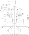
- FIG. 1 illustrates, schematically, a rotary actuator system in accordance with the disclosure
- FIG. 2 shows a cross-sectional view of a seal element in accordance with the disclosure.
- FIG. 3 illustrates a drainage path through the seal element FIG. 2 in use.
- a valve operating system 2 comprises a rotary actuator 4 having a first static, actuator housing 6 .
- a rotary shaft 8 is connected to a rotary drive element mechanism within the actuator housing 6 .
- the shaft 8 may have a keyed connection with a drive component within the actuator housing 6 .
- the rotary actuator 4 may include, for example, electronic components 10 arranged within the actuator housing 6 allowing for, for example, the control of the actuator 4 .
- the rotary shaft 8 in this embodiment is connected at its other end to a valve element 12 of a valve 13 .
- the valve element 12 is a butterfly valve element which is received in a duct 14 to control the flow of fluid through the duct 14 .
- the duct 14 may, for example, be part of an aircraft air conditioning system, the butterfly valve element 12 controlling the flow of air through the duct 14 .
- the valve element 12 is supported in a second static, valve housing 16 which may, for example, be integrated with a wall of the duct 14 .
- the rotary shaft 8 may form a part of the valve assembly and project therefrom for engagement with the actuator 4 as discussed above.
- the actuator system 2 further comprises a sealing arrangement 20 arranged between the actuator housing 6 and the housing 16 .
- the sealing arrangement 20 comprises a seal element 22 and an annular elastomeric biasing element 24 .
- the seal element 22 comprises a disc-shaped seal body 26 having a first axial side 28 and an opposed second axial side 30 .
- the seal body 26 further comprises a radially inner central circular opening 32 for receiving the rotary shaft 8 .
- the opening 32 has an inner periphery 34 for sealingly receiving the shaft 8 .
- the seal body 26 further comprises a radially outer rim portion 36 .
- the radially outward rim portion 36 has an axially facing annular sealing surface 38 provided on the first axial side 28 of the seal body for sealing engagement with an axially facing annular surface 40 of the adjacent first static housing 6 .
- the axially facing annular sealing surface 38 of the seal element 22 is arranged generally perpendicularly to the axis of rotation A of the rotary shaft 8 and of the central opening 32 of the seal body 26 .
- the axially facing surface 40 of the first static housing is also arranged perpendicularly to the axis of rotation A.
- the axially facing annular sealing surface 38 of the seal element 22 further comprises an annular groove 42 which extends in a circumferential direction around the axially facing annular surface 38 . The purpose of this groove 42 will be described further below.
- the radially outer rim portion 36 also comprises, on the second side 30 of the seal body 26 , an axially facing pocket 44 comprising a radially inner, axially extending lip 46 and a radially extending axially facing surface 48 .
- an axially facing pocket 44 comprising a radially inner, axially extending lip 46 and a radially extending axially facing surface 48 .
- the pocket 44 receives the annular elastomeric biasing element 24 .
- the seal body 26 further comprises at least one drainage passage 50 formed through the outer rim portion 36 from an inlet 52 on the second axial side of the seal body 26 to an outlet 54 on a radially outer portion 56 of the rim portion 36 .
- the at least one drainage passage 50 provides a fluid drainage path P from the second axial side 30 of the seal body 26 to the radially outer portion 56 of the rim portion 36 which bypasses the axially facing pocket 44 and the elastomeric biasing element 24 .
- a plurality, for example four, drainage passages 50 may be provided. Of course more or fewer drainage passages 50 may be provided.
- the drainage passages 50 may be circumferentially equi-spaced about the seal body 26 , although other arrangements of drainage passages 50 may be used. Providing a plurality of drainage passages 50 will help ensure that there is no pooling of liquid around the seal inner circumference in any potential actuator or valve orientation.
- the drainage passages 50 extend in a direction R having a component from the second axial side 30 of the seal body 26 towards the first axial side of the seal body 26 .
- the drainage passages 50 extend at an angle ⁇ to the radial direction R.
- the inlets 52 of the drainage passages 50 are formed at the base of the lip 46 defining the pocket 44 .
- the outlets 54 of the drainage passages 50 are formed in a sloping radially outer surface 58 of the rim portion 36 .
- Other configurations of drainage passages are of course possible, as long as they provide the necessary bypass passage P.
- the radially outer surface 58 may not be sloped in other embodiments and the drainage passages 50 may extend parallel to the radial direction R.
- the seal body 26 may be a one-piece body.
- the seal body 26 may, for example, be constructed from a relatively low friction material such as PTFE. This will provide a relatively low friction sealing interface between the inner surface 34 of the central opening 32 and the shaft 8 .
- the seal body 26 may be made in more than one part example of different materials.
- the seal body pocket 44 receives an annular elastomeric biasing element 24 .
- the biasing element 24 is an O-ring of a suitably resilient material, for example silicone rubber.
- the biasing element 24 is restrained from moving radially inwardly by means of the lip 46 of the pocket 44 and is arranged axially between the radially extending axially facing surface 48 of the pocket 44 and opposed surface 60 of the second static housing 16 .
- the biasing element 24 is compressed in the axial direction between these surfaces 48 , 60 when the first static housing 6 is mounted to the second static housing 16 .
- the first and second static housings 6 , 16 may comprise mounting flanges 62 , 64 which are clamped together by a clamping ring 66 .
- a clamping ring 66 may be used, for example releasable fasteners such as nuts and bolts.
- the dimensioning of the various components is such that when so clamped, the biasing element 24 will be compressed between the axially facing surface 48 of the pocket 44 and the opposed surfaces 60 of the second static housing 16 . This axial compression biases the axially facing annular sealing surface 38 of the seal element 22 into sealing contact with the annular surface 40 of the first static housing 6 . It also prevents leakage of fluid around the outer periphery of the seal element 22 .
- first and second additional seals 70 , 72 are provided between the first static housing 6 and the rotary shaft 8 and the second static housing 16 and the rotary shaft 8 respectively. These additional seals 70 , 72 are intended to reduce any flow of fluid into the rotary actuator 4 from the duct 14 along the shaft 8 .
- a bearing 74 for the shaft 8 may also be provided in the second static housing 16 as illustrated schematically in FIG. 1 . In other arrangements, a bearing may instead or additionally be provided in the valve housing 16 on the opposite side of the valve element 12 . In other arrangements, a bearing may be instead or additionally provided in the actuator housing 6 to the right of the first additional seal 70 .
- fluid for example condensed water may attempt to flow from the duct 14 along the shaft 8 between the first and second housings 6 , 16 and into the rotary actuator 4 .
- the additional seals 70 , 72 may themselves prevent some flow of fluid, but in the event of the water freezing and thawing, the seals 70 , 72 may remain at least partially frozen due to the thermal mass around them, even after the water has thawed which may lead to the effectiveness of the seal being compromised which in turn means that water may penetrate the first static housing 6 and possibly adversely interfere with components of the actuator such as electronic components 10 .
- the sealing arrangement 20 of the present disclosure is intended to mitigate such problems and reduce significantly or avoid penetration of water into the first static housing 6 .
- water W may flow along the shaft 8 through the second additional seal towards the first additional seal 70 .
- the seal element 22 of the disclosure reduces or prevents such flow.
- the inner periphery 34 of the central opening 32 of the seal element 22 forms a dynamic seal with the shaft 8 . This reduces or prevents flow of water W along the shaft 8 towards the first additional seal 70 .
- Water W is diverted away from the shaft and flows radially outwardly along the second side 30 of the seal element 22 towards the drainage passages 50 . Water W is prevented from flowing around the annular biasing element 24 due to the contact thereof with the annular surfaces 48 , 60 of the seal element 22 and second static housing 16 .
- the drainage passages 50 permit water to drain from that space 76 to the outer circumferential surface 56 of the seal element 22 radially outwardly of the surface 40 of the first static housing 6 . From there, the water may be routed to atmosphere through suitable openings or evaporation.
- the drainage passage 50 also prevents a pressure build-up in the space 74 and permits pressure equalisation with the surroundings, thereby reducing pressure loading on the second additional seal 72 .
- the radially inner lip 46 of the pocket 44 is circumferentially continuous. However, this is not essential and the lip ( 46 ) may be formed with a plurality of circumferentially spaced sections which will still locate the biasing element 24 radially. Yet further embodiments, the pocket 44 may be formed as a groove in the second side 30 of the rim portion 36 .
- the axially facing surface 48 of the pocket 44 may not be planar as illustrated but may be curved, provided it includes an axially facing portion.
- embodiments of the disclosure provide an advantageous arrangement which will reduce or prevent ingress of moisture to sensitive electronic components in a rotary actuator.
- the disclosed embodiment has no moving parts and is therefore potentially highly reliable.
- the system may easily be provided with mistake proofing features to avoid installation of the seal element in an incorrect orientation.
- the disclosure can be applied to new installations or as a retrofit to existing installations. It may easily be installed using standard tools and fasteners and may easily be adapted to various applications by suitable sizing.
Abstract
Description
Claims (14)
Applications Claiming Priority (3)
| Application Number | Priority Date | Filing Date | Title |
|---|---|---|---|
| EP17183854 | 2017-07-28 | ||
| EP17183854.3 | 2017-07-28 | ||
| EP17183854.3A EP3434940B1 (en) | 2017-07-28 | 2017-07-28 | Seal |
Publications (2)
| Publication Number | Publication Date |
|---|---|
| US20190032785A1 US20190032785A1 (en) | 2019-01-31 |
| US10962116B2 true US10962116B2 (en) | 2021-03-30 |
Family
ID=59501294
Family Applications (1)
| Application Number | Title | Priority Date | Filing Date |
|---|---|---|---|
| US16/047,391 Active 2039-06-28 US10962116B2 (en) | 2017-07-28 | 2018-07-27 | Seal |
Country Status (2)
| Country | Link |
|---|---|
| US (1) | US10962116B2 (en) |
| EP (1) | EP3434940B1 (en) |
Citations (16)
| Publication number | Priority date | Publication date | Assignee | Title |
|---|---|---|---|---|
| US2703974A (en) | 1952-03-05 | 1955-03-15 | Gen Electric | Flexible guard sleeve and water deflector for clothes washing machines |
| US3626770A (en) * | 1970-01-30 | 1971-12-14 | Ite Imperial Corp | Back-up seal for bellows |
| US4254793A (en) * | 1979-01-15 | 1981-03-10 | Domer Scaramucci | Ball valve having valve chamber venting seal assemblies |
| US4406459A (en) * | 1982-06-18 | 1983-09-27 | United Technologies Corporation | Oil weepage return for carbon seal plates |
| US4406460A (en) * | 1982-11-01 | 1983-09-27 | United Technologies Corporation | Anti-weepage valve for rotating seals |
| US4928978A (en) * | 1988-04-07 | 1990-05-29 | United Technologies Corporation | Rotating shaft seal |
| US6472786B1 (en) | 2000-11-17 | 2002-10-29 | Ametek, Inc. | Bearing protection assembly for motors |
| US20040021007A1 (en) | 2002-08-01 | 2004-02-05 | Hakala John E. | Nozzle deflector element |
| US7265468B1 (en) | 2005-11-22 | 2007-09-04 | Mancl Dennis J | Water repellent motor sleeve |
| US20080110515A1 (en) | 2004-08-18 | 2008-05-15 | Waters Investments Limited | Defined Lead Path For High Pressure Seal |
| FR2977650A1 (en) | 2011-07-05 | 2013-01-11 | Valeo Sys Controle Moteur Sas | Regulation valve for fluid circulation channel of exhaust gas recirculation system of internal combustion engine of vehicle, has vent channel opening into connecting pipe between upper and lower joints to set atmospheric pressure in pipe |
| US9562608B2 (en) | 2014-12-24 | 2017-02-07 | Aisin Seiki Kabushiki Kaisha | Rotary shaft seal structure for drive system of vehicle |
| US20180355757A1 (en) * | 2017-06-08 | 2018-12-13 | United Technologies Corporation | Sealing configurations with active cooling features |
| US20190154156A1 (en) * | 2016-07-01 | 2019-05-23 | Nippon Pillar Packing Co., Ltd. | Mechanical seal |
| US10352456B2 (en) * | 2013-11-06 | 2019-07-16 | United Technologies Corporation | Axial scoop seal plate |
| US10422245B2 (en) * | 2017-03-28 | 2019-09-24 | United Technologies Corporation | Seal element with internal lubricant plenum for rotational equipment |
-
2017
- 2017-07-28 EP EP17183854.3A patent/EP3434940B1/en active Active
-
2018
- 2018-07-27 US US16/047,391 patent/US10962116B2/en active Active
Patent Citations (16)
| Publication number | Priority date | Publication date | Assignee | Title |
|---|---|---|---|---|
| US2703974A (en) | 1952-03-05 | 1955-03-15 | Gen Electric | Flexible guard sleeve and water deflector for clothes washing machines |
| US3626770A (en) * | 1970-01-30 | 1971-12-14 | Ite Imperial Corp | Back-up seal for bellows |
| US4254793A (en) * | 1979-01-15 | 1981-03-10 | Domer Scaramucci | Ball valve having valve chamber venting seal assemblies |
| US4406459A (en) * | 1982-06-18 | 1983-09-27 | United Technologies Corporation | Oil weepage return for carbon seal plates |
| US4406460A (en) * | 1982-11-01 | 1983-09-27 | United Technologies Corporation | Anti-weepage valve for rotating seals |
| US4928978A (en) * | 1988-04-07 | 1990-05-29 | United Technologies Corporation | Rotating shaft seal |
| US6472786B1 (en) | 2000-11-17 | 2002-10-29 | Ametek, Inc. | Bearing protection assembly for motors |
| US20040021007A1 (en) | 2002-08-01 | 2004-02-05 | Hakala John E. | Nozzle deflector element |
| US20080110515A1 (en) | 2004-08-18 | 2008-05-15 | Waters Investments Limited | Defined Lead Path For High Pressure Seal |
| US7265468B1 (en) | 2005-11-22 | 2007-09-04 | Mancl Dennis J | Water repellent motor sleeve |
| FR2977650A1 (en) | 2011-07-05 | 2013-01-11 | Valeo Sys Controle Moteur Sas | Regulation valve for fluid circulation channel of exhaust gas recirculation system of internal combustion engine of vehicle, has vent channel opening into connecting pipe between upper and lower joints to set atmospheric pressure in pipe |
| US10352456B2 (en) * | 2013-11-06 | 2019-07-16 | United Technologies Corporation | Axial scoop seal plate |
| US9562608B2 (en) | 2014-12-24 | 2017-02-07 | Aisin Seiki Kabushiki Kaisha | Rotary shaft seal structure for drive system of vehicle |
| US20190154156A1 (en) * | 2016-07-01 | 2019-05-23 | Nippon Pillar Packing Co., Ltd. | Mechanical seal |
| US10422245B2 (en) * | 2017-03-28 | 2019-09-24 | United Technologies Corporation | Seal element with internal lubricant plenum for rotational equipment |
| US20180355757A1 (en) * | 2017-06-08 | 2018-12-13 | United Technologies Corporation | Sealing configurations with active cooling features |
Non-Patent Citations (1)
| Title |
|---|
| Extended European Search Report for International Application No. 17183854.3 dated Feb. 5, 2018, 5 pages. |
Also Published As
| Publication number | Publication date |
|---|---|
| US20190032785A1 (en) | 2019-01-31 |
| EP3434940A1 (en) | 2019-01-30 |
| EP3434940B1 (en) | 2020-02-26 |
Similar Documents
| Publication | Publication Date | Title |
|---|---|---|
| CN103228965B (en) | Fly valve | |
| US9038987B2 (en) | Flap assembly, in particular exhaust gas flap assembly | |
| US10202868B2 (en) | Attachment of a discharge conduit of a turbine engine | |
| KR0125009B1 (en) | Dynamic seal arrangement for impeller pump | |
| KR102091574B1 (en) | Valve and stem sealing assembly | |
| AU2007337157A1 (en) | Apparatus to seal a shaft to a diaphragm actuator | |
| US10072785B2 (en) | Conduit connector | |
| US20150001810A1 (en) | Dynamically Non Contacting Seal | |
| US10962116B2 (en) | Seal | |
| CN109611573B (en) | Ball valve geometry and dynamic seal assembly | |
| US6725993B2 (en) | Connecting arrangement for a clutch-release mechanism | |
| EP3584472A1 (en) | A mechanical seal arrangement for a flow machine | |
| US6364604B1 (en) | Vacuum pump and vacuum apparatus equipped with vacuum pump | |
| US20120118419A1 (en) | Aircraft low clearance fluid check valve | |
| US6640823B2 (en) | Fitting | |
| JPS5839275B2 (en) | Mechanical seal assembly for rotating shaft | |
| CN113137472A (en) | Assembly for a motor vehicle | |
| US11231110B2 (en) | Shaft seal having a shaft sealing ring | |
| GB2438022A (en) | A bearing protector | |
| CN113154041A (en) | Assembly for a motor vehicle | |
| US10180187B2 (en) | High moisture environment seal assembly | |
| CN108119666B (en) | Sealing lamination and valve assembly with the same | |
| US20110084226A1 (en) | Full straight-shaft sealing butterfly valve | |
| EP3293430A1 (en) | Articulating coupling assembly | |
| US20230003308A1 (en) | Valve assembly and cage for a valve assembly |
Legal Events
| Date | Code | Title | Description |
|---|---|---|---|
| FEPP | Fee payment procedure |
Free format text: ENTITY STATUS SET TO UNDISCOUNTED (ORIGINAL EVENT CODE: BIG.); ENTITY STATUS OF PATENT OWNER: LARGE ENTITY |
|
| AS | Assignment |
Owner name: UTC AEROSPACE SYSTEMS WROCLAW SP. Z O.O., POLAND Free format text: ASSIGNMENT OF ASSIGNORS INTEREST;ASSIGNOR:KWASNIEWSKI, PAWEL;REEL/FRAME:046763/0953 Effective date: 20180301 Owner name: CLAVERHAM LIMITED, UNITED KINGDOM Free format text: ASSIGNMENT OF ASSIGNORS INTEREST;ASSIGNOR:UTC AEROSPACE SYSTEMS WROCLAW SP. Z O.O.;REEL/FRAME:046763/0957 Effective date: 20180302 Owner name: CLAVERHAM LIMITED, UNITED KINGDOM Free format text: ASSIGNMENT OF ASSIGNORS INTEREST;ASSIGNOR:EDMOND, GEORGE;REEL/FRAME:046763/0941 Effective date: 20180306 Owner name: CLAVERHAM LIMITED, UNITED KINGDOM Free format text: ASSIGNMENT OF ASSIGNORS INTEREST;ASSIGNORS:ENNOR, SIMON;ROBINS, JONATHAN;BOWLES, PAUL;REEL/FRAME:046763/0945 Effective date: 20180306 |
|
| STPP | Information on status: patent application and granting procedure in general |
Free format text: DOCKETED NEW CASE - READY FOR EXAMINATION |
|
| STPP | Information on status: patent application and granting procedure in general |
Free format text: AWAITING TC RESP., ISSUE FEE NOT PAID |
|
| STPP | Information on status: patent application and granting procedure in general |
Free format text: PUBLICATIONS -- ISSUE FEE PAYMENT VERIFIED |
|
| STCF | Information on status: patent grant |
Free format text: PATENTED CASE |