US10961972B2 - Method and apparatus to control an ignition system - Google Patents
Method and apparatus to control an ignition system Download PDFInfo
- Publication number
- US10961972B2 US10961972B2 US15/036,434 US201415036434A US10961972B2 US 10961972 B2 US10961972 B2 US 10961972B2 US 201415036434 A US201415036434 A US 201415036434A US 10961972 B2 US10961972 B2 US 10961972B2
- Authority
- US
- United States
- Prior art keywords
- current
- switch
- control unit
- spark plug
- primary
- Prior art date
- Legal status (The legal status is an assumption and is not a legal conclusion. Google has not performed a legal analysis and makes no representation as to the accuracy of the status listed.)
- Active, expires
Links
Images


Classifications
-
- F—MECHANICAL ENGINEERING; LIGHTING; HEATING; WEAPONS; BLASTING
- F02—COMBUSTION ENGINES; HOT-GAS OR COMBUSTION-PRODUCT ENGINE PLANTS
- F02P—IGNITION, OTHER THAN COMPRESSION IGNITION, FOR INTERNAL-COMBUSTION ENGINES; TESTING OF IGNITION TIMING IN COMPRESSION-IGNITION ENGINES
- F02P15/00—Electric spark ignition having characteristics not provided for in, or of interest apart from, groups F02P1/00 - F02P13/00 and combined with layout of ignition circuits
- F02P15/10—Electric spark ignition having characteristics not provided for in, or of interest apart from, groups F02P1/00 - F02P13/00 and combined with layout of ignition circuits having continuous electric sparks
-
- F—MECHANICAL ENGINEERING; LIGHTING; HEATING; WEAPONS; BLASTING
- F02—COMBUSTION ENGINES; HOT-GAS OR COMBUSTION-PRODUCT ENGINE PLANTS
- F02D—CONTROLLING COMBUSTION ENGINES
- F02D41/00—Electrical control of supply of combustible mixture or its constituents
- F02D41/009—Electrical control of supply of combustible mixture or its constituents using means for generating position or synchronisation signals
-
- F—MECHANICAL ENGINEERING; LIGHTING; HEATING; WEAPONS; BLASTING
- F02—COMBUSTION ENGINES; HOT-GAS OR COMBUSTION-PRODUCT ENGINE PLANTS
- F02P—IGNITION, OTHER THAN COMPRESSION IGNITION, FOR INTERNAL-COMBUSTION ENGINES; TESTING OF IGNITION TIMING IN COMPRESSION-IGNITION ENGINES
- F02P17/00—Testing of ignition installations, e.g. in combination with adjusting; Testing of ignition timing in compression-ignition engines
- F02P17/12—Testing characteristics of the spark, ignition voltage or current
-
- F—MECHANICAL ENGINEERING; LIGHTING; HEATING; WEAPONS; BLASTING
- F02—COMBUSTION ENGINES; HOT-GAS OR COMBUSTION-PRODUCT ENGINE PLANTS
- F02P—IGNITION, OTHER THAN COMPRESSION IGNITION, FOR INTERNAL-COMBUSTION ENGINES; TESTING OF IGNITION TIMING IN COMPRESSION-IGNITION ENGINES
- F02P3/00—Other installations
- F02P3/02—Other installations having inductive energy storage, e.g. arrangements of induction coils
- F02P3/04—Layout of circuits
- F02P3/0407—Opening or closing the primary coil circuit with electronic switching means
- F02P3/0435—Opening or closing the primary coil circuit with electronic switching means with semiconductor devices
- F02P3/0442—Opening or closing the primary coil circuit with electronic switching means with semiconductor devices using digital techniques
-
- F—MECHANICAL ENGINEERING; LIGHTING; HEATING; WEAPONS; BLASTING
- F02—COMBUSTION ENGINES; HOT-GAS OR COMBUSTION-PRODUCT ENGINE PLANTS
- F02P—IGNITION, OTHER THAN COMPRESSION IGNITION, FOR INTERNAL-COMBUSTION ENGINES; TESTING OF IGNITION TIMING IN COMPRESSION-IGNITION ENGINES
- F02P3/00—Other installations
- F02P3/02—Other installations having inductive energy storage, e.g. arrangements of induction coils
- F02P3/04—Layout of circuits
- F02P3/05—Layout of circuits for control of the magnitude of the current in the ignition coil
- F02P3/051—Opening or closing the primary coil circuit with semiconductor devices
- F02P3/053—Opening or closing the primary coil circuit with semiconductor devices using digital techniques
-
- F—MECHANICAL ENGINEERING; LIGHTING; HEATING; WEAPONS; BLASTING
- F02—COMBUSTION ENGINES; HOT-GAS OR COMBUSTION-PRODUCT ENGINE PLANTS
- F02P—IGNITION, OTHER THAN COMPRESSION IGNITION, FOR INTERNAL-COMBUSTION ENGINES; TESTING OF IGNITION TIMING IN COMPRESSION-IGNITION ENGINES
- F02P3/00—Other installations
- F02P3/02—Other installations having inductive energy storage, e.g. arrangements of induction coils
- F02P3/04—Layout of circuits
- F02P3/055—Layout of circuits with protective means to prevent damage to the circuit, e.g. semiconductor devices or the ignition coil
- F02P3/0552—Opening or closing the primary coil circuit with semiconductor devices
- F02P3/0554—Opening or closing the primary coil circuit with semiconductor devices using digital techniques
Definitions
- the present invention relates to an ignition system and method of controlling spark plugs. It has particular but not exclusive application to systems which are adapted to provide a continuous spark, such as a multi-spark plug ignition system.
- Ignition engines that use very lean air-fuel mixtures have been developed, that is, having a higher air composition to reduce fuel consumption and emissions.
- Prior art systems generally use large, high energy, single spark ignition coils, which have a limited spark duration and energy output.
- multi-charge ignition systems have been developed. Multi-charge systems produce a fast sequence of individual sparks, so that the output is a long quasi-continuous spark.
- Multi-charge ignition methods have the disadvantage that the spark is interrupted during the recharge periods, which has negative effects, particularly noticeable when high turbulences are present in the combustion chamber. For example this can lead to misfire, resulting in higher fuel consumption and higher emissions.
- EP2325476 discloses a multi-charge ignition system without these negative effects and, at least partly, producing a continuous ignition spark over a wide area of burn voltage, delivering an adjustable energy to the spark plug and providing with a burning time of the ignition fire that can be chosen freely.
- the PWM-signal of the step-down-converter stage is adapted to a fixed value, which results in a non-stable primary current under various conditions.
- a method for controlling an ignition system which includes a spark plug control unit adapted to control at least two coil stages so as to successively energise and de-energise the at least two coil stages to provide a current to a spark plug, including two stages comprising a first transformer including a first primary winding inductively coupled to a first secondary winding; a second transformer including a second primary winding inductively coupled to a second secondary winding; the spark plug control unit enabled to simultaneously energize and deenergize the first primary winding and the second primary winding by simultaneously switching on and off two corresponding switches to sequentially energize and de-energize the first primary winding and the second primary winding by sequentially switching on and off both of the two corresponding switches to maintain a continuous ignition fire, and includes a step-down converter stage located between the spark plug control unit and the at least two coil stages, the step-down converter including a switch and a diode, the spark plug control unit being enabled to switch off the switch, wherein the method provides control to limit a secondary current peak
- FIG. 1 is a schematic diagram of an ignition system to which aspects of the invention can be applied.
- FIGS. 2 a , 2 b , and 2 c illustrate a standard ignition cycle of the CMC-system indicating schematic current traces.
- FIG. 3 illustrates an ignition system and its connectivity to a vehicle electronic control unit (ECU).
- ECU vehicle electronic control unit
- FIG. 4 illustrates a communication protocol according to one aspect of the invention which can be used to control ignition systems.
- FIG. 5 shows the results of operation of the step down converter in such control.
- FIG. 6 shows a communication protocol according to one aspect of the invention which can be used to control ignition systems including a further pulse.
- FIG. 7 shows a schematic circuit diagram of an ignition system according to a further aspect of the invention.
- FIGS. 8 a and 8 b show the results of operation of the down converter to reduce secondary current peak.
- FIG. 9 shows a flow chart illustrating a down-ramping algorithm according to one aspect.
- FIGS. 10 a , 10 b , and 10 c show traces of currents where the algorithm of FIG. 9 is implemented.
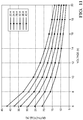
- FIG. 11 shows the relationship between the duty cycle, battery voltage and maximum primary current switching threshold in step-down-operation.
- Ipthmax Maximum primary current switching threshold in step-down-operation
- Ipthmin Minimum primary current switching threshold in step-down-operation
- FIG. 1 shows the circuitry of a prior art coupled-multi-charge ignition system for producing a continuous ignition spark over a wide area of burn voltage servicing a single set of gapped electrodes in a spark plug such as might be associated with a single combustion cylinder of an internal combustion engine (not shown).
- the CMC system uses fast charging ignition coils (L 1 -L 4 ), including primary windings, L 1 , L 2 to generate the required high DC-voltage.
- the voltage and wound on a common core K 1 forming a first transformer and secondary windings L 3 , L 4 wound on another common core K 2 are forming a second transformer.
- the two coil ends of the first and second primary windings L 1 , L 3 may be alternately switched to a common ground such as a chassis ground of an automobile by electrical switches Q 1 , Q 2 .
- These switches Q 1 , Q 2 are preferably Insulated Gate Bipolar Transistors. Resistor R 1 for measuring the primary current Ip that flows from the primary side is connected between the switches Q 1 , Q 2 and ground, while resistor R 2 for measuring the secondary current Is that flows from the secondary side is connected between the diodes D 1 , D 2 and ground.
- the low-voltage ends of the secondary windings L 2 , L 4 may be coupled to a common ground or chassis ground of an automobile through high-voltages diodes D 1 , D 2 .
- the high-voltage ends of the secondary ignition windings L 2 , L 4 are coupled to one electrode of a gapped pair of electrodes in a spark plug through conventional means.
- the other electrode of the spark plug is also coupled to a common ground, conventionally by way of threaded engagement of the spark plug to the engine block.
- the primary windings L 1 , L 3 are connected to a common energizing potential which in the present embodiment is assumed to correspond to conventional automotive system voltage in a nominal 12V automotive electrical system and is in the figure the positive voltage of battery.
- the charge current can be supervised by an electronic control circuit that controls the state of the switches Q 1 , Q 2 .
- the control circuit is for example responsive to engine spark timing (EST) signals, supplied by the ECU, to selectively couple the primary windings L 1 and L 2 to system ground through switches Q 1 and Q 2 respectively controlled by signals Igbt 1 and Igbt 2 , respectively.
- Measured primary current Ip and secondary current Is are sent to control unit.
- the common energizing potential of the battery is coupled by way of an ignition switch M 1 to the primary windings L 1 , L 3 at the opposite end that the grounded one.
- Switch M 1 is preferably a MOSFET transistor.
- a diode D 3 or any other semiconductor switch e.g.
- MOSFET MOSFET
- Control unit is enabled to switch off switch M 1 by means of a signal FET.
- the diode D 3 or any other semiconductor switch will be switched on when M 1 is off and vice versa.
- the control circuit is operative to provide an extended continuous high-energy arc across the gapped electrodes.
- switches M 1 , Q 1 and Q 2 are all switched on, so that the delivered energy of the power supply is stored in the magnetic circuit of both transformers (T 1 , T 2 ).
- both primary windings are switched off at the same time by means of switches Q 1 and Q 2 .
- On the secondary side of the transformers a high voltage is induced and an ignition spark is created through the gapped electrodes of the spark plug.
- switch Q 1 is switched on and switch Q 2 is switched off (or vice versa).
- the first transformer (L 1 , L 2 ) stores energy into its magnetic circuit while the second transformer (L 3 , L 4 ) delivers energy to spark plug (or vice versa).
- the control unit detects it and switches transistor M 1 off.
- the stored energy in the transformer (L 1 , L 2 or L 3 , L 4 ) that is switched on (Q 1 , or Q 2 ) impels a current over diode D 3 (step-down topology), so that the transformer cannot go into the magnetic saturation, its energy being limited.
- transistor M 1 will be permanently switched on and off to hold the energy in the transformer on a constant level.
- steps 3 to 5 will be iterated by sequentially switching on and off switches Q 1 and Q 2 as long as the control unit switches both switches Q 1 and Q 2 off.
- FIGS. 2 a -2 c show a timeline of ignition system current;
- FIG. 2 a shows a trace representing primary current Ip along time.
- FIG. 2 b shows the secondary current Is.
- FIG. 2 c shows the signal on the EST line which is sent from the ECU to the ignition system control unit and which indicates ignition time.
- step 1 i.e. M 1 , Q 1 and Q 2 switched on
- the primary current Ip is increasing rapidly with the energy storage in the transformers.
- step 2 i.e. Q 1 and Q 2 switched off
- the secondary current Is is increasing and a high voltage is induced so as to create an ignition spark through the gapped electrodes of the spark plug.
- step 3 i.e.
- step 4 comparison is made between primary current Ip and a limit Ipth. When Ip exceeds Ipth M 1 is switched off, so that the “switched on” transformer cannot go into the magnetic saturation, by limiting its stored energy. The switch M 1 is switched on and off in this way, that the primary current Ip is stable in a controlled range.
- step 5 comparison is made between the secondary current Is and a secondary current threshold level Isth. If Is ⁇ Isth, Q 1 is switched off and Q 2 switched on (or vice versa).
- steps 3 to 5 will be iterated by sequentially switching on and off Q 1 and Q 2 as long as the control unit switches both Q 1 and Q 2 off. Because of the alternating charging and discharging of the two transformers the ignition system delivers a continuous ignition fire.
- the above describes the circuitry and operation of a prior art ignition system to provide a background to the current invention. In some aspects of the invention the above circuitry can be used. The invention provides various solutions to enhance performance and reduce spark-plug wear.
- FIG. 3 shows the connectivity of the vehicle ECT to the spark plug control circuitry via an EST line, which is used according to one aspect in signalling i.e. sending via appropriate communications protocol, voltage or current parameters to the spark plug circuitry control unit which controls the ignition circuitry.
- the EST line typically provides the control unit with a pulse which indicates the dwell time to be implemented.
- the control unit of the coil is separate to the ECU and the EST-signal (engine spark time) is delivered by the ECU by a e.g. a Boolean signal—see FIG. 2 c .
- this controlled directly a switch/IGBT inside the ignition coil and in current systems this controls also the time of the burn time of the MultiCharge-cycle.
- FIG. 3 shows the connectivity of the vehicle ECT to the spark plug control circuitry via an EST line, which is used according to one aspect in signalling i.e. sending via appropriate communications protocol, voltage or current parameters to the spark plug circuitry control unit which controls the ignition circuitry.
- the EST line typically provides
- the invention provides a communication protocol to control parameters such as those relating to the current or voltages in the primary and/or secondary coils.
- the invention provides a communication protocol to control parameters such as those relating to the current or voltages in the primary and/or secondary coils.
- FIGS. 2 a -2 c show the current a primary coil and secondary coil over a complete ignition cycle.
- FIG. 4 illustrates a communication protocol according to one example which can be used to control ignition systems; particularly the primary and secondary current(s) and/or voltage(s). Such methods may be used in conjunction with the circuitry shown in FIG. 1 a , though the methodology is not limited to such circuitry, and some aspects are applicable to ignition systems where there is only one coil stage.
- FIGS. 2 a and b shows the current a primary coil and secondary coil over a complete ignition cycle.
- FIG. 2 c shows the EST line which is used to provide a communications protocol to a control unit which controls the ignition circuitry, such as that of FIG. 1 .
- the current in a/the primary coil is ramped up to reach a maximum primary current peak. The value of this peak will also affect the maximum secondary breakdown voltage.
- the current in the primary coil is discharged causing a current to develop rapidly in the secondary coil.
- the charging/discharging cycle is repeated multiple times, alternatively by each coil stage, thus providing a continuous spark.
- high currents may develop in the secondary coils.
- a (first) communication pulse 1 is provided on the EST line, the duration of which indicates to the control unit the maximum primary current (threshold) in the Coupled-MultiCharge-Mode; what this parameter should be set at.
- the EST line is used to forward parameters other than dwell or CMC time, and can include units other than time and be representative of current or voltages (e.g. thresholds for comparison) during any stage of operation.
- the control of this current level may be implemented by appropriate control by the control unit of the step-down converter.
- the primary current may be limited by appropriate operation of the step-down-converter. If the primary current reaches this level, current will be limited by the step down converter.
- the control unit will accordingly control of the step down converter stage by e.g. appropriately switching on/off the FET M 1 .
- the control unit has means to compare the primary or secondary currents with e.g. (threshold) parameters sent along the EST line. So in other words the step-down-converter can be used to limit the primary current to a desired value Ipthmax and to hold it constant at this specified level. Traditionally this parameter may be stored in the control unit.
- Ipthmax and or Ipthmin can be set by the ECU, and using appropriate communication protocol can be sent to the control unit.
- Ipmax that is the max peak value of primary current as well as Ipth (the threshold e.g. max primary current in CMC operation)
- Ipth the threshold e.g. max primary current in CMC operation
- the value of the primary current can be compared with the thresholds by the control unit.
- the step down converter is appropriately controlled e.g. by pulsing switch M 1 , i.e. switching on and off.
- the primary current Ip may be measured during the step down cycle and switching M 1 on and off as follows: switching M 1 , the current flows over L 1 , Q 1 , R 1 and D 3 and is decreasing.
- the control unit monitors the voltage. After the primary current reaches a level Ipthmin, M 1 will be switched on again.
- Such methods may be used in conjunction with the circuitry shown in FIG. 1 , though the methodology is not limited to such circuitry, and some aspects are applicable to ignition systems where there is only one coil stage.
- aspect of the invention include sending any appropriate current or voltage parameter from the ECU to the spark plug control unit; some of which will be explained in more detail hereinafter.
- the important point in this aspect is that the EST line is used other than for sending CMC and dwell times to the control unit.
- the levels of current and voltage parameters are indicated by the duration of the pulses. However the levels may be signaled by other methods such as the number of very short pulses e.g. within a set time being indicative of the levels.
- the pulse sent along the EST line from the ECU to the control unit may indicate secondary current parameters (e.g. limits or thresholds for comparison with measured values), or any other parameter of primary or secondary coil current/voltage, as will be explained below.
- secondary current parameters e.g. limits or thresholds for comparison with measured values
- the parameters of secondary currents are controlled, e.g. during the CMC phase, by similar methodology.
- parameters of the secondary current threshold Isth and the secondary current amplitude Isamp are sent using a communication protocol from the ECU to the control unit. By appropriate control of these parameters, it is possible to control the output power of the system. These parameters may be compared with measured values by the ECU and used to appropriately control the operation of the coil stages.
- the parameter Isth is adapted dependent on the burn voltage of the spark plug, but before Isth is set by the communication of the ECU—this is a preferred wanted value and the calculation of Ipth is done based on this initial set value. If the load (burn-voltage) is too high then the secondary current will be ramped down; thus this may involve setting adaptively said second predetermined current threshold (Ismin) to the level of energy stored in the transformer that is switched off.
- the variable Ipmax is the maximum primary current after the initial charge of the system. According to one aspect this parameter also be controlled by comparing to a threshold value(s).
- the threshold values may be either stored in the control unit or sent along the EST lines in a similar fashion to the max primary current (threshold during CMC) stage. Again the value of Ip can be measured and determine against a threshold Ipmax. So to recap this value is stored in the control unit, or can be transmitted to the control unit from the ECU along the EST line.
- the step down converter will hold the primary current Ip on the specified level defined by Ipmax.
- the current is similar to the current in FIG. 5 , so it has a small hysteresis.
- FIG. 6 shows a communication protocol where there is a second pulse 2 ; the second pulse length indicates the max primary current peak.
- the max primary current peak can be controlled on its own by means of a single pulse i.e. not in conjunction with any other parameter.
- the parameter Isth is adapted dependent on the burn voltage of the spark plug, but before Isth is set by the communication of the ECU—this is a preferred wanted value and the calculation of Ipth is done based on this initial set value. If the load (burn-voltage) is too high then the secondary current will be ramped down; thus this may involve setting adaptively said second predetermined current threshold (Ismin) to the level of energy stored in the transformer that is switched off.
- Ton+Toff const., that means it is a pulse width modulated signal.
- Ton+Toff const., that means it is a pulse width modulated signal.
- the PID controller controls the primary current to the wanted value Ipthmax.
- the controlled system represents the ignition coil.
- Ub and Ipthmax one value for m can be observed (truth table, as it was shown in the last figure).
- FIG. 11 shows the relationship between the duty cycle, Ub and Ipthmax.
- the points between the data points can be interpolated linear.
- the duty cycle can be set based on a lookup table that depends on Ub and Ipthmax.
- FIG. 7 shows the circuit that is used to control the system; it is similar to that of FIG. 1 but includes mean to measure the voltage at the high voltage HV-diodes (D 1 and D 2 ).
- the supply voltage (Ubat) can additionally be measured.
- the system is controlled by measuring the primary current Ip, the secondary current Is and the voltage D 1 , D 2 at the diodes.
- the duty-cycle of the PWM-signal for the Step-Down-Converter is appropriately controlled.
- the primary and secondary currents can be measured by a shunt and used to obtain voltages.
- the voltage divider is in a range of ⁇ 1000-2000.
- the supply voltage Ubat is measured by the use of a voltage divider—here the voltage divider is in a range of ⁇ 2-20.
- circuitry in FIG. 7 can be used in general to measure the voltages at the secondary stages and compare these with e.g. thresholds or values which may be stored in the control unit.
- the EST line may be used to signal any threshold or other voltage values determined by the ECU.
- the current or voltage parameters with respect to one or more coil stages and for any phase may be sent according to an appropriate protocol from the ECU to the control unit. According to aspects this parameters are indicated by the duration of pulses sent to the control unit from the ECU. In a simple embodiment just one parameter is sent to the control unit a single pulse is sent on the EST line. However where more than one parameter is sent form the ECU, more than one pulse may be sent. One or more of the following parameters may be sent: Maximum primary current peak Ipmax; Secondary current switching threshold in CMC-Mode Isth; Secondary current switching amplitude in CMC-Mode Isamp, secondary or primary voltages.
- the invention provides various solutions to enhance performance and reduce spark-plug wear and in particular protect the diodes D 1 and D 2 .
- protection is provided for the diodes.
- the voltage at the diodes is detected/measured and consequent to the measured voltage, appropriate protection is implemented. For example, if the voltage at the diodes reaches a specific threshold, the control unit detects this voltage and will protect the diodes from too high voltages.
- FIG. 7 circuitry described above can be used to provide such control. So again compared with the FIG. 1 circuitry the voltage at the high voltage diodes (D 1 and D 2 ) is measured by providing lines to the control unit. The control unit includes means to measure these voltages and where appropriate, compare with thresholds.
- FIG. 7 also shows an example of the circuitry used to implement this aspect with a multi-stage system; however aspects of the invention can be applied to spark plug control systems having just one stage;
- FIG. 7 shows an example of the circuitry used to implement this aspect with a multi-stage system.
- This figure shows circuitry which thus includes two connections (lines) which are connected at one point between the secondary coil stage and the respective diodes, and at the other are connected to the control unit. These lines are used to feed the voltage into the control unit which can measure the voltages input to it, so as to detect/measure the voltage at the two diodes.
- control unit determines if either, or both of these voltages, are above a threshold and if so implement protection strategies.
- protection is implemented by switching both D 1 and D 2 on by switching Q 1 and Q 2 off. Then as a result of switching Q 1 ,Q 2 , the diodes are switched on in a forward direction.
- the battery voltage is also determined or estimated.
- the CMC-system is using two transformers to deliver energy to the secondary side.
- the critical situation for the diodes occurs ones after the initial charge respectively during the initial breakdown of both stages.
- the diodes are protected by switching both diodes into forward direction (Q 1 and Q 2 are off).
- the system is controlled in this way (switching first stage 1 off and then stage 2 ) as otherwise the diodes would need to withstand the whole breakdown voltage ( ⁇ 40 kV and more).
- the burn voltage at the spark plug decreases to values of about 1000 V (Uburn ⁇ 1000V).
- the diode in a conventional ignition system doesn't see a high voltage when they are firing, because it is switched on in forward direction.
- the critical situation for the diode occurs during the so called open load operation (no spark plug mounted at the output) and when the ignition fire is blown out initiated by turbulences in the engine.
- control unit determines if either, or both of these voltages, are above a threshold and if so implement protection strategies.
- protection is implemented by switching both D 1 and D 2 on by switching Q 1 and Q 2 off. Then as a result of this the diodes are switched on in a forward direction.
- protection is provided by switching both Q 1 and Q 2 on.
- UM Make-Voltage
- Ub battery-Voltage
- Q 1 and Q 2 are switched on until the maximum primary current Ipmax is reached and then the CMC algorithm starts from the beginning by alternating switch Q 1 and Q 2 .
- the states of Q 1 and Q 2 will be negated.
- the currents in the secondary coil stage(s) can be used in conjunction with the measured voltages by the control unit to control the step-down converter and/or either or both of the switches Q 1 and Q 2 .
- a high secondary current peak is developed in secondary coil(s) at the end of the ignition cycle as shown in FIG. 2 b . This will increase spark plug wear.
- various methods according to the invention are used to eliminate the high current peak.
- a solution is provided by switching on the step-down converter, by switching on M 1 , as well as switching on Q 1 and Q 2 when the Coupled Multi-Charge time has expired.
- This has the disadvantage in that all the energy will be dissipated to the primary side of the coil and will increase the heat losses inside the coil. This example is shown in FIGS. 8 a and 8 b.
- the methodology provides an alternative method which involves down-ramping of the secondary current at the end of the Coupled-Multi-Charge-Time. This is again can be implemented using the step-down-converter.
- Step 1 the down ramping is initiated after the CMC-time is expired.
- One of the switches Q 1 / 2 is on the other is off.
- Step 2 M 1 is switched off, so that the circuit is disconnected from the battery.
- the parameter Isamprd can be a fixed value, stored inside the control unit, this parameter is typically in a range of 20-80 mA.
- Step 4 the secondary current threshold value is compared with a minimum value Isthmin. This value Isthmin may be stored in the spark plug control unit or sent on the EST line. If the secondary current threshold is too low (Isth ⁇ Isthmin ( ⁇ 10 mA)) then the down ramping algorithm will finish, M 1 is off and Q 1 and Q 2 on.
- step 5 it is determined whether switch Q 1 is on. If so at step 6 it is made sure that Q 1 is switched off and Q 2 is switched on. If not at step S 7 it is made sure that Q 1 is switched on and Q 2 is switched off. Thus accordingly to their actual switching-states of Q 1 and Q 2 , their states will be negated, meaning switch Q 1 is switched off and Q 2 on or vice versa.
- step S 8 there may be an optional step of waiting for a minimum toggling time.
- step S 9 the measured secondary current is compared with a threshold Isth. When the measured value is less than the threshold Isth the method returns to step 3 .
- Isamprd A lower value of Isamprd will result in a faster toggling frequency of Q 1 and Q 2 .
- This parameter may be adapted experimentally dependent on the secondary inductance of the transformer.
- FIG. 7 shows the circuit that is used to control the system; it is similar to that of FIG. 1 but includes means to measure the voltage at the high voltage HV-diodes (D 1 and D 2 ).
- the supply voltage (Ubat) can additionally be measured.
- the system is controlled by measuring the primary current Ip, the secondary current Is and the voltage D 1 , D 2 at the diodes. If either of the voltages is too high (e.g. compared with a threshold—similar to the diode-protection embodiment) Q 1 , Q 2 will be switched on and M 1 off, that means the energy will be dissipated to the primary side.
- FIGS. 10 a -10 c show traces of primary and secondary currents where the algorithm of FIG. 9 is implemented.
- the internal primary current is the current measured at the shunt R 1 and the primary current is measured here before the switch M 1 .
Landscapes
- Engineering & Computer Science (AREA)
- Chemical & Material Sciences (AREA)
- Combustion & Propulsion (AREA)
- Mechanical Engineering (AREA)
- General Engineering & Computer Science (AREA)
- Ignition Installations For Internal Combustion Engines (AREA)
- Dc-Dc Converters (AREA)
Abstract
Description
Claims (11)
Applications Claiming Priority (4)
| Application Number | Priority Date | Filing Date | Title |
|---|---|---|---|
| EP13192916 | 2013-11-14 | ||
| EP20130192916 EP2873850A1 (en) | 2013-11-14 | 2013-11-14 | Method and apparatus to control a multi spark ignition system for an internal combustion engine |
| EP13192916.8 | 2013-11-14 | ||
| PCT/EP2014/074237 WO2015071245A1 (en) | 2013-11-14 | 2014-11-11 | Method and apparatus to control a multi spark ignition system for an internal combustion engine |
Publications (2)
| Publication Number | Publication Date |
|---|---|
| US20160298593A1 US20160298593A1 (en) | 2016-10-13 |
| US10961972B2 true US10961972B2 (en) | 2021-03-30 |
Family
ID=49582636
Family Applications (2)
| Application Number | Title | Priority Date | Filing Date |
|---|---|---|---|
| US15/036,428 Active US9945346B2 (en) | 2013-11-14 | 2014-11-11 | Method and apparatus to control an ignition system |
| US15/036,434 Active 2036-01-09 US10961972B2 (en) | 2013-11-14 | 2014-11-11 | Method and apparatus to control an ignition system |
Family Applications Before (1)
| Application Number | Title | Priority Date | Filing Date |
|---|---|---|---|
| US15/036,428 Active US9945346B2 (en) | 2013-11-14 | 2014-11-11 | Method and apparatus to control an ignition system |
Country Status (5)
| Country | Link |
|---|---|
| US (2) | US9945346B2 (en) |
| EP (3) | EP2873850A1 (en) |
| JP (3) | JP6286040B2 (en) |
| CN (2) | CN105705773B (en) |
| WO (3) | WO2015071245A1 (en) |
Families Citing this family (20)
| Publication number | Priority date | Publication date | Assignee | Title |
|---|---|---|---|---|
| JP6017046B2 (en) * | 2012-09-12 | 2016-10-26 | ローベルト ボツシユ ゲゼルシヤフト ミツト ベシユレンクテル ハフツングRobert Bosch Gmbh | Ignition device for internal combustion engine |
| EP2873850A1 (en) * | 2013-11-14 | 2015-05-20 | Delphi Automotive Systems Luxembourg SA | Method and apparatus to control a multi spark ignition system for an internal combustion engine |
| JP6442928B2 (en) * | 2014-08-27 | 2018-12-26 | 株式会社デンソー | Ignition system for internal combustion engines |
| GB201519702D0 (en) * | 2015-11-09 | 2015-12-23 | Delphi Automotive Systems Lux | Method and apparatus to control an ignition system |
| GB201519699D0 (en) | 2015-11-09 | 2015-12-23 | Delphi Automotive Systems Lux | Method and apparatus to control an ignition system |
| JP6324432B2 (en) | 2016-04-12 | 2018-05-16 | 三菱電機株式会社 | Ignition control device and ignition control method for internal combustion engine |
| GB2549251B (en) * | 2016-04-13 | 2019-11-13 | Delphi Automotive Systems Lux | Method and apparatus to control an ignition system |
| JP6581542B2 (en) * | 2016-06-08 | 2019-09-25 | 日立オートモティブシステムズ株式会社 | Ignition control device for internal combustion engine |
| JP6753288B2 (en) * | 2016-12-05 | 2020-09-09 | 株式会社デンソー | Ignition control system |
| US10731621B2 (en) | 2016-12-21 | 2020-08-04 | Caterpillar Inc. | Ignition system having combustion initiation detection |
| JP6753327B2 (en) * | 2017-02-06 | 2020-09-09 | 株式会社デンソー | Ignition control system |
| US10641232B2 (en) * | 2017-09-25 | 2020-05-05 | Ford Global Technologies, Llc | Ignition coil dwell control |
| US10995726B2 (en) | 2018-03-29 | 2021-05-04 | Woodward, Inc. | Current profile optimization |
| US10514016B1 (en) * | 2018-07-25 | 2019-12-24 | Semiconductor Components Industries, Llc | Circuit and method for soft shutdown of a coil |
| US10975827B2 (en) | 2018-09-26 | 2021-04-13 | Semiconductor Components Industries, Llc | Ignition control system with circulating-current control |
| US10907607B2 (en) * | 2019-04-24 | 2021-02-02 | Semiconductor Components Industries, Llc | Circuit and method for controlling a coil current during a soft shut down |
| WO2021215409A1 (en) | 2020-04-20 | 2021-10-28 | 株式会社 資生堂 | Agent for preventing and/or improving photoaging and/or dermal pigmentation, cosmetic method using same, and cosmetic device to be applied in said method |
| GB2599420B (en) * | 2020-10-01 | 2023-03-29 | Delphi Automotive Systems Lux | Method and apparatus to control an ignition system |
| FR3126455B1 (en) | 2021-08-26 | 2024-05-10 | Vitesco Technologies | Process for igniting a motor vehicle thermal engine |
| CN113843043B (en) * | 2021-10-29 | 2024-04-26 | 华能平凉发电有限责任公司 | Comprehensive dust removing method and device for reducing resistance of air and smoke system |
Citations (15)
| Publication number | Priority date | Publication date | Assignee | Title |
|---|---|---|---|---|
| US20020066444A1 (en) * | 2000-12-01 | 2002-06-06 | Masatoshi Ikeda | Ion current detection system and method for internal combustion engine |
| JP2008291721A (en) | 2007-05-24 | 2008-12-04 | Ngk Spark Plug Co Ltd | Ignition device for internal combustion engine |
| DE102007034399A1 (en) | 2007-07-24 | 2009-01-29 | Daimler Ag | Method for operating an ignition system for a spark-ignitable internal combustion engine of a motor vehicle and ignition system |
| DE102007034390A1 (en) | 2007-07-24 | 2009-01-29 | Daimler Ag | Method for operating an ignition system for a spark-ignitable internal combustion engine of a motor vehicle and ignition system |
| DE102008038513A1 (en) | 2008-08-20 | 2010-02-25 | Daimler Ag | Ignition system operating method for jet-guided direct-injection petrol engine of motor vehicle, involves controlling electrical switch coupled with primary coil by ignition control unit depending on decoded digital control signal |
| US20100052538A1 (en) * | 2008-08-26 | 2010-03-04 | Panasonic Electric Works Co., Ltd. | Discharge lamp lighting device, headlight device and vehicle having the same |
| US20110041804A1 (en) * | 2009-08-18 | 2011-02-24 | Woodward Governor Company | Multiplexing Drive Circuit For An AC Ignition System |
| EP2325476A1 (en) | 2009-11-20 | 2011-05-25 | Delphi Technologies, Inc. | Coupled multi-charge ignition system with an intelligent controlling circuit |
| US20110255208A1 (en) * | 2009-08-18 | 2011-10-20 | Woodward, Inc. | Multiplexing drive circuit for an ac ignition system with current mode control and fault tolerance detection |
| US20120312285A1 (en) | 2009-12-11 | 2012-12-13 | Stephan Bolz | Method for operating an ignition device for an internal combustion engine, and ignition device for an internal combustion engine for carrying out the method |
| DE102012106207B3 (en) | 2012-03-14 | 2013-05-23 | Borgwarner Beru Systems Gmbh | Method for actuating spark plug in combustion engine of vehicle, involves charging and discharging primary and secondary windings repeatedly, and disconnecting primary windings from direct current supply until start signal is produced |
| US20130152910A1 (en) | 2011-12-15 | 2013-06-20 | Fuji Electric Co., Ltd. | Internal combustion engine ignition device |
| US20130263835A1 (en) | 2010-11-23 | 2013-10-10 | Sven-Michael Eisen | Ignition Device for an Internal Combustion Engine and Method for Operating an Ignition Device for an Internal Combustion Engine |
| EP2654207A2 (en) | 2012-04-19 | 2013-10-23 | Fuji Electric Co., Ltd. | Semiconductor device including current control function and self-interrupt function |
| US20150034059A1 (en) | 2012-03-16 | 2015-02-05 | Delphi Technologies, Inc. | Ignition system |
Family Cites Families (8)
| Publication number | Priority date | Publication date | Assignee | Title |
|---|---|---|---|---|
| US2325476A (en) * | 1939-12-15 | 1943-07-27 | John E Cleve | Illuminating mirror |
| JP4335410B2 (en) * | 2000-04-28 | 2009-09-30 | 日本特殊陶業株式会社 | Ignition device for internal combustion engine |
| US7121270B1 (en) * | 2005-08-29 | 2006-10-17 | Vimx Technologies Inc. | Spark generation method and ignition system using same |
| DE102007051249A1 (en) * | 2007-10-26 | 2009-04-30 | Robert Bosch Gmbh | Device for controlling a multiple spark operation of an internal combustion engine and associated method |
| DE102008038512A1 (en) * | 2008-08-20 | 2010-02-25 | Daimler Ag | Method for operating ignition system for remotely startable internal combustion engine of motor vehicle, involves transmitting control signal to ignition control unit from engine control unit during ignition time interval |
| EP2290223A1 (en) * | 2009-08-31 | 2011-03-02 | Robert Bosch GmbH | An ignition control unit to control multiple ignitions |
| DE102009048618A1 (en) * | 2009-10-06 | 2010-06-17 | Daimler Ag | Method for transmitting signal in motor vehicle, involves partially overlying load signal with offset voltage produced by controller such that ignition coil is exchanged between two operating conditions based on detectability of voltage |
| EP2873850A1 (en) * | 2013-11-14 | 2015-05-20 | Delphi Automotive Systems Luxembourg SA | Method and apparatus to control a multi spark ignition system for an internal combustion engine |
-
2013
- 2013-11-14 EP EP20130192916 patent/EP2873850A1/en not_active Withdrawn
-
2014
- 2014-11-11 US US15/036,428 patent/US9945346B2/en active Active
- 2014-11-11 US US15/036,434 patent/US10961972B2/en active Active
- 2014-11-11 JP JP2016530200A patent/JP6286040B2/en active Active
- 2014-11-11 WO PCT/EP2014/074237 patent/WO2015071245A1/en not_active Ceased
- 2014-11-11 WO PCT/EP2014/074238 patent/WO2015071246A1/en not_active Ceased
- 2014-11-11 CN CN201480062350.9A patent/CN105705773B/en active Active
- 2014-11-11 EP EP14796756.6A patent/EP3069011B1/en active Active
- 2014-11-11 WO PCT/EP2014/074235 patent/WO2015071243A1/en not_active Ceased
- 2014-11-11 EP EP14798784.6A patent/EP3069012B1/en active Active
- 2014-11-11 CN CN201480062391.8A patent/CN105705774B/en active Active
- 2014-11-11 JP JP2016530128A patent/JP2016536515A/en not_active Withdrawn
-
2018
- 2018-02-23 JP JP2018030395A patent/JP6430049B2/en active Active
Patent Citations (15)
| Publication number | Priority date | Publication date | Assignee | Title |
|---|---|---|---|---|
| US20020066444A1 (en) * | 2000-12-01 | 2002-06-06 | Masatoshi Ikeda | Ion current detection system and method for internal combustion engine |
| JP2008291721A (en) | 2007-05-24 | 2008-12-04 | Ngk Spark Plug Co Ltd | Ignition device for internal combustion engine |
| DE102007034399A1 (en) | 2007-07-24 | 2009-01-29 | Daimler Ag | Method for operating an ignition system for a spark-ignitable internal combustion engine of a motor vehicle and ignition system |
| DE102007034390A1 (en) | 2007-07-24 | 2009-01-29 | Daimler Ag | Method for operating an ignition system for a spark-ignitable internal combustion engine of a motor vehicle and ignition system |
| DE102008038513A1 (en) | 2008-08-20 | 2010-02-25 | Daimler Ag | Ignition system operating method for jet-guided direct-injection petrol engine of motor vehicle, involves controlling electrical switch coupled with primary coil by ignition control unit depending on decoded digital control signal |
| US20100052538A1 (en) * | 2008-08-26 | 2010-03-04 | Panasonic Electric Works Co., Ltd. | Discharge lamp lighting device, headlight device and vehicle having the same |
| US20110041804A1 (en) * | 2009-08-18 | 2011-02-24 | Woodward Governor Company | Multiplexing Drive Circuit For An AC Ignition System |
| US20110255208A1 (en) * | 2009-08-18 | 2011-10-20 | Woodward, Inc. | Multiplexing drive circuit for an ac ignition system with current mode control and fault tolerance detection |
| EP2325476A1 (en) | 2009-11-20 | 2011-05-25 | Delphi Technologies, Inc. | Coupled multi-charge ignition system with an intelligent controlling circuit |
| US20120312285A1 (en) | 2009-12-11 | 2012-12-13 | Stephan Bolz | Method for operating an ignition device for an internal combustion engine, and ignition device for an internal combustion engine for carrying out the method |
| US20130263835A1 (en) | 2010-11-23 | 2013-10-10 | Sven-Michael Eisen | Ignition Device for an Internal Combustion Engine and Method for Operating an Ignition Device for an Internal Combustion Engine |
| US20130152910A1 (en) | 2011-12-15 | 2013-06-20 | Fuji Electric Co., Ltd. | Internal combustion engine ignition device |
| DE102012106207B3 (en) | 2012-03-14 | 2013-05-23 | Borgwarner Beru Systems Gmbh | Method for actuating spark plug in combustion engine of vehicle, involves charging and discharging primary and secondary windings repeatedly, and disconnecting primary windings from direct current supply until start signal is produced |
| US20150034059A1 (en) | 2012-03-16 | 2015-02-05 | Delphi Technologies, Inc. | Ignition system |
| EP2654207A2 (en) | 2012-04-19 | 2013-10-23 | Fuji Electric Co., Ltd. | Semiconductor device including current control function and self-interrupt function |
Non-Patent Citations (3)
| Title |
|---|
| Author: Lorenz, Frank; Title: Coupled multi-charge ignition system with an intelligent controlling circuit; date:May 25, 2011; Publisher: EP2 325 476 A1. * |
| Author:Lorenz, Frank, Publisher: EP2325476A1, Title: Couped Multi-charge ignition system with an intelligent controlling circuit, Date:May 25, 2011. * |
| PCT/EP2014/074235 International Search Report dated Jan. 26, 2015. |
Also Published As
| Publication number | Publication date |
|---|---|
| JP6286040B2 (en) | 2018-02-28 |
| JP6430049B2 (en) | 2018-11-28 |
| JP2018109410A (en) | 2018-07-12 |
| CN105705774A (en) | 2016-06-22 |
| CN105705774B (en) | 2020-07-07 |
| EP3069011B1 (en) | 2025-03-26 |
| WO2015071243A1 (en) | 2015-05-21 |
| US20160298592A1 (en) | 2016-10-13 |
| EP3069011A1 (en) | 2016-09-21 |
| WO2015071245A1 (en) | 2015-05-21 |
| CN105705773B (en) | 2018-04-17 |
| US20160298593A1 (en) | 2016-10-13 |
| EP3069012B1 (en) | 2024-09-04 |
| EP3069012A1 (en) | 2016-09-21 |
| WO2015071246A1 (en) | 2015-05-21 |
| JP2016538460A (en) | 2016-12-08 |
| EP2873850A1 (en) | 2015-05-20 |
| JP2016536515A (en) | 2016-11-24 |
| US9945346B2 (en) | 2018-04-17 |
| CN105705773A (en) | 2016-06-22 |
Similar Documents
| Publication | Publication Date | Title |
|---|---|---|
| US10961972B2 (en) | Method and apparatus to control an ignition system | |
| US10844825B2 (en) | Method and apparatus to control an ignition system | |
| US10788006B2 (en) | Method and apparatus to control an ignition system | |
| US10648444B2 (en) | Method and apparatus to control an ignition system | |
| EP2876298B1 (en) | Method and apparatus to control an ignition system with two coils for one spark plug |
Legal Events
| Date | Code | Title | Description |
|---|---|---|---|
| AS | Assignment |
Owner name: DELPHI INTERNATIONAL OPERATIONS LUXEMBOURG S.A.R.L., LUXEMBOURG Free format text: ASSIGNMENT OF ASSIGNORS INTEREST;ASSIGNORS:LORENZ, FRANK;LOENARZ, MARCO;WEYAND, PETER;REEL/FRAME:039272/0746 Effective date: 20160609 Owner name: DELPHI INTERNATIONAL OPERATIONS LUXEMBOURG S.A.R.L Free format text: ASSIGNMENT OF ASSIGNORS INTEREST;ASSIGNORS:LORENZ, FRANK;LOENARZ, MARCO;WEYAND, PETER;REEL/FRAME:039272/0746 Effective date: 20160609 |
|
| AS | Assignment |
Owner name: DELPHI AUTOMOTIVE SYSTEMS LUXEMBOURG SA, LUXEMBOURG Free format text: ASSIGNMENT OF ASSIGNORS INTEREST;ASSIGNOR:DELPHI INTERNATIONAL OPERATIONS LUXEMBOURG S.A.R.L.;REEL/FRAME:041330/0063 Effective date: 20170207 Owner name: DELPHI AUTOMOTIVE SYSTEMS LUXEMBOURG SA, LUXEMBOUR Free format text: ASSIGNMENT OF ASSIGNORS INTEREST;ASSIGNOR:DELPHI INTERNATIONAL OPERATIONS LUXEMBOURG S.A.R.L.;REEL/FRAME:041330/0063 Effective date: 20170207 |
|
| STPP | Information on status: patent application and granting procedure in general |
Free format text: ADVISORY ACTION MAILED |
|
| STCV | Information on status: appeal procedure |
Free format text: APPEAL BRIEF (OR SUPPLEMENTAL BRIEF) ENTERED AND FORWARDED TO EXAMINER |
|
| STCV | Information on status: appeal procedure |
Free format text: EXAMINER'S ANSWER TO APPEAL BRIEF MAILED |
|
| STCV | Information on status: appeal procedure |
Free format text: ON APPEAL -- AWAITING DECISION BY THE BOARD OF APPEALS |
|
| STPP | Information on status: patent application and granting procedure in general |
Free format text: NOTICE OF ALLOWANCE MAILED -- APPLICATION RECEIVED IN OFFICE OF PUBLICATIONS |
|
| STPP | Information on status: patent application and granting procedure in general |
Free format text: PUBLICATIONS -- ISSUE FEE PAYMENT VERIFIED |
|
| STCF | Information on status: patent grant |
Free format text: PATENTED CASE |
|
| MAFP | Maintenance fee payment |
Free format text: PAYMENT OF MAINTENANCE FEE, 4TH YEAR, LARGE ENTITY (ORIGINAL EVENT CODE: M1551); ENTITY STATUS OF PATENT OWNER: LARGE ENTITY Year of fee payment: 4 |