US10961783B2 - Hole boring device - Google Patents
Hole boring device Download PDFInfo
- Publication number
- US10961783B2 US10961783B2 US15/865,873 US201815865873A US10961783B2 US 10961783 B2 US10961783 B2 US 10961783B2 US 201815865873 A US201815865873 A US 201815865873A US 10961783 B2 US10961783 B2 US 10961783B2
- Authority
- US
- United States
- Prior art keywords
- housing
- bore
- cover
- proximal end
- collar
- Prior art date
- Legal status (The legal status is an assumption and is not a legal conclusion. Google has not performed a legal analysis and makes no representation as to the accuracy of the status listed.)
- Active, expires
Links
- XLYOFNOQVPJJNP-UHFFFAOYSA-N water Substances O XLYOFNOQVPJJNP-UHFFFAOYSA-N 0.000 claims abstract description 48
- 238000005507 spraying Methods 0.000 claims abstract description 37
- 239000012530 fluid Substances 0.000 claims abstract description 18
- 238000004891 communication Methods 0.000 claims abstract description 13
- 238000000034 method Methods 0.000 claims abstract description 9
- 210000002445 nipple Anatomy 0.000 claims description 9
- 239000002689 soil Substances 0.000 claims description 3
- 239000007921 spray Substances 0.000 description 12
- 239000003337 fertilizer Substances 0.000 description 3
- 239000007788 liquid Substances 0.000 description 3
- 238000012986 modification Methods 0.000 description 3
- 230000004048 modification Effects 0.000 description 3
- 230000008901 benefit Effects 0.000 description 2
- 238000005553 drilling Methods 0.000 description 2
- 239000000463 material Substances 0.000 description 2
- 230000003213 activating effect Effects 0.000 description 1
- 210000000481 breast Anatomy 0.000 description 1
- 238000010276 construction Methods 0.000 description 1
- 230000001419 dependent effect Effects 0.000 description 1
- 238000013461 design Methods 0.000 description 1
- 238000003780 insertion Methods 0.000 description 1
- 230000037431 insertion Effects 0.000 description 1
- 238000012552 review Methods 0.000 description 1
Images


Classifications
-
- E—FIXED CONSTRUCTIONS
- E21—EARTH OR ROCK DRILLING; MINING
- E21B—EARTH OR ROCK DRILLING; OBTAINING OIL, GAS, WATER, SOLUBLE OR MELTABLE MATERIALS OR A SLURRY OF MINERALS FROM WELLS
- E21B7/00—Special methods or apparatus for drilling
- E21B7/18—Drilling by liquid or gas jets, with or without entrained pellets
-
- E—FIXED CONSTRUCTIONS
- E21—EARTH OR ROCK DRILLING; MINING
- E21B—EARTH OR ROCK DRILLING; OBTAINING OIL, GAS, WATER, SOLUBLE OR MELTABLE MATERIALS OR A SLURRY OF MINERALS FROM WELLS
- E21B11/00—Other drilling tools
- E21B11/005—Hand operated drilling tools
-
- E—FIXED CONSTRUCTIONS
- E21—EARTH OR ROCK DRILLING; MINING
- E21B—EARTH OR ROCK DRILLING; OBTAINING OIL, GAS, WATER, SOLUBLE OR MELTABLE MATERIALS OR A SLURRY OF MINERALS FROM WELLS
- E21B7/00—Special methods or apparatus for drilling
- E21B7/02—Drilling rigs characterised by means for land transport with their own drive, e.g. skid mounting or wheel mounting
- E21B7/027—Drills for drilling shallow holes, e.g. for taking soil samples or for drilling postholes
- E21B7/028—Drills for drilling shallow holes, e.g. for taking soil samples or for drilling postholes the drilling apparatus being detachable from the vehicle, e.g. hand portable drills
Definitions
- the present invention relates to devices for boring holes into the earth. More specifically, the present invention relates to a hole boring device including a spraying device configured to connect to a pressurized water source, and further including a nozzle configured to rotatably discharge a stream of high pressure water for boring a hole in a ground surface.
- a manually powered clamshell-type hole digger which includes a pair of shovels having generally semi-circularly curved blades. The shovel blades are fixed to the lower ends of upwardly protruding handles which are pivotably mounted to one another at a location between the shovel blades and the upper ends of the handles.
- the shovel blades are arranged so that the concave surfaces of the shovel blades face one another to define a generally cylindrically-shaped space corresponding to the shape a hole to be dug. While this device is widely used, using a clamshell-type digger is a labor-intensive process requiring manual operation of the handles and downward force exerted onto the earth in order to penetrate, loosen, and remove the earth with the shovel blades. Much repetition is required to complete a project in which numerous holes are required and in which a larger depth needs to be bored, which can be tiresome.
- Another method of forming holes in the earth is to employ a large diameter auger that is rotated by an electric, hydraulic, or air-driven motor. Boring holes with a powered auger of this type is much quicker and easier than using a clamshell-type digger tool.
- these auger devices are overly bulky and difficult to handle by untrained individuals. Further, the auger devices are prohibitively expensive because they include electric or hydraulic parts, which limits the extent to which the auger can be used.
- the devices in the known art are lacking, and further fail to provide a hole boring device adapted for household and simplified commercial use for the purpose of digging holes, such as bulb holes, fence or post holes, and removing the soil and debris therefrom.
- the present invention substantially diverges in design elements from the known art and consequently it is clear that there is a need in the art for an improvement to hole boring devices.
- the present invention substantially fulfills these needs.
- the present invention provides a hole boring device wherein the same can be utilized for providing convenience for the user when boring holes into the earth.
- the hole boring device includes a housing including a proximal end, an open distal end, and a bore extending longitudinally from the distal end to the proximal end, an inlet disposed on the proximal end, the inlet configured to receive a connection to a pressurized water source, and a spraying device disposed in the bore and oriented towards the open distal end, the spraying device in fluid communication with the inlet, wherein the spraying device is configured discharge a stream of water passing therethrough so as to form a boring stream configured to bore a hole in a surface.
- the hole boring device further includes a cover disposed within the bore at the proximal end of the housing, wherein the inlet extends through a central opening of the cover, the cover configured to seal the bore at the proximal end of the housing.
- the hole boring device further includes a collar disposed annularly about the housing, wherein the collar is slidable along a longitudinal length of the housing, and a plurality of collar apertures disposed on an outer side of the collar, each of the plurality of collar apertures configured to receive a collar set screw, wherein each collar set screw is configured to secure the collar in a desired position along the housing.
- the hole boring device further includes a slot extending along the longitudinal length of the housing and disposed between the proximal end and the open distal end, the slot in communication with the longitudinal bore such that debris entering the longitudinal bore during the hole boring process translates from the longitudinal bore through the slot and out of the housing.
- the hole boring device further includes a spraying device that includes a rotatable nozzle configured to rotate when water flows therethrough in order to rotatably discharge a stream of water through the open distal end of the housing.
- the hole boring device includes a housing including a proximal end, an open distal end, and a bore extending longitudinally from the distal end to the proximal end, a motor including a motor housing having a central opening and a shaft extending downward therefrom, an inlet extending through the central opening of the motor housing, the inlet configured to receive a connection to a pressurized water source, a cover insertable into the proximal end of the housing, the cover including a central aperture through which the motor shaft extends and a plurality of water apertures disposed annularly about the central aperture, the plurality of water apertures in fluid communication with the inlet, and a rotary spray ball in fluid communication with the plurality of water apertures of the cover, the rotary spray ball including a plurality of outlets, the rotary spray ball operably connected to the shaft of the motor, wherein the motor is configured to rotate the rotary spray ball in order to rotatably discharge a stream of water therefrom.
- An object of the present invention is to provide a hole boring device adapted for household and simplified commercial use for the purpose of digging holes, such as holes for planting flowers, trees, shrubs, and the like, and removing the soil and debris therefrom.
- Another object of the present invention is to provide a hole boring device that provides initial watering of the plant or bulb, thereby simultaneously completing the two tasks of hole drilling and initial watering.
- a further object of the present invention is to provide a hole boring device that allows liquid fertilizer to be mixed into the pressurized water stream that bores the hole, so that an individual can bore a hole, provide initial watering for the plant or bulb, and fertilize the plant or bulb with a single device.
- FIG. 1 shows a perspective view of one embodiment of the hole boring device.
- FIG. 2 shows a side perspective view of one embodiment of the hole boring device.
- FIG. 3 shows a cross-sectional view of one embodiment of the hole boring device.
- FIG. 4 shows an exploded view of one embodiment of the hole boring device.
- FIG. 5 shows an exploded view of a first alternate embodiment of the hole boring device.
- FIG. 6 shows a perspective view of a first alternate embodiment of the hole boring device.
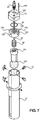
- FIG. 7 shows an exploded view of a second alternate embodiment of the hole boring device.
- FIG. 8 shows a perspective view of a second alternate embodiment of the hole boring device.
- FIG. 9 shows a perspective view of one embodiment of the hole boring device in use.
- the present invention provides a hole boring device 10 configured to bore holes into the earth using pressurized water.
- the hole boring device 10 comprises an elongated cylindrical housing 15 including a proximal end 20 having an inlet 25 , an open distal end 30 , a bore 35 extending through a longitudinal length of the housing 15 from the proximal end 20 to the open distal end 30 , and a spraying device 40 disposed within the bore 35 .
- the diameter of the housing 15 can vary depending on the purpose for which the hole is being bored.
- the housing 15 may have a diameter within a range of one to two inches for boring holes for small flower bulbs, a diameter within a range of two to four inches for planting larger flower bulbs or small plants, or a diameter within a range of four to ten inches for planting larger plants and small trees.
- the hole boring device 10 includes a slot 45 in communication with the bore 35 that extends along the longitudinal length of the housing 15 .
- the slot 45 is configured to provide egress for mud and debris that accumulates in the bore 35 while utilizing the hole boring device 10 to bore holes in the ground.
- the slot 45 allows debris entering the bore 35 during the hole boring process to translate from the bore 35 through the slot 45 and out of the housing 15 .
- the slot 45 includes a longitudinal length less than the longitudinal length of the housing 15 and is disposed between the proximal end 20 and open distal end 30 such that the slot 45 is coterminous with neither the proximal end 20 nor the open distal end 30 .
- a cover 50 is fastened to the proximal end 20 of the housing 15 .
- the cover 50 includes a central aperture 32 through which the inlet 25 extends, as shown in FIG. 3 .
- the inlet 25 is configured to receive a connection from a pressurized water source, such as a power washer or pressurized washer.
- the cover 50 seals the bore 35 at the proximal end 20 such that no fluid or debris can exit through the proximal end 20 during the hole boring process.
- the cover 50 includes a diameter less than a diameter of the bore 35 , such that the cover 50 is configured to be inserted into the bore 35 at the proximal end 20 in order to block or seal the proximal end 20 of the housing 15 .
- the cover can be secured within the bore 35 via a threaded connection therewith.
- an upper surface of the cover 50 is flush with an upper edge of the proximal end 20 of the housing 15 .
- the cover 50 can be recessed into the proximal end 20 of the housing 15 or extend upwardly therefrom.
- the cover 50 includes one or more fasteners 55 configured to removably secure to one or more apertures 58 disposed annularly around the cover 50 so as to removably secure the cover 50 within the proximal end 20 of the housing 15 , as shown in FIG. 3 .
- the inlet 25 comprises a male quick disconnect inlet 28 threadably coupled the central cover aperture 32 , which includes a female threaded bore configured for removably attaching and interchanging the inlet 25 in order to facilitate compatibility with a variety of pressurized washers, as shown in FIG. 3 .
- the male quick disconnect inlet 28 is integral to the cover 50 and may be molded or machined from a single piece of material.
- the inlet 25 is integral to the cover aperture 38 so as to be permanently affixed to within the cover 50 .
- the inlet 25 can include a female quick disconnect inlet.
- the spraying device 40 is secured within the interior of the bore 35 .
- the spraying device 40 is secured to an interior surface 52 of the cover 50 .
- the spraying device 40 includes a nipple 60 in fluid communication with the inlet 25 , such that the nipple 60 can receive water therein when the inlet 25 is coupled to a pressurized water source.
- the nipple 60 is threadably coupled to a lower end of the central cover opening 32 .
- the spraying device 40 is orientated vertically downwardly towards the open distal end 30 of the housing 15 , such that the spraying device 40 sprays a stream of water downwardly out through the open distal end 30 when a pressurized water source is connected to the inlet 25 .
- the spraying device 40 includes internal components that rotate to create a revolving fluid stream, such that the stream is rotatably discharged from the spraying device.
- the revolving fluid stream punctures a ground surface and bores a hole therein.
- the revolving fluid stream covers a larger or wider area than a linear stream of water, thereby optimizing boring.
- the housing 15 restricts the lateral reach of the revolving fluid stream of the spraying device 40 , such that the diameter of the bore 35 defines the area in which the spraying device 40 ejects water.
- the size of a hole bored by the hole boring device 10 is dependent upon the size of the diameter of the bore 35 .
- the hole boring device 10 can include larger housings including bores of larger diameters, which allows the hole boring device 10 to bore wider holes.
- the spraying device 40 includes a rotary nozzle with internal components that are configured to rotate to create a revolving fluid stream.
- alternate embodiments of the invention may include different types of spraying devices 40 .
- the present invention utilizes multiple spraying devices 40 such that there are a plurality of nozzles each configured to rotatably discharge a stream of water passing therethrough.
- the spraying device 40 includes a rotating spray ball apparatus including a shaft having a ball rotatably coupled to an end thereof.
- the spraying device 40 can also be coupled to a motor configured to rotate the spraying device 40 in order to form the revolving boring stream.
- An adjustable depth collar 65 is disposed annularly around the housing 15 and is slidable along the longitudinal length thereof, such that a user may adjust the position of the depth collar 65 .
- the position of the depth collar 65 defines the depth to which the hole boring device 10 may bore, because the lower end of the depth collar 65 contacts the ground and prevents further insertion of the housing 15 into the ground.
- the depth collar 65 includes a circular outer perimeter. However, as long as the inner perimeter of the depth collar 65 is circular such that it can receive the housing 15 , the shape of the outer perimeter of the depth collar 65 can vary.
- the depth collar 65 includes a plurality of collar apertures disposed on an outer side of the collar 65 , and each collar aperture is configured to receive a set screw 70 .
- the set screws 70 secure the collar in a desired position along the housing 15 .
- the housing 15 or the depth collar 65 may include markings, grooves, or detents that allow the depth collar 65 to be positioned precisely about the housing 15 , such that the depth collar 65 is unable to rotate about the housing 15 .
- the hole boring device utilizes multiple spraying devices 40 .
- the spraying devices 40 are orientated vertically downwardly towards the open distal end 30 of the housing 15 , such that the spraying devices 40 simultaneously discharge a stream of water downwardly out through the open distal end 30 when a pressurized water source is connected to the inlet 25 .
- the spraying devices 40 can be configured to rotate or spin as the stream of water passes therethrough, such that multiple streams are rotatably discharged from the spraying device.
- the cover 50 in the shown embodiment includes a planar perimeter portion 52 disposed annularly about a central face 51 that is offset from the perimeter portion 52 .
- the spraying devices 40 each include a nipple 60 in fluid communication with the inlet 25 , such that the nipples 60 can receive water when the inlet 25 is coupled to a pressurized water source.
- the nipples 60 can each be connected to a manifold that distributes water equally from the inlet 25 to the nipples 60 .
- the shown embodiment further includes a variation on the slot that allows debris to exit the housing 15 . As shown, the slot includes an upper slot 35 A and a lower slot 35 B separated by a transverse member 350 that extends across opposing sides of the slot. The transverse member 350 provides additional structural strength to the housing 15 .
- the hole boring device 10 utilizes a motor to rotatably discharge water during the hole boring process.
- the hole boring device includes a motor including a motor housing 75 having a central opening through which the inlet 25 extends, and a shaft 90 extending downward from the motor housing 75 .
- the motor housing 75 includes a plurality of fastening apertures 165 extending downward therethrough, and the upper end of the cover 150 includes a plurality of corresponding fastener apertures 159 , such that a fastener 160 inserted through each fastener aperture 159 secures the motor housing 75 to the cover 150 .
- the cover 150 includes a central aperture through which the shaft 90 extends.
- the cover 150 further includes a plurality of water apertures 155 disposed annularly about the central aperture, which are in fluid communication with the inlet 25 .
- the cover 150 includes one or more fasteners 70 configured and one or more apertures 158 disposed annularly around the cover 150 .
- the fasteners 70 are insertable through corresponding apertures on the housing 15 so as to removably secure to one or more apertures 158 disposed annularly around the cover 150 , securing the cover 150 within the housing 15 .
- the cover further includes a channel having an O-ring 80 therein. The O-ring 80 creates a watertight seal between the motor housing 75 and the cover 150 .
- the spraying device is a rotary spray ball 140 , which includes an inlet 145 configured to receive a connection to a pressurized water source, wherein the inlet 145 is in fluid communication with the water apertures 155 of the cover 150 .
- a nipple 60 connects the cover 150 to the rotary spray ball and allows water to flow thereto.
- the rotary spray ball 140 is operably connected to the shaft 90 , such that actuation of the motor causes the shaft 90 and the coupled rotary spray ball 140 to rotate, forming a rotating discharge stream of water that exits through a plurality of outlets on the rotary spray ball 140 and out of the open distal end of the housing 15 .
- the shown embodiment also includes the slot extending along the longitudinal length of the housing 15 which allows debris entering the bore to exit therethrough during the boring process.
- the motor can be powered by an internal power source, such as a battery.
- FIG. 7 there is shown a view of the hydraulic hole boring device in use.
- the shown embodiment of the hydraulic hole boring device is contemplated for individual use, in that a user may connected the hydraulic hole boring device to a common pressurized water source, such as a power washer 202 , via a connecting hose 203 .
- a common pressurized water source such as a power washer 202
- a connecting hose 203 can include a connection to a larger pressurized water source, such as a large tank mounted to the back of a truck or tractor.
- the length of connecting hose 203 can vary, and a spool or reel can be utilized if there exists a large distance between the hole boring site and the pressurized water source.
- a user 201 may position the depth collar 65 at a point along the housing 15 corresponding to a desired boring depth, and then connect the hole boring device 10 to a pressurized water source, which is shown as a power washer 202 in the illustrated embodiment.
- the power washer 202 includes a connecting hose 203 that connects to a handle 204 , which includes controls for selectively activating or deactivating the pressurized water spray.
- An extension 205 extends from the handle and includes a coupler 206 configured to connect to the inlet of the hole boring device 10 .
- the user After connecting to the power washer 202 , the user then places the open distal end of the housing 15 perpendicularly above or against a ground surface and activates the power washer. Once the power washer is activated, the spraying device rotatably discharges pressurized water vertically downward through the ground surface, thereby forming a revolving, boring stream that bores a hole in the ground surface. The user applies a downward force to the hole boring device 10 via the handle 204 of the power washer 204 , causing the housing 15 to enter the ground until the depth collar 65 makes contact with the perimeter edge of the bored hole, or the surface immediately adjacent the perimeter edge of the bored hole.
- the hole boring device 10 can be utilized to quickly and easily bore a hole of a desired depth via a rotating, pressurized water stream. Additionally, since water is being used to bore the hole, the present invention provides initial watering of the plant or bulb, thereby simultaneously completing the two tasks of hole drilling and initial watering.
- a liquid fertilizer tank may be operably coupled to the pressurized water source, such that liquid fertilizer is mixed into the pressurized water stream that bores the hole. In this way, an individual can bore a hole, provide initial watering for the plant or bulb, and fertilize the plant or bulb with a single device.
Landscapes
- Engineering & Computer Science (AREA)
- Life Sciences & Earth Sciences (AREA)
- Geology (AREA)
- Mining & Mineral Resources (AREA)
- Physics & Mathematics (AREA)
- Environmental & Geological Engineering (AREA)
- Fluid Mechanics (AREA)
- General Life Sciences & Earth Sciences (AREA)
- Geochemistry & Mineralogy (AREA)
- Mechanical Engineering (AREA)
- Nozzles (AREA)
Abstract
Description
Claims (8)
Priority Applications (1)
| Application Number | Priority Date | Filing Date | Title |
|---|---|---|---|
| US15/865,873 US10961783B2 (en) | 2017-07-24 | 2018-01-09 | Hole boring device |
Applications Claiming Priority (2)
| Application Number | Priority Date | Filing Date | Title |
|---|---|---|---|
| US201762536017P | 2017-07-24 | 2017-07-24 | |
| US15/865,873 US10961783B2 (en) | 2017-07-24 | 2018-01-09 | Hole boring device |
Publications (2)
| Publication Number | Publication Date |
|---|---|
| US20190024458A1 US20190024458A1 (en) | 2019-01-24 |
| US10961783B2 true US10961783B2 (en) | 2021-03-30 |
Family
ID=65018722
Family Applications (1)
| Application Number | Title | Priority Date | Filing Date |
|---|---|---|---|
| US15/865,873 Active 2038-04-10 US10961783B2 (en) | 2017-07-24 | 2018-01-09 | Hole boring device |
Country Status (1)
| Country | Link |
|---|---|
| US (1) | US10961783B2 (en) |
Families Citing this family (2)
| Publication number | Priority date | Publication date | Assignee | Title |
|---|---|---|---|---|
| USD964826S1 (en) * | 2022-02-22 | 2022-09-27 | Jiarong Wang | Hand auger |
| US12366120B2 (en) * | 2022-12-19 | 2025-07-22 | Vermeer Manufacturing Company | Handheld water drill and method |
Citations (17)
| Publication number | Priority date | Publication date | Assignee | Title |
|---|---|---|---|---|
| US629539A (en) * | 1898-07-11 | 1899-07-25 | Alexander H Bertram | Boring and excavating implement. |
| US3053331A (en) * | 1959-10-23 | 1962-09-11 | Gale C Corley | Excavating device |
| US3123163A (en) * | 1964-03-03 | Device for soil samples | ||
| US3273930A (en) * | 1964-07-13 | 1966-09-20 | Adam P Gottfried | Soil-extracting implements |
| US3638741A (en) | 1970-03-09 | 1972-02-01 | Joseph P Zizak | Post hole borer |
| US4787465A (en) * | 1986-04-18 | 1988-11-29 | Ben Wade Oakes Dickinson Iii Et Al. | Hydraulic drilling apparatus and method |
| US4986373A (en) | 1989-10-16 | 1991-01-22 | Les Industries L.T.A. Inc./L.T.A. Industries Inc. | Post hole digger |
| US6196337B1 (en) | 1998-04-27 | 2001-03-06 | Jared A. Sikes | Water pressure post-hole digger |
| US6470605B1 (en) * | 1999-11-16 | 2002-10-29 | John William Gilman | Earth reduction tool |
| US6564880B2 (en) | 2000-05-01 | 2003-05-20 | Williams Die & Mold, Inc. | Manually-operated, water-powered digging tool |
| US20080110629A1 (en) * | 2001-11-07 | 2008-05-15 | David Belew | Internally rotating nozzle for facilitating drilling through a subterranean formation |
| US20100060022A1 (en) | 2006-10-06 | 2010-03-11 | Nicholas Alcov | Garden tool for making holes |
| US8500095B1 (en) | 2011-05-17 | 2013-08-06 | Jose D. Salcedo | Electric floor jack device |
| US20140054092A1 (en) * | 2012-08-24 | 2014-02-27 | Buckman Jet Drilling, Inc. | Rotary jet bit for jet drilling and cleaning |
| US8944187B1 (en) | 2011-08-15 | 2015-02-03 | Corbas Marketing, Inc. | Vacuum assisted post hole digger tool and apparatus with rotary clog breaker |
| US20160145944A1 (en) | 2014-11-24 | 2016-05-26 | Jacob Andrew Reed | Water Post Hole Digging Tool |
| US10385537B1 (en) * | 2016-11-29 | 2019-08-20 | William Titus Nelson | Vacuum-assisted hole digger |
-
2018
- 2018-01-09 US US15/865,873 patent/US10961783B2/en active Active
Patent Citations (17)
| Publication number | Priority date | Publication date | Assignee | Title |
|---|---|---|---|---|
| US3123163A (en) * | 1964-03-03 | Device for soil samples | ||
| US629539A (en) * | 1898-07-11 | 1899-07-25 | Alexander H Bertram | Boring and excavating implement. |
| US3053331A (en) * | 1959-10-23 | 1962-09-11 | Gale C Corley | Excavating device |
| US3273930A (en) * | 1964-07-13 | 1966-09-20 | Adam P Gottfried | Soil-extracting implements |
| US3638741A (en) | 1970-03-09 | 1972-02-01 | Joseph P Zizak | Post hole borer |
| US4787465A (en) * | 1986-04-18 | 1988-11-29 | Ben Wade Oakes Dickinson Iii Et Al. | Hydraulic drilling apparatus and method |
| US4986373A (en) | 1989-10-16 | 1991-01-22 | Les Industries L.T.A. Inc./L.T.A. Industries Inc. | Post hole digger |
| US6196337B1 (en) | 1998-04-27 | 2001-03-06 | Jared A. Sikes | Water pressure post-hole digger |
| US6470605B1 (en) * | 1999-11-16 | 2002-10-29 | John William Gilman | Earth reduction tool |
| US6564880B2 (en) | 2000-05-01 | 2003-05-20 | Williams Die & Mold, Inc. | Manually-operated, water-powered digging tool |
| US20080110629A1 (en) * | 2001-11-07 | 2008-05-15 | David Belew | Internally rotating nozzle for facilitating drilling through a subterranean formation |
| US20100060022A1 (en) | 2006-10-06 | 2010-03-11 | Nicholas Alcov | Garden tool for making holes |
| US8500095B1 (en) | 2011-05-17 | 2013-08-06 | Jose D. Salcedo | Electric floor jack device |
| US8944187B1 (en) | 2011-08-15 | 2015-02-03 | Corbas Marketing, Inc. | Vacuum assisted post hole digger tool and apparatus with rotary clog breaker |
| US20140054092A1 (en) * | 2012-08-24 | 2014-02-27 | Buckman Jet Drilling, Inc. | Rotary jet bit for jet drilling and cleaning |
| US20160145944A1 (en) | 2014-11-24 | 2016-05-26 | Jacob Andrew Reed | Water Post Hole Digging Tool |
| US10385537B1 (en) * | 2016-11-29 | 2019-08-20 | William Titus Nelson | Vacuum-assisted hole digger |
Also Published As
| Publication number | Publication date |
|---|---|
| US20190024458A1 (en) | 2019-01-24 |
Similar Documents
| Publication | Publication Date | Title |
|---|---|---|
| US3966233A (en) | Irrigation apparatus | |
| US3783804A (en) | Sub-surface root fertilizer and probe | |
| US4017958A (en) | Irrigation apparatus | |
| CN101472467B (en) | tree irrigation system | |
| US8132362B2 (en) | Plant watering systems | |
| US20170021486A1 (en) | Multi-Functional Garden Tool | |
| US4697952A (en) | Underground irrigation apparatus and method for using same | |
| US3361363A (en) | Watering device | |
| US10961783B2 (en) | Hole boring device | |
| US20170042079A1 (en) | Multi-function modular soil cavity creator tool | |
| US7066403B2 (en) | Sprinkling system and method | |
| KR100853020B1 (en) | Herbicide and pesticide spreader with automatic angle control | |
| JP3677262B2 (en) | Watering nozzle for house-grown crops | |
| US5361849A (en) | Hand tool for use with a water supply | |
| US4170948A (en) | Apparatus for injecting fluid in soil | |
| KR20220124887A (en) | Under Ground Drip-watering Apparatus | |
| US6443367B1 (en) | Deepwatering device | |
| CN205361712U (en) | Spray gun is irrigated to handheld T type that can reconcile | |
| US20070274783A1 (en) | Irrigation device and method | |
| CN107493745A (en) | A kind of Longan Orchard fertilizer apparatus | |
| KR101052269B1 (en) | Sprinkler | |
| CN219741445U (en) | Municipal garden afforestation is with water conservation drip irrigation device | |
| US20160145944A1 (en) | Water Post Hole Digging Tool | |
| US4254717A (en) | Gardening implement for irrigation | |
| KR200282125Y1 (en) | A branching device of a water feeding hose for agriculture |
Legal Events
| Date | Code | Title | Description |
|---|---|---|---|
| FEPP | Fee payment procedure |
Free format text: ENTITY STATUS SET TO UNDISCOUNTED (ORIGINAL EVENT CODE: BIG.); ENTITY STATUS OF PATENT OWNER: MICROENTITY |
|
| FEPP | Fee payment procedure |
Free format text: ENTITY STATUS SET TO SMALL (ORIGINAL EVENT CODE: SMAL); ENTITY STATUS OF PATENT OWNER: MICROENTITY |
|
| STPP | Information on status: patent application and granting procedure in general |
Free format text: DOCKETED NEW CASE - READY FOR EXAMINATION |
|
| STPP | Information on status: patent application and granting procedure in general |
Free format text: NON FINAL ACTION MAILED |
|
| STPP | Information on status: patent application and granting procedure in general |
Free format text: NON FINAL ACTION MAILED |
|
| STPP | Information on status: patent application and granting procedure in general |
Free format text: FINAL REJECTION MAILED |
|
| STPP | Information on status: patent application and granting procedure in general |
Free format text: DOCKETED NEW CASE - READY FOR EXAMINATION |
|
| FEPP | Fee payment procedure |
Free format text: ENTITY STATUS SET TO MICRO (ORIGINAL EVENT CODE: MICR); ENTITY STATUS OF PATENT OWNER: MICROENTITY |
|
| STPP | Information on status: patent application and granting procedure in general |
Free format text: PUBLICATIONS -- ISSUE FEE PAYMENT VERIFIED |
|
| STCF | Information on status: patent grant |
Free format text: PATENTED CASE |
|
| MAFP | Maintenance fee payment |
Free format text: PAYMENT OF MAINTENANCE FEE, 4TH YEAR, MICRO ENTITY (ORIGINAL EVENT CODE: M3551); ENTITY STATUS OF PATENT OWNER: MICROENTITY Year of fee payment: 4 |