US10961381B2 - Composition, film, near infrared cut filter, solid image pickup element, image display device, and infrared sensor - Google Patents
Composition, film, near infrared cut filter, solid image pickup element, image display device, and infrared sensor Download PDFInfo
- Publication number
- US10961381B2 US10961381B2 US16/523,108 US201916523108A US10961381B2 US 10961381 B2 US10961381 B2 US 10961381B2 US 201916523108 A US201916523108 A US 201916523108A US 10961381 B2 US10961381 B2 US 10961381B2
- Authority
- US
- United States
- Prior art keywords
- compound
- group
- composition according
- near infrared
- preferable
- Prior art date
- Legal status (The legal status is an assumption and is not a legal conclusion. Google has not performed a legal analysis and makes no representation as to the accuracy of the status listed.)
- Active
Links
- 239000000203 mixture Substances 0.000 title claims abstract description 180
- 239000007787 solid Substances 0.000 title claims abstract description 50
- 150000001875 compounds Chemical class 0.000 claims abstract description 244
- 229940126062 Compound A Drugs 0.000 claims abstract description 110
- NLDMNSXOCDLTTB-UHFFFAOYSA-N Heterophylliin A Natural products O1C2COC(=O)C3=CC(O)=C(O)C(O)=C3C3=C(O)C(O)=C(O)C=C3C(=O)OC2C(OC(=O)C=2C=C(O)C(O)=C(O)C=2)C(O)C1OC(=O)C1=CC(O)=C(O)C(O)=C1 NLDMNSXOCDLTTB-UHFFFAOYSA-N 0.000 claims abstract description 110
- 125000003118 aryl group Chemical group 0.000 claims abstract description 32
- 125000002950 monocyclic group Chemical group 0.000 claims abstract description 10
- -1 cinnamoyl group Chemical group 0.000 claims description 131
- 239000002253 acid Substances 0.000 claims description 65
- 239000000463 material Substances 0.000 claims description 52
- 125000000217 alkyl group Chemical group 0.000 claims description 50
- 125000005647 linker group Chemical group 0.000 claims description 37
- 238000004040 coloring Methods 0.000 claims description 30
- 125000004435 hydrogen atom Chemical group [H]* 0.000 claims description 30
- 125000003647 acryloyl group Chemical group O=C([*])C([H])=C([H])[H] 0.000 claims description 20
- 230000005540 biological transmission Effects 0.000 claims description 15
- 229920000728 polyester Polymers 0.000 claims description 13
- 239000004721 Polyphenylene oxide Substances 0.000 claims description 11
- 229920000570 polyether Polymers 0.000 claims description 11
- 125000003011 styrenyl group Chemical group [H]\C(*)=C(/[H])C1=C([H])C([H])=C([H])C([H])=C1[H] 0.000 claims description 8
- 125000005439 maleimidyl group Chemical group C1(C=CC(N1*)=O)=O 0.000 claims description 6
- 229920002635 polyurethane Polymers 0.000 claims description 5
- 239000004814 polyurethane Substances 0.000 claims description 5
- 239000004952 Polyamide Substances 0.000 claims description 4
- 229920002396 Polyurea Polymers 0.000 claims description 4
- 229920002647 polyamide Polymers 0.000 claims description 4
- 230000002123 temporal effect Effects 0.000 abstract description 11
- 239000010408 film Substances 0.000 description 104
- 229920005989 resin Polymers 0.000 description 93
- 239000011347 resin Substances 0.000 description 93
- 239000003086 colorant Substances 0.000 description 86
- 239000000049 pigment Substances 0.000 description 72
- 0 *C1=C2C(=C(*)N([4*])/C2=C(/[2*])[3*])/C(=C(\[2*])[3*])N1[4*] Chemical compound *C1=C2C(=C(*)N([4*])/C2=C(/[2*])[3*])/C(=C(\[2*])[3*])N1[4*] 0.000 description 58
- 238000000034 method Methods 0.000 description 55
- 239000006185 dispersion Substances 0.000 description 45
- LLHKCFNBLRBOGN-UHFFFAOYSA-N propylene glycol methyl ether acetate Chemical compound COCC(C)OC(C)=O LLHKCFNBLRBOGN-UHFFFAOYSA-N 0.000 description 43
- 125000004432 carbon atom Chemical group C* 0.000 description 39
- 125000001424 substituent group Chemical group 0.000 description 39
- 239000004094 surface-active agent Substances 0.000 description 39
- 239000002270 dispersing agent Substances 0.000 description 37
- 125000002947 alkylene group Chemical group 0.000 description 34
- NIXOWILDQLNWCW-UHFFFAOYSA-M Acrylate Chemical compound [O-]C(=O)C=C NIXOWILDQLNWCW-UHFFFAOYSA-M 0.000 description 32
- 239000002245 particle Substances 0.000 description 32
- RGDBWNSTHICEOA-UHFFFAOYSA-N C=CC(=O)OCCCCOCC(O)CC(C)C Chemical compound C=CC(=O)OCCCCOCC(O)CC(C)C RGDBWNSTHICEOA-UHFFFAOYSA-N 0.000 description 29
- 239000003999 initiator Substances 0.000 description 27
- 229910052731 fluorine Inorganic materials 0.000 description 26
- 239000002904 solvent Substances 0.000 description 26
- 239000000038 blue colorant Substances 0.000 description 24
- 239000001062 red colorant Substances 0.000 description 24
- 238000010521 absorption reaction Methods 0.000 description 20
- 239000011737 fluorine Substances 0.000 description 20
- YCKRFDGAMUMZLT-UHFFFAOYSA-N Fluorine atom Chemical compound [F] YCKRFDGAMUMZLT-UHFFFAOYSA-N 0.000 description 19
- 239000001060 yellow colorant Substances 0.000 description 19
- XUIMIQQOPSSXEZ-UHFFFAOYSA-N Silicon Chemical compound [Si] XUIMIQQOPSSXEZ-UHFFFAOYSA-N 0.000 description 18
- 239000011324 bead Substances 0.000 description 18
- 125000001072 heteroaryl group Chemical group 0.000 description 18
- 229910052710 silicon Inorganic materials 0.000 description 18
- WGTYBPLFGIVFAS-UHFFFAOYSA-M tetramethylammonium hydroxide Chemical compound [OH-].C[N+](C)(C)C WGTYBPLFGIVFAS-UHFFFAOYSA-M 0.000 description 18
- 239000010703 silicon Substances 0.000 description 17
- 239000003963 antioxidant agent Substances 0.000 description 16
- 239000000975 dye Substances 0.000 description 16
- 229920000642 polymer Polymers 0.000 description 16
- OKKJLVBELUTLKV-UHFFFAOYSA-N Methanol Chemical compound OC OKKJLVBELUTLKV-UHFFFAOYSA-N 0.000 description 15
- HEMHJVSKTPXQMS-UHFFFAOYSA-M Sodium hydroxide Chemical compound [OH-].[Na+] HEMHJVSKTPXQMS-UHFFFAOYSA-M 0.000 description 15
- 239000006096 absorbing agent Substances 0.000 description 15
- 239000000243 solution Substances 0.000 description 15
- WYURNTSHIVDZCO-UHFFFAOYSA-N Tetrahydrofuran Chemical compound C1CCOC1 WYURNTSHIVDZCO-UHFFFAOYSA-N 0.000 description 14
- MCMNRKCIXSYSNV-UHFFFAOYSA-N Zirconium dioxide Chemical compound O=[Zr]=O MCMNRKCIXSYSNV-UHFFFAOYSA-N 0.000 description 14
- 125000003545 alkoxy group Chemical group 0.000 description 14
- 238000002834 transmittance Methods 0.000 description 14
- CERQOIWHTDAKMF-UHFFFAOYSA-N Methacrylic acid Chemical compound CC(=C)C(O)=O CERQOIWHTDAKMF-UHFFFAOYSA-N 0.000 description 13
- 230000002378 acidificating effect Effects 0.000 description 13
- 230000003078 antioxidant effect Effects 0.000 description 13
- 229920001577 copolymer Polymers 0.000 description 13
- 238000011161 development Methods 0.000 description 13
- 239000000040 green colorant Substances 0.000 description 13
- 239000000178 monomer Substances 0.000 description 13
- 239000000758 substrate Substances 0.000 description 13
- 239000007864 aqueous solution Substances 0.000 description 12
- 239000010949 copper Substances 0.000 description 12
- RYGMFSIKBFXOCR-UHFFFAOYSA-N Copper Chemical compound [Cu] RYGMFSIKBFXOCR-UHFFFAOYSA-N 0.000 description 11
- PEDCQBHIVMGVHV-UHFFFAOYSA-N Glycerine Chemical compound OCC(O)CO PEDCQBHIVMGVHV-UHFFFAOYSA-N 0.000 description 11
- 239000004743 Polypropylene Substances 0.000 description 11
- 239000006087 Silane Coupling Agent Substances 0.000 description 11
- 125000005529 alkyleneoxy group Chemical group 0.000 description 11
- 229910052802 copper Inorganic materials 0.000 description 11
- 239000011521 glass Substances 0.000 description 11
- 238000005259 measurement Methods 0.000 description 11
- 229920001155 polypropylene Polymers 0.000 description 11
- 239000006097 ultraviolet radiation absorber Substances 0.000 description 11
- XLYOFNOQVPJJNP-UHFFFAOYSA-N water Substances O XLYOFNOQVPJJNP-UHFFFAOYSA-N 0.000 description 11
- QJSVNKIPOUUEFJ-UHFFFAOYSA-N C=C(C)C(=O)OCC(O)CC(C)C Chemical compound C=C(C)C(=O)OCC(O)CC(C)C QJSVNKIPOUUEFJ-UHFFFAOYSA-N 0.000 description 10
- HEDRZPFGACZZDS-UHFFFAOYSA-N Chloroform Chemical compound ClC(Cl)Cl HEDRZPFGACZZDS-UHFFFAOYSA-N 0.000 description 10
- 125000003178 carboxy group Chemical group [H]OC(*)=O 0.000 description 10
- 230000000052 comparative effect Effects 0.000 description 10
- 239000011259 mixed solution Substances 0.000 description 10
- 239000003960 organic solvent Substances 0.000 description 10
- 238000006116 polymerization reaction Methods 0.000 description 10
- 230000008569 process Effects 0.000 description 10
- 239000012321 sodium triacetoxyborohydride Substances 0.000 description 10
- 230000003595 spectral effect Effects 0.000 description 10
- 239000000126 substance Substances 0.000 description 10
- SIIJSBMBUVIYIB-UHFFFAOYSA-N CCCCC(CC)COC(=O)CCCCOC(=O)CCCCOC(=O)CCCCOC(=O)CCCCCOC(=O)CCCCCOC(=O)CCCCCOC(=O)CCCCCOC(=O)CCCCCOC(=O)CCCCCOC(=O)CCCCCOC(=O)CCCCCOC(=O)CCCCCOC(=O)CCCCCOC(=O)CCCCCOC(=O)CCCCCOC(=O)CCCCCOC(=O)CCCCCOC(=O)CCCCCOC(=O)CCCCCOC(=O)CCCCCOC(=O)CCCOC(=O)C(C)(C)CC Chemical compound CCCCC(CC)COC(=O)CCCCOC(=O)CCCCOC(=O)CCCCOC(=O)CCCCCOC(=O)CCCCCOC(=O)CCCCCOC(=O)CCCCCOC(=O)CCCCCOC(=O)CCCCCOC(=O)CCCCCOC(=O)CCCCCOC(=O)CCCCCOC(=O)CCCCCOC(=O)CCCCCOC(=O)CCCCCOC(=O)CCCCCOC(=O)CCCCCOC(=O)CCCCCOC(=O)CCCCCOC(=O)CCCCCOC(=O)CCCOC(=O)C(C)(C)CC SIIJSBMBUVIYIB-UHFFFAOYSA-N 0.000 description 9
- 125000000732 arylene group Chemical group 0.000 description 9
- 238000000576 coating method Methods 0.000 description 9
- 238000001914 filtration Methods 0.000 description 9
- 125000002887 hydroxy group Chemical group [H]O* 0.000 description 9
- 125000002496 methyl group Chemical group [H]C([H])([H])* 0.000 description 9
- 125000004433 nitrogen atom Chemical group N* 0.000 description 9
- 239000011148 porous material Substances 0.000 description 9
- 238000002835 absorbance Methods 0.000 description 8
- 125000004122 cyclic group Chemical group 0.000 description 8
- 239000003822 epoxy resin Substances 0.000 description 8
- 239000003112 inhibitor Substances 0.000 description 8
- 229920001778 nylon Polymers 0.000 description 8
- 229910052760 oxygen Inorganic materials 0.000 description 8
- 239000001301 oxygen Substances 0.000 description 8
- 125000001997 phenyl group Chemical group [H]C1=C([H])C([H])=C(*)C([H])=C1[H] 0.000 description 8
- 229920000647 polyepoxide Polymers 0.000 description 8
- SLHYNQZXECIZIR-UHFFFAOYSA-N CCC(=O)OCCCCCC(=O)OCCCCCC(=O)OC(C)C Chemical compound CCC(=O)OCCCCCC(=O)OCCCCCC(=O)OC(C)C SLHYNQZXECIZIR-UHFFFAOYSA-N 0.000 description 7
- 239000004677 Nylon Substances 0.000 description 7
- QTZGTEWNAIPHMT-UHFFFAOYSA-N [H]OC(=O)CCCCCOC(=O)CCCCCOC(=O)CC Chemical compound [H]OC(=O)CCCCCOC(=O)CCCCCOC(=O)CC QTZGTEWNAIPHMT-UHFFFAOYSA-N 0.000 description 7
- 125000001153 fluoro group Chemical group F* 0.000 description 7
- 125000000524 functional group Chemical group 0.000 description 7
- 229910052757 nitrogen Inorganic materials 0.000 description 7
- 239000002994 raw material Substances 0.000 description 7
- YLQBMQCUIZJEEH-UHFFFAOYSA-N tetrahydrofuran Natural products C=1C=COC=1 YLQBMQCUIZJEEH-UHFFFAOYSA-N 0.000 description 7
- YSZWOQXIJDPYOS-UHFFFAOYSA-N CCC(C)(C)C(=O)OCCOC(=O)CCC(=O)O Chemical compound CCC(C)(C)C(=O)OCCOC(=O)CCC(=O)O YSZWOQXIJDPYOS-UHFFFAOYSA-N 0.000 description 6
- RIEAVRZEWYXNJJ-UHFFFAOYSA-N CCC(C)(C)C(=O)OCCOC(=O)CCC(=O)OC(C)C Chemical compound CCC(C)(C)C(=O)OCCOC(=O)CCC(=O)OC(C)C RIEAVRZEWYXNJJ-UHFFFAOYSA-N 0.000 description 6
- XEKOWRVHYACXOJ-UHFFFAOYSA-N Ethyl acetate Chemical compound CCOC(C)=O XEKOWRVHYACXOJ-UHFFFAOYSA-N 0.000 description 6
- 239000004793 Polystyrene Substances 0.000 description 6
- KWYUFKZDYYNOTN-UHFFFAOYSA-M Potassium hydroxide Chemical compound [OH-].[K+] KWYUFKZDYYNOTN-UHFFFAOYSA-M 0.000 description 6
- QVGXLLKOCUKJST-UHFFFAOYSA-N atomic oxygen Chemical compound [O] QVGXLLKOCUKJST-UHFFFAOYSA-N 0.000 description 6
- 239000011248 coating agent Substances 0.000 description 6
- 238000009826 distribution Methods 0.000 description 6
- 230000000694 effects Effects 0.000 description 6
- 238000005516 engineering process Methods 0.000 description 6
- 238000004128 high performance liquid chromatography Methods 0.000 description 6
- 239000004973 liquid crystal related substance Substances 0.000 description 6
- 229910052751 metal Inorganic materials 0.000 description 6
- 239000002184 metal Substances 0.000 description 6
- 229910044991 metal oxide Inorganic materials 0.000 description 6
- 150000004706 metal oxides Chemical class 0.000 description 6
- 125000000449 nitro group Chemical group [O-][N+](*)=O 0.000 description 6
- 229920002223 polystyrene Polymers 0.000 description 6
- 150000003839 salts Chemical class 0.000 description 6
- 238000004528 spin coating Methods 0.000 description 6
- PAPBSGBWRJIAAV-UHFFFAOYSA-N ε-Caprolactone Chemical group O=C1CCCCCO1 PAPBSGBWRJIAAV-UHFFFAOYSA-N 0.000 description 6
- NIXOWILDQLNWCW-UHFFFAOYSA-N 2-Propenoic acid Natural products OC(=O)C=C NIXOWILDQLNWCW-UHFFFAOYSA-N 0.000 description 5
- TXBCBTDQIULDIA-UHFFFAOYSA-N 2-[[3-hydroxy-2,2-bis(hydroxymethyl)propoxy]methyl]-2-(hydroxymethyl)propane-1,3-diol Chemical compound OCC(CO)(CO)COCC(CO)(CO)CO TXBCBTDQIULDIA-UHFFFAOYSA-N 0.000 description 5
- 125000003903 2-propenyl group Chemical group [H]C([*])([H])C([H])=C([H])[H] 0.000 description 5
- RXUSAYISDZTCBS-UHFFFAOYSA-N CCCCC(CC)COC(=O)CCCCCOC(=O)CCCOC(=O)C(C)(C)CC Chemical compound CCCCC(CC)COC(=O)CCCCCOC(=O)CCCOC(=O)C(C)(C)CC RXUSAYISDZTCBS-UHFFFAOYSA-N 0.000 description 5
- IAYPIBMASNFSPL-UHFFFAOYSA-N Ethylene oxide Chemical compound C1CO1 IAYPIBMASNFSPL-UHFFFAOYSA-N 0.000 description 5
- XLOMVQKBTHCTTD-UHFFFAOYSA-N Zinc monoxide Chemical compound [Zn]=O XLOMVQKBTHCTTD-UHFFFAOYSA-N 0.000 description 5
- 239000003513 alkali Substances 0.000 description 5
- 239000001055 blue pigment Substances 0.000 description 5
- 125000003700 epoxy group Chemical group 0.000 description 5
- 238000005227 gel permeation chromatography Methods 0.000 description 5
- 229920000578 graft copolymer Polymers 0.000 description 5
- 239000007788 liquid Substances 0.000 description 5
- 230000007246 mechanism Effects 0.000 description 5
- 125000005394 methallyl group Chemical group 0.000 description 5
- 229920005672 polyolefin resin Polymers 0.000 description 5
- 239000001054 red pigment Substances 0.000 description 5
- 238000003860 storage Methods 0.000 description 5
- 125000000020 sulfo group Chemical group O=S(=O)([*])O[H] 0.000 description 5
- 125000000391 vinyl group Chemical group [H]C([*])=C([H])[H] 0.000 description 5
- ICEVOCKVSVLENL-UHFFFAOYSA-N CCC(=O)OCCOC(=O)C1CCCCC1C(=O)O Chemical compound CCC(=O)OCCOC(=O)C1CCCCC1C(=O)O ICEVOCKVSVLENL-UHFFFAOYSA-N 0.000 description 4
- JBMLUGDIVKAVBA-UHFFFAOYSA-N CCC(=O)OCCOC(=O)C1CCCCC1C(=O)OC(C)C Chemical compound CCC(=O)OCCOC(=O)C1CCCCC1C(=O)OC(C)C JBMLUGDIVKAVBA-UHFFFAOYSA-N 0.000 description 4
- IFXOVLPCCCBNHR-UHFFFAOYSA-N CCCCC(CC)COC(=O)CCCCOC(=O)CCCCCOC(=O)CCCOC(=O)C(C)(C)CC Chemical compound CCCCC(CC)COC(=O)CCCCOC(=O)CCCCCOC(=O)CCCOC(=O)C(C)(C)CC IFXOVLPCCCBNHR-UHFFFAOYSA-N 0.000 description 4
- RTZKZFJDLAIYFH-UHFFFAOYSA-N Diethyl ether Chemical compound CCOCC RTZKZFJDLAIYFH-UHFFFAOYSA-N 0.000 description 4
- IAZDPXIOMUYVGZ-UHFFFAOYSA-N Dimethylsulphoxide Chemical compound CS(C)=O IAZDPXIOMUYVGZ-UHFFFAOYSA-N 0.000 description 4
- VYPSYNLAJGMNEJ-UHFFFAOYSA-N Silicium dioxide Chemical compound O=[Si]=O VYPSYNLAJGMNEJ-UHFFFAOYSA-N 0.000 description 4
- PPBRXRYQALVLMV-UHFFFAOYSA-N Styrene Chemical compound C=CC1=CC=CC=C1 PPBRXRYQALVLMV-UHFFFAOYSA-N 0.000 description 4
- GWEVSGVZZGPLCZ-UHFFFAOYSA-N Titan oxide Chemical compound O=[Ti]=O GWEVSGVZZGPLCZ-UHFFFAOYSA-N 0.000 description 4
- 238000000862 absorption spectrum Methods 0.000 description 4
- 125000003342 alkenyl group Chemical group 0.000 description 4
- 125000004429 atom Chemical group 0.000 description 4
- 239000000987 azo dye Substances 0.000 description 4
- IOJUPLGTWVMSFF-UHFFFAOYSA-N benzothiazole Chemical group C1=CC=C2SC=NC2=C1 IOJUPLGTWVMSFF-UHFFFAOYSA-N 0.000 description 4
- 125000001797 benzyl group Chemical group [H]C1=C([H])C([H])=C(C([H])=C1[H])C([H])([H])* 0.000 description 4
- 238000006243 chemical reaction Methods 0.000 description 4
- 239000003795 chemical substances by application Substances 0.000 description 4
- 230000000295 complement effect Effects 0.000 description 4
- XCJYREBRNVKWGJ-UHFFFAOYSA-N copper(II) phthalocyanine Chemical compound [Cu+2].C12=CC=CC=C2C(N=C2[N-]C(C3=CC=CC=C32)=N2)=NC1=NC([C]1C=CC=CC1=1)=NC=1N=C1[C]3C=CC=CC3=C2[N-]1 XCJYREBRNVKWGJ-UHFFFAOYSA-N 0.000 description 4
- 238000001723 curing Methods 0.000 description 4
- 125000004093 cyano group Chemical group *C#N 0.000 description 4
- JHIVVAPYMSGYDF-UHFFFAOYSA-N cyclohexanone Chemical compound O=C1CCCCC1 JHIVVAPYMSGYDF-UHFFFAOYSA-N 0.000 description 4
- 238000011156 evaluation Methods 0.000 description 4
- 235000011187 glycerol Nutrition 0.000 description 4
- 239000001056 green pigment Substances 0.000 description 4
- 125000005843 halogen group Chemical group 0.000 description 4
- 239000001023 inorganic pigment Substances 0.000 description 4
- 238000004519 manufacturing process Methods 0.000 description 4
- NWVVVBRKAWDGAB-UHFFFAOYSA-N p-methoxyphenol Chemical compound COC1=CC=C(O)C=C1 NWVVVBRKAWDGAB-UHFFFAOYSA-N 0.000 description 4
- CSHWQDPOILHKBI-UHFFFAOYSA-N peryrene Natural products C1=CC(C2=CC=CC=3C2=C2C=CC=3)=C3C2=CC=CC3=C1 CSHWQDPOILHKBI-UHFFFAOYSA-N 0.000 description 4
- ISWSIDIOOBJBQZ-UHFFFAOYSA-N phenol group Chemical group C1(=CC=CC=C1)O ISWSIDIOOBJBQZ-UHFFFAOYSA-N 0.000 description 4
- 125000000843 phenylene group Chemical group C1(=C(C=CC=C1)*)* 0.000 description 4
- 125000002467 phosphate group Chemical group [H]OP(=O)(O[H])O[*] 0.000 description 4
- 238000002360 preparation method Methods 0.000 description 4
- 238000007639 printing Methods 0.000 description 4
- 239000011163 secondary particle Substances 0.000 description 4
- 239000004065 semiconductor Substances 0.000 description 4
- XOLBLPGZBRYERU-UHFFFAOYSA-N tin dioxide Chemical compound O=[Sn]=O XOLBLPGZBRYERU-UHFFFAOYSA-N 0.000 description 4
- 238000012546 transfer Methods 0.000 description 4
- VCGRFBXVSFAGGA-UHFFFAOYSA-N (1,1-dioxo-1,4-thiazinan-4-yl)-[6-[[3-(4-fluorophenyl)-5-methyl-1,2-oxazol-4-yl]methoxy]pyridin-3-yl]methanone Chemical compound CC=1ON=C(C=2C=CC(F)=CC=2)C=1COC(N=C1)=CC=C1C(=O)N1CCS(=O)(=O)CC1 VCGRFBXVSFAGGA-UHFFFAOYSA-N 0.000 description 3
- WFOVEDJTASPCIR-UHFFFAOYSA-N 3-[(4-methyl-5-pyridin-4-yl-1,2,4-triazol-3-yl)methylamino]-n-[[2-(trifluoromethyl)phenyl]methyl]benzamide Chemical compound N=1N=C(C=2C=CN=CC=2)N(C)C=1CNC(C=1)=CC=CC=1C(=O)NCC1=CC=CC=C1C(F)(F)F WFOVEDJTASPCIR-UHFFFAOYSA-N 0.000 description 3
- CYJRNFFLTBEQSQ-UHFFFAOYSA-N 8-(3-methyl-1-benzothiophen-5-yl)-N-(4-methylsulfonylpyridin-3-yl)quinoxalin-6-amine Chemical compound CS(=O)(=O)C1=C(C=NC=C1)NC=1C=C2N=CC=NC2=C(C=1)C=1C=CC2=C(C(=CS2)C)C=1 CYJRNFFLTBEQSQ-UHFFFAOYSA-N 0.000 description 3
- RZVAJINKPMORJF-UHFFFAOYSA-N Acetaminophen Chemical compound CC(=O)NC1=CC=C(O)C=C1 RZVAJINKPMORJF-UHFFFAOYSA-N 0.000 description 3
- UHOVQNZJYSORNB-UHFFFAOYSA-N Benzene Chemical compound C1=CC=CC=C1 UHOVQNZJYSORNB-UHFFFAOYSA-N 0.000 description 3
- JBXMVSFLLGHQTG-UHFFFAOYSA-N C.C.CCC(C)C Chemical compound C.C.CCC(C)C JBXMVSFLLGHQTG-UHFFFAOYSA-N 0.000 description 3
- ZVYGIPWYVVJFRW-UHFFFAOYSA-N C=CC(=O)OCCC(C)C Chemical compound C=CC(=O)OCCC(C)C ZVYGIPWYVVJFRW-UHFFFAOYSA-N 0.000 description 3
- XBELICPWDLHPCY-UHFFFAOYSA-N CCC(=O)OCCCCOC1=CC=C(C(=O)O)C=C1 Chemical compound CCC(=O)OCCCCOC1=CC=C(C(=O)O)C=C1 XBELICPWDLHPCY-UHFFFAOYSA-N 0.000 description 3
- GBWMJHMYFGMRGP-UHFFFAOYSA-N CCC(=O)OCCCCOC1=CC=C(C(=O)OC(C)C)C=C1 Chemical compound CCC(=O)OCCCCOC1=CC=C(C(=O)OC(C)C)C=C1 GBWMJHMYFGMRGP-UHFFFAOYSA-N 0.000 description 3
- MSWWWDBGCLIUEX-UHFFFAOYSA-N CCC(C)(C)C(=O)NCCCCCCCCCCCC(=O)O Chemical compound CCC(C)(C)C(=O)NCCCCCCCCCCCC(=O)O MSWWWDBGCLIUEX-UHFFFAOYSA-N 0.000 description 3
- PBFLHWOXFZOVEG-UHFFFAOYSA-N CCC(C)(C)C(=O)NCCCCCCCCCCCC(=O)OC(C)C Chemical compound CCC(C)(C)C(=O)NCCCCCCCCCCCC(=O)OC(C)C PBFLHWOXFZOVEG-UHFFFAOYSA-N 0.000 description 3
- VUAXHMVRKOTJKP-UHFFFAOYSA-N CCC(C)(C)C(=O)O Chemical compound CCC(C)(C)C(=O)O VUAXHMVRKOTJKP-UHFFFAOYSA-N 0.000 description 3
- BSQKFTUIWLMBMZ-UHFFFAOYSA-N CCC(C)(C)C(=O)OC(C)C Chemical compound CCC(C)(C)C(=O)OC(C)C BSQKFTUIWLMBMZ-UHFFFAOYSA-N 0.000 description 3
- DQDFETZHWCCCAO-UHFFFAOYSA-N CCC(C)(C)C(=O)OCCOC(=O)C1=CC=CC=C1C(=O)O Chemical compound CCC(C)(C)C(=O)OCCOC(=O)C1=CC=CC=C1C(=O)O DQDFETZHWCCCAO-UHFFFAOYSA-N 0.000 description 3
- MYQZPPRBMMSGHN-UHFFFAOYSA-N CCC(C)(C)C(=O)OCCOC(=O)C1=CC=CC=C1C(=O)OC(C)C Chemical compound CCC(C)(C)C(=O)OCCOC(=O)C1=CC=CC=C1C(=O)OC(C)C MYQZPPRBMMSGHN-UHFFFAOYSA-N 0.000 description 3
- IOSCOEJTHLFPBI-UHFFFAOYSA-N CCC(C)C(=O)OCCC(=O)O Chemical compound CCC(C)C(=O)OCCC(=O)O IOSCOEJTHLFPBI-UHFFFAOYSA-N 0.000 description 3
- OBKYGRIKYKJBJM-UHFFFAOYSA-N CCC(C)C(=O)OCCC(=O)OC(C)C Chemical compound CCC(C)C(=O)OCCC(=O)OC(C)C OBKYGRIKYKJBJM-UHFFFAOYSA-N 0.000 description 3
- YZJFVRPYXCCAOS-UHFFFAOYSA-N CCCCC(CC)COC(=O)CCCCCOC(=O)CCCOC(=O)C(C)C Chemical compound CCCCC(CC)COC(=O)CCCCCOC(=O)CCCOC(=O)C(C)C YZJFVRPYXCCAOS-UHFFFAOYSA-N 0.000 description 3
- GESMMGMFHKHOHT-UHFFFAOYSA-N CCCCC(CC)COC(=O)CCCCOC(=O)CCCCCOC(=O)CCCOC(=O)C(C)C Chemical compound CCCCC(CC)COC(=O)CCCCOC(=O)CCCCCOC(=O)CCCOC(=O)C(C)C GESMMGMFHKHOHT-UHFFFAOYSA-N 0.000 description 3
- CAROHPKTBVJXGI-UHFFFAOYSA-N CCCCC(CC)COC(=O)COC(=O)COC(=O)COC(=O)CCCCCOC(=O)CCCCCOC(=O)CCCCCOC(=O)CCCCCOC(=O)CCCCCOC(=O)CCCCCOC(=O)CCCCCOC(=O)CCCCCOC(=O)CCCCCOC(=O)CCCCCOC(=O)CCCCCOC(=O)CCCCCOC(=O)CCCCCOC(=O)CCCCCOC(=O)CCCCCOC(=O)CCCCCOC(=O)CCCCCOC(=O)CCCOC(=O)C(C)C Chemical compound CCCCC(CC)COC(=O)COC(=O)COC(=O)COC(=O)CCCCCOC(=O)CCCCCOC(=O)CCCCCOC(=O)CCCCCOC(=O)CCCCCOC(=O)CCCCCOC(=O)CCCCCOC(=O)CCCCCOC(=O)CCCCCOC(=O)CCCCCOC(=O)CCCCCOC(=O)CCCCCOC(=O)CCCCCOC(=O)CCCCCOC(=O)CCCCCOC(=O)CCCCCOC(=O)CCCCCOC(=O)CCCOC(=O)C(C)C CAROHPKTBVJXGI-UHFFFAOYSA-N 0.000 description 3
- YMWUJEATGCHHMB-UHFFFAOYSA-N Dichloromethane Chemical compound ClCCl YMWUJEATGCHHMB-UHFFFAOYSA-N 0.000 description 3
- AYCPARAPKDAOEN-LJQANCHMSA-N N-[(1S)-2-(dimethylamino)-1-phenylethyl]-6,6-dimethyl-3-[(2-methyl-4-thieno[3,2-d]pyrimidinyl)amino]-1,4-dihydropyrrolo[3,4-c]pyrazole-5-carboxamide Chemical compound C1([C@H](NC(=O)N2C(C=3NN=C(NC=4C=5SC=CC=5N=C(C)N=4)C=3C2)(C)C)CN(C)C)=CC=CC=C1 AYCPARAPKDAOEN-LJQANCHMSA-N 0.000 description 3
- PXHVJJICTQNCMI-UHFFFAOYSA-N Nickel Chemical compound [Ni] PXHVJJICTQNCMI-UHFFFAOYSA-N 0.000 description 3
- CDBYLPFSWZWCQE-UHFFFAOYSA-L Sodium Carbonate Chemical compound [Na+].[Na+].[O-]C([O-])=O CDBYLPFSWZWCQE-UHFFFAOYSA-L 0.000 description 3
- YXFVVABEGXRONW-UHFFFAOYSA-N Toluene Chemical compound CC1=CC=CC=C1 YXFVVABEGXRONW-UHFFFAOYSA-N 0.000 description 3
- ZMANZCXQSJIPKH-UHFFFAOYSA-N Triethylamine Chemical compound CCN(CC)CC ZMANZCXQSJIPKH-UHFFFAOYSA-N 0.000 description 3
- MPIAGWXWVAHQBB-UHFFFAOYSA-N [3-prop-2-enoyloxy-2-[[3-prop-2-enoyloxy-2,2-bis(prop-2-enoyloxymethyl)propoxy]methyl]-2-(prop-2-enoyloxymethyl)propyl] prop-2-enoate Chemical compound C=CC(=O)OCC(COC(=O)C=C)(COC(=O)C=C)COCC(COC(=O)C=C)(COC(=O)C=C)COC(=O)C=C MPIAGWXWVAHQBB-UHFFFAOYSA-N 0.000 description 3
- 125000005012 alkyl thioether group Chemical group 0.000 description 3
- 125000000304 alkynyl group Chemical group 0.000 description 3
- 125000003277 amino group Chemical group 0.000 description 3
- 125000003710 aryl alkyl group Chemical group 0.000 description 3
- 150000004832 aryl thioethers Chemical group 0.000 description 3
- 125000004104 aryloxy group Chemical group 0.000 description 3
- AOJOEFVRHOZDFN-UHFFFAOYSA-N benzyl 2-methylprop-2-enoate Chemical compound CC(=C)C(=O)OCC1=CC=CC=C1 AOJOEFVRHOZDFN-UHFFFAOYSA-N 0.000 description 3
- 150000001768 cations Chemical class 0.000 description 3
- 239000000539 dimer Substances 0.000 description 3
- 150000002170 ethers Chemical class 0.000 description 3
- 125000001495 ethyl group Chemical group [H]C([H])([H])C([H])([H])* 0.000 description 3
- 125000003983 fluorenyl group Chemical group C1(=CC=CC=2C3=CC=CC=C3CC12)* 0.000 description 3
- 125000005553 heteroaryloxy group Chemical group 0.000 description 3
- 238000003384 imaging method Methods 0.000 description 3
- 230000003993 interaction Effects 0.000 description 3
- 239000002736 nonionic surfactant Substances 0.000 description 3
- 239000012860 organic pigment Substances 0.000 description 3
- 239000003973 paint Substances 0.000 description 3
- 238000000206 photolithography Methods 0.000 description 3
- 239000004810 polytetrafluoroethylene Substances 0.000 description 3
- 229920001343 polytetrafluoroethylene Polymers 0.000 description 3
- 230000001681 protective effect Effects 0.000 description 3
- 238000010298 pulverizing process Methods 0.000 description 3
- RQGPLDBZHMVWCH-UHFFFAOYSA-N pyrrolo[3,2-b]pyrrole Chemical compound C1=NC2=CC=NC2=C1 RQGPLDBZHMVWCH-UHFFFAOYSA-N 0.000 description 3
- 239000004576 sand Substances 0.000 description 3
- 230000035945 sensitivity Effects 0.000 description 3
- XGVXKJKTISMIOW-ZDUSSCGKSA-N simurosertib Chemical compound N1N=CC(C=2SC=3C(=O)NC(=NC=3C=2)[C@H]2N3CCC(CC3)C2)=C1C XGVXKJKTISMIOW-ZDUSSCGKSA-N 0.000 description 3
- 238000001228 spectrum Methods 0.000 description 3
- 238000012360 testing method Methods 0.000 description 3
- 230000008719 thickening Effects 0.000 description 3
- 238000004448 titration Methods 0.000 description 3
- 229910001930 tungsten oxide Inorganic materials 0.000 description 3
- JYEUMXHLPRZUAT-UHFFFAOYSA-N 1,2,3-triazine Chemical group C1=CN=NN=C1 JYEUMXHLPRZUAT-UHFFFAOYSA-N 0.000 description 2
- SMZOUWXMTYCWNB-UHFFFAOYSA-N 2-(2-methoxy-5-methylphenyl)ethanamine Chemical compound COC1=CC=C(C)C=C1CCN SMZOUWXMTYCWNB-UHFFFAOYSA-N 0.000 description 2
- UHFFVFAKEGKNAQ-UHFFFAOYSA-N 2-benzyl-2-(dimethylamino)-1-(4-morpholin-4-ylphenyl)butan-1-one Chemical compound C=1C=C(N2CCOCC2)C=CC=1C(=O)C(CC)(N(C)C)CC1=CC=CC=C1 UHFFVFAKEGKNAQ-UHFFFAOYSA-N 0.000 description 2
- 125000000954 2-hydroxyethyl group Chemical group [H]C([*])([H])C([H])([H])O[H] 0.000 description 2
- FIHBHSQYSYVZQE-UHFFFAOYSA-N 6-prop-2-enoyloxyhexyl prop-2-enoate Chemical compound C=CC(=O)OCCCCCCOC(=O)C=C FIHBHSQYSYVZQE-UHFFFAOYSA-N 0.000 description 2
- KJRGSZODFARSJE-UHFFFAOYSA-N CCC(C)C(=O)OCCCCCC(=O)OC(C)C Chemical compound CCC(C)C(=O)OCCCCCC(=O)OC(C)C KJRGSZODFARSJE-UHFFFAOYSA-N 0.000 description 2
- QVGLDPPIMKSVBG-UHFFFAOYSA-N CCC(C)C.CCC(C)C Chemical compound CCC(C)C.CCC(C)C QVGLDPPIMKSVBG-UHFFFAOYSA-N 0.000 description 2
- IBQOAURRWRJEFU-UHFFFAOYSA-N CCCCC(CC)COC(=O)CCCCCOC(=O)CCCCCOC(=O)CCCCCOC(=O)CCCCCOC(=O)CCCCCOC(=O)CCCCCOC(=O)CCCCCOC(=O)CCCCCOC(=O)CCCCCOC(=O)CCCOC(=O)C(C)(C)CC Chemical compound CCCCC(CC)COC(=O)CCCCCOC(=O)CCCCCOC(=O)CCCCCOC(=O)CCCCCOC(=O)CCCCCOC(=O)CCCCCOC(=O)CCCCCOC(=O)CCCCCOC(=O)CCCCCOC(=O)CCCOC(=O)C(C)(C)CC IBQOAURRWRJEFU-UHFFFAOYSA-N 0.000 description 2
- ZARUZTHKDIYRNF-UHFFFAOYSA-N CCCCC(CC)COC(=O)COC(=O)CCCCCOC(=O)CCCOC(=O)C(C)C Chemical compound CCCCC(CC)COC(=O)COC(=O)CCCCCOC(=O)CCCOC(=O)C(C)C ZARUZTHKDIYRNF-UHFFFAOYSA-N 0.000 description 2
- QUSNBJAOOMFDIB-UHFFFAOYSA-N Ethylamine Chemical compound CCN QUSNBJAOOMFDIB-UHFFFAOYSA-N 0.000 description 2
- YNQLUTRBYVCPMQ-UHFFFAOYSA-N Ethylbenzene Chemical compound CCC1=CC=CC=C1 YNQLUTRBYVCPMQ-UHFFFAOYSA-N 0.000 description 2
- QIGBRXMKCJKVMJ-UHFFFAOYSA-N Hydroquinone Chemical compound OC1=CC=C(O)C=C1 QIGBRXMKCJKVMJ-UHFFFAOYSA-N 0.000 description 2
- WOBHKFSMXKNTIM-UHFFFAOYSA-N Hydroxyethyl methacrylate Chemical compound CC(=C)C(=O)OCCO WOBHKFSMXKNTIM-UHFFFAOYSA-N 0.000 description 2
- AFVFQIVMOAPDHO-UHFFFAOYSA-N Methanesulfonic acid Chemical compound CS(O)(=O)=O AFVFQIVMOAPDHO-UHFFFAOYSA-N 0.000 description 2
- 238000005481 NMR spectroscopy Methods 0.000 description 2
- 229910019142 PO4 Inorganic materials 0.000 description 2
- NBIIXXVUZAFLBC-UHFFFAOYSA-N Phosphoric acid Chemical compound OP(O)(O)=O NBIIXXVUZAFLBC-UHFFFAOYSA-N 0.000 description 2
- OAICVXFJPJFONN-UHFFFAOYSA-N Phosphorus Chemical compound [P] OAICVXFJPJFONN-UHFFFAOYSA-N 0.000 description 2
- NQRYJNQNLNOLGT-UHFFFAOYSA-N Piperidine Chemical compound C1CCNCC1 NQRYJNQNLNOLGT-UHFFFAOYSA-N 0.000 description 2
- 239000004698 Polyethylene Substances 0.000 description 2
- 239000002202 Polyethylene glycol Substances 0.000 description 2
- OFOBLEOULBTSOW-UHFFFAOYSA-N Propanedioic acid Natural products OC(=O)CC(O)=O OFOBLEOULBTSOW-UHFFFAOYSA-N 0.000 description 2
- KAESVJOAVNADME-UHFFFAOYSA-N Pyrrole Chemical compound C=1C=CNC=1 KAESVJOAVNADME-UHFFFAOYSA-N 0.000 description 2
- NRCMAYZCPIVABH-UHFFFAOYSA-N Quinacridone Chemical compound N1C2=CC=CC=C2C(=O)C2=C1C=C1C(=O)C3=CC=CC=C3NC1=C2 NRCMAYZCPIVABH-UHFFFAOYSA-N 0.000 description 2
- 239000004115 Sodium Silicate Substances 0.000 description 2
- ZJCCRDAZUWHFQH-UHFFFAOYSA-N Trimethylolpropane Chemical compound CCC(CO)(CO)CO ZJCCRDAZUWHFQH-UHFFFAOYSA-N 0.000 description 2
- 238000004220 aggregation Methods 0.000 description 2
- 230000002776 aggregation Effects 0.000 description 2
- 125000004450 alkenylene group Chemical group 0.000 description 2
- 125000000129 anionic group Chemical group 0.000 description 2
- 150000001450 anions Chemical class 0.000 description 2
- PYKYMHQGRFAEBM-UHFFFAOYSA-N anthraquinone Natural products CCC(=O)c1c(O)c2C(=O)C3C(C=CC=C3O)C(=O)c2cc1CC(=O)OC PYKYMHQGRFAEBM-UHFFFAOYSA-N 0.000 description 2
- 150000004945 aromatic hydrocarbons Chemical class 0.000 description 2
- 239000012298 atmosphere Substances 0.000 description 2
- MYONAGGJKCJOBT-UHFFFAOYSA-N benzimidazol-2-one Chemical compound C1=CC=CC2=NC(=O)N=C21 MYONAGGJKCJOBT-UHFFFAOYSA-N 0.000 description 2
- ZYGHJZDHTFUPRJ-UHFFFAOYSA-N benzo-alpha-pyrone Natural products C1=CC=C2OC(=O)C=CC2=C1 ZYGHJZDHTFUPRJ-UHFFFAOYSA-N 0.000 description 2
- 239000012965 benzophenone Substances 0.000 description 2
- 239000012964 benzotriazole Substances 0.000 description 2
- 125000000484 butyl group Chemical group [H]C([*])([H])C([H])([H])C([H])([H])C([H])([H])[H] 0.000 description 2
- 238000004364 calculation method Methods 0.000 description 2
- 238000011088 calibration curve Methods 0.000 description 2
- 150000001721 carbon Chemical group 0.000 description 2
- 229910052799 carbon Inorganic materials 0.000 description 2
- 150000004699 copper complex Chemical class 0.000 description 2
- 229960000956 coumarin Drugs 0.000 description 2
- 235000001671 coumarin Nutrition 0.000 description 2
- 125000006165 cyclic alkyl group Chemical group 0.000 description 2
- BGTOWKSIORTVQH-UHFFFAOYSA-N cyclopentanone Chemical compound O=C1CCCC1 BGTOWKSIORTVQH-UHFFFAOYSA-N 0.000 description 2
- GPLRAVKSCUXZTP-UHFFFAOYSA-N diglycerol Chemical compound OCC(O)COCC(O)CO GPLRAVKSCUXZTP-UHFFFAOYSA-N 0.000 description 2
- 238000004821 distillation Methods 0.000 description 2
- 238000005401 electroluminescence Methods 0.000 description 2
- 238000010894 electron beam technology Methods 0.000 description 2
- 125000006575 electron-withdrawing group Chemical group 0.000 description 2
- 150000002148 esters Chemical class 0.000 description 2
- LZCLXQDLBQLTDK-UHFFFAOYSA-N ethyl 2-hydroxypropanoate Chemical compound CCOC(=O)C(C)O LZCLXQDLBQLTDK-UHFFFAOYSA-N 0.000 description 2
- 239000000945 filler Substances 0.000 description 2
- 239000010931 gold Substances 0.000 description 2
- 238000010438 heat treatment Methods 0.000 description 2
- CATSNJVOTSVZJV-UHFFFAOYSA-N heptan-2-one Chemical compound CCCCCC(C)=O CATSNJVOTSVZJV-UHFFFAOYSA-N 0.000 description 2
- 125000005842 heteroatom Chemical group 0.000 description 2
- 125000000623 heterocyclic group Chemical group 0.000 description 2
- 150000002430 hydrocarbons Chemical group 0.000 description 2
- 230000006872 improvement Effects 0.000 description 2
- 239000012535 impurity Substances 0.000 description 2
- COHYTHOBJLSHDF-UHFFFAOYSA-N indigo powder Natural products N1C2=CC=CC=C2C(=O)C1=C1C(=O)C2=CC=CC=C2N1 COHYTHOBJLSHDF-UHFFFAOYSA-N 0.000 description 2
- 238000002347 injection Methods 0.000 description 2
- 239000007924 injection Substances 0.000 description 2
- 238000005342 ion exchange Methods 0.000 description 2
- 150000002576 ketones Chemical class 0.000 description 2
- 238000005461 lubrication Methods 0.000 description 2
- 239000011976 maleic acid Substances 0.000 description 2
- 239000002923 metal particle Substances 0.000 description 2
- 229920003145 methacrylic acid copolymer Polymers 0.000 description 2
- 125000001434 methanylylidene group Chemical group [H]C#[*] 0.000 description 2
- 238000003801 milling Methods 0.000 description 2
- 238000002156 mixing Methods 0.000 description 2
- 125000001624 naphthyl group Chemical group 0.000 description 2
- 229910052755 nonmetal Inorganic materials 0.000 description 2
- JFNLZVQOOSMTJK-KNVOCYPGSA-N norbornene Chemical compound C1[C@@H]2CC[C@H]1C=C2 JFNLZVQOOSMTJK-KNVOCYPGSA-N 0.000 description 2
- 229920003986 novolac Polymers 0.000 description 2
- 239000003921 oil Substances 0.000 description 2
- 239000011368 organic material Substances 0.000 description 2
- 125000004430 oxygen atom Chemical group O* 0.000 description 2
- 238000005192 partition Methods 0.000 description 2
- 150000002978 peroxides Chemical class 0.000 description 2
- 125000002080 perylenyl group Chemical group C1(=CC=C2C=CC=C3C4=CC=CC5=CC=CC(C1=C23)=C45)* 0.000 description 2
- 229910052698 phosphorus Inorganic materials 0.000 description 2
- 239000011574 phosphorus Substances 0.000 description 2
- 229920003229 poly(methyl methacrylate) Polymers 0.000 description 2
- 229920000573 polyethylene Polymers 0.000 description 2
- 229920001223 polyethylene glycol Polymers 0.000 description 2
- 239000004926 polymethyl methacrylate Substances 0.000 description 2
- WQGWDDDVZFFDIG-UHFFFAOYSA-N pyrogallol Chemical compound OC1=CC=CC(O)=C1O WQGWDDDVZFFDIG-UHFFFAOYSA-N 0.000 description 2
- FYNROBRQIVCIQF-UHFFFAOYSA-N pyrrolo[3,2-b]pyrrole-5,6-dione Chemical compound C1=CN=C2C(=O)C(=O)N=C21 FYNROBRQIVCIQF-UHFFFAOYSA-N 0.000 description 2
- 230000005855 radiation Effects 0.000 description 2
- 230000002829 reductive effect Effects 0.000 description 2
- 150000003377 silicon compounds Chemical class 0.000 description 2
- KSAVQLQVUXSOCR-UHFFFAOYSA-M sodium lauroyl sarcosinate Chemical compound [Na+].CCCCCCCCCCCC(=O)N(C)CC([O-])=O KSAVQLQVUXSOCR-UHFFFAOYSA-M 0.000 description 2
- NTHWMYGWWRZVTN-UHFFFAOYSA-N sodium silicate Chemical compound [Na+].[Na+].[O-][Si]([O-])=O NTHWMYGWWRZVTN-UHFFFAOYSA-N 0.000 description 2
- 229910052911 sodium silicate Inorganic materials 0.000 description 2
- SKRWFPLZQAAQSU-UHFFFAOYSA-N stibanylidynetin;hydrate Chemical compound O.[Sn].[Sb] SKRWFPLZQAAQSU-UHFFFAOYSA-N 0.000 description 2
- 150000005846 sugar alcohols Polymers 0.000 description 2
- 125000004434 sulfur atom Chemical group 0.000 description 2
- VDZOOKBUILJEDG-UHFFFAOYSA-M tetrabutylammonium hydroxide Chemical compound [OH-].CCCC[N+](CCCC)(CCCC)CCCC VDZOOKBUILJEDG-UHFFFAOYSA-M 0.000 description 2
- 125000000101 thioether group Chemical group 0.000 description 2
- VZCYOOQTPOCHFL-UHFFFAOYSA-N trans-butenedioic acid Natural products OC(=O)C=CC(O)=O VZCYOOQTPOCHFL-UHFFFAOYSA-N 0.000 description 2
- QXJQHYBHAIHNGG-UHFFFAOYSA-N trimethylolethane Chemical compound OCC(C)(CO)CO QXJQHYBHAIHNGG-UHFFFAOYSA-N 0.000 description 2
- 229920002554 vinyl polymer Polymers 0.000 description 2
- 239000001052 yellow pigment Substances 0.000 description 2
- 239000011787 zinc oxide Substances 0.000 description 2
- QNODIIQQMGDSEF-UHFFFAOYSA-N (1-hydroxycyclohexyl)-phenylmethanone Chemical compound C=1C=CC=CC=1C(=O)C1(O)CCCCC1 QNODIIQQMGDSEF-UHFFFAOYSA-N 0.000 description 1
- HHQAGBQXOWLTLL-UHFFFAOYSA-N (2-hydroxy-3-phenoxypropyl) prop-2-enoate Chemical compound C=CC(=O)OCC(O)COC1=CC=CC=C1 HHQAGBQXOWLTLL-UHFFFAOYSA-N 0.000 description 1
- STBLNCCBQMHSRC-BATDWUPUSA-N (2s)-n-[(3s,4s)-5-acetyl-7-cyano-4-methyl-1-[(2-methylnaphthalen-1-yl)methyl]-2-oxo-3,4-dihydro-1,5-benzodiazepin-3-yl]-2-(methylamino)propanamide Chemical compound O=C1[C@@H](NC(=O)[C@H](C)NC)[C@H](C)N(C(C)=O)C2=CC(C#N)=CC=C2N1CC1=C(C)C=CC2=CC=CC=C12 STBLNCCBQMHSRC-BATDWUPUSA-N 0.000 description 1
- PGSHZSDDBWTHDU-UHFFFAOYSA-N (3-oxobutan-2-ylideneamino) 4-methylbenzenesulfonate Chemical compound CC(=O)C(C)=NOS(=O)(=O)C1=CC=C(C)C=C1 PGSHZSDDBWTHDU-UHFFFAOYSA-N 0.000 description 1
- MRUDPRFGMHTPFJ-UHFFFAOYSA-N (3-oxobutan-2-ylideneamino) acetate Chemical compound CC(=O)ON=C(C)C(C)=O MRUDPRFGMHTPFJ-UHFFFAOYSA-N 0.000 description 1
- SKCKRZWCOYHBEC-UHFFFAOYSA-N (3-oxobutan-2-ylideneamino) benzoate Chemical compound CC(=O)C(C)=NOC(=O)C1=CC=CC=C1 SKCKRZWCOYHBEC-UHFFFAOYSA-N 0.000 description 1
- JFFCVOSCPLKMLG-UHFFFAOYSA-N (3-oxobutan-2-ylideneamino) propanoate Chemical compound CCC(=O)ON=C(C)C(C)=O JFFCVOSCPLKMLG-UHFFFAOYSA-N 0.000 description 1
- HQLZSJJJXHJANW-UHFFFAOYSA-N (3-oxopentan-2-ylideneamino) acetate Chemical compound CCC(=O)C(C)=NOC(C)=O HQLZSJJJXHJANW-UHFFFAOYSA-N 0.000 description 1
- FFJCNSLCJOQHKM-CLFAGFIQSA-N (z)-1-[(z)-octadec-9-enoxy]octadec-9-ene Chemical compound CCCCCCCC\C=C/CCCCCCCCOCCCCCCCC\C=C/CCCCCCCC FFJCNSLCJOQHKM-CLFAGFIQSA-N 0.000 description 1
- MYWOJODOMFBVCB-UHFFFAOYSA-N 1,2,6-trimethylphenanthrene Chemical compound CC1=CC=C2C3=CC(C)=CC=C3C=CC2=C1C MYWOJODOMFBVCB-UHFFFAOYSA-N 0.000 description 1
- BCMCBBGGLRIHSE-UHFFFAOYSA-N 1,3-benzoxazole Chemical compound C1=CC=C2OC=NC2=C1 BCMCBBGGLRIHSE-UHFFFAOYSA-N 0.000 description 1
- 125000000355 1,3-benzoxazolyl group Chemical group O1C(=NC2=C1C=CC=C2)* 0.000 description 1
- AZQWKYJCGOJGHM-UHFFFAOYSA-N 1,4-benzoquinone Chemical compound O=C1C=CC(=O)C=C1 AZQWKYJCGOJGHM-UHFFFAOYSA-N 0.000 description 1
- BQTPKSBXMONSJI-UHFFFAOYSA-N 1-cyclohexylpyrrole-2,5-dione Chemical compound O=C1C=CC(=O)N1C1CCCCC1 BQTPKSBXMONSJI-UHFFFAOYSA-N 0.000 description 1
- ARXJGSRGQADJSQ-UHFFFAOYSA-N 1-methoxypropan-2-ol Chemical compound COCC(C)O ARXJGSRGQADJSQ-UHFFFAOYSA-N 0.000 description 1
- HIDBROSJWZYGSZ-UHFFFAOYSA-N 1-phenylpyrrole-2,5-dione Chemical compound O=C1C=CC(=O)N1C1=CC=CC=C1 HIDBROSJWZYGSZ-UHFFFAOYSA-N 0.000 description 1
- WJFKNYWRSNBZNX-UHFFFAOYSA-N 10H-phenothiazine Chemical compound C1=CC=C2NC3=CC=CC=C3SC2=C1 WJFKNYWRSNBZNX-UHFFFAOYSA-N 0.000 description 1
- HYZJCKYKOHLVJF-UHFFFAOYSA-N 1H-benzimidazole Chemical compound C1=CC=C2NC=NC2=C1 HYZJCKYKOHLVJF-UHFFFAOYSA-N 0.000 description 1
- KGRVJHAUYBGFFP-UHFFFAOYSA-N 2,2'-Methylenebis(4-methyl-6-tert-butylphenol) Chemical compound CC(C)(C)C1=CC(C)=CC(CC=2C(=C(C=C(C)C=2)C(C)(C)C)O)=C1O KGRVJHAUYBGFFP-UHFFFAOYSA-N 0.000 description 1
- RNFJDJUURJAICM-UHFFFAOYSA-N 2,2,4,4,6,6-hexaphenoxy-1,3,5-triaza-2$l^{5},4$l^{5},6$l^{5}-triphosphacyclohexa-1,3,5-triene Chemical compound N=1P(OC=2C=CC=CC=2)(OC=2C=CC=CC=2)=NP(OC=2C=CC=CC=2)(OC=2C=CC=CC=2)=NP=1(OC=1C=CC=CC=1)OC1=CC=CC=C1 RNFJDJUURJAICM-UHFFFAOYSA-N 0.000 description 1
- GQHTUMJGOHRCHB-UHFFFAOYSA-N 2,3,4,6,7,8,9,10-octahydropyrimido[1,2-a]azepine Chemical compound C1CCCCN2CCCN=C21 GQHTUMJGOHRCHB-UHFFFAOYSA-N 0.000 description 1
- QWQNFXDYOCUEER-UHFFFAOYSA-N 2,3-ditert-butyl-4-methylphenol Chemical compound CC1=CC=C(O)C(C(C)(C)C)=C1C(C)(C)C QWQNFXDYOCUEER-UHFFFAOYSA-N 0.000 description 1
- LXOFYPKXCSULTL-UHFFFAOYSA-N 2,4,7,9-tetramethyldec-5-yne-4,7-diol Chemical compound CC(C)CC(C)(O)C#CC(C)(O)CC(C)C LXOFYPKXCSULTL-UHFFFAOYSA-N 0.000 description 1
- 150000003923 2,5-pyrrolediones Chemical class 0.000 description 1
- XKWGWBPECLWUKL-UHFFFAOYSA-N 2-(1,3,6,8-tetratert-butylbenzo[d][1,3,2]benzodioxaphosphepin-10-yl)oxy-N,N-bis[2-(1,3,6,8-tetratert-butylbenzo[d][1,3,2]benzodioxaphosphepin-10-yl)oxyethyl]ethanamine Chemical compound C(C)(C)(C)C1=CC(=CC2=C1OP(OC1=C2C(=CC(=C1)C(C)(C)C)C(C)(C)C)C(C)(C)C)OCCN(CCOC1=CC2=C(OP(OC3=C2C(=CC(=C3)C(C)(C)C)C(C)(C)C)C(C)(C)C)C(=C1)C(C)(C)C)CCOC1=CC2=C(OP(OC3=C2C(=CC(=C3)C(C)(C)C)C(C)(C)C)C(C)(C)C)C(=C1)C(C)(C)C XKWGWBPECLWUKL-UHFFFAOYSA-N 0.000 description 1
- YAGPRJYCDKGWJR-UHFFFAOYSA-N 2-(2,4,8,10-tetratert-butylbenzo[d][1,3,2]benzodioxaphosphepin-6-yl)oxy-n,n-bis[2-(2,4,8,10-tetratert-butylbenzo[d][1,3,2]benzodioxaphosphepin-6-yl)oxyethyl]ethanamine Chemical compound O1C2=C(C(C)(C)C)C=C(C(C)(C)C)C=C2C2=CC(C(C)(C)C)=CC(C(C)(C)C)=C2OP1OCCN(CCOP1OC2=C(C=C(C=C2C=2C=C(C=C(C=2O1)C(C)(C)C)C(C)(C)C)C(C)(C)C)C(C)(C)C)CCOP(OC1=C(C=C(C=C11)C(C)(C)C)C(C)(C)C)OC2=C1C=C(C(C)(C)C)C=C2C(C)(C)C YAGPRJYCDKGWJR-UHFFFAOYSA-N 0.000 description 1
- GIAFURWZWWWBQT-UHFFFAOYSA-N 2-(2-aminoethoxy)ethanol Chemical compound NCCOCCO GIAFURWZWWWBQT-UHFFFAOYSA-N 0.000 description 1
- VXQBJTKSVGFQOL-UHFFFAOYSA-N 2-(2-butoxyethoxy)ethyl acetate Chemical compound CCCCOCCOCCOC(C)=O VXQBJTKSVGFQOL-UHFFFAOYSA-N 0.000 description 1
- GJKGAPPUXSSCFI-UHFFFAOYSA-N 2-Hydroxy-4'-(2-hydroxyethoxy)-2-methylpropiophenone Chemical compound CC(C)(O)C(=O)C1=CC=C(OCCO)C=C1 GJKGAPPUXSSCFI-UHFFFAOYSA-N 0.000 description 1
- WMYINDVYGQKYMI-UHFFFAOYSA-N 2-[2,2-bis(hydroxymethyl)butoxymethyl]-2-ethylpropane-1,3-diol Chemical compound CCC(CO)(CO)COCC(CC)(CO)CO WMYINDVYGQKYMI-UHFFFAOYSA-N 0.000 description 1
- PTJWCLYPVFJWMP-UHFFFAOYSA-N 2-[[3-hydroxy-2-[[3-hydroxy-2,2-bis(hydroxymethyl)propoxy]methyl]-2-(hydroxymethyl)propoxy]methyl]-2-(hydroxymethyl)propane-1,3-diol Chemical compound OCC(CO)(CO)COCC(CO)(CO)COCC(CO)(CO)CO PTJWCLYPVFJWMP-UHFFFAOYSA-N 0.000 description 1
- ZVUNTIMPQCQCAQ-UHFFFAOYSA-N 2-dodecanoyloxyethyl dodecanoate Chemical compound CCCCCCCCCCCC(=O)OCCOC(=O)CCCCCCCCCCC ZVUNTIMPQCQCAQ-UHFFFAOYSA-N 0.000 description 1
- SVONRAPFKPVNKG-UHFFFAOYSA-N 2-ethoxyethyl acetate Chemical compound CCOCCOC(C)=O SVONRAPFKPVNKG-UHFFFAOYSA-N 0.000 description 1
- PCKZAVNWRLEHIP-UHFFFAOYSA-N 2-hydroxy-1-[4-[[4-(2-hydroxy-2-methylpropanoyl)phenyl]methyl]phenyl]-2-methylpropan-1-one Chemical compound C1=CC(C(=O)C(C)(O)C)=CC=C1CC1=CC=C(C(=O)C(C)(C)O)C=C1 PCKZAVNWRLEHIP-UHFFFAOYSA-N 0.000 description 1
- LWRBVKNFOYUCNP-UHFFFAOYSA-N 2-methyl-1-(4-methylsulfanylphenyl)-2-morpholin-4-ylpropan-1-one Chemical compound C1=CC(SC)=CC=C1C(=O)C(C)(C)N1CCOCC1 LWRBVKNFOYUCNP-UHFFFAOYSA-N 0.000 description 1
- RIWRBSMFKVOJMN-UHFFFAOYSA-N 2-methyl-1-phenylpropan-2-ol Chemical compound CC(C)(O)CC1=CC=CC=C1 RIWRBSMFKVOJMN-UHFFFAOYSA-N 0.000 description 1
- HXIQYSLFEXIOAV-UHFFFAOYSA-N 2-tert-butyl-4-(5-tert-butyl-4-hydroxy-2-methylphenyl)sulfanyl-5-methylphenol Chemical compound CC1=CC(O)=C(C(C)(C)C)C=C1SC1=CC(C(C)(C)C)=C(O)C=C1C HXIQYSLFEXIOAV-UHFFFAOYSA-N 0.000 description 1
- WLXYHLHNIRJAIG-UHFFFAOYSA-N 2h-benzo[e]isoindole Chemical compound C1=CC=C2C3=CNC=C3C=CC2=C1 WLXYHLHNIRJAIG-UHFFFAOYSA-N 0.000 description 1
- XBNVWXKPFORCRI-UHFFFAOYSA-N 2h-naphtho[2,3-f]quinolin-1-one Chemical compound C1=CC=CC2=CC3=C4C(=O)CC=NC4=CC=C3C=C21 XBNVWXKPFORCRI-UHFFFAOYSA-N 0.000 description 1
- AGIJRRREJXSQJR-UHFFFAOYSA-N 2h-thiazine Chemical compound N1SC=CC=C1 AGIJRRREJXSQJR-UHFFFAOYSA-N 0.000 description 1
- DQYSALLXMHVJAV-UHFFFAOYSA-M 3-heptyl-2-[(3-heptyl-4-methyl-1,3-thiazol-3-ium-2-yl)methylidene]-4-methyl-1,3-thiazole;iodide Chemical compound [I-].CCCCCCCN1C(C)=CS\C1=C\C1=[N+](CCCCCCC)C(C)=CS1 DQYSALLXMHVJAV-UHFFFAOYSA-M 0.000 description 1
- JIGUICYYOYEXFS-UHFFFAOYSA-N 3-tert-butylbenzene-1,2-diol Chemical compound CC(C)(C)C1=CC=CC(O)=C1O JIGUICYYOYEXFS-UHFFFAOYSA-N 0.000 description 1
- KWOLFJPFCHCOCG-UHFFFAOYSA-N Acetophenone Natural products CC(=O)C1=CC=CC=C1 KWOLFJPFCHCOCG-UHFFFAOYSA-N 0.000 description 1
- 229920002126 Acrylic acid copolymer Polymers 0.000 description 1
- 239000004925 Acrylic resin Substances 0.000 description 1
- 229920000178 Acrylic resin Polymers 0.000 description 1
- NLHHRLWOUZZQLW-UHFFFAOYSA-N Acrylonitrile Chemical compound C=CC#N NLHHRLWOUZZQLW-UHFFFAOYSA-N 0.000 description 1
- VHUUQVKOLVNVRT-UHFFFAOYSA-N Ammonium hydroxide Chemical compound [NH4+].[OH-] VHUUQVKOLVNVRT-UHFFFAOYSA-N 0.000 description 1
- KYNSBQPICQTCGU-UHFFFAOYSA-N Benzopyrane Chemical compound C1=CC=C2C=CCOC2=C1 KYNSBQPICQTCGU-UHFFFAOYSA-N 0.000 description 1
- DKPFZGUDAPQIHT-UHFFFAOYSA-N Butyl acetate Natural products CCCCOC(C)=O DKPFZGUDAPQIHT-UHFFFAOYSA-N 0.000 description 1
- GNCXKXUAKBLIIH-UHFFFAOYSA-N C.C.C.C.C.C.CCC(=O)OC.CCC(=O)OC.CCCC(=O)C(C)(C)CC.CCOC.COCC(C)=O Chemical compound C.C.C.C.C.C.CCC(=O)OC.CCC(=O)OC.CCCC(=O)C(C)(C)CC.CCOC.COCC(C)=O GNCXKXUAKBLIIH-UHFFFAOYSA-N 0.000 description 1
- ZWEKPRWJGVMSEL-UHFFFAOYSA-N C.C.C.C.CCC(C)C(=O)OCCC#CC#CC#C(F)(F)(F)(F)(F)(F)(F)(F)(F)(F)(F)(F)F.N.N#N.[H]OCCOC(C)COCCOCCOC(=O)C(C)CC.[H]OCCOCC(C)OCCOCCOC(=O)C(C)CC Chemical compound C.C.C.C.CCC(C)C(=O)OCCC#CC#CC#C(F)(F)(F)(F)(F)(F)(F)(F)(F)(F)(F)(F)F.N.N#N.[H]OCCOC(C)COCCOCCOC(=O)C(C)CC.[H]OCCOCC(C)OCCOCCOC(=O)C(C)CC ZWEKPRWJGVMSEL-UHFFFAOYSA-N 0.000 description 1
- JCSKWYSEAPDOJD-UHFFFAOYSA-N C.C.C.C.CCCC(C)(C)C(C)(C)C.CCN(C)CC Chemical compound C.C.C.C.CCCC(C)(C)C(C)(C)C.CCN(C)CC JCSKWYSEAPDOJD-UHFFFAOYSA-N 0.000 description 1
- SOVQEYNAEQSFBX-UHFFFAOYSA-N C.C.CCC(C)C(=O)OCCC#CC#CC#C(F)(F)(F)(F)(F)(F)(F)(F)(F)(F)(F)(F)F.N.N#N.[H]OCCOC(C)COCCOCCOC(=O)C(C)CC.[H]OCCOCC(C)OCCOCCOC(=O)C(C)CC Chemical compound C.C.CCC(C)C(=O)OCCC#CC#CC#C(F)(F)(F)(F)(F)(F)(F)(F)(F)(F)(F)(F)F.N.N#N.[H]OCCOC(C)COCCOCCOC(=O)C(C)CC.[H]OCCOCC(C)OCCOCCOC(=O)C(C)CC SOVQEYNAEQSFBX-UHFFFAOYSA-N 0.000 description 1
- CXOSQCHKEKLLNV-UHFFFAOYSA-N C.C.CCCC(C)(C)C(C)(C)C.CCN(C)CC Chemical compound C.C.CCCC(C)(C)C(C)(C)C.CCN(C)CC CXOSQCHKEKLLNV-UHFFFAOYSA-N 0.000 description 1
- ZXJNWVJEDFLFLV-UHFFFAOYSA-N C.C.[H]OC(=O)CCCCC(C)(C)C(C)(C)C Chemical compound C.C.[H]OC(=O)CCCCC(C)(C)C(C)(C)C ZXJNWVJEDFLFLV-UHFFFAOYSA-N 0.000 description 1
- KHNZLBWXOKRBDA-UHFFFAOYSA-N C=C(C)C(=O)OCC(O)COC(=O)C(C)(C)CC.C=CCOC(=O)C(C)(C)CC.CCC(C)(C)C(=O)O.CCC(C)(C)C(=O)O.CCC(C)(C)C(=O)O.CCC(C)(C)C(=O)O.CCC(C)(C)C(=O)OC.CCC(C)(C)C(=O)OCC1=CC=CC=C1.CCC(C)(C)C(=O)OCC1=CC=CC=C1.CCC(C)(C)C(=O)OCC1=CC=CC=C1.CCC(C)(C)C(=O)OCCO.CCC1(C(=O)OC)COCC(C)(C(=O)OC)C1 Chemical compound C=C(C)C(=O)OCC(O)COC(=O)C(C)(C)CC.C=CCOC(=O)C(C)(C)CC.CCC(C)(C)C(=O)O.CCC(C)(C)C(=O)O.CCC(C)(C)C(=O)O.CCC(C)(C)C(=O)O.CCC(C)(C)C(=O)OC.CCC(C)(C)C(=O)OCC1=CC=CC=C1.CCC(C)(C)C(=O)OCC1=CC=CC=C1.CCC(C)(C)C(=O)OCC1=CC=CC=C1.CCC(C)(C)C(=O)OCCO.CCC1(C(=O)OC)COCC(C)(C(=O)OC)C1 KHNZLBWXOKRBDA-UHFFFAOYSA-N 0.000 description 1
- AFNNDRGSNGTGRF-UHFFFAOYSA-N C=C(C)C(=O)OCC(O)COC(=O)C(C)(C)CC.C=CCOC(=O)C(C)(C)CC.CCC(C)(C)C(=O)O.CCC(C)(C)C(=O)O.CCC(C)(C)C(=O)OC.CCC(C)(C)C(=O)OCC1=CC=CC=C1.CCC1(C(=O)OC)COCC(C)(C(=O)OC)C1 Chemical compound C=C(C)C(=O)OCC(O)COC(=O)C(C)(C)CC.C=CCOC(=O)C(C)(C)CC.CCC(C)(C)C(=O)O.CCC(C)(C)C(=O)O.CCC(C)(C)C(=O)OC.CCC(C)(C)C(=O)OCC1=CC=CC=C1.CCC1(C(=O)OC)COCC(C)(C(=O)OC)C1 AFNNDRGSNGTGRF-UHFFFAOYSA-N 0.000 description 1
- VVIGLUIMHQSEJP-UHFFFAOYSA-N C=C(C)C(=O)OCC(O)COC(=O)C(C)(C)CC.CCC(C)(C)C(=O)O.CCC(C)(C)C(=O)OC.CCC(C)(C)C(=O)OCC1=CC=CC=C1.CCC1(C(=O)OC)COCC(C)(C(=O)OC)C1 Chemical compound C=C(C)C(=O)OCC(O)COC(=O)C(C)(C)CC.CCC(C)(C)C(=O)O.CCC(C)(C)C(=O)OC.CCC(C)(C)C(=O)OCC1=CC=CC=C1.CCC1(C(=O)OC)COCC(C)(C(=O)OC)C1 VVIGLUIMHQSEJP-UHFFFAOYSA-N 0.000 description 1
- HMVDNURLPVIZKD-UHFFFAOYSA-L C=C1C(=O)C(C)=C1[O-].CC1=C([O-])C(C)C1=O.CC1C([O-])C(C)C1[O-] Chemical compound C=C1C(=O)C(C)=C1[O-].CC1=C([O-])C(C)C1=O.CC1C([O-])C(C)C1[O-] HMVDNURLPVIZKD-UHFFFAOYSA-L 0.000 description 1
- WDCLDIHFVMMPSW-UHFFFAOYSA-N C=CC(=O)OCC(CO)(COCC(COC(=O)C=C)(COC(=O)C=C)COC(=O)C=C)COC(=O)C=C.C=CC(=O)OCC(COCC(COC(=O)C=C)(COC(=O)C=C)COC(=O)C=C)(COC(=O)C=C)COC(=O)C=C Chemical compound C=CC(=O)OCC(CO)(COCC(COC(=O)C=C)(COC(=O)C=C)COC(=O)C=C)COC(=O)C=C.C=CC(=O)OCC(COCC(COC(=O)C=C)(COC(=O)C=C)COC(=O)C=C)(COC(=O)C=C)COC(=O)C=C WDCLDIHFVMMPSW-UHFFFAOYSA-N 0.000 description 1
- SWDOQBYUDVUYMB-UHFFFAOYSA-N C=CC(=O)OCC(CO)COC(=O)CCN(C)CCC[Si](C)(OCC)OCC Chemical compound C=CC(=O)OCC(CO)COC(=O)CCN(C)CCC[Si](C)(OCC)OCC SWDOQBYUDVUYMB-UHFFFAOYSA-N 0.000 description 1
- FLAZLNCACVRPPD-UHFFFAOYSA-N C=CC(=O)OCCOCCOCC(COCCOCCOC(=O)C=C)(COCCOCCOC(=O)C=C)COCC(COCCOCCOC(=O)C=C)(COCCOCCOC(=O)C=C)COCCOCCOC(=O)C=C Chemical compound C=CC(=O)OCCOCCOCC(COCCOCCOC(=O)C=C)(COCCOCCOC(=O)C=C)COCC(COCCOCCOC(=O)C=C)(COCCOCCOC(=O)C=C)COCCOCCOC(=O)C=C FLAZLNCACVRPPD-UHFFFAOYSA-N 0.000 description 1
- VTMSSJKVUVVWNJ-UHFFFAOYSA-N C=CC1=CC=C(CC(C)C)C=C1 Chemical compound C=CC1=CC=C(CC(C)C)C=C1 VTMSSJKVUVVWNJ-UHFFFAOYSA-N 0.000 description 1
- COJRVDKEQABQQG-QITYMFBYSA-N CC(=O)O/N=C(C1=CC=CC=C1)/C1=C/C2=C(\C=C/1)C1=CC=C([N+](=O)[O-])C=C1C2(C)C.CC(=O)O/N=C(\C)C1=CC2=C(C=C1)N(CCOC#CC#CC#CC#CC(F)(F)(F)(F)(F)(F)(F)(F)(F)(F)(F)(F)(F)(F)(F)(F)F)C1=CC=C(C(=O)C3=C(C)C=CC=C3)C=C12.CCCCC(CC)CN1C2=CC=C(/C(=N\OC(C)=O)C3=C(OCC(F)(F)C(F)F)C=CC=C3)C=C2C2=CC(C(=O)C3=C(C)C=C(C)C=C3C)=C3C=CC=CC3=C21.CCN1C2=CC=C(C(=O)C3=C(C)C=CC=C3)C=C2C2=C1C=CC1=C2O/C(=N/OC(C)=O)C1=O Chemical compound CC(=O)O/N=C(C1=CC=CC=C1)/C1=C/C2=C(\C=C/1)C1=CC=C([N+](=O)[O-])C=C1C2(C)C.CC(=O)O/N=C(\C)C1=CC2=C(C=C1)N(CCOC#CC#CC#CC#CC(F)(F)(F)(F)(F)(F)(F)(F)(F)(F)(F)(F)(F)(F)(F)(F)F)C1=CC=C(C(=O)C3=C(C)C=CC=C3)C=C12.CCCCC(CC)CN1C2=CC=C(/C(=N\OC(C)=O)C3=C(OCC(F)(F)C(F)F)C=CC=C3)C=C2C2=CC(C(=O)C3=C(C)C=C(C)C=C3C)=C3C=CC=CC3=C21.CCN1C2=CC=C(C(=O)C3=C(C)C=CC=C3)C=C2C2=C1C=CC1=C2O/C(=N/OC(C)=O)C1=O COJRVDKEQABQQG-QITYMFBYSA-N 0.000 description 1
- BRALZLJTCFMTCA-PZJHDQTBSA-N CC(=O)O/N=C(\CCCSC1=CC=C(Cl)C=C1)C1=CC=C(N(C2=CC=CC=C2)C2=CC=C(C(=O)C3=C(C)C=CC=C3)C=C2)C=C1.CC(=O)O/N=C(\CCSC1=CC=C(Cl)C=C1)C(=O)C1=CC=C(SC2=CC=C(C(=O)C3=CC=CC=C3)C=C2)C=C1.CCN1C2=CC=C(C(=O)C3=C(C)C=CC=C3)C=C2C2=CC(/C(CCCSC3=CC=C(Cl)C=C3)=N/OC(=O)C3=CC=CC=C3)=CC=C21.CCN1C2=CC=C(C(=O)C3=C(C)C=CC=C3)C=C2C2=CC(/C(CCCSC3=CC=C(Cl)C=C3)=N/OC(C)=O)=CC=C21.CCN1C2=CC=C(C(=O)C3=C(C)C=CC=C3)C=C2C2=CC(C(=O)/C(CCSC3=CC=C(Cl)C=C3)=N/OC(C)=O)=CC=C21 Chemical compound CC(=O)O/N=C(\CCCSC1=CC=C(Cl)C=C1)C1=CC=C(N(C2=CC=CC=C2)C2=CC=C(C(=O)C3=C(C)C=CC=C3)C=C2)C=C1.CC(=O)O/N=C(\CCSC1=CC=C(Cl)C=C1)C(=O)C1=CC=C(SC2=CC=C(C(=O)C3=CC=CC=C3)C=C2)C=C1.CCN1C2=CC=C(C(=O)C3=C(C)C=CC=C3)C=C2C2=CC(/C(CCCSC3=CC=C(Cl)C=C3)=N/OC(=O)C3=CC=CC=C3)=CC=C21.CCN1C2=CC=C(C(=O)C3=C(C)C=CC=C3)C=C2C2=CC(/C(CCCSC3=CC=C(Cl)C=C3)=N/OC(C)=O)=CC=C21.CCN1C2=CC=C(C(=O)C3=C(C)C=CC=C3)C=C2C2=CC(C(=O)/C(CCSC3=CC=C(Cl)C=C3)=N/OC(C)=O)=CC=C21 BRALZLJTCFMTCA-PZJHDQTBSA-N 0.000 description 1
- KDNXYIDZLMEEPT-RPCXECATSA-N CC(=O)O/N=C1\COC2=C1C1=CC=CC=C1C=C2.CC(C)(C)C(=O)O/N=C(\CCSC1=CC=C(Br)C=C1)C(=O)C1=CC=C(SC2=CC=C(C(=O)C3=CC=CC=C3)C=C2)C=C1.CCCCCC/C(=N/OC(=O)C1=CC=CC=C1)C(=O)C1=CC=C(SC2=CC=CC=C2)C=C1.CCN1C2=CC=C(C(=O)C3=C(C)C=CC=C3)C=C2C2=C1C=CC(/C(C)=N/OC(=O)C(C)(C)N1CCCCC1)=C2.CCN1C2=CC=C(C(=O)C3=C(C)C=CC=C3)C=C2C2=C1C=CC(/C(C)=N/OC(C)=O)=C2 Chemical compound CC(=O)O/N=C1\COC2=C1C1=CC=CC=C1C=C2.CC(C)(C)C(=O)O/N=C(\CCSC1=CC=C(Br)C=C1)C(=O)C1=CC=C(SC2=CC=C(C(=O)C3=CC=CC=C3)C=C2)C=C1.CCCCCC/C(=N/OC(=O)C1=CC=CC=C1)C(=O)C1=CC=C(SC2=CC=CC=C2)C=C1.CCN1C2=CC=C(C(=O)C3=C(C)C=CC=C3)C=C2C2=C1C=CC(/C(C)=N/OC(=O)C(C)(C)N1CCCCC1)=C2.CCN1C2=CC=C(C(=O)C3=C(C)C=CC=C3)C=C2C2=C1C=CC(/C(C)=N/OC(C)=O)=C2 KDNXYIDZLMEEPT-RPCXECATSA-N 0.000 description 1
- AJKILLXGMNCPSX-UHFFFAOYSA-N CC(C)C(=O)OCCOC(=O)C1CCCCC1C(=O)O Chemical compound CC(C)C(=O)OCCOC(=O)C1CCCCC1C(=O)O AJKILLXGMNCPSX-UHFFFAOYSA-N 0.000 description 1
- GKWTWIVDYGMTBR-UHFFFAOYSA-N CC(C)CCN1C(=O)C=CC1=O Chemical compound CC(C)CCN1C(=O)C=CC1=O GKWTWIVDYGMTBR-UHFFFAOYSA-N 0.000 description 1
- WKJZVAZULDAEAB-QLRMJJMVSA-N CC(C)OC(=O)C(=C/C=C1\OCC(C)(C)N1C)C(=O)OC(C)C.CCCCCCCCOC(=O)/C(=C/C=C/N(CC)CC)CC1=CC=CC=C1.COC1=CC=C(C(=O)CC(=O)C2=CC=C(C(C)(C)C)C=C2)C=C1 Chemical compound CC(C)OC(=O)C(=C/C=C1\OCC(C)(C)N1C)C(=O)OC(C)C.CCCCCCCCOC(=O)/C(=C/C=C/N(CC)CC)CC1=CC=CC=C1.COC1=CC=C(C(=O)CC(=O)C2=CC=C(C(C)(C)C)C=C2)C=C1 WKJZVAZULDAEAB-QLRMJJMVSA-N 0.000 description 1
- DCAKVJQXOBKZGI-FUFZTOQCSA-N CC(C)OC(=O)C(=C/C=C1\OCC(C)(C)N1C)C(=O)OC(C)C.COC1=CC=C(C(=O)CC(=O)C2=CC=C(C(C)(C)C)C=C2)C=C1 Chemical compound CC(C)OC(=O)C(=C/C=C1\OCC(C)(C)N1C)C(=O)OC(C)C.COC1=CC=C(C(=O)CC(=O)C2=CC=C(C(C)(C)C)C=C2)C=C1 DCAKVJQXOBKZGI-FUFZTOQCSA-N 0.000 description 1
- GVPIPXYXECJGDZ-UHFFFAOYSA-N CC(C)OC(=O)C1CCCCC1C(=O)OCCOC(=O)C(C)C Chemical compound CC(C)OC(=O)C1CCCCC1C(=O)OCCOC(=O)C(C)C GVPIPXYXECJGDZ-UHFFFAOYSA-N 0.000 description 1
- YUJLFACJQUHQTP-UHFFFAOYSA-N CC1C([O-])C(C)C1[O-] Chemical compound CC1C([O-])C(C)C1[O-] YUJLFACJQUHQTP-UHFFFAOYSA-N 0.000 description 1
- ABLJXAKOEYXZGP-UHFFFAOYSA-N CCC(=O)OC.CCC(=O)OC.CCCC(=O)C(C)(C)CC.CCOC.COCC(C)=O Chemical compound CCC(=O)OC.CCC(=O)OC.CCCC(=O)C(C)(C)CC.CCOC.COCC(C)=O ABLJXAKOEYXZGP-UHFFFAOYSA-N 0.000 description 1
- WBTWIHROROXLAJ-UHFFFAOYSA-N CCC(C)(C)C(=O)O.CCC(C)(C)C(=O)OCC1=CC=CC=C1.CCC(C)(C)C(=O)OCCO Chemical compound CCC(C)(C)C(=O)O.CCC(C)(C)C(=O)OCC1=CC=CC=C1.CCC(C)(C)C(=O)OCCO WBTWIHROROXLAJ-UHFFFAOYSA-N 0.000 description 1
- KABADROPKJAAFZ-UHFFFAOYSA-N CCC(C)(C)C(=O)O.CCC(C)(C)C(=O)OCCCCCC(=O)O.CCC(C)(C)C(=O)OCCN(C)C.CCCCC(CC)COC(=O)CCCCCOC(=O)CCCOC(=O)C(C)(C)CC.CCCCC(CC)COC(=O)CCCCCOC(=O)CCCOC(=O)C(C)(C)CC Chemical compound CCC(C)(C)C(=O)O.CCC(C)(C)C(=O)OCCCCCC(=O)O.CCC(C)(C)C(=O)OCCN(C)C.CCCCC(CC)COC(=O)CCCCCOC(=O)CCCOC(=O)C(C)(C)CC.CCCCC(CC)COC(=O)CCCCCOC(=O)CCCOC(=O)C(C)(C)CC KABADROPKJAAFZ-UHFFFAOYSA-N 0.000 description 1
- ZJYIQNBSGDMRNB-UHFFFAOYSA-N CCC(C)(C)C(=O)OCCCCCC(=O)OCCCCCC(=O)O.CCCCC(CC)COC(=O)CCCCCOC(=O)CCCCCOC(=O)CCCCCOC(=O)CCCCCOC(=O)CCCCCOC(=O)CCCCCOC(=O)CCCCCOC(=O)CCCCCOC(=O)CCCCCOC(=O)CCCOC(=O)C(C)(C)CC Chemical compound CCC(C)(C)C(=O)OCCCCCC(=O)OCCCCCC(=O)O.CCCCC(CC)COC(=O)CCCCCOC(=O)CCCCCOC(=O)CCCCCOC(=O)CCCCCOC(=O)CCCCCOC(=O)CCCCCOC(=O)CCCCCOC(=O)CCCCCOC(=O)CCCCCOC(=O)CCCOC(=O)C(C)(C)CC ZJYIQNBSGDMRNB-UHFFFAOYSA-N 0.000 description 1
- JYAHWMCIGAPVNA-UHFFFAOYSA-N CCC(C)C(=O)OCCC#CC#CC#C(F)(F)(F)(F)(F)(F)(F)(F)(F)(F)(F)(F)F.[H]OCCOC(C)COCCOCCOC(=O)C(C)CC.[H]OCCOCC(C)OCCOCCOC(=O)C(C)CC Chemical compound CCC(C)C(=O)OCCC#CC#CC#C(F)(F)(F)(F)(F)(F)(F)(F)(F)(F)(F)(F)F.[H]OCCOC(C)COCCOCCOC(=O)C(C)CC.[H]OCCOCC(C)OCCOCCOC(=O)C(C)CC JYAHWMCIGAPVNA-UHFFFAOYSA-N 0.000 description 1
- LZXKKRRBBKJIIR-UHFFFAOYSA-N CCC(C)C(=O)OCCOC(=O)C1CCCCC1C(=O)O Chemical compound CCC(C)C(=O)OCCOC(=O)C1CCCCC1C(=O)O LZXKKRRBBKJIIR-UHFFFAOYSA-N 0.000 description 1
- HSUHIPKPXGVSLG-UHFFFAOYSA-N CCC(C)C(=O)OCCOC(=O)C1CCCCC1C(=O)OC(C)C Chemical compound CCC(C)C(=O)OCCOC(=O)C1CCCCC1C(=O)OC(C)C HSUHIPKPXGVSLG-UHFFFAOYSA-N 0.000 description 1
- QARGPPFEROOLAM-UHFFFAOYSA-N CCC.CCCC.CCCC Chemical compound CCC.CCCC.CCCC QARGPPFEROOLAM-UHFFFAOYSA-N 0.000 description 1
- CKBSPGIWNUAQRU-UHFFFAOYSA-N CCCC(C)(C)C(C)(C)C.CCN(C)CC Chemical compound CCCC(C)(C)C(C)(C)C.CCN(C)CC CKBSPGIWNUAQRU-UHFFFAOYSA-N 0.000 description 1
- NGXNSVHCXLSYNC-UHFFFAOYSA-N CCCC(CC)C(OCCNC(C(C)OC)=O)=O Chemical compound CCCC(CC)C(OCCNC(C(C)OC)=O)=O NGXNSVHCXLSYNC-UHFFFAOYSA-N 0.000 description 1
- ZNVROPULPJVFDU-UHFFFAOYSA-N CCCCC(CC)COC(=O)C(C)OC(=O)C(C)OC(=O)C(C)OC(=O)C(C)OC(=O)C(C)OC(=O)C(C)OC(=O)C(C)OC(=O)C(C)OC(=O)C(C)OC(=O)C(C)OC(=O)C(C)OC(=O)C(C)OC(=O)C(C)OC(=O)C(C)OC(=O)C(C)OC(=O)CCCOC(=O)C(C)C Chemical compound CCCCC(CC)COC(=O)C(C)OC(=O)C(C)OC(=O)C(C)OC(=O)C(C)OC(=O)C(C)OC(=O)C(C)OC(=O)C(C)OC(=O)C(C)OC(=O)C(C)OC(=O)C(C)OC(=O)C(C)OC(=O)C(C)OC(=O)C(C)OC(=O)C(C)OC(=O)C(C)OC(=O)CCCOC(=O)C(C)C ZNVROPULPJVFDU-UHFFFAOYSA-N 0.000 description 1
- HYZIIMBKPKUYBN-UHFFFAOYSA-N CCCCC(CC)COC(=O)CCCCCOC(=O)CCCCCOC(=O)CCCCCOC(=O)CCCCCOC(=O)CCCCCOC(=O)CCCCCOC(=O)CCCCCOC(=O)CCCCCOC(=O)CCCCCOC(=O)CCCOC(=O)C(C)C Chemical compound CCCCC(CC)COC(=O)CCCCCOC(=O)CCCCCOC(=O)CCCCCOC(=O)CCCCCOC(=O)CCCCCOC(=O)CCCCCOC(=O)CCCCCOC(=O)CCCCCOC(=O)CCCCCOC(=O)CCCOC(=O)C(C)C HYZIIMBKPKUYBN-UHFFFAOYSA-N 0.000 description 1
- AUYXSXJPQOVOAH-UHFFFAOYSA-N CCCCC(CC)COC(=O)CCCCCOOC(=O)CCCCCOOC(=O)CCCCCOOC(=O)CCCCCOOC(=O)CCCCCOOC(=O)CCCCCOOC(=O)CCCCCOOC(=O)CCCCCOOC(=O)CCCCCOOC(=O)CCCCCOOC(=O)CCCCCOOC(=O)CCCCCOOC(=O)CCCCCOOC(=O)CCCCCOOC(=O)CCCCCOOC(=O)CCCCCOOC(=O)CCCCCOOC(=O)CCCCCOOC(=O)CCCCCOOC(=O)CCCCCOC(=O)CCCOC(=O)C(C)C Chemical compound CCCCC(CC)COC(=O)CCCCCOOC(=O)CCCCCOOC(=O)CCCCCOOC(=O)CCCCCOOC(=O)CCCCCOOC(=O)CCCCCOOC(=O)CCCCCOOC(=O)CCCCCOOC(=O)CCCCCOOC(=O)CCCCCOOC(=O)CCCCCOOC(=O)CCCCCOOC(=O)CCCCCOOC(=O)CCCCCOOC(=O)CCCCCOOC(=O)CCCCCOOC(=O)CCCCCOOC(=O)CCCCCOOC(=O)CCCCCOOC(=O)CCCCCOC(=O)CCCOC(=O)C(C)C AUYXSXJPQOVOAH-UHFFFAOYSA-N 0.000 description 1
- QULVOXDIZFYTRK-UHFFFAOYSA-N CCCCOC(=O)C(C)(C)CSCCOC(=O)CCCOC(=O)C(C)(C)CC Chemical compound CCCCOC(=O)C(C)(C)CSCCOC(=O)CCCOC(=O)C(C)(C)CC QULVOXDIZFYTRK-UHFFFAOYSA-N 0.000 description 1
- GNVRJGIVDSQCOP-UHFFFAOYSA-N CCN(C)CC Chemical compound CCN(C)CC GNVRJGIVDSQCOP-UHFFFAOYSA-N 0.000 description 1
- SHDTVGWZVWSJNL-FMIFUCRQSA-N CCN1C2=CC=C(C(=O)C3=C(C)C=CC=C3)C=C2C2=CC(C(=O)/C(CCSC3=CC=C(Cl)C=C3)=N/OC(C)=O)=CC=C21 Chemical compound CCN1C2=CC=C(C(=O)C3=C(C)C=CC=C3)C=C2C2=CC(C(=O)/C(CCSC3=CC=C(Cl)C=C3)=N/OC(C)=O)=CC=C21 SHDTVGWZVWSJNL-FMIFUCRQSA-N 0.000 description 1
- OILWBMLBBFAUQP-UHFFFAOYSA-N COCCOCCOCCOCCOCCOCCOCCOCCOCCOCCOCCOCCOCCOCCOCCOCCOCCOCCOCCOCCOCCOCCOCCOC(=O)C(C)C Chemical compound COCCOCCOCCOCCOCCOCCOCCOCCOCCOCCOCCOCCOCCOCCOCCOCCOCCOCCOCCOCCOCCOCCOCCOC(=O)C(C)C OILWBMLBBFAUQP-UHFFFAOYSA-N 0.000 description 1
- YYLLIJHXUHJATK-UHFFFAOYSA-N Cyclohexyl acetate Chemical compound CC(=O)OC1CCCCC1 YYLLIJHXUHJATK-UHFFFAOYSA-N 0.000 description 1
- JOYRKODLDBILNP-UHFFFAOYSA-N Ethyl urethane Chemical compound CCOC(N)=O JOYRKODLDBILNP-UHFFFAOYSA-N 0.000 description 1
- LYCAIKOWRPUZTN-UHFFFAOYSA-N Ethylene glycol Chemical group OCCO LYCAIKOWRPUZTN-UHFFFAOYSA-N 0.000 description 1
- FPVVYTCTZKCSOJ-UHFFFAOYSA-N Ethylene glycol distearate Chemical compound CCCCCCCCCCCCCCCCCC(=O)OCCOC(=O)CCCCCCCCCCCCCCCCC FPVVYTCTZKCSOJ-UHFFFAOYSA-N 0.000 description 1
- PIICEJLVQHRZGT-UHFFFAOYSA-N Ethylenediamine Chemical compound NCCN PIICEJLVQHRZGT-UHFFFAOYSA-N 0.000 description 1
- 241000454273 Hirashima Species 0.000 description 1
- 241000511976 Hoya Species 0.000 description 1
- UFHFLCQGNIYNRP-UHFFFAOYSA-N Hydrogen Chemical compound [H][H] UFHFLCQGNIYNRP-UHFFFAOYSA-N 0.000 description 1
- AVXURJPOCDRRFD-UHFFFAOYSA-N Hydroxylamine Chemical compound ON AVXURJPOCDRRFD-UHFFFAOYSA-N 0.000 description 1
- 235000000177 Indigofera tinctoria Nutrition 0.000 description 1
- CERQOIWHTDAKMF-UHFFFAOYSA-M Methacrylate Chemical compound CC(=C)C([O-])=O CERQOIWHTDAKMF-UHFFFAOYSA-M 0.000 description 1
- VVQNEPGJFQJSBK-UHFFFAOYSA-N Methyl methacrylate Chemical compound COC(=O)C(C)=C VVQNEPGJFQJSBK-UHFFFAOYSA-N 0.000 description 1
- WHNWPMSKXPGLAX-UHFFFAOYSA-N N-Vinyl-2-pyrrolidone Chemical compound C=CN1CCCC1=O WHNWPMSKXPGLAX-UHFFFAOYSA-N 0.000 description 1
- UEEJHVSXFDXPFK-UHFFFAOYSA-N N-dimethylaminoethanol Chemical compound CN(C)CCO UEEJHVSXFDXPFK-UHFFFAOYSA-N 0.000 description 1
- 229920002292 Nylon 6 Polymers 0.000 description 1
- 229920002302 Nylon 6,6 Polymers 0.000 description 1
- CTQNGGLPUBDAKN-UHFFFAOYSA-N O-Xylene Chemical compound CC1=CC=CC=C1C CTQNGGLPUBDAKN-UHFFFAOYSA-N 0.000 description 1
- 206010034972 Photosensitivity reaction Diseases 0.000 description 1
- 229920002035 Pluronic® L 10 Polymers 0.000 description 1
- 229920003171 Poly (ethylene oxide) Polymers 0.000 description 1
- 239000004962 Polyamide-imide Substances 0.000 description 1
- 239000004695 Polyether sulfone Substances 0.000 description 1
- 229920000265 Polyparaphenylene Polymers 0.000 description 1
- DNIAPMSPPWPWGF-UHFFFAOYSA-N Propylene glycol Chemical group CC(O)CO DNIAPMSPPWPWGF-UHFFFAOYSA-N 0.000 description 1
- WTKZEGDFNFYCGP-UHFFFAOYSA-N Pyrazole Chemical compound C=1C=NNC=1 WTKZEGDFNFYCGP-UHFFFAOYSA-N 0.000 description 1
- JUJWROOIHBZHMG-UHFFFAOYSA-N Pyridine Chemical group C1=CC=NC=C1 JUJWROOIHBZHMG-UHFFFAOYSA-N 0.000 description 1
- 229920000297 Rayon Polymers 0.000 description 1
- 229910052581 Si3N4 Inorganic materials 0.000 description 1
- BQCADISMDOOEFD-UHFFFAOYSA-N Silver Chemical compound [Ag] BQCADISMDOOEFD-UHFFFAOYSA-N 0.000 description 1
- UIIMBOGNXHQVGW-DEQYMQKBSA-M Sodium bicarbonate-14C Chemical compound [Na+].O[14C]([O-])=O UIIMBOGNXHQVGW-DEQYMQKBSA-M 0.000 description 1
- LCXXNKZQVOXMEH-UHFFFAOYSA-N Tetrahydrofurfuryl methacrylate Chemical compound CC(=C)C(=O)OCC1CCCO1 LCXXNKZQVOXMEH-UHFFFAOYSA-N 0.000 description 1
- 229920002359 Tetronic® Polymers 0.000 description 1
- FZWLAAWBMGSTSO-UHFFFAOYSA-N Thiazole Chemical group C1=CSC=N1 FZWLAAWBMGSTSO-UHFFFAOYSA-N 0.000 description 1
- RTAQQCXQSZGOHL-UHFFFAOYSA-N Titanium Chemical compound [Ti] RTAQQCXQSZGOHL-UHFFFAOYSA-N 0.000 description 1
- XTXRWKRVRITETP-UHFFFAOYSA-N Vinyl acetate Chemical compound CC(=O)OC=C XTXRWKRVRITETP-UHFFFAOYSA-N 0.000 description 1
- DPQRMIPRAHPPNE-UHFFFAOYSA-N [(1-oxo-1-phenylpropan-2-ylidene)amino] acetate Chemical compound CC(=O)ON=C(C)C(=O)C1=CC=CC=C1 DPQRMIPRAHPPNE-UHFFFAOYSA-N 0.000 description 1
- ZNZDJSGUWLGTLA-UHFFFAOYSA-N [(1-oxo-1-phenylpropan-2-ylidene)amino] benzoate Chemical compound C=1C=CC=CC=1C(=O)C(C)=NOC(=O)C1=CC=CC=C1 ZNZDJSGUWLGTLA-UHFFFAOYSA-N 0.000 description 1
- YPCHGLDQZXOZFW-UHFFFAOYSA-N [2-[[4-methyl-3-[[3-prop-2-enoyloxy-2,2-bis(prop-2-enoyloxymethyl)propoxy]carbonylamino]phenyl]carbamoyloxymethyl]-3-prop-2-enoyloxy-2-(prop-2-enoyloxymethyl)propyl] prop-2-enoate Chemical compound CC1=CC=C(NC(=O)OCC(COC(=O)C=C)(COC(=O)C=C)COC(=O)C=C)C=C1NC(=O)OCC(COC(=O)C=C)(COC(=O)C=C)COC(=O)C=C YPCHGLDQZXOZFW-UHFFFAOYSA-N 0.000 description 1
- KNSXNCFKSZZHEA-UHFFFAOYSA-N [3-prop-2-enoyloxy-2,2-bis(prop-2-enoyloxymethyl)propyl] prop-2-enoate Chemical class C=CC(=O)OCC(COC(=O)C=C)(COC(=O)C=C)COC(=O)C=C KNSXNCFKSZZHEA-UHFFFAOYSA-N 0.000 description 1
- HIVQCJOGAHNXBO-UHFFFAOYSA-N [3-prop-2-enoyloxy-2-[[3-prop-2-enoyloxy-2,2-bis(prop-2-enoyloxymethyl)propoxy]methyl]-2-(prop-2-enoyloxymethyl)propyl] propanoate Chemical compound CCC(=O)OCC(COC(=O)C=C)(COC(=O)C=C)COCC(COC(=O)C=C)(COC(=O)C=C)COC(=O)C=C HIVQCJOGAHNXBO-UHFFFAOYSA-N 0.000 description 1
- HCAIDVOQPIYJSI-BFYITVNDSA-N [H]/[N+]1=C2\C=CC=C3C=C/C(=C4/C(=O)C(C5=C6NC7(CC(C)CC(C)C7)N/C7=C/C=C\C(=C67)C=C5)=C4[O-])C(=C32)NC12CC(C)CC(C)C2 Chemical compound [H]/[N+]1=C2\C=CC=C3C=C/C(=C4/C(=O)C(C5=C6NC7(CC(C)CC(C)C7)N/C7=C/C=C\C(=C67)C=C5)=C4[O-])C(=C32)NC12CC(C)CC(C)C2 HCAIDVOQPIYJSI-BFYITVNDSA-N 0.000 description 1
- LRHXPGSDCGGWMG-UHFFFAOYSA-N [H]OC(=O)CCCCCOC(=O)C(C)CC Chemical compound [H]OC(=O)CCCCCOC(=O)C(C)CC LRHXPGSDCGGWMG-UHFFFAOYSA-N 0.000 description 1
- USDJGQLNFPZEON-UHFFFAOYSA-N [[4,6-bis(hydroxymethylamino)-1,3,5-triazin-2-yl]amino]methanol Chemical compound OCNC1=NC(NCO)=NC(NCO)=N1 USDJGQLNFPZEON-UHFFFAOYSA-N 0.000 description 1
- 125000004062 acenaphthenyl group Chemical group C1(CC2=CC=CC3=CC=CC1=C23)* 0.000 description 1
- 150000008065 acid anhydrides Chemical class 0.000 description 1
- 230000009471 action Effects 0.000 description 1
- 239000008186 active pharmaceutical agent Substances 0.000 description 1
- 125000004423 acyloxy group Chemical group 0.000 description 1
- 125000002723 alicyclic group Chemical group 0.000 description 1
- 239000004844 aliphatic epoxy resin Substances 0.000 description 1
- 125000005370 alkoxysilyl group Chemical group 0.000 description 1
- XYLMUPLGERFSHI-UHFFFAOYSA-N alpha-Methylstyrene Chemical compound CC(=C)C1=CC=CC=C1 XYLMUPLGERFSHI-UHFFFAOYSA-N 0.000 description 1
- 229910000147 aluminium phosphate Inorganic materials 0.000 description 1
- 235000011114 ammonium hydroxide Nutrition 0.000 description 1
- 150000003863 ammonium salts Chemical class 0.000 description 1
- 238000004458 analytical method Methods 0.000 description 1
- 125000002490 anilino group Chemical group [H]N(*)C1=C([H])C([H])=C([H])C([H])=C1[H] 0.000 description 1
- 239000003945 anionic surfactant Substances 0.000 description 1
- 125000005577 anthracene group Chemical group 0.000 description 1
- 239000001000 anthraquinone dye Substances 0.000 description 1
- 150000004056 anthraquinones Chemical class 0.000 description 1
- 239000002518 antifoaming agent Substances 0.000 description 1
- 238000013459 approach Methods 0.000 description 1
- XRWSZZJLZRKHHD-WVWIJVSJSA-N asunaprevir Chemical compound O=C([C@@H]1C[C@H](CN1C(=O)[C@@H](NC(=O)OC(C)(C)C)C(C)(C)C)OC1=NC=C(C2=CC=C(Cl)C=C21)OC)N[C@]1(C(=O)NS(=O)(=O)C2CC2)C[C@H]1C=C XRWSZZJLZRKHHD-WVWIJVSJSA-N 0.000 description 1
- 238000000889 atomisation Methods 0.000 description 1
- 239000012752 auxiliary agent Substances 0.000 description 1
- 125000003828 azulenyl group Chemical group 0.000 description 1
- 239000002585 base Substances 0.000 description 1
- JGFLAAWSLCPCDY-UHFFFAOYSA-N benzene;cyclopenta-1,3-diene;iron Chemical compound [Fe].C1C=CC=C1.C1=CC=CC=C1 JGFLAAWSLCPCDY-UHFFFAOYSA-N 0.000 description 1
- 125000003785 benzimidazolyl group Chemical group N1=C(NC2=C1C=CC=C2)* 0.000 description 1
- 125000003354 benzotriazolyl group Chemical group N1N=NC2=C1C=CC=C2* 0.000 description 1
- 125000000649 benzylidene group Chemical group [H]C(=[*])C1=C([H])C([H])=C([H])C([H])=C1[H] 0.000 description 1
- NDKBVBUGCNGSJJ-UHFFFAOYSA-M benzyltrimethylammonium hydroxide Chemical compound [OH-].C[N+](C)(C)CC1=CC=CC=C1 NDKBVBUGCNGSJJ-UHFFFAOYSA-M 0.000 description 1
- 239000011230 binding agent Substances 0.000 description 1
- 230000015572 biosynthetic process Effects 0.000 description 1
- ZAGDVWPRVLHWFB-UHFFFAOYSA-N bis(2,4-ditert-butyl-6-methylphenyl)-ethoxy-dihydroxy-$l^{5}-phosphane Chemical compound CC=1C=C(C(C)(C)C)C=C(C(C)(C)C)C=1P(O)(O)(OCC)C1=C(C)C=C(C(C)(C)C)C=C1C(C)(C)C ZAGDVWPRVLHWFB-UHFFFAOYSA-N 0.000 description 1
- RKTGAWJWCNLSFX-UHFFFAOYSA-M bis(2-hydroxyethyl)-dimethylazanium;hydroxide Chemical compound [OH-].OCC[N+](C)(C)CCO RKTGAWJWCNLSFX-UHFFFAOYSA-M 0.000 description 1
- 239000007853 buffer solution Substances 0.000 description 1
- 238000012662 bulk polymerization Methods 0.000 description 1
- 125000001951 carbamoylamino group Chemical group C(N)(=O)N* 0.000 description 1
- 125000000609 carbazolyl group Chemical group C1(=CC=CC=2C3=CC=CC=C3NC12)* 0.000 description 1
- 239000006229 carbon black Substances 0.000 description 1
- 238000005266 casting Methods 0.000 description 1
- 239000003093 cationic surfactant Substances 0.000 description 1
- 239000001913 cellulose Substances 0.000 description 1
- 229920002678 cellulose Polymers 0.000 description 1
- 239000012986 chain transfer agent Substances 0.000 description 1
- OEYIOHPDSNJKLS-UHFFFAOYSA-N choline Chemical compound C[N+](C)(C)CCO OEYIOHPDSNJKLS-UHFFFAOYSA-N 0.000 description 1
- 229960001231 choline Drugs 0.000 description 1
- 125000005578 chrysene group Chemical group 0.000 description 1
- 229940125961 compound 24 Drugs 0.000 description 1
- 229940125878 compound 36 Drugs 0.000 description 1
- 230000006835 compression Effects 0.000 description 1
- 238000007906 compression Methods 0.000 description 1
- 238000006482 condensation reaction Methods 0.000 description 1
- 238000007334 copolymerization reaction Methods 0.000 description 1
- 125000000113 cyclohexyl group Chemical group [H]C1([H])C([H])([H])C([H])([H])C([H])(*)C([H])([H])C1([H])[H] 0.000 description 1
- 229960002887 deanol Drugs 0.000 description 1
- 230000007547 defect Effects 0.000 description 1
- 238000001514 detection method Methods 0.000 description 1
- 238000010586 diagram Methods 0.000 description 1
- 239000010432 diamond Substances 0.000 description 1
- 229910003460 diamond Inorganic materials 0.000 description 1
- VPXSRGLTQINCRV-UHFFFAOYSA-N dicesium;dioxido(dioxo)tungsten Chemical compound [Cs+].[Cs+].[O-][W]([O-])(=O)=O VPXSRGLTQINCRV-UHFFFAOYSA-N 0.000 description 1
- 235000014113 dietary fatty acids Nutrition 0.000 description 1
- ZBCBWPMODOFKDW-UHFFFAOYSA-N diethanolamine Chemical compound OCCNCCO ZBCBWPMODOFKDW-UHFFFAOYSA-N 0.000 description 1
- HPNMFZURTQLUMO-UHFFFAOYSA-N diethylamine Chemical compound CCNCC HPNMFZURTQLUMO-UHFFFAOYSA-N 0.000 description 1
- XXJWXESWEXIICW-UHFFFAOYSA-N diethylene glycol monoethyl ether Chemical compound CCOCCOCCO XXJWXESWEXIICW-UHFFFAOYSA-N 0.000 description 1
- 238000009792 diffusion process Methods 0.000 description 1
- 229940105990 diglycerin Drugs 0.000 description 1
- SBZXBUIDTXKZTM-UHFFFAOYSA-N diglyme Chemical compound COCCOCCOC SBZXBUIDTXKZTM-UHFFFAOYSA-N 0.000 description 1
- 238000007865 diluting Methods 0.000 description 1
- 238000010790 dilution Methods 0.000 description 1
- 239000012895 dilution Substances 0.000 description 1
- 239000012972 dimethylethanolamine Substances 0.000 description 1
- PPSZHCXTGRHULJ-UHFFFAOYSA-N dioxazine Chemical compound O1ON=CC=C1 PPSZHCXTGRHULJ-UHFFFAOYSA-N 0.000 description 1
- 238000001035 drying Methods 0.000 description 1
- 230000009977 dual effect Effects 0.000 description 1
- 239000003480 eluent Substances 0.000 description 1
- 230000007613 environmental effect Effects 0.000 description 1
- 230000032050 esterification Effects 0.000 description 1
- 238000005886 esterification reaction Methods 0.000 description 1
- BHXIWUJLHYHGSJ-UHFFFAOYSA-N ethyl 3-ethoxypropanoate Chemical compound CCOCCC(=O)OCC BHXIWUJLHYHGSJ-UHFFFAOYSA-N 0.000 description 1
- YDMWUMUNUXUYKT-UHFFFAOYSA-N ethyl [(1-oxo-1-phenylpropan-2-ylidene)amino] carbonate Chemical compound CCOC(=O)ON=C(C)C(=O)C1=CC=CC=C1 YDMWUMUNUXUYKT-UHFFFAOYSA-N 0.000 description 1
- UHESRSKEBRADOO-UHFFFAOYSA-N ethyl carbamate;prop-2-enoic acid Chemical compound OC(=O)C=C.CCOC(N)=O UHESRSKEBRADOO-UHFFFAOYSA-N 0.000 description 1
- 229940116333 ethyl lactate Drugs 0.000 description 1
- JBTWLSYIZRCDFO-UHFFFAOYSA-N ethyl methyl carbonate Chemical compound CCOC(=O)OC JBTWLSYIZRCDFO-UHFFFAOYSA-N 0.000 description 1
- 230000001747 exhibiting effect Effects 0.000 description 1
- 239000000194 fatty acid Substances 0.000 description 1
- 229930195729 fatty acid Natural products 0.000 description 1
- 239000000835 fiber Substances 0.000 description 1
- 238000011049 filling Methods 0.000 description 1
- 239000003063 flame retardant Substances 0.000 description 1
- 239000005303 fluorophosphate glass Substances 0.000 description 1
- 239000003365 glass fiber Substances 0.000 description 1
- VOZRXNHHFUQHIL-UHFFFAOYSA-N glycidyl methacrylate Chemical compound CC(=C)C(=O)OCC1CO1 VOZRXNHHFUQHIL-UHFFFAOYSA-N 0.000 description 1
- 239000004845 glycidylamine epoxy resin Substances 0.000 description 1
- 229940100608 glycol distearate Drugs 0.000 description 1
- PCHJSUWPFVWCPO-UHFFFAOYSA-N gold Chemical compound [Au] PCHJSUWPFVWCPO-UHFFFAOYSA-N 0.000 description 1
- 229910052737 gold Inorganic materials 0.000 description 1
- 238000007646 gravure printing Methods 0.000 description 1
- 150000008282 halocarbons Chemical class 0.000 description 1
- 125000002192 heptalenyl group Chemical group 0.000 description 1
- FUZZWVXGSFPDMH-UHFFFAOYSA-M hexanoate Chemical compound CCCCCC([O-])=O FUZZWVXGSFPDMH-UHFFFAOYSA-M 0.000 description 1
- 125000004051 hexyl group Chemical group [H]C([H])([H])C([H])([H])C([H])([H])C([H])([H])C([H])([H])C([H])([H])* 0.000 description 1
- 229910052739 hydrogen Inorganic materials 0.000 description 1
- 239000001257 hydrogen Substances 0.000 description 1
- 238000006460 hydrolysis reaction Methods 0.000 description 1
- 125000002636 imidazolinyl group Chemical group 0.000 description 1
- 125000002883 imidazolyl group Chemical group 0.000 description 1
- 125000003427 indacenyl group Chemical group 0.000 description 1
- 125000003454 indenyl group Chemical group C1(C=CC2=CC=CC=C12)* 0.000 description 1
- 229940097275 indigo Drugs 0.000 description 1
- COHYTHOBJLSHDF-BUHFOSPRSA-N indigo dye Chemical compound N\1C2=CC=CC=C2C(=O)C/1=C1/C(=O)C2=CC=CC=C2N1 COHYTHOBJLSHDF-BUHFOSPRSA-N 0.000 description 1
- AMGQUBHHOARCQH-UHFFFAOYSA-N indium;oxotin Chemical compound [In].[Sn]=O AMGQUBHHOARCQH-UHFFFAOYSA-N 0.000 description 1
- 125000001041 indolyl group Chemical group 0.000 description 1
- 230000008595 infiltration Effects 0.000 description 1
- 238000001764 infiltration Methods 0.000 description 1
- 239000010954 inorganic particle Substances 0.000 description 1
- 238000011835 investigation Methods 0.000 description 1
- 238000010884 ion-beam technique Methods 0.000 description 1
- 125000000959 isobutyl group Chemical group [H]C([H])([H])C([H])(C([H])([H])[H])C([H])([H])* 0.000 description 1
- IQPQWNKOIGAROB-UHFFFAOYSA-N isocyanate group Chemical group [N-]=C=O IQPQWNKOIGAROB-UHFFFAOYSA-N 0.000 description 1
- 125000000904 isoindolyl group Chemical group C=1(NC=C2C=CC=CC12)* 0.000 description 1
- 125000002183 isoquinolinyl group Chemical group C1(=NC=CC2=CC=CC=C12)* 0.000 description 1
- 230000000670 limiting effect Effects 0.000 description 1
- 239000011159 matrix material Substances 0.000 description 1
- QSHDDOUJBYECFT-UHFFFAOYSA-N mercury Chemical compound [Hg] QSHDDOUJBYECFT-UHFFFAOYSA-N 0.000 description 1
- 229910052753 mercury Inorganic materials 0.000 description 1
- LVWZTYCIRDMTEY-UHFFFAOYSA-N metamizole Chemical compound O=C1C(N(CS(O)(=O)=O)C)=C(C)N(C)N1C1=CC=CC=C1 LVWZTYCIRDMTEY-UHFFFAOYSA-N 0.000 description 1
- 125000005641 methacryl group Chemical group 0.000 description 1
- 229940117841 methacrylic acid copolymer Drugs 0.000 description 1
- 229940098779 methanesulfonic acid Drugs 0.000 description 1
- HSDFKDZBJMDHFF-UHFFFAOYSA-N methyl 3-ethoxypropanoate Chemical compound CCOCCC(=O)OC HSDFKDZBJMDHFF-UHFFFAOYSA-N 0.000 description 1
- BDJSOPWXYLFTNW-UHFFFAOYSA-N methyl 3-methoxypropanoate Chemical compound COCCC(=O)OC BDJSOPWXYLFTNW-UHFFFAOYSA-N 0.000 description 1
- LVHBHZANLOWSRM-UHFFFAOYSA-N methylenebutanedioic acid Natural products OC(=O)CC(=C)C(O)=O LVHBHZANLOWSRM-UHFFFAOYSA-N 0.000 description 1
- 239000012046 mixed solvent Substances 0.000 description 1
- 238000000199 molecular distillation Methods 0.000 description 1
- SYSQUGFVNFXIIT-UHFFFAOYSA-N n-[4-(1,3-benzoxazol-2-yl)phenyl]-4-nitrobenzenesulfonamide Chemical class C1=CC([N+](=O)[O-])=CC=C1S(=O)(=O)NC1=CC=C(C=2OC3=CC=CC=C3N=2)C=C1 SYSQUGFVNFXIIT-UHFFFAOYSA-N 0.000 description 1
- DAHPIMYBWVSMKQ-UHFFFAOYSA-N n-hydroxy-n-phenylnitrous amide Chemical class O=NN(O)C1=CC=CC=C1 DAHPIMYBWVSMKQ-UHFFFAOYSA-N 0.000 description 1
- 238000001127 nanoimprint lithography Methods 0.000 description 1
- LKKPNUDVOYAOBB-UHFFFAOYSA-N naphthalocyanine Chemical compound N1C(N=C2C3=CC4=CC=CC=C4C=C3C(N=C3C4=CC5=CC=CC=C5C=C4C(=N4)N3)=N2)=C(C=C2C(C=CC=C2)=C2)C2=C1N=C1C2=CC3=CC=CC=C3C=C2C4=N1 LKKPNUDVOYAOBB-UHFFFAOYSA-N 0.000 description 1
- 229910052759 nickel Inorganic materials 0.000 description 1
- 229920002114 octoxynol-9 Polymers 0.000 description 1
- 125000002347 octyl group Chemical group [H]C([*])([H])C([H])([H])C([H])([H])C([H])([H])C([H])([H])C([H])([H])C([H])([H])C([H])([H])[H] 0.000 description 1
- 238000007645 offset printing Methods 0.000 description 1
- ZDHCZVWCTKTBRY-UHFFFAOYSA-N omega-Hydroxydodecanoic acid Natural products OCCCCCCCCCCCC(O)=O ZDHCZVWCTKTBRY-UHFFFAOYSA-N 0.000 description 1
- 150000004010 onium ions Chemical class 0.000 description 1
- 230000003287 optical effect Effects 0.000 description 1
- 239000001061 orange colorant Substances 0.000 description 1
- 239000001053 orange pigment Substances 0.000 description 1
- 125000000962 organic group Chemical group 0.000 description 1
- 150000001451 organic peroxides Chemical class 0.000 description 1
- WCPAKWJPBJAGKN-UHFFFAOYSA-N oxadiazole Chemical group C1=CON=N1 WCPAKWJPBJAGKN-UHFFFAOYSA-N 0.000 description 1
- 125000002971 oxazolyl group Chemical group 0.000 description 1
- 125000003566 oxetanyl group Chemical group 0.000 description 1
- AUONHKJOIZSQGR-UHFFFAOYSA-N oxophosphane Chemical compound P=O AUONHKJOIZSQGR-UHFFFAOYSA-N 0.000 description 1
- 230000036961 partial effect Effects 0.000 description 1
- 125000005582 pentacene group Chemical group 0.000 description 1
- WXZMFSXDPGVJKK-UHFFFAOYSA-N pentaerythritol Chemical compound OCC(CO)(CO)CO WXZMFSXDPGVJKK-UHFFFAOYSA-N 0.000 description 1
- GUVXZFRDPCKWEM-UHFFFAOYSA-N pentalene group Chemical group C1=CC=C2C=CC=C12 GUVXZFRDPCKWEM-UHFFFAOYSA-N 0.000 description 1
- 125000001147 pentyl group Chemical group C(CCCC)* 0.000 description 1
- DGBWPZSGHAXYGK-UHFFFAOYSA-N perinone Chemical compound C12=NC3=CC=CC=C3N2C(=O)C2=CC=C3C4=C2C1=CC=C4C(=O)N1C2=CC=CC=C2N=C13 DGBWPZSGHAXYGK-UHFFFAOYSA-N 0.000 description 1
- YNPNZTXNASCQKK-UHFFFAOYSA-N phenanthrene Chemical group C1=CC=C2C3=CC=CC=C3C=CC2=C1 YNPNZTXNASCQKK-UHFFFAOYSA-N 0.000 description 1
- 239000005011 phenolic resin Substances 0.000 description 1
- 150000002989 phenols Chemical class 0.000 description 1
- 229950000688 phenothiazine Drugs 0.000 description 1
- 239000005365 phosphate glass Substances 0.000 description 1
- OJMIONKXNSYLSR-UHFFFAOYSA-N phosphorous acid Chemical group OP(O)O OJMIONKXNSYLSR-UHFFFAOYSA-N 0.000 description 1
- 230000036211 photosensitivity Effects 0.000 description 1
- IEQIEDJGQAUEQZ-UHFFFAOYSA-N phthalocyanine Chemical compound N1C(N=C2C3=CC=CC=C3C(N=C3C4=CC=CC=C4C(=N4)N3)=N2)=C(C=CC=C2)C2=C1N=C1C2=CC=CC=C2C4=N1 IEQIEDJGQAUEQZ-UHFFFAOYSA-N 0.000 description 1
- 239000001007 phthalocyanine dye Substances 0.000 description 1
- 229940110337 pigment blue 1 Drugs 0.000 description 1
- 239000004014 plasticizer Substances 0.000 description 1
- 229920002492 poly(sulfone) Polymers 0.000 description 1
- 229920006122 polyamide resin Polymers 0.000 description 1
- 229920002312 polyamide-imide Polymers 0.000 description 1
- 229920001230 polyarylate Polymers 0.000 description 1
- 229920000412 polyarylene Polymers 0.000 description 1
- 229920005668 polycarbonate resin Polymers 0.000 description 1
- 239000004431 polycarbonate resin Substances 0.000 description 1
- 229910021420 polycrystalline silicon Inorganic materials 0.000 description 1
- 229920001225 polyester resin Polymers 0.000 description 1
- 239000004645 polyester resin Substances 0.000 description 1
- 229920006393 polyether sulfone Polymers 0.000 description 1
- 229920001721 polyimide Polymers 0.000 description 1
- 239000009719 polyimide resin Substances 0.000 description 1
- 239000003505 polymerization initiator Substances 0.000 description 1
- 229920000259 polyoxyethylene lauryl ether Polymers 0.000 description 1
- 229920005591 polysilicon Polymers 0.000 description 1
- 229920001296 polysiloxane Polymers 0.000 description 1
- 229920005990 polystyrene resin Polymers 0.000 description 1
- 125000002924 primary amino group Chemical group [H]N([H])* 0.000 description 1
- 239000011164 primary particle Substances 0.000 description 1
- HJWLCRVIBGQPNF-UHFFFAOYSA-N prop-2-enylbenzene Chemical compound C=CCC1=CC=CC=C1 HJWLCRVIBGQPNF-UHFFFAOYSA-N 0.000 description 1
- 125000001436 propyl group Chemical group [H]C([*])([H])C([H])([H])C([H])([H])[H] 0.000 description 1
- 125000003373 pyrazinyl group Chemical group 0.000 description 1
- MCSKRVKAXABJLX-UHFFFAOYSA-N pyrazolo[3,4-d]triazole Chemical compound N1=NN=C2N=NC=C21 MCSKRVKAXABJLX-UHFFFAOYSA-N 0.000 description 1
- 125000003226 pyrazolyl group Chemical group 0.000 description 1
- 239000005297 pyrex Substances 0.000 description 1
- PBMFSQRYOILNGV-UHFFFAOYSA-N pyridazine Chemical group C1=CC=NN=C1 PBMFSQRYOILNGV-UHFFFAOYSA-N 0.000 description 1
- 125000000714 pyrimidinyl group Chemical group 0.000 description 1
- 229940079877 pyrogallol Drugs 0.000 description 1
- GZTPJDLYPMPRDF-UHFFFAOYSA-N pyrrolo[3,2-c]pyrazole Chemical compound N1=NC2=CC=NC2=C1 GZTPJDLYPMPRDF-UHFFFAOYSA-N 0.000 description 1
- 125000000168 pyrrolyl group Chemical group 0.000 description 1
- GGVMPKQSTZIOIU-UHFFFAOYSA-N quaterrylene Chemical group C12=C3C4=CC=C2C(C2=C56)=CC=C5C(C=57)=CC=CC7=CC=CC=5C6=CC=C2C1=CC=C3C1=CC=CC2=CC=CC4=C21 GGVMPKQSTZIOIU-UHFFFAOYSA-N 0.000 description 1
- 125000002294 quinazolinyl group Chemical group N1=C(N=CC2=CC=CC=C12)* 0.000 description 1
- IZMJMCDDWKSTTK-UHFFFAOYSA-N quinoline yellow Chemical compound C1=CC=CC2=NC(C3C(C4=CC=CC=C4C3=O)=O)=CC=C21 IZMJMCDDWKSTTK-UHFFFAOYSA-N 0.000 description 1
- 125000002943 quinolinyl group Chemical group N1=C(C=CC2=CC=CC=C12)* 0.000 description 1
- 125000001567 quinoxalinyl group Chemical group N1=C(C=NC2=CC=CC=C12)* 0.000 description 1
- 150000003254 radicals Chemical class 0.000 description 1
- 230000002441 reversible effect Effects 0.000 description 1
- 229960001860 salicylate Drugs 0.000 description 1
- 238000007650 screen-printing Methods 0.000 description 1
- 238000000926 separation method Methods 0.000 description 1
- 238000010008 shearing Methods 0.000 description 1
- 229910000077 silane Inorganic materials 0.000 description 1
- HQVNEWCFYHHQES-UHFFFAOYSA-N silicon nitride Chemical compound N12[Si]34N5[Si]62N3[Si]51N64 HQVNEWCFYHHQES-UHFFFAOYSA-N 0.000 description 1
- 229910052709 silver Inorganic materials 0.000 description 1
- 239000004332 silver Substances 0.000 description 1
- 229910000029 sodium carbonate Inorganic materials 0.000 description 1
- 235000019795 sodium metasilicate Nutrition 0.000 description 1
- 238000005507 spraying Methods 0.000 description 1
- 239000003381 stabilizer Substances 0.000 description 1
- 125000000547 substituted alkyl group Chemical group 0.000 description 1
- 229910052717 sulfur Inorganic materials 0.000 description 1
- 239000000725 suspension Substances 0.000 description 1
- 125000001935 tetracenyl group Chemical group C1(=CC=CC2=CC3=CC4=CC=CC=C4C=C3C=C12)* 0.000 description 1
- 229940073455 tetraethylammonium hydroxide Drugs 0.000 description 1
- LRGJRHZIDJQFCL-UHFFFAOYSA-M tetraethylazanium;hydroxide Chemical compound [OH-].CC[N+](CC)(CC)CC LRGJRHZIDJQFCL-UHFFFAOYSA-M 0.000 description 1
- LPSKDVINWQNWFE-UHFFFAOYSA-M tetrapropylazanium;hydroxide Chemical compound [OH-].CCC[N+](CCC)(CCC)CCC LPSKDVINWQNWFE-UHFFFAOYSA-M 0.000 description 1
- 238000001029 thermal curing Methods 0.000 description 1
- 239000010409 thin film Substances 0.000 description 1
- 150000003568 thioethers Chemical class 0.000 description 1
- 125000003396 thiol group Chemical group [H]S* 0.000 description 1
- ANRHNWWPFJCPAZ-UHFFFAOYSA-M thionine Chemical compound [Cl-].C1=CC(N)=CC2=[S+]C3=CC(N)=CC=C3N=C21 ANRHNWWPFJCPAZ-UHFFFAOYSA-M 0.000 description 1
- 239000010936 titanium Substances 0.000 description 1
- 229910052719 titanium Inorganic materials 0.000 description 1
- 239000004408 titanium dioxide Substances 0.000 description 1
- 125000003944 tolyl group Chemical group 0.000 description 1
- LDHQCZJRKDOVOX-UHFFFAOYSA-N trans-crotonic acid Natural products CC=CC(O)=O LDHQCZJRKDOVOX-UHFFFAOYSA-N 0.000 description 1
- OVTCUIZCVUGJHS-VQHVLOKHSA-N trans-dipyrrin Chemical compound C=1C=CNC=1/C=C1\C=CC=N1 OVTCUIZCVUGJHS-VQHVLOKHSA-N 0.000 description 1
- 239000001003 triarylmethane dye Substances 0.000 description 1
- 150000003852 triazoles Chemical group 0.000 description 1
- 125000005580 triphenylene group Chemical group 0.000 description 1
- WFKWXMTUELFFGS-UHFFFAOYSA-N tungsten Chemical compound [W] WFKWXMTUELFFGS-UHFFFAOYSA-N 0.000 description 1
- 229910052721 tungsten Inorganic materials 0.000 description 1
- 239000010937 tungsten Substances 0.000 description 1
- 238000001132 ultrasonic dispersion Methods 0.000 description 1
- 229940042596 viscoat Drugs 0.000 description 1
- 238000009736 wetting Methods 0.000 description 1
- 239000001018 xanthene dye Substances 0.000 description 1
- 239000008096 xylene Substances 0.000 description 1
Images


Classifications
-
- C—CHEMISTRY; METALLURGY
- C08—ORGANIC MACROMOLECULAR COMPOUNDS; THEIR PREPARATION OR CHEMICAL WORKING-UP; COMPOSITIONS BASED THEREON
- C08L—COMPOSITIONS OF MACROMOLECULAR COMPOUNDS
- C08L87/00—Compositions of unspecified macromolecular compounds, obtained otherwise than by polymerisation reactions only involving unsaturated carbon-to-carbon bonds
- C08L87/005—Block or graft polymers not provided for in groups C08L1/00 - C08L85/04
-
- C—CHEMISTRY; METALLURGY
- C08—ORGANIC MACROMOLECULAR COMPOUNDS; THEIR PREPARATION OR CHEMICAL WORKING-UP; COMPOSITIONS BASED THEREON
- C08L—COMPOSITIONS OF MACROMOLECULAR COMPOUNDS
- C08L33/00—Compositions of homopolymers or copolymers of compounds having one or more unsaturated aliphatic radicals, each having only one carbon-to-carbon double bond, and only one being terminated by only one carboxyl radical, or of salts, anhydrides, esters, amides, imides or nitriles thereof; Compositions of derivatives of such polymers
- C08L33/04—Homopolymers or copolymers of esters
- C08L33/14—Homopolymers or copolymers of esters of esters containing halogen, nitrogen, sulfur, or oxygen atoms in addition to the carboxy oxygen
-
- C—CHEMISTRY; METALLURGY
- C08—ORGANIC MACROMOLECULAR COMPOUNDS; THEIR PREPARATION OR CHEMICAL WORKING-UP; COMPOSITIONS BASED THEREON
- C08F—MACROMOLECULAR COMPOUNDS OBTAINED BY REACTIONS ONLY INVOLVING CARBON-TO-CARBON UNSATURATED BONDS
- C08F265/00—Macromolecular compounds obtained by polymerising monomers on to polymers of unsaturated monocarboxylic acids or derivatives thereof as defined in group C08F20/00
- C08F265/04—Macromolecular compounds obtained by polymerising monomers on to polymers of unsaturated monocarboxylic acids or derivatives thereof as defined in group C08F20/00 on to polymers of esters
-
- C—CHEMISTRY; METALLURGY
- C08—ORGANIC MACROMOLECULAR COMPOUNDS; THEIR PREPARATION OR CHEMICAL WORKING-UP; COMPOSITIONS BASED THEREON
- C08F—MACROMOLECULAR COMPOUNDS OBTAINED BY REACTIONS ONLY INVOLVING CARBON-TO-CARBON UNSATURATED BONDS
- C08F290/00—Macromolecular compounds obtained by polymerising monomers on to polymers modified by introduction of aliphatic unsaturated end or side groups
- C08F290/08—Macromolecular compounds obtained by polymerising monomers on to polymers modified by introduction of aliphatic unsaturated end or side groups on to polymers modified by introduction of unsaturated side groups
- C08F290/12—Polymers provided for in subclasses C08C or C08F
-
- C—CHEMISTRY; METALLURGY
- C08—ORGANIC MACROMOLECULAR COMPOUNDS; THEIR PREPARATION OR CHEMICAL WORKING-UP; COMPOSITIONS BASED THEREON
- C08F—MACROMOLECULAR COMPOUNDS OBTAINED BY REACTIONS ONLY INVOLVING CARBON-TO-CARBON UNSATURATED BONDS
- C08F290/00—Macromolecular compounds obtained by polymerising monomers on to polymers modified by introduction of aliphatic unsaturated end or side groups
- C08F290/08—Macromolecular compounds obtained by polymerising monomers on to polymers modified by introduction of aliphatic unsaturated end or side groups on to polymers modified by introduction of unsaturated side groups
- C08F290/14—Polymers provided for in subclass C08G
- C08F290/141—Polyesters; Polycarbonates
-
- C—CHEMISTRY; METALLURGY
- C08—ORGANIC MACROMOLECULAR COMPOUNDS; THEIR PREPARATION OR CHEMICAL WORKING-UP; COMPOSITIONS BASED THEREON
- C08F—MACROMOLECULAR COMPOUNDS OBTAINED BY REACTIONS ONLY INVOLVING CARBON-TO-CARBON UNSATURATED BONDS
- C08F299/00—Macromolecular compounds obtained by interreacting polymers involving only carbon-to-carbon unsaturated bond reactions, in the absence of non-macromolecular monomers
-
- C—CHEMISTRY; METALLURGY
- C08—ORGANIC MACROMOLECULAR COMPOUNDS; THEIR PREPARATION OR CHEMICAL WORKING-UP; COMPOSITIONS BASED THEREON
- C08G—MACROMOLECULAR COMPOUNDS OBTAINED OTHERWISE THAN BY REACTIONS ONLY INVOLVING UNSATURATED CARBON-TO-CARBON BONDS
- C08G81/00—Macromolecular compounds obtained by interreacting polymers in the absence of monomers, e.g. block polymers
- C08G81/02—Macromolecular compounds obtained by interreacting polymers in the absence of monomers, e.g. block polymers at least one of the polymers being obtained by reactions involving only carbon-to-carbon unsaturated bonds
- C08G81/024—Block or graft polymers containing sequences of polymers of C08C or C08F and of polymers of C08G
- C08G81/027—Block or graft polymers containing sequences of polymers of C08C or C08F and of polymers of C08G containing polyester or polycarbonate sequences
-
- C—CHEMISTRY; METALLURGY
- C08—ORGANIC MACROMOLECULAR COMPOUNDS; THEIR PREPARATION OR CHEMICAL WORKING-UP; COMPOSITIONS BASED THEREON
- C08K—Use of inorganic or non-macromolecular organic substances as compounding ingredients
- C08K5/00—Use of organic ingredients
- C08K5/16—Nitrogen-containing compounds
- C08K5/17—Amines; Quaternary ammonium compounds
- C08K5/19—Quaternary ammonium compounds
-
- C—CHEMISTRY; METALLURGY
- C08—ORGANIC MACROMOLECULAR COMPOUNDS; THEIR PREPARATION OR CHEMICAL WORKING-UP; COMPOSITIONS BASED THEREON
- C08K—Use of inorganic or non-macromolecular organic substances as compounding ingredients
- C08K5/00—Use of organic ingredients
- C08K5/16—Nitrogen-containing compounds
- C08K5/34—Heterocyclic compounds having nitrogen in the ring
- C08K5/3412—Heterocyclic compounds having nitrogen in the ring having one nitrogen atom in the ring
- C08K5/3415—Five-membered rings
-
- C—CHEMISTRY; METALLURGY
- C08—ORGANIC MACROMOLECULAR COMPOUNDS; THEIR PREPARATION OR CHEMICAL WORKING-UP; COMPOSITIONS BASED THEREON
- C08L—COMPOSITIONS OF MACROMOLECULAR COMPOUNDS
- C08L33/00—Compositions of homopolymers or copolymers of compounds having one or more unsaturated aliphatic radicals, each having only one carbon-to-carbon double bond, and only one being terminated by only one carboxyl radical, or of salts, anhydrides, esters, amides, imides or nitriles thereof; Compositions of derivatives of such polymers
- C08L33/02—Homopolymers or copolymers of acids; Metal or ammonium salts thereof
-
- C—CHEMISTRY; METALLURGY
- C08—ORGANIC MACROMOLECULAR COMPOUNDS; THEIR PREPARATION OR CHEMICAL WORKING-UP; COMPOSITIONS BASED THEREON
- C08L—COMPOSITIONS OF MACROMOLECULAR COMPOUNDS
- C08L33/00—Compositions of homopolymers or copolymers of compounds having one or more unsaturated aliphatic radicals, each having only one carbon-to-carbon double bond, and only one being terminated by only one carboxyl radical, or of salts, anhydrides, esters, amides, imides or nitriles thereof; Compositions of derivatives of such polymers
- C08L33/04—Homopolymers or copolymers of esters
- C08L33/06—Homopolymers or copolymers of esters of esters containing only carbon, hydrogen and oxygen, which oxygen atoms are present only as part of the carboxyl radical
- C08L33/10—Homopolymers or copolymers of methacrylic acid esters
-
- C—CHEMISTRY; METALLURGY
- C08—ORGANIC MACROMOLECULAR COMPOUNDS; THEIR PREPARATION OR CHEMICAL WORKING-UP; COMPOSITIONS BASED THEREON
- C08L—COMPOSITIONS OF MACROMOLECULAR COMPOUNDS
- C08L37/00—Compositions of homopolymers or copolymers of compounds having one or more unsaturated aliphatic radicals, each having only one carbon-to-carbon double bond, and at least one being terminated by a heterocyclic ring containing oxygen; Compositions of derivatives of such polymers
-
- C—CHEMISTRY; METALLURGY
- C08—ORGANIC MACROMOLECULAR COMPOUNDS; THEIR PREPARATION OR CHEMICAL WORKING-UP; COMPOSITIONS BASED THEREON
- C08L—COMPOSITIONS OF MACROMOLECULAR COMPOUNDS
- C08L51/00—Compositions of graft polymers in which the grafted component is obtained by reactions only involving carbon-to-carbon unsaturated bonds; Compositions of derivatives of such polymers
- C08L51/08—Compositions of graft polymers in which the grafted component is obtained by reactions only involving carbon-to-carbon unsaturated bonds; Compositions of derivatives of such polymers grafted on to macromolecular compounds obtained otherwise than by reactions only involving unsaturated carbon-to-carbon bonds
-
- C—CHEMISTRY; METALLURGY
- C09—DYES; PAINTS; POLISHES; NATURAL RESINS; ADHESIVES; COMPOSITIONS NOT OTHERWISE PROVIDED FOR; APPLICATIONS OF MATERIALS NOT OTHERWISE PROVIDED FOR
- C09B—ORGANIC DYES OR CLOSELY-RELATED COMPOUNDS FOR PRODUCING DYES, e.g. PIGMENTS; MORDANTS; LAKES
- C09B23/00—Methine or polymethine dyes, e.g. cyanine dyes
-
- C—CHEMISTRY; METALLURGY
- C09—DYES; PAINTS; POLISHES; NATURAL RESINS; ADHESIVES; COMPOSITIONS NOT OTHERWISE PROVIDED FOR; APPLICATIONS OF MATERIALS NOT OTHERWISE PROVIDED FOR
- C09B—ORGANIC DYES OR CLOSELY-RELATED COMPOUNDS FOR PRODUCING DYES, e.g. PIGMENTS; MORDANTS; LAKES
- C09B57/00—Other synthetic dyes of known constitution
-
- G—PHYSICS
- G02—OPTICS
- G02B—OPTICAL ELEMENTS, SYSTEMS OR APPARATUS
- G02B5/00—Optical elements other than lenses
- G02B5/20—Filters
- G02B5/208—Filters for use with infrared or ultraviolet radiation, e.g. for separating visible light from infrared and/or ultraviolet radiation
-
- G—PHYSICS
- G02—OPTICS
- G02B—OPTICAL ELEMENTS, SYSTEMS OR APPARATUS
- G02B5/00—Optical elements other than lenses
- G02B5/20—Filters
- G02B5/22—Absorbing filters
-
- G—PHYSICS
- G02—OPTICS
- G02F—OPTICAL DEVICES OR ARRANGEMENTS FOR THE CONTROL OF LIGHT BY MODIFICATION OF THE OPTICAL PROPERTIES OF THE MEDIA OF THE ELEMENTS INVOLVED THEREIN; NON-LINEAR OPTICS; FREQUENCY-CHANGING OF LIGHT; OPTICAL LOGIC ELEMENTS; OPTICAL ANALOGUE/DIGITAL CONVERTERS
- G02F1/00—Devices or arrangements for the control of the intensity, colour, phase, polarisation or direction of light arriving from an independent light source, e.g. switching, gating or modulating; Non-linear optics
- G02F1/01—Devices or arrangements for the control of the intensity, colour, phase, polarisation or direction of light arriving from an independent light source, e.g. switching, gating or modulating; Non-linear optics for the control of the intensity, phase, polarisation or colour
- G02F1/13—Devices or arrangements for the control of the intensity, colour, phase, polarisation or direction of light arriving from an independent light source, e.g. switching, gating or modulating; Non-linear optics for the control of the intensity, phase, polarisation or colour based on liquid crystals, e.g. single liquid crystal display cells
- G02F1/133—Constructional arrangements; Operation of liquid crystal cells; Circuit arrangements
- G02F1/1333—Constructional arrangements; Manufacturing methods
- G02F1/1335—Structural association of cells with optical devices, e.g. polarisers or reflectors
- G02F1/133509—Filters, e.g. light shielding masks
-
- G—PHYSICS
- G03—PHOTOGRAPHY; CINEMATOGRAPHY; ANALOGOUS TECHNIQUES USING WAVES OTHER THAN OPTICAL WAVES; ELECTROGRAPHY; HOLOGRAPHY
- G03F—PHOTOMECHANICAL PRODUCTION OF TEXTURED OR PATTERNED SURFACES, e.g. FOR PRINTING, FOR PROCESSING OF SEMICONDUCTOR DEVICES; MATERIALS THEREFOR; ORIGINALS THEREFOR; APPARATUS SPECIALLY ADAPTED THEREFOR
- G03F7/00—Photomechanical, e.g. photolithographic, production of textured or patterned surfaces, e.g. printing surfaces; Materials therefor, e.g. comprising photoresists; Apparatus specially adapted therefor
- G03F7/004—Photosensitive materials
- G03F7/027—Non-macromolecular photopolymerisable compounds having carbon-to-carbon double bonds, e.g. ethylenic compounds
-
- G—PHYSICS
- G03—PHOTOGRAPHY; CINEMATOGRAPHY; ANALOGOUS TECHNIQUES USING WAVES OTHER THAN OPTICAL WAVES; ELECTROGRAPHY; HOLOGRAPHY
- G03F—PHOTOMECHANICAL PRODUCTION OF TEXTURED OR PATTERNED SURFACES, e.g. FOR PRINTING, FOR PROCESSING OF SEMICONDUCTOR DEVICES; MATERIALS THEREFOR; ORIGINALS THEREFOR; APPARATUS SPECIALLY ADAPTED THEREFOR
- G03F7/00—Photomechanical, e.g. photolithographic, production of textured or patterned surfaces, e.g. printing surfaces; Materials therefor, e.g. comprising photoresists; Apparatus specially adapted therefor
- G03F7/004—Photosensitive materials
- G03F7/038—Macromolecular compounds which are rendered insoluble or differentially wettable
-
- H—ELECTRICITY
- H01—ELECTRIC ELEMENTS
- H01L—SEMICONDUCTOR DEVICES NOT COVERED BY CLASS H10
- H01L27/00—Devices consisting of a plurality of semiconductor or other solid-state components formed in or on a common substrate
- H01L27/14—Devices consisting of a plurality of semiconductor or other solid-state components formed in or on a common substrate including semiconductor components sensitive to infrared radiation, light, electromagnetic radiation of shorter wavelength or corpuscular radiation and specially adapted either for the conversion of the energy of such radiation into electrical energy or for the control of electrical energy by such radiation
- H01L27/144—Devices controlled by radiation
- H01L27/146—Imager structures
- H01L27/14601—Structural or functional details thereof
- H01L27/1462—Coatings
-
- C—CHEMISTRY; METALLURGY
- C08—ORGANIC MACROMOLECULAR COMPOUNDS; THEIR PREPARATION OR CHEMICAL WORKING-UP; COMPOSITIONS BASED THEREON
- C08L—COMPOSITIONS OF MACROMOLECULAR COMPOUNDS
- C08L2203/00—Applications
- C08L2203/16—Applications used for films
-
- H—ELECTRICITY
- H01—ELECTRIC ELEMENTS
- H01L—SEMICONDUCTOR DEVICES NOT COVERED BY CLASS H10
- H01L27/00—Devices consisting of a plurality of semiconductor or other solid-state components formed in or on a common substrate
- H01L27/14—Devices consisting of a plurality of semiconductor or other solid-state components formed in or on a common substrate including semiconductor components sensitive to infrared radiation, light, electromagnetic radiation of shorter wavelength or corpuscular radiation and specially adapted either for the conversion of the energy of such radiation into electrical energy or for the control of electrical energy by such radiation
- H01L27/144—Devices controlled by radiation
- H01L27/146—Imager structures
- H01L27/14643—Photodiode arrays; MOS imagers
- H01L27/14649—Infrared imagers
Definitions
- the present invention relates to a composition, a film, a near infrared cut filter, a solid image pickup element, an image display device, and an infrared sensor.
- CMOS complementary metal-oxide semiconductor
- the near infrared cut filter is manufactured using a composition including a near infrared absorbing compound or the like.
- a near infrared absorbing compound for example, a compound having a wide ⁇ -conjugated plane is used.
- JP2009-263614A describes that a near infrared cut filter or the like is manufactured using a pyrrolopyrrole compound.
- the near infrared absorbing compound having a ⁇ -conjugated plane is likely to aggregate in a composition due to an interaction between ⁇ -conjugated planes or the like such that the viscosity of the composition tends to gradually increase. Therefore, recently, further improvement of temporal stability of a composition including a near infrared absorbing compound has been desired.
- an object of the present invention is to provide a composition with which a film having excellent temporal stability and excellent adhesiveness with a support or the like can be formed.
- another object of the present invention is to provide a film, a near infrared cut filter, a solid image pickup element, an image display device, and an infrared sensor.
- the present invention provides the following.
- composition comprising:
- a near infrared absorbing compound that includes a ⁇ -conjugated plane having a monocyclic or fused aromatic ring;
- the compound A includes a repeating unit having a graft chain.
- the radically polymerizable ethylenically unsaturated group included in the compound A is at least one selected from a vinyl group, a vinyloxy group, an allyl group, a methallyl group, a (meth)acryloyl group, a styrene group, a cinnamoyl group, and a maleimide group.
- the graft chain includes at least one structure selected from a polyester structure, a polyether structure, a poly(meth)acryl structure, a polyurethane structure, a polyurea structure, and a polyamide structure.
- the graft chain includes a polyester structure.
- the weight-average molecular weight of the repeating unit having a graft chain is 1000 or higher.
- the compound A includes a repeating unit having a radically polymerizable ethylenically unsaturated group and a repeating unit having a graft chain.
- the compound A includes a repeating unit represented by the following Formula (A-1-1) and a repeating unit represented by the following Formula (A-1-2),
- X 1 represents a main chain of the repeating unit
- L 1 represents a single bond or a divalent linking group
- Y 1 represents a group having a radically polymerizable ethylenically unsaturated group
- X 2 represents a main chain of the repeating unit
- L 2 represents a single bond or a divalent linking group
- W 1 represents a graft chain.
- the compound A further includes a repeating unit having an acid group.
- an amount of the radically polymerizable ethylenically unsaturated group in the compound A is 0.2 to 5.0 mmol/g.
- an acid value of the compound A is 20 to 150 mgKOH/g.
- the near infrared absorbing compound is at least one selected from a pyrrolopyrrole compound, a cyanine compound, a squarylium compound, a phthalocyanine compound, a naphthalocyanine compound, or a diimmonium compound.
- a coloring material that allows transmission of infrared light and shields visible light.
- ⁇ 13> A film which is formed using the composition according to any one of ⁇ 1> to ⁇ 12>.
- a near infrared cut filter comprising:
- a solid image pickup element comprising:
- An image display device comprising:
- An infrared sensor comprising:
- a composition with which a film having excellent temporal stability and excellent adhesiveness with a support or the like can be formed it is possible to provide a composition with which a film having excellent temporal stability and excellent adhesiveness with a support or the like can be formed.
- a film, a near infrared cut filter, a solid image pickup element, an image display device, and an infrared sensor can be provided.
- the FIGURE is a schematic diagram showing an embodiment of an infrared sensor.
- a group (atomic group) denotes not only a group (atomic group) having no substituent but also a group (atomic group) having a substituent.
- alkyl group denotes not only an alkyl group having no substituent (unsubstituted alkyl group) but also an alkyl group having a substituent (substituted alkyl group).
- exposure denotes not only exposure using light but also drawing using a corpuscular beam such as an electron beam or an ion beam.
- a corpuscular beam such as an electron beam or an ion beam.
- the light used for exposure include an actinic ray or radiation, for example, a bright light spectrum of a mercury lamp, a far ultraviolet ray represented by excimer laser, an extreme ultraviolet ray (EUV ray), an X-ray, or an electron beam.
- (meth)acrylate denotes either or both of acrylate or methacrylate
- (meth)acryl denotes either or both of acryl and methacryl
- (meth)acryloyl denotes either or both of acryloyl and methacryloyl.
- a weight-average molecular weight and a number-average molecular weight are defined as values in terms of polystyrene obtained by gel permeation chromatography (GPC).
- the weight-average molecular weight (Mw) and the number-average molecular weight (Mn) can be obtained, for example, by using HLC-8220GPC (manufactured by Tosoh Corporation), using a column in which TOSOH TSK gel Super HZM-H, TOSOH TSK gel Super HZ4000, and TOSOH TSK gel Super HZ2000 are linked to each other, and using tetrahydrofuran as a developing solvent.
- Me represents a methyl group
- Et represents an ethyl group
- Bu represents a butyl group
- Ph represents a phenyl group
- near infrared light denotes light (electromagnetic wave) in a wavelength range of 700 to 2500 nm.
- a total solid content denotes the total mass of all the components of the composition excluding a solvent.
- step denotes not only an individual step but also a step which is not clearly distinguishable from another step as long as an effect expected from the step can be achieved.
- a composition according to an embodiment of the present invention comprises: a near infrared absorbing compound that includes a ⁇ -conjugated plane having a monocyclic or fused aromatic ring; and a compound A having a weight-average molecular weight of 3000 or higher that has a radically polymerizable ethylenically unsaturated group, in which the compound A includes a repeating unit having a graft chain.
- the composition according to the embodiment of the present invention a film having excellent temporal stability and excellent adhesiveness with a support or the like can be formed.
- the reason why this effect is obtained is presumed to be as follows. It is presumed that the compound A approaches the near infrared absorbing compound due to an interaction between the radically polymerizable ethylenically unsaturated group in the compound A and the ⁇ -conjugated plane in the near infrared absorbing compound such that the near infrared absorbing compound is present in the composition to be surrounded by the compound A.
- the compound A includes the repeating unit having a graft chain.
- the aggregation of the near infrared absorbing compound can be suppressed due to a steric hindrance caused by the graft chain. Therefore, it is presumed that the dispersibility of the near infrared absorbing compound can be improved, and a composition having excellent temporal stability can be manufactured.
- the compound A has the radically polymerizable ethylenically unsaturated group, but the radically polymerizable ethylenically unsaturated group is highly reactive. Therefore, it is presumed that the curing properties of the film can be improved.
- the compound A is polymerized in the vicinity of the near infrared absorbing compound such that an increase in molecular weight caused by polymerization is large and the curing properties of the film can be further improved. Therefore, it is presumed that the adhesiveness of the film with a support or the like can be improved.
- each component of the composition according to the embodiment of the present invention will be described.
- the composition according to the embodiment of the present invention includes a near infrared absorbing compound as a compound that includes a ⁇ -conjugated plane having a monocyclic or fused aromatic ring.
- the near infrared absorbing compound is a compound having an absorption in a near infrared range (preferably in a wavelength range of 700 to 1300 nm and more preferably in a wavelength range of 700 to 1000 nm).
- the near infrared absorbing compound includes the it-conjugated plane having a monocyclic or fused aromatic ring. Therefore, due to an interaction between aromatic rings on the ⁇ -conjugated plane of the near infrared absorbing compound, a J-aggregate of the near infrared absorbing compound is likely to be formed in the film, and a film having excellent spectral characteristics in a near infrared range can be formed.
- the near infrared absorbing compound may be a pigment (also referred to as “near infrared absorbing pigment”) or a dye (also referred to as “near infrared absorbing dye”).
- the number of atoms constituting the ⁇ -conjugated plane included in the near infrared absorbing compound other than hydrogen is preferably 14 or more, more preferably 20 or more, still more preferably 25 or more, and still more preferably 30 or more.
- the upper limit is preferably 80 or less and more preferably 50 or less.
- the number of monocyclic or fused aromatic rings in the ⁇ -conjugated plane included in the near infrared absorbing compound is preferably 2 or more, more preferably 3 or more, still more preferably 4 or more, and still more preferably 5 or more.
- the upper limit is preferably 100 or less, more preferably 50 or less, and still more preferably 30 or less.
- aromatic ring examples include a benzene ring, a naphthalene ring, a pentalene ring, an indene ring, an azulene ring, a heptalene ring, an indacene ring, a perylene ring, a pentacene ring, a quaterrylene ring, an acenaphthene ring, a phenanthrene ring, an anthracene ring, a naphthacene ring, a chrysene ring, a triphenylene ring, a fluorene ring, a pyridine ring, a quinoline ring, an isoquinoline ring, an imidazole ring, a benzimidazole ring, a pyrazole ring, a thiazole ring, a benzothiazole ring, a triazole ring, a benzotriazo
- the near infrared absorbing compound is a compound having an absorption maximum in a wavelength range of 700 to 1000 nm.
- “having an absorption maximum in a wavelength range of 700 to 1000 nm” denotes having a maximum absorbance in a wavelength range of 700 to 1000 nm in an absorption spectrum of the near infrared absorbing compound in a solution.
- Examples of a measurement solvent used for the measurement of the absorption spectra of the near infrared absorbing compound in the solution include chloroform, methanol, dimethyl sulfoxide, ethyl acetate, and tetrahydrofuran.
- chloroform is used as the measurement solvent.
- methanol is used in the case of a compound which is not soluble in chloroform.
- dimethyl sulfoxide is used in the case of a compound which is not soluble in chloroform and methanol.
- the near infrared absorbing compound is a compound that has an absorption maximum in a wavelength range of 700 to 1000 nm and in which a ratio Amax/A550 of an absorbance Amax at the absorption maximum to an absorbance A550 at a wavelength of 550 nm is 50 to 500.
- Amax/A550 in the near infrared absorbing compound is preferably 70 to 450 and more preferably 100 to 400. According to this aspect, a film having excellent visible transparency and near infrared shielding properties can be easily manufactured.
- the absorbance A550 at a wavelength of 550 nm and the absorbance Amax at the absorption maximum are values obtained from the absorption spectrum of the near infrared absorbing compound in the solution.
- the near infrared absorbing compound at least two compounds having different absorption maximums are preferably used.
- the waveform of the absorption spectrum of the film is wider than that in a case where one near infrared absorbing compound is used, and the film can shield near infrared light in a wide wavelength range.
- the two or more compounds include at least the first near infrared absorbing compound having an absorption maximum in a wavelength range of 700 to 1000 nm, and the second near infrared absorbing compound having an absorption maximum in a wavelength range of 700 to 1000 nm which is shorter than the absorption maximum of the first near infrared absorbing compound.
- a difference between the absorption maximum of the first near infrared absorbing compound and the absorption maximum of the second near infrared absorbing compound is 1 to 150 nm.
- the near infrared absorbing compound at least one selected from a pyrrolopyrrole compound, a cyanine compound, a squarylium compound, a phthalocyanine compound, a naphthalocyanine compound, a quaterrylene compound, a merocyanine compound, a croconium compound, an oxonol compound, a diimmonium compound, a dithiol compound, a triarylmethane compound, a pyrromethene compound, an azomethine compound, an anthraquinone compound, or a dibenzofuranone compound is preferable, at least one selected from a pyrrolopyrrole compound, a cyanine compound, a squarylium compound, a phthalocyanine compound, a naphthalocyanine compound, or a diimmonium compound is more preferable, at least one selected from a pyrrolopyrrole compound, a cyanine compound, a
- Examples of the diimmonium compound include a compound described in JP2008-528706A, the content of which is incorporated herein by reference.
- Examples of the phthalocyanine compound include a compound described in paragraph “0093” of JP2012-077153A, oxytitaniumphthalocyanine described in JP2006-343631A, and a compound described in paragraphs “0013” to “0029” of JP2013-195480A, the contents of which are incorporated herein by reference.
- Examples of the naphthalocyanine compound include a compound described in paragraph “0093” of JP2012-077153A, the content of which is incorporated herein by reference.
- a compound described in paragraphs “0010” to “0081” of JP2010-111750A may be used, the content of which are incorporated in this specification.
- the details of the cyanine compound can be found in, for example, “Functional Colorants by Makoto Okawara, Masaru Matsuoka, Teijiro Kitao, and Tsuneoka Hirashima, published by Kodansha Scientific Ltd.”, the content of which is incorporated herein by reference.
- a compound described in paragraphs JP2016-146619A can also be used as the near infrared absorbing compound, the content of which is incorporated herein by reference.
- a compound represented by Formula (PP) is preferable.
- R 1a and R 1b each independently represent an alkyl group, an aryl group, or a heteroaryl group
- R 2 and R 3 each independently represent a hydrogen atom or a substituent
- R 2 and R 3 may be bonded to each other to form a ring
- R 4 's each independently represent a hydrogen atom, an alkyl group, an aryl group, a heteroaryl group, —BR 4A R 4B , or a metal atom
- R 4 may form a covalent bond or a coordinate bond with at least one selected from the group consisting of R 1a , R 1b , and R 3
- R 4A and R 4B each independently represent a substituent.
- R 1a and R 1b each independently represent preferably an aryl group or a heteroaryl group, and more preferably an aryl group.
- the alkyl group, the aryl group, and the heteroaryl group represented by R 1a to R 1b may have a substituent or may be unsubstituted.
- the substituent include an alkoxy group, a hydroxyl group, a halogen atom, a cyano group, a nitro group, —OCOR 11 , —SOR 12 , and —SO 2 R 13 .
- R 11 to R 13 each independently represent a hydrocarbon group or a heterocyclic group.
- examples of the substituent include substituents described in paragraphs “0020” to “0022” of 2009-263614A.
- substituents described in paragraphs “0020” to “0022” of 2009-263614A include substituents described in paragraphs “0020” to “0022” of 2009-263614A.
- an alkoxy group, a hydroxyl group, a cyano group, a nitro group, —OCOR 11 , —SOR 12 , or —SO 2 R 13 is preferable.
- an aryl group which has an alkoxy group having a branched alkyl group as a substituent an aryl group which has a hydroxyl group as a substituent, or an alkyl group which has a group represented by —OCOR 11 as a substituent is preferable.
- the number of carbon atoms in the branched alkyl group is preferably 3 to 30 and more preferably 3 to 20.
- R 2 or R 3 represents an electron-withdrawing group, and it is more preferable that R 2 represents an electron-withdrawing group (preferably a cyano group) and R 3 represents a heteroaryl group.
- the heteroaryl group is a 5-membered or 6-membered ring.
- the heteroaryl group is preferably a monocyclic or a fused ring, more preferably a monocyclic or a fused ring composed of 2 to 8 rings, and still more preferably a monocyclic or a fused ring composed of 2 to 4 rings.
- the number of heteroatoms constituting the heteroaryl group is preferably 1 to 3 and more preferably 1 or 2.
- heteroatom examples include a nitrogen atom, an oxygen atom, and a sulfur atom. It is preferable that the heteroaryl group has one or more nitrogen atoms.
- Two R 2 's in Formula (PP) may be the same as or different from each other.
- two R 3 's in Formula (PP) may be the same as or different from each other.
- R 4 represents preferably a hydrogen atom, an alkyl group, an aryl group, a heteroaryl group, or a group represented by —BR 4A R 4B , more preferably a hydrogen atom, an alkyl group, an aryl group, or a group represented by —BR 4A R 4B , and still more preferably a group represented by —BR 4A R 4B .
- R 4A and R 4B a halogen atom, an alkyl group, an alkoxy group, an aryl group, or a heteroaryl group is preferable, an alkyl group, an aryl group, or a heteroaryl group is more preferable, and an aryl group is still more preferable.
- Each of the groups may further have a substituent.
- Two R 4 's in Formula (PP) may be the same as or different from each other.
- Examples of the compound represented by Formula (PP) include the following compounds.
- Me represents a methyl group
- Ph represents a phenyl group.
- Examples of the pyrrolopyrrole compound include compounds described in paragraphs “0016” to “0058” of JP2009-263614A, compounds described in paragraphs “0037” to “0052” of JP2011-068731A, compounds described in paragraphs “0010” to “0033” of WO2015/166873A, the contents of which are incorporated herein by reference.
- squarylium compound a compound represented by the following Formula (SQ) is preferable.
- a 1 and A 2 each independently represent an aryl group, a heteroaryl group, or a group represented by the following Formula (A-1).
- Z 1 represents a non-metal atomic group for forming a nitrogen-containing heterocycle
- R 2 represents an alkyl group, an alkenyl group, or an aralkyl group
- d represents 0 or 1
- a wave line represents a direct bond.
- squarylium compound examples include the following compounds.
- examples of the squarylium compound include a compound described in paragraphs “0044” to “0049” of JP2011-208101A, the content of which is incorporated herein by reference.
- Z 1 and Z 2 each independently represent a non-metal atomic group for forming a 5-membered or 6-membered nitrogen-containing heterocycle which may be fused.
- R 101 and R 102 each independently represent an alkyl group, an alkenyl group, an alkynyl group, an aralkyl group, or an aryl group.
- L 1 represents a methine chain including an odd number of methine groups.
- a and b each independently represent 0 or 1.
- X 1 represents an anion
- c represents the number of X 1 's for balancing charge.
- X 1 represents a cation
- c represents the number of X 1 's for balancing charge.
- charge of a site represented by Cy in the formula is neutralized in a molecule, c represents 0.
- Examples of the cyanine compound include a compound described in paragraphs “0044” and “0045” of JP2009-108267A, a compound described in paragraphs “0026” to “0030” of JP2002-194040, a compound described in JP2015-172004A, a compound described in JP2015-172102A, and a compound described in JP2008-088426A, the contents of which are incorporated herein by reference.
- the near infrared absorbing compound a commercially available product can also be used.
- the commercially available product include SDO-C33 (manufactured by Arimoto Chemical Co., Ltd.); EXCOLOR IR-14, EXCOLOR IR-10A, EXCOLOR TX-EX-801B, and EXCOLOR TX-EX-805K (manufactured by Nippon Shokubai Co., Ltd.); Shigenox NIA-8041, Shigenox NIA-8042, Shigenox NIA-814, Shigenox NIA-820, and Shigenox NIA-839 (manufactured by Hakkol Chemical Co., Ltd.); Epolite V-63, Epolight 3801, and Epolight3036 (manufactured by Epolin Inc.); PRO-JET 825LDI (manufactured by Fujifilm Corporation); NK-3027 and NK-5060 (manufactured by Hayashibara Co., Ltd.); and
- the content of the near infrared absorbing compound is preferably 10 to 90 mass % with respect to the total solid content of the composition.
- the lower limit is preferably 20 mass % or higher, more preferably 30 mass % or higher, still more preferably 40 mass % or higher, and still more preferably 45 mass % or higher.
- the upper limit of the content of the near infrared absorbing compound is preferably 80 mass % or lower, more preferably 70 mass % or lower, and still more preferably 65 mass % or lower.
- the content of the near infrared absorbing compound is preferably 100 to 500 parts by mass with respect to 100 parts by mass of the compound A.
- the near infrared absorbing compound one kind may be used alone, or two or more kinds may be used. In a case where two or more near infrared absorbing compounds are used in combination, it is preferable that the total content of the two or more near infrared absorbing compounds is in the above-described range.
- the composition according to the embodiment of the present invention may further include near infrared absorbers(also referred to as “other near infrared absorbers”) other than the near infrared absorbing compound.
- the other near infrared absorbers include an inorganic pigment (inorganic particles).
- the shape of the inorganic pigment is not particularly limited and may have a sheet shape, a wire shape, or a tube shape irrespective of whether or not the shape is spherical or non-spherical.
- metal oxide particles or metal particles are preferable.
- the metal oxide particles include indium tin oxide (ITO) particles, antimony tin oxide (ATO) particles, zinc oxide (ZnO) particles, Al-doped zinc oxide (Al-doped ZnO) particles, fluorine-doped tin dioxide (F-doped SnO 2 ) particles, and niobium-doped titanium dioxide (Nb-doped TiO 2 ) particles.
- the metal particles include silver (Ag) particles, gold (Au) particles, copper (Cu) particles, and nickel (Ni) particles.
- a tungsten oxide compound can also be used as the inorganic pigment.
- the tungsten oxide compound cesium tungsten oxide is preferable. The details of the tungsten oxide compound can be found in paragraph “0080” of JP2016-006476A, the content of which is incorporated herein by reference.
- the content of the other near infrared absorbers is preferably 0.01 to 50 mass % with respect to the total solid content of the composition.
- the lower limit is preferably 0.1 mass % or higher and more preferably 0.5 mass % or higher.
- the upper limit is preferably 30 mass % or lower, and more preferably 15 mass % or lower.
- the content of the other near infrared absorbers is preferably 1 to 99 mass % with respect to the total mass of the near infrared absorbing compound and the other near infrared absorbers.
- the upper limit is preferably 80 mass % or lower, more preferably 50 mass % or lower, and still more preferably 30 mass % or lower.
- the composition according to the embodiment of the present invention does not substantially include the other near infrared absorbers.
- Substantially not including the other near infrared absorbers represents that the content of the other near infrared absorbers is preferably 0.5 mass % or lower, more preferably 0.1 mass % or lower, and still more preferably 0 mass % with respect to the total mass of the near infrared absorbing compound and the other near infrared absorbers.
- composition according to the embodiment of the present invention includes the compound A having a weight-average molecular weight (Mw) of 3000 or higher that includes a repeating unit having a graft chain and has a radically polymerizable ethylenically unsaturated group.
- Mw weight-average molecular weight
- the compound A can also be used as a dispersant.
- the weight-average molecular weight of the compound A is 3000 or higher, preferably 3000 to 50000, more preferably 7000 to 40000, and still more preferably 10000 to 30000. In a case where the weight-average molecular weight of the compound A is 3000 or higher, the dispersibility of the light shielding material or the like is excellent.
- a vinyl group, a vinyloxy group, an allyl group, a methallyl group, a (meth)acryloyl group, a styrene group, a cinnamoyl group, or a maleimide group is preferable, a (meth)acryloyl group, a styrene group, or a maleimide group is more preferable, a (meth)acryloyl group is still more preferable, and an acryloyl group is still more preferable.
- a (meth)acryloyl group is highly reactive and has a low steric hindrance. Therefore, a (meth)acryloyl group is likely to interact with the it-conjugated plane of the near infrared absorbing compound, and the effects of the present invention can be more significantly obtained.
- the amount of the radically polymerizable ethylenically unsaturated group (hereinafter, also referred to as C ⁇ C value) in the compound A is preferably 0.2 to 5.0 mmol/g.
- the upper limit is more preferably 4.0 mmol/g or lower and still more preferably 3.0 mmol/g or lower.
- the lower limit is more preferably 0.3 mmol/g or higher.
- the C ⁇ C value in the compound A is a numerical value representing the molar amount of the C ⁇ C group per 1 g of the solid content of the compound A.
- the C ⁇ C value in the compound A can be calculated from the following expression after extracting a low molecular weight component (A) of the C ⁇ C group portion (for example, methacrylic acid in P-1 or acrylic acid in P-2 described below) from the compound A by an alkali treatment and measuring the content of the low molecular weight component (A) by high-performance liquid chromatography (HPLC).
- a value measured using nuclear magnetic resonance (NMR) is used.
- the compound A it is preferable that the radically polymerizable ethylenically unsaturated group is provided at a side chain of the repeating unit. That is, it is preferable that the compound A includes a repeating unit represented by Formula (A-1-1).
- X 1 represents a main chain of the repeating unit
- L 1 represents a single bond or a divalent linking group
- Y 1 represents a group having a radically polymerizable ethylenically unsaturated group.
- the main chain of the repeating unit represented by X 1 is not particularly limited.
- the main chain is not particularly limited as long as it is a linking group formed of a well-known polymerizable monomer.
- the main chain include a poly(meth)acrylic linking group, a polyalkyleneimine linking group, a polyester linking group, a polyurethane linking group, a polyurea linking group, a polyamide linking group, a polyether linking group, and a polystyrene linking group. From the viewpoint of availability and manufacturing suitability of raw materials, a poly(meth)acrylic linking group, a polyalkyleneimine linking group, is preferable, and a (meth)acrylic linking group is more preferable.
- Examples of the group having radically polymerizable ethylenically unsaturated group represented by Y 1 in Formula (A-1-1) include a group including at least one selected from a vinyl group, a vinyloxy group, an allyl group, a methallyl group, a (meth)acryloyl group, a styrene group, a cinnamoyl group, or a maleimide group.
- a (meth)acryloyl group, a styrene group, or a maleimide group is preferable, a (meth)acryloyl group is more preferable, and an acryloyl group is still more preferable.
- repeating unit represented by Formula (A-1-1) include a repeating unit represented by the following Formula (A-1-1a) and a repeating unit represented by the following Formula (A-1-1b).
- R a1 to R a3 each independently represent a hydrogen atom or an alkyl group
- Q a1 represents —CO—, —COO—, —OCO—, —CONH—, or a phenylene group
- L 1 represents a single bond or a divalent linking group
- Y 1 represents a group having a radically polymerizable ethylenically unsaturated group.
- the number of carbon atoms in the alkyl group represented by R a1 to R a3 is preferably 1 to 10, more preferably 1 to 3, and still more preferably 1.
- Q a1 represents preferably —COO— or —CONH— and more preferably —COO—.
- R a10 and R a11 each independently represent a hydrogen atom or an alkyl group
- ml represents an integer of 1 to 5
- L 1 represents a single bond or a divalent linking group
- Y 1 represents a group having a radically polymerizable ethylenically unsaturated group.
- the number of carbon atoms in the alkyl group represented by R a10 and R a11 is preferably 1 to 10 and more preferably 1 to 3.
- the graft chain in the compound A refers to a polymer chain branched and extending from the main chain of the repeating unit.
- the length of the graft chain is not particularly limited. However, as the length of the graft chain increases, the steric repulsion effect is improved, and the dispersibility of the near infrared absorbing compound can be improved.
- the number of carbon atoms in the graft chain other than hydrogen atoms is preferably 40 to 10000, more preferably 50 to 2000, and still more preferably 60 to 500.
- the graft chain includes at least one structure selected from a polyester structure, a polyether structure, a poly(meth)acryl structure, a polyurethane structure, a polyurea structure, or a polyamide structure, it is more preferable that the graft chain includes at least one structure selected from a polyester structure, a polyether structure, or a poly(meth)acryl structure, and it is still more preferable that the graft chain includes a polyester structure.
- the polyester structure include a structure represented by the following Formula (G-1), a structure represented by the following Formula (G-4), and a structure represented by the following Formula (G-5).
- examples of the polyether structure include a structure represented by the following Formula (G-2).
- examples of the poly(meth)acryl structure include a structure represented by the following Formula (G-3).
- R G1 and R G2 each independently represent an alkylene group.
- the alkylene group represented by R G1 and R G2 is not particularly limited, and a linear or branched alkylene group having 1 to 20 carbon atoms is preferable, a linear or branched alkylene group having 2 to 16 carbon atoms is more preferable, and a linear or branched alkylene group having 3 to 12 carbon atoms is still more preferable.
- R G3 represents a hydrogen atom or a methyl group.
- Q G1 represents —O— or —NH—
- L G1 represents a single bond or a divalent linking group.
- the divalent linking group include an alkylene group (preferably an alkylene group having 1 to 12 carbon atoms), an alkyleneoxy group (preferably an alkyleneoxy group having 1 to 12 carbon atoms), an oxyalkylenecarbonyl group (preferably an oxyalkylenecarbonyl group having 1 to 12 carbon atoms), an arylene group (preferably an arylene group having 6 to 20 carbon atoms), —NH—, —SO—, —SO 2 —, —CO—, —O—, —COO—, OCO—, —S—, and a group including a combination of two or more of the above-described groups.
- R G4 represents a hydrogen atom or a substituent.
- substituents include an alkyl group, an aryl group, a heteroaryl group, an alkoxy group, an aryloxy group, a heteroaryloxy group, an alkylthioether group, an arylthioether group, and a heteroarylthioether group.
- R G1 may include only one polyester structure or may include two or more different polyester structures.
- R G2 may include only one polyether structure or may include two or more different polyether structures.
- at least one selected from R G3 , Q G1 , L G1 , or R G4 may include only one poly(meth)acryl structure or may include two or more different poly(meth)acryl structures.
- a terminal structure of the graft chain is not particularly limited.
- the terminal structure may be a hydrogen atom or a substituent.
- substituent include an alkyl group, an aryl group, a heteroaryl group, an alkoxy group, an aryloxy group, a heteroaryloxy group, an alkylthioether group, an arylthioether group, and a heteroarylthioether group.
- a group having a steric repulsion effect is preferable, and an alkyl group or an alkoxy group having 5 to 24 carbon atoms is more preferable.
- the alkyl group and the alkoxy group may be linear, branched, or cyclic and is preferably linear or branched.
- graft chain a structure represented by the following Formula (G-la), Formula (G-2a), Formula (G-3a), Formula (G-4a), or Formula (G-5a) is preferable.
- R G1 and R G2 each independently represent an alkylene group
- R G3 represents a hydrogen atom or a methyl group
- Q G1 represents —O— or —NH—
- L G1 represents a single bond or a divalent linking group
- R G4 represents a hydrogen atom or a substituent
- W 100 represents a hydrogen atom or a substituent.
- n1 to n5 each independently represent an integer of 2 or more.
- R G1 to R G4 , Q G1 , and L G1 have the same definitions and the same preferable ranges as R G1 to R G4 , Q G1 and L G1 described above regarding Formulae (G-1) to (G-5).
- W 100 represents a substituent.
- the substituent include an alkyl group, an aryl group, a heteroaryl group, an alkoxy group, an aryloxy group, a heteroaryloxy group, an alkylthioether group, an arylthioether group, and a heteroarylthioether group.
- a group having a steric repulsion effect is preferable, and an alkyl group or an alkoxy group having 5 to 24 carbon atoms is more preferable.
- the alkyl group and the alkoxy group may be linear, branched, or cyclic and is preferably linear or branched.
- n1 to n5 each independently represent preferably an integer of 2 to 100, more preferably an integer of 2 to 80, and still more preferably an integer of 8 to 60.
- R G1 in the respective repeating units may be the same as or different from each other.
- the arrangement of the respective repeating units is not particularly limited and may be random, alternate, or block-shaped. The same shall be applied to Formulae (G-2a) to (G-5a).
- repeating unit having a graft chain examples include a repeating unit represented by the following Formula (A-1-2).
- X 2 represents a main chain of the repeating unit
- L 2 represents a single bond or a divalent linking group
- W 1 represents a graft chain.
- Examples of the main chain of the repeating unit represented by X 2 in Formula (A-1-2) include the structures represented by X 1 in Formula (A-1-1), and preferable ranges thereof are the same.
- Examples of the divalent linking group represented by L 2 in Formula (A-1-2) include an alkylene group (preferably an alkylene group having 1 to 12 carbon atoms), an arylene group (preferably an arylene group having 6 to 20 carbon atoms), —NH—, —SO—, —SO 2 —, —CO—, —O—, —COO—, —OCO—, —S—, and a group including a combination of two or more of the above-described groups.
- Examples of the graft chain represented by W 1 in Formula (A-1-2) include the graft chains.
- repeating unit represented by Formula (A-1-2) include a repeating unit represented by the following Formula (A-1-2a) and a repeating unit represented by the following Formula (A-1-2b).
- R b1 to R b3 each independently represent a hydrogen atom or an alkyl group
- Q b1 represents —CO—, —COO—, —OCO—, —CONH—, or a phenylene group
- L 2 represents a single bond or a divalent linking group
- W 1 represents a graft chain.
- the number of carbon atoms in the alkyl group represented by R b1 to R b3 is preferably 1 to 10, more preferably 1 to 3, and still more preferably 1.
- Q b1 represents preferably —COO— or —CONH— and more preferably —COO—.
- R b10 and R b11 each independently represent a hydrogen atom or an alkyl group
- m2 represents an integer of 1 to 5
- L 2 represents a single bond or a divalent linking group
- W 1 represents a graft chain.
- the number of carbon atoms in the alkyl group represented by R b10 and R b11 is preferably 1 to 10 and more preferably 1 to 3.
- the weight-average molecular weight (Mw) of the repeating unit having a graft chain is preferably 1000 or higher, more preferably 1000 to 10000, and still more preferably 1000 to 7500.
- the weight-average molecular weight of the repeating unit having a graft chain is a value calculated from the weight-average molecular weight of a raw material monomer used for polymerization of the repeating unit.
- the repeating unit having a graft chain can be formed by polymerization of a macromonomer.
- the macromonomer refers to a polymer compound in which a polymerizable group is introduced into a polymer terminal.
- the weight-average molecular weight of the macromonomer corresponds to that of the repeating unit having a graft chain.
- the compound A includes a repeating unit having a radically polymerizable ethylenically unsaturated group and a repeating unit having a graft chain.
- the content of the repeating unit having a radically polymerizable ethylenically unsaturated group is preferably 10 to 80 mol % and more preferably 20 to 70 mol % with respect to all the repeating units of the compound A.
- the content of the repeating unit having a graft chain is preferably 1.0 to 60 mol % and more preferably 1.5 to 50 mol % with respect to all the repeating units of the compound A.
- the compound A further includes a repeating unit having an acid group.
- the dispersibility of the near infrared absorbing compound can be further improved. Further, developability can also be improved.
- the acid group include a carboxyl group, a sulfo group, and a phosphate group.
- repeating unit having an acid group examples include a repeating unit represented by the following Formula (A-1-3).
- X 3 represents a main chain of the repeating unit
- L 3 represents a single bond or a divalent linking group
- a 1 represents an acid group.
- Examples of the main chain of the repeating unit represented by X 3 in Formula (A-1-3) include the structures represented by X 1 in Formula (A-1-1), and preferable ranges thereof are the same.
- Examples of the divalent linking group represented by L 3 in Formula (A-1-3) include an alkylene group (preferably an alkylene group having 1 to 12 carbon atoms), an alkenylene group (preferably an alkenylene group having 2 to 12 carbon atoms), an alkyleneoxy group (preferably an alkyleneoxy group having 1 to 12 carbon atoms), an oxyalkylenecarbonyl group (preferably an oxyalkylenecarbonyl group having 1 to 12 carbon atoms), an arylene group (preferably an arylene group having 6 to 20 carbon atoms), —NH—, —SO—, —SO 2 —, —CO—, —O—, —COO—, OCO—, —S—, and a group including a combination of two or more of the above-described groups.
- an alkylene group preferably an alkylene group having 1 to 12 carbon atoms
- an alkenylene group preferably an alkenylene group having 2 to 12 carbon atoms
- an alkyleneoxy group
- the alkylene group, the alkylene group in the alkyleneoxy group, and the alkylene group in the oxyalkylenecarbonyl group may be linear, branched, or cyclic and is preferably linear or branched.
- the alkylene group, the alkylene group in the alkyleneoxy group, and the alkylene group in the oxyalkylenecarbonyl group may have a substituent or may be unsubstituted. Examples of the substituent include a hydroxyl group.
- Examples of the acid group represented by A 1 in Formula (A-1-3) include a carboxyl group, a sulfo group, and a phosphate group.
- repeating unit represented by Formula (A-1-3) include a repeating unit represented by the following Formula (A-1-3a) and a repeating unit represented by the following Formula (A-1-3b).
- R c1 to R c3 each independently represent a hydrogen atom or an alkyl group
- Q c1 represents —CO—, —COO—, —OCO—, —CONH—, or a phenylene group
- L 3 represents a single bond or a divalent linking group
- a 1 represents an acid group.
- the number of carbon atoms in the alkyl group represented by R c1 to R c3 is preferably 1 to 10, more preferably 1 to 3, and still more preferably 1.
- Q c1 represents preferably —COO— or —CONH— and more preferably —COO—.
- R c10 and R c11 each independently represent a hydrogen atom or an alkyl group
- m3 represents an integer of 1 to 5
- L 3 represents a single bond or a divalent linking group
- a 1 represents an acid group.
- the number of carbon atoms in the alkyl group represented by R c10 and R c11 is preferably 1 to 10 and more preferably 1 to 3.
- R c1 to R c3 each independently represent a hydrogen atom or an alkyl group
- Q c1 represents —CO—, —COO—, —OCO—, —CONH—, or a phenylene group
- L 10 represents a single bond or an alkylene group
- L 11 represents a single bond, —O—, —S—, —NH—, —CO—, —OCO—, or —COO—
- R C4 represents an alkylene group or an arylene group
- p represents an integer of 0 to 5. In a case where p represents 0, L 11 represents —COO—, but L 10 and L 11 represent a single bond and Qc c1 represents —COO—.
- the number of carbon atoms in the alkyl group represented by R c1 to R c3 is preferably 1 to 10, more preferably 1 to 3, and still more preferably 1.
- Q c1 represents preferably —COO— or —CONH— and more preferably —COO—.
- the number of carbon atoms in the alkylene group represented by L10 in Formula (A-1-3 a-1) is preferably 1 to 10 and more preferably 1 to 5.
- the alkylene group may be linear, branched, or cyclic and is preferably linear or branched and more preferably linear. It is preferable that L 10 represents a single bond.
- L 11 represents preferably a single bond or —OCO— and more preferably a single bond.
- R C4 represents an alkylene group.
- the number of carbon atoms in the alkylene group is preferably 1 to 12, more preferably 1 to 8, still more preferably 2 to 8, and still more preferably 2 to 6.
- the alkylene group represented by R c4 may be linear, branched, or cyclic and is preferably linear or branched and more preferably linear.
- p represents an integer of 0 to 5, preferably an integer of 0 to 3, and more preferably an integer of 0 to 2.
- the content of the repeating unit having an acid group is preferably 80 mol % and more preferably 10 to 80 mol % with respect to all the repeating units of the compound A.
- the acid value of the compound A is preferably 20 to 150 mgKOH/g.
- the upper limit is more preferably 100 mgKOH/g or lower.
- the lower limit is preferably 30 mgKOH/g or higher and more preferably 35 mgKOH/g or higher.
- particularly excellent dispersibility can be easily obtained. Further, excellent developability can be easily obtained.
- the compound A may further include other repeating units.
- the compound A may further include a repeating unit represented by the following Formula (A-1-4b) and/or a repeating unit represented by the following Formula (A-1-5b).
- R d10 and R d11 each independently represent a hydrogen atom or an alkyl group, and m4 represents an integer of 1 to 5.
- the number of carbon atoms in the alkyl group represented by R d10 and R d11 is preferably 1 to 10 and more preferably 1 to 3.
- R e10 and R e11 each independently represent a hydrogen atom or an alkyl group
- m5 represents an integer of 1 to 5
- D e1 represents an anionic group
- L e1 represents a single bond or a divalent linking group
- W e1 represents a graft chain.
- the number of carbon atoms in the alkyl group represented by R e10 and R e11 is preferably 1 to 10 and more preferably 1 to 3.
- Examples of the anionic group represented by D e1 include —SO 3 ⁇ , —COO ⁇ , —PO 4 ⁇ , and —PO 4 H ⁇ .
- Examples of the divalent linking group represented by L e1 and the graft chain represented by W e1 are the same as described above regarding L 2 and W 1 in Formula (A-1-2).
- the content of the compound A is preferably 5 to 50 mass % with respect to the total solid content of the composition.
- the lower limit is 7 mass % or higher and more preferably 10 mass % or higher.
- the upper limit is 40 mass % or lower and more preferably 30 mass % or lower.
- the composition according to the embodiment of the present invention may include a polymerizable compound other than the compound A.
- a polymerizable compound a compound that is polymerizable by the action of a radical is preferable. That is, it is preferable that the polymerizable compound is a radically polymerizable compound.
- a compound having one or more ethylenically unsaturated groups is preferable, a compound having two or more ethylenically unsaturated groups is more preferable, and a compound having three or more ethylenically unsaturated groups is still more preferable.
- the upper limit of the number of the ethylenically unsaturated groups is, for example, preferably 15 or less and more preferably 6 or less.
- the ethylenically unsaturated group include a vinyl group, a styrene group, an allyl group, a methallyl group, and a (meth)acryloyl group. Among these, a (meth)acryloyl group is preferable.
- the polymerizable compound is preferably a (meth)acrylate compound having 3 to 15 functional groups and more preferably a (meth)acrylate compound having 3 to 6 functional groups.
- the polymerizable compound may be in the form of a monomer or a polymer and is preferably a monomer.
- the molecular weight of the monomer type polymerizable compound is preferably 100 or higher and lower than 3000.
- the upper limit is preferably 2000 or lower and more preferably 1500 or lower.
- the lower limit is preferably 150 or higher and more preferably 250 or higher.
- the polymerizable compound is a compound substantially not having a molecular weight distribution.
- the compound substantially not having a molecular weight distribution represents that the dispersity (weight-average molecular weight (Mw)/number-average molecular weight (Mn)) of the compound is preferably 1.0 to 1.5 and more preferably 1.0 to 1.3.
- polymerizable compound examples include ethyleneoxy-modified pentaerythritol tetraacrylate (as a commercially available product, NK ESTER ATM-35E manufactured by Shin-Nakamura Chemical Co., Ltd.), dipentaerythritol triacrylate (as a commercially available product, KAYARAD D-330 manufactured by Nippon Kayaku Co., Ltd.), dipentaerythritol tetraacrylate (as a commercially available product, KAYARAD D-320 manufactured by Nippon Kayaku Co., Ltd.), dipentaerythritol penta(meth)acrylate (as a commercially available product, KAYARAD D-310 manufactured by Nippon Kayaku Co., Ltd.), dipentaerythritol hexa(
- oligomers of the above-described examples can be used.
- the details of the polymerizable compound can be found in paragraphs “0034” to “0038” of JP2013-253224A, the content of which is incorporated herein by reference.
- Examples of the compound having an ethylenically unsaturated bond include a polymerizable monomer in paragraph “0477” of JP2012-208494A (corresponding to paragraph “0585” of US2012/0235099A), the content of which is incorporated herein by reference.
- diglycerin ethylene oxide (EO)-modified (meth)acrylate (as a commercially available product, M-460 manufactured by Toagosei Co., Ltd.), pentaerythritol tetraacrylate (A-TMMT manufactured by Shin-Nakamura Chemical Co., Ltd.), or 1,6-hexanediol diacrylate (KAYARAD HDDA manufactured by Nippon Kayaku Co., Ltd.) is also preferable.
- Oligomers of the above-described examples can be used.
- RP-1040 manufactured by Nippon Kayaku Co., Ltd. is used.
- the polymerizable compound may have an acid group such as a carboxyl group, a sulfo group, or a phosphate group.
- an acid group such as a carboxyl group, a sulfo group, or a phosphate group.
- Examples of a commercially available product of the polymerizable compound having an acid group include ARONIX M-305, M-510, and M-520 (manufactured by Toagosei Co., Ltd.).
- the acid value of the polymerizable compound having an acid group is preferably 0.1 to 40 mgKOH/g.
- the lower limit is preferably 5 mgKOH/g or higher.
- the upper limit is preferably 30 mgKOH/g or lower.
- the polymerizable compound is a compound having a caprolactone structure.
- the polymerizable compound having a caprolactone structure is not particularly limited as long as it has a caprolactone structure in the molecule thereof, and examples thereof include s-caprolactone-modified polyfunctional (meth)acrylate obtained by esterification of a polyhydric alcohol, (meth)acrylic acid, and ⁇ -caprolactone, the polyhydric alcohol being, for example, trimethylolethane, ditrimethylolethane, trimethylolpropane, ditrimethylolpropane, pentaerythritol, dipentaerythritol, tripentaerythritol, glycerin, diglycerol, or trimethylolmelamine.
- Examples of the polymerizable compound having a caprolactone structure can be found in paragraphs “0042” to “0045” of JP2013-253224A, the content of which is incorporated herein by reference.
- Examples of the compound having a caprolactone structure include: DPCA-20, DPCA-30, DPCA-60, and DPCA-120 which are commercially available as KAYARADDPCA series manufactured by Nippon Kayaku Co., Ltd.; SR-494 (manufactured by Sartomer) which is a tetrafunctional acrylate having four ethyleneoxy chains; and TPA-330 which is a trifunctional acrylate having three isobutyleneoxy chains.
- a urethane acrylate described in JP1973-041708B JP-S48-041708B
- JP1976-037193A JP-S51-037193A
- JP1990-032293B JP-H2-032293B
- JP1990-016765B JP-H2-016765B
- a urethane compound having an ethylene oxide skeleton described in JP1983-049860B (JP-S58-049860B), JP1981-017654B (JP-S56-017654B), JP1987-039417B (JP-S62-039417B), or JP1987-039418B (JP-S62-039418B) is also preferable.
- an addition-polymerizable compound having an amino structure or a sulfide structure in the molecules described in JP1988-277653A JP-S63-277653A
- JP1988-260909A JP-S63-260909A
- JP1989-105238A JP-H1-105238A
- Examples of a commercially available product of the polymerizable compound include URETHANE OLIGOMER UAS-10 and UAB-140 (manufactured by Sanyo-Kokusaku Pulp Co., Ltd.), UA-7200 (manufactured by Shin-Nakamura Chemical Co., Ltd.), DPHA-40H (manufactured by Nippon Kayaku Co., Ltd.), and UA-30611, UA-306T, UA-306I, AH-600, T-600 and AI-600 (manufactured by Kyoeisha Chemical Co., Ltd.).
- the content of the polymerizable compound other than the compound A is preferably 0.1 to 40 mass % with respect to the total solid content of the composition.
- the lower limit is more preferably 0.5 mass % or higher and still more preferably 1 mass % or higher.
- the upper limit is more preferably 30 mass % or lower and still more preferably 20 mass % or lower.
- the composition according to the embodiment of the present invention may not substantially include the polymerizable compound other than the compound A.
- composition according to the embodiment of the present invention not substantially including the polymerizable compound other than the compound A represents that the content of the polymerizable compound other than the compound A is preferably 0.05 mass % or lower, more preferably 0.01 mass % or lower, and still more preferably 0 mass % with respect to the total solid content of the composition.
- the total content of the compound A and the polymerizable compound other than the compound A is preferably 5 to 50 mass % with respect to the total solid content of the composition.
- the lower limit is more preferably 7 mass % or higher and still more preferably 10 mass % or higher.
- the upper limit is more preferably 45 mass % or lower and still more preferably 40 mass % or lower.
- the polymerizable compound one kind may be used alone, or two or more kinds may be used in combination. In a case where two or more polymerizable compounds are used in combination, it is preferable that the total content of the two or more polymerizable compounds is in the above-described range.
- the composition according to the embodiment of the present invention may include a photopolymerization initiator.
- the photopolymerization initiator is not particularly limited and can be appropriately selected from well-known photopolymerization initiators.
- a compound having photosensitivity to light in a range from an ultraviolet range to a visible range is preferable.
- the photopolymerization initiator is a photoradical polymerization initiator.
- the photopolymerization initiator examples include a halogenated hydrocarbon derivative (for example, a compound having a triazine skeleton or a compound having an oxadiazole skeleton), an acylphosphine compound, a hexaarylbiimidazole, an oxime compound, an organic peroxide, a thio compound, a ketone compound, an aromatic onium salt, an ⁇ -hydroxyketone compound, and an ⁇ -aminoketone compound.
- a halogenated hydrocarbon derivative for example, a compound having a triazine skeleton or a compound having an oxadiazole skeleton
- an acylphosphine compound for example, a compound having a triazine skeleton or a compound having an oxadiazole skeleton
- an acylphosphine compound for example, a compound having a triazine skeleton or a compound having an oxadiazole
- a trihalomethyltriazine compound, a benzyldimethylketal compound, an ⁇ -hydroxyketone compound, an ⁇ -aminoketone compound, an acylphosphine compound, a phosphine oxide compound, a metallocene compound, an oxime compound, a triarylimidazole dimer, an onium compound, a benzothiazole compound, a benzophenone compound, an acetophenone compound, a cyclopentadiene-benzene-iron complex, a halomethyl oxadiazole compound, or a 3-aryl-substituted coumarin compound is preferable, a compound selected from the group consisting of an oxime compound, an ⁇ -hydroxy ketone compound, an ⁇ -aminoketone compound, and an acylphosphine compound is more preferable, and an oxime compound is still more preferable,
- Examples of a commercially available product of the ⁇ -hydroxyketone compound include IRGACURE-184, DAROCUR-1173, IRGACURE-500, IRGACURE-2959, and IRGACURE-127 (all of which are manufactured by BASF SE).
- Examples of a commercially available product of the ⁇ -aminoketone compound include IRGACURE-907, IRGACURE-369, IRGACURE-379, and IRGACURE-379EG (all of which are manufactured by BASF SE).
- Examples of a commercially available product of the acylphosphine compound include IRGACURE-819, and DAROCUR-TPO (all of which are manufactured by BASF SE).
- oxime compound a compound described in JP2001-233842A, a compound described in JP2000-080068A, a compound described in JP2006-342166A, or a compound described in JP2016-021012A can be used.
- Examples of the oxime compound which can be preferably used in the present invention include 3-benzoyloxyiminobutane-2-one, 3-acetoxyiminobutane-2-one, 3-propionyloxyiminobutane-2-one, 2-acetoxyiminopentane-3-one, 2-acetoxyimino-1-phenylpropane-1-one, 2-benzoyloxyimino-1-phenylpropane-1-one, 3-(4-toluene sulfonyloxy)iminobutane-2-one, and 2-ethoxycarbonyloxyimino-1-phenylpropane-1-one.
- examples of the oxime compound include a compound described in J. C. S.
- IRGACURE-OXE01, IRGACURE-OXE02, IRGACURE-OXE03, or IRGACURE-OXE04 can also be preferably used.
- TR-PBG-304 (manufactured by Changzhou Tronly New Electronic Materials Co., Ltd.), ADEKA ARKLS NCI-831 (manufactured by Adeka Corporation), ADEKA ARKLS NCI-930 (manufactured by Adeka Corporation), ADEKA OPTOMER N-1919 (manufactured by Adeka Corporation, a photopolymerization initiator 2 described in JP2012-014052A) can also be used.
- an oxime compound having a fluorene ring can also be used as the photopolymerization initiator.
- Specific examples of the oxime compound having a fluorene ring include a compound described in JP2014-137466A. The content is incorporated herein by reference.
- an oxime compound having a fluorine atom can also be used as the photopolymerization initiator.
- Specific examples of the oxime compound having a fluorine atom include a compound described in JP2010-262028A, Compound 24 and 36 to 40 described in JP2014-500852A, and Compound (C-3) described in JP2013-164471A. The content is incorporated herein by reference.
- an oxime compound having a nitro group can be used as the photopolymerization initiator. It is preferable that the oxime compound having a nitro group is a dimer. Specific examples of the oxime compound having a nitro group include a compound described in paragraphs “0031” to “0047” of JP2013-114249A and paragraphs “0008” to “0012” and “0070” to “0079” of JP2014-137466A, a compound described in paragraphs “0007” to 0025′′ of JP4223071B, and ADEKA ARKLS NCI-831 (manufactured by Adeka Corporation).
- the oxime compound is preferably a compound having an absorption maximum in a wavelength range of 350 nm to 500 nm and more preferably a compound having an absorption maximum in a wavelength range of 360 nm to 480 nm.
- the oxime compound is preferably a compound having a high absorbance at 365 nm and 405 nm.
- the molar absorption coefficient of the oxime compound at 365 nm or 405 nm is preferably 1000 to 300000, more preferably 2000 to 300000, and still more preferably 5000 to 200000 from the viewpoint of sensitivity.
- the molar absorption coefficient of the compound can be measured using a well-known method.
- the molar absorption coefficient can be measured using a spectrophotometer (Cary-5 spectrophotometer, manufactured by Varian Medical Systems, Inc.) and ethyl acetate as a solvent at a concentration of 0.01 g/L.
- the photopolymerization initiator includes an oxime compound and an ⁇ -aminoketone compound.
- the oxime compound and the ⁇ -aminoketone compound in combination, the developability is improved, and a pattern having excellent rectangularity is likely to be formed.
- the content of the ⁇ -aminoketone compound is preferably 50 to 600 parts by mass and more preferably 150 to 400 parts by mass with respect to 100 parts by mass of the oxime compound.
- the content of the photopolymerization initiator is preferably 0.1 to 50 mass %, more preferably 0.5 to 30 mass %, and still more preferably 1 to 20 mass % with respect to the total solid content of the composition. In a case where the content of the photopolymerization initiator is in the above-described range, developability is excellent.
- the composition according to the embodiment of the present invention may include one photopolymerization initiator or two or more photopolymerization initiators. In a case where the composition includes two or more photopolymerization initiators, it is preferable that the total content of the photopolymerization initiators is in the above-described range.
- the composition according to the embodiment of the present invention may further include a resin other than the compound A.
- the resin other than the compound A include a resin not having a graft chain and a resin not having a radically polymerizable unsaturated bond group.
- the resin is mixed, for example, in order to disperse particles of the pigments and the like in the composition or to be added as a binder.
- the resin which is mainly used to disperse particles of the pigments and the like will also be called a dispersant.
- the above-described uses of the resin are merely exemplary, and the resin can be used for purposes other than the uses.
- the weight-average molecular weight (Mw) of the resin is preferably 2000 to 2000000.
- the upper limit is preferably 1000000 or lower and more preferably 500000 or lower.
- the lower limit is preferably 3000 or higher and more preferably 5000 or higher.
- the resin examples include a (meth)acrylic resin, an epoxy resin, an enethiol resin, a polycarbonate resin, a polyether resin, a polyarylate resin, a polysulfone resin, a polyethersulfone resin, a polyphenylene resin, a polyarylene ether phosphine oxide resin, a polyimide resin, a polyamide imide resin, a polyolefin resin, a cyclic olefin resin, a polyester resin, and a styrene resin.
- these resins one kind may be used alone, or a mixture of two or more kinds may be used.
- a norbornene resin can be preferably used from the viewpoint of improving heat resistance.
- Examples of a commercially available product of the norbornene resin include ARTON series (for example, ARTON F4520, manufactured by JSR Corporation).
- the epoxy resin examples include an epoxy resin which is a glycidyl-etherified product of a phenol compound, an epoxy resin which is a glycidyl-etherified product of various novolac resins, an alicyclic epoxy resin, an aliphatic epoxy resin, a heterocyclic epoxy resin, a glycidyl ester epoxy resin, a glycidyl amine epoxy resin, an epoxy resin which is a glycidylated product of a halogenated phenol, a condensate of a silicon compound having an epoxy group and another silicon compound, and a copolymer of a polymerizable unsaturated compound having an epoxy group and another polymerizable unsaturated compound.
- MARPROOF G-0150M, G-0105SA, G-0130SP, G-0250SP, G-1005S, G-1005SA, G-1010S, G-2050M, G-01100, or G-01758 can also be used.
- a resin described in Examples of WO2016/088645A can also be used.
- the resin used in the present invention may have an acid group.
- the acid group include a carboxyl group, a phosphate group, a sulfo group, and a phenolic hydroxyl group.
- a carboxyl group is preferable.
- these acid groups one kind may be used alone, or two or more kinds may be used in combination.
- the resin having an acid group can also be used as an alkali-soluble resin.
- the resin having an acid group a polymer having a carboxyl group at a side chain is preferable.
- the resin include an alkali-soluble phenol resin such as a methacrylic acid copolymer, an acrylic acid copolymer, an itaconic acid copolymer, a crotonic acid copolymer, a maleic acid copolymer, a partially esterified maleic acid copolymer, or a novolac resin, an acidic cellulose derivative having a carboxyl group at a side chain thereof, and a resin obtained by adding an acid anhydride to a polymer having a hydroxyl group.
- a copolymer of (meth)acrylic acid and another monomer which is copolymerizable with the (meth)acrylic acid is preferable as the alkali-soluble resin.
- the monomer which is copolymerizable with the (meth)acrylic acid include an alkyl (meth)acrylate, an aryl (meth)acrylate, and a vinyl compound.
- alkyl (meth)acrylate and the aryl (meth)acrylate examples include methyl (meth)acrylate, ethyl (meth)acrylate, propyl (meth)acrylate, butyl (meth)acrylate, isobutyl (meth)acrylate, pentyl (meth)acrylate, hexyl (meth)acrylate, octyl (meth)acrylate, phenyl (meth)acrylate, benzyl (meth)acrylate, tolyl (meth)acrylate, naphthyl (meth)acrylate, and cyclohexyl (meth)acrylate.
- Examples of the vinyl compound include styrene, ⁇ -methylstyrene, vinyl toluene, glycidyl methacrylate, acrylonitrile, vinyl acetate, N-vinylpyrrolidone, tetrahydrofurfuryl methacrylate, a polystyrene macromonomer, and a polymethyl methacrylate macromonomer.
- Examples of other monomers include a N-position-substituted maleimide monomer described in JP 1998-300922A (JP-H10-300922A) such as N-phenylmaleimide or N-cyclohexylmaleimide.
- these monomers which are copolymerizable with the (meth)acrylic acid one kind may be used alone, or two or more kinds may be used in combination.
- the resin having an acid group may further have a polymerizable group.
- the polymerizable group include an allyl group, a methallyl group, and a (meth)acryloyl group.
- examples of a commercially available product of the resin include DIANAL NR series (manufactured by Mitsubishi Rayon Co., Ltd.), PHOTOMER 6173 (a carboxyl group-containing polyurethane acrylate oligomer; manufactured by Diamond Shamrock Co., Ltd.), VISCOAT R-264 and KS Resist 106 (both of which are manufactured by Osaka Organic Chemical Industry Ltd.), CYCLOMER-P series (for example, ACA230AA) and PLAKCEL CF200 series (both of which manufactured by Daicel Corporation), EBECRYL 3800 (manufactured by Daicel-UCB Co., Ltd.), and ACRYCURE RD-F8 (manufactured by Nippon Shokubai Co., Ltd.).
- a copolymer including benzyl (meth)acrylate and (meth)acrylic acid As the resin having an acid group, a copolymer including benzyl (meth)acrylate and (meth)acrylic acid; a copolymer including benzyl (meth)acrylate, (meth)acrylic acid, and 2-hydroxyethyl (meth)acrylate; or a multi-component copolymer including benzyl (meth)acrylate, (meth)acrylic acid, and another monomer can be preferably used.
- copolymers described in JP1995-140654A obtained by copolymerization of 2-hydroxyethyl (meth)acrylate can be preferably used, and examples thereof include: a copolymer including 2-hydroxypropyl (meth)acrylate, a polystyrene macromonomer, benzyl methacrylate, and methacrylic acid; a copolymer including 2-hydroxy-3-phenoxypropyl acrylate, a polymethyl methacrylate macromonomer, benzyl methacrylate, and methacrylic acid; a copolymer including 2-hydroxyethyl methacrylate, a polystyrene macromonomer, methyl methacrylate, and methacrylic acid; or a copolymer including 2-hydroxyethyl methacrylate, a polystyrene macromonomer, benzyl methacrylate, and methacrylic acid.
- a polymer that includes a repeating unit derived from monomer components including a compound represented by the following Formula (ED1) and/or a compound represented by the following Formula (ED2) (hereinafter, these compounds will also be referred to as “ether dimer”) is also preferable.
- R 1 and R 2 each independently represent a hydrogen atom or a hydrocarbon group having 1 to 25 carbon atoms which may have a substituent.
- R represents a hydrogen atom or an organic group having 1 to 30 carbon atoms. Specific examples of Formula (ED2) can be found in the description of JP2010-168539A.
- ether dimer can be found in paragraph “0317” of JP2013-029760A, the content of which is incorporated herein by reference.
- these ether dimers one kind may be used alone, or two or more kinds may be used in combination.
- the resin having an acid group may include a repeating unit which is derived from a compound represented by the following Formula (X).
- R 1 represents a hydrogen atom or a methyl group
- R 2 represents an alkylene group having 2 to 10 carbon atoms
- R 3 represents a hydrogen atom or an alkyl group having 1 to 20 carbon atoms which may have a benzene ring
- n represents an integer of 1 to 15.
- the acid value of the resin having an acid group is preferably 30 to 200 mgKOH/g.
- the lower limit is preferably 50 mgKOH/g or higher and more preferably 70 mgKOH/g or higher.
- the upper limit is preferably 150 mgKOH/g or lower and more preferably 120 mgKOH/g or lower.
- Examples of the resin having an acid group include resins having the following structures.
- Me represents a methyl group.
- the composition according to the embodiment of the present invention may include a resin as a dispersant.
- the dispersant include an acidic dispersant (acidic resin) and a basic dispersant (basic resin).
- the acidic dispersant (acidic resin) refers to a resin in which the amount of an acid group is more than the amount of a basic group.
- the amount of the acid group in the acidic resin is preferably 70 mol % or higher and more preferably substantially 100 mol %.
- the acid group in the acidic dispersant (acidic resin) is preferably a carboxyl group.
- An acid value of the acidic dispersant (acidic resin) is preferably 40 to 105 mgKOH/g, more preferably 50 to 105 mgKOH/g, and still more preferably 60 to 105 mgKOH/g.
- the basic dispersant (basic resin) refers to a resin in which the amount of a basic group is more than the amount of an acid group. In a case where the sum of the amount of an acid group and the amount of a basic group in the basic dispersant (basic resin) is represented by 100 mol %, the amount of the basic group in the basic resin is preferably higher than 50 mol %.
- the basic group in the basic dispersant is preferably an amino group.
- the resin A used as the dispersant further includes a repeating unit having an acid group.
- the resin, which is used as the dispersant, including the repeating unit having an acid group in a case where a pattern is formed using a photolithography method, the amount of residues formed in an underlayer of a pixel can be reduced.
- the resin used as the dispersant is a graft copolymer. Since the graft copolymer has affinity to the solvent due to the graft chain, the pigment dispersibility and the dispersion stability over time are excellent.
- the details of the graft copolymer can be found in the description of paragraphs “0025” to “0094” of JP2012-255128A, the content of which is incorporated herein by reference.
- specific examples of the graft copolymer include the following resins.
- the following resin may also be a resin having an acid group (alkali-soluble resin).
- other examples of the graft copolymer include resins described in paragraphs “0072” to “0094” of JP2012-255128A, the content of which is incorporated herein by reference.
- an oligoimine dispersant having a nitrogen atom at at least either a main chain or a side chain is also preferably used.
- a resin which includes a structural unit having a partial structure X with a functional group (pKa: 14 or lower) and a side chain Y having 40 to 10000 atoms and has a basic nitrogen atom at at least either a main chain or a side chain, is preferable.
- the basic nitrogen atom is not particularly limited as long as it is a nitrogen atom exhibiting basicity.
- the oligoimine dispersant can be found in the description of paragraphs “0102” to “0166” of JP2012-255128A, the content of which is incorporated herein by reference.
- a resin described in paragraphs “0168” to “0174” of JP2012-255128A can be used.
- the dispersant is available as a commercially available product, and specific examples thereof include Disperbyk-111 (manufactured by BYK Chemie) and SOLSPERSE 76500 (manufactured by Lubrication Technology Inc.).
- Disperbyk-111 manufactured by BYK Chemie
- SOLSPERSE 76500 manufactured by Lubrication Technology Inc.
- a pigment dispersant described in paragraphs “0041” to “0130” of JP2014-130338A can also be used, the content of which is incorporated herein by reference.
- the resin having an acid group or the like can also be used as a dispersant.
- the content of the resin is preferably higher than 0 mass % and 30 mass % or lower with respect to the total solid content of the composition according to the embodiment of the present invention.
- the composition according to the embodiment of the present invention may also include the coloring material that allows transmission of infrared light and shields visible light (hereinafter, also referred to as “coloring material that shields visible light”).
- the coloring material that shields visible light is a coloring material that absorbs light in a wavelength range of violet to red.
- the coloring material that shields visible light is a coloring material that shields light in a wavelength range of 400 to 640 nm.
- the coloring material that shields visible light is a coloring material that allows transmission of light in a wavelength range of 900 to 1300 nm.
- the coloring material that shields visible light satisfies at least one of the following requirement (A) or (B).
- the coloring material that shields visible light includes two or more chromatic colorants, and a combination of the two or more chromatic colorants forms black.
- the coloring material that shields light in the visible range includes an organic black colorant.
- the coloring material that shields light in the visible range further includes a chromatic colorant.
- the chromatic colorant denotes a colorant other than a white colorant and a black colorant.
- the organic black colorant as the coloring material that shields visible light denotes a material that absorbs visible light and allows transmission of at least a part of infrared light. Accordingly, in the present invention, the organic black colorant as the coloring material that shields visible light does not denote a black colorant that absorbs both visible light and infrared light, for example, carbon black or titanium black. It is preferable that the organic black colorant is a colorant having an absorption maximum in a wavelength range of 400 nm to 700 nm.
- the coloring material that shields visible light is a material in which a ratio A/B of a minimum value A of an absorbance in a wavelength range of 400 to 640 nm to a minimum value B of an absorbance in a wavelength range of 900 to 1300 nm is 4.5 or higher.
- the above-described characteristics may be satisfied using one material alone or using a combination of a plurality of materials.
- the spectral characteristics are satisfied using a combination of a plurality of chromatic colorants.
- the spectral characteristics may be satisfied using an organic black colorant.
- the spectral characteristics may be satisfied using a combination of an organic black colorant and a chromatic colorant.
- the chromatic colorant is selected from the group consisting of a red colorant, a green colorant, a blue colorant, a yellow colorant, a violet colorant, and an orange colorant.
- the chromatic colorant may be a pigment or a dye. It is preferable that the chromatic colorant is a pigment. It is preferable that an average particle size (r) of the pigment satisfies preferably 20 nm ⁇ r ⁇ 300 nm, more preferably 25 nm ⁇ r ⁇ 250 nm, and still more preferably 30 nm ⁇ r ⁇ 200 nm. “Average particle size” described herein denotes the average particle size of secondary particles which are aggregates of primary particles of the pigment.
- particle size distribution of the secondary particles of the pigment (hereinafter, simply referred to as “particle size distribution”) which can be used
- secondary particles having a particle size of (average particle size ⁇ 100) nm account for preferably 70 mass % or higher and more preferably 80 mass % or higher in the pigment.
- the particle size distribution of the secondary particles can be measured using a scattering intensity distribution.
- an organic pigment is preferable.
- the organic pigment are as follows:
- organic pigments one kind may be used alone, or two or more kinds may be used in combination.
- a dye such as a pyrazole azo dye, an anilino azo dye, a triarylmethane dye, an anthraquinone dye, an anthrapyridone dye, a benzylidene dye, an oxonol dye, a pyrazolotriazole azo dye, a pyridone azo dye, a cyanine dye, a phenothiazine dye, a pyrrolopyrazole azomethine dye, a xanthene dye, a phthalocyanine dye, a benzopyran dye, an indigo dye, or a pyrromethene dye can be used.
- a polymer of the above-described dyes may be used.
- dyes described in JP2015-028144A and JP2015-034966A can also be used.
- the coloring material that shields visible light includes two or more selected from a red colorant, a blue colorant, a yellow colorant, a violet colorant, and a green colorant. That is, it is preferable that the coloring material that shields visible light forms black using a combination of two or more colorants selected from a red colorant, a blue colorant, a yellow colorant, a violet colorant, and a green colorant. Examples of a preferable combination are as follows.
- the light shielding material includes a red colorant and a blue colorant
- the light shielding material includes a red colorant, a blue colorant, and a yellow colorant
- the light shielding material includes a red colorant, a blue colorant, a yellow colorant, and a violet colorant
- the light shielding material includes a red colorant, a blue colorant, a yellow colorant, a violet colorant, and a green colorant
- the light shielding material includes a red colorant, a blue colorant, a yellow colorant, and a green colorant
- the light shielding material includes a red colorant, a blue colorant, and a green colorant
- the light shielding material includes a yellow colorant and a violet colorant
- a mass ratio red colorant:blue colorant between the red colorant and the blue colorant is preferably 20 to 80:20 to 80, more preferably 20 to 60:40 to 80, and more preferably 20 to 50:50 to 80.
- a mass ratio red colorant:blue colorant:yellow colorant between the red colorant, the blue colorant, and the yellow colorant is preferably 10 to 80:20 to 80:10 to 40, more preferably 10 to 60:30 to 80:10 to 30, and still more preferably 10 to 40:40 to 80:10 to 20.
- a mass ratio red colorant:blue colorant:yellow colorant:violet colorant between the red colorant, the blue colorant, the yellow colorant, and the violet colorant is preferably 10 to 80:20 to 80:5 to 40:5 to 40, more preferably 10 to 60:30 to 80:5 to 30:5 to 30, and still more preferably 10 to 40:40 to 80:5 to 20:5 to 20.
- a mass ratio red colorant:blue colorant:yellow colorant:violet colorant:green colorant between the red colorant, the blue colorant, the yellow colorant, the violet colorant, and the green colorant is preferably 10 to 80:20 to 80:5 to 40:5 to 40, more preferably 10 to 60:30 to 80:5 to 30:5 to 30:5 to 30, and still more preferably 10 to 40:40 to 80:5 to 20:5 to 20:5 to 20.
- a mass ratio red colorant:blue colorant:yellow colorant:green colorant between the red colorant, the blue colorant, the yellow colorant, and the green colorant is preferably 10 to 80:20 to 80:5 to 40:5 to 40, more preferably 10 to 60:30 to 80:5 to 30:5 to 30, and still more preferably 10 to 40:40 to 80:5 to 20:5 to 20.
- a mass ratio red colorant:blue colorant:green colorant between the red colorant, the blue colorant, and the green colorant is preferably 10 to 80:20 to 80:10 to 40, more preferably 10 to 60:30 to 80:10 to 30, and still more preferably 10 to 40:40 to 80:10 to 20.
- a mass ratio yellow colorant:violet colorant between the yellow colorant and the violet colorant is preferably 10 to 50:40 to 80, more preferably 20 to 40:50 to 70, and still more preferably 30 to 40:60 to 70.
- C.I. Pigment Yellow 139, 150, or 185 is preferable, C.I. Pigment Yellow 139 or 150 is more preferable, and C.I. Pigment Yellow 139 is still more preferable.
- C.I. Pigment Blue 15:6 is preferable.
- violet colorant for example, C.I. Pigment Violet 23 is preferable.
- red colorant C.I. Pigment Red 122, 177, 224, or 254 is preferable, C.I. Pigment Red 122, 177, or 254 is more preferable, and C.I. Pigment Red 254 is still more preferable.
- green colorant C.I. Pigment Green 7, 36, 58, or 59 is preferable.
- examples of the organic black colorant include a bisbenzofuranone compound, an azomethine compound, a perylene compound, and an azo compound.
- a bisbenzofuranone compound or a perylene compound is preferable.
- examples of the bisbenzofuranone compound include a compound described in JP2010-534726A, JP2012-515233A, and JP2012-515234A.
- “Irgaphor Black” manufactured by BASF SE
- examples of the perylene compound include C.I. Pigment Black 31 and 32.
- Examples of the azomethine compound include compounds described in JP1989-170601A (JP-H1-170601A) and JP1990-034664A (JP-H2-034664A).
- JP-H1-170601A JP-H1-170601A
- JP-H2-034664A JP-H2-034664A
- CHROMOFINE BLACK A1103 manufactured by Dainichiseika Color & Chemicals Mfg. Co., Ltd.
- the bisbenzofuranone compound is one of the following compounds represented by the following formulae or a mixture thereof.
- R 1 and R 2 each independently represent a hydrogen atom or a substituent
- R 3 and R 4 each independently represent a substituent
- a and b each independently represent an integer of 0 to 4, in a case where a is 2 or more, a plurality of R 3 's may be the same as or different from each other, a plurality of R 3 's may be bonded to each other to form a ring, in a case where b is 2 or more, a plurality of R 4 's may be the same as or different from each other, and a plurality of R 4 's may be bonded to each other to form a ring.
- the substituent represented by R 1 to R 4 is a halogen atom, a cyano group, a nitro group, an alkyl group, an alkenyl group, an alkynyl group, an aralkyl group, an aryl group, a heteroaryl group, —OR 301 , —COR 302 , —COOR 303 , —OCOR 304 , —NR 305 R 306 , —NHCOR 307 , —CONR 308 R 309 , —NHCONR 310 R 311 , —NHCOOR 312 , —SR 313 , —SO 2 R 314 , —SP 2 OR 315 , —NHSO 2 R 316 , or —SO 2 NR 317 R 318 .
- R 301 to R 318 each independently represent a hydrogen atom, an alkyl group, an alkenyl group, an alkynyl group, an aryl group, or a hetero
- the organic black colorant in a case where an organic black colorant is used as the coloring material that shields visible light, it is preferable that the organic black colorant is used in combination with a chromatic colorant.
- a chromatic colorant By using the organic black colorant in combination with a chromatic colorant, excellent spectral characteristics are likely to be obtained.
- the chromatic colorant which can be used in combination with the organic black colorant include a red colorant, a blue colorant, and a violet colorant. Among these, a red colorant or a blue colorant is preferable.
- these colorants one kind may be used alone, or two or more kinds may be used in combination.
- the amount of the chromatic colorant is preferably 10 to 200 parts by mass and more preferably 15 to 150 parts by mass with respect to 100 parts by mass of the organic black colorant.
- the content of the pigment in the coloring material that shields visible light is preferably 95 mass % or higher, more preferably 97 mass % or higher, and still more preferably 99 mass % or higher with respect to the total mass of the coloring material that shields visible light.
- the content of the coloring material that shields visible light in the composition according to the embodiment of the present invention is preferably 10 to 60 mass % with respect to the total solid content of the composition.
- the upper limit is preferably 50 mass % or lower and more preferably 45 mass % or lower.
- the lower limit is preferably 20 mass % or higher and more preferably 25 mass % or higher.
- the composition according to the embodiment of the present invention may further include a pigment derivative.
- the pigment derivative include a compound having a structure in which a portion of a pigment is substituted with an acid group, a basic group, a group having a salt structure, or a phthalimidomethyl group.
- a compound represented by Formula (B1) is preferable. P L —(X) n ) m (B1)
- P represents a colorant structure
- L represents a single bond or a linking group
- X represents an acid group, a basic group, a group having a salt structure, or a phthalimidomethyl group
- m represents an integer of 1 or more
- n represents an integer of 1 or more, in a case where m represents 2 or more, a plurality of L's and a plurality of X's may be different from each other, and in a case where n represents 2 or more, a plurality of X's may be different from each other.
- P represents a colorant structure, preferably at least one selected from the group consisting of a pyrrolopyrrole colorant structure, a diketo pyrrolopyrrole colorant structure, a quinacridone colorant structure, an anthraquinone colorant structure, a dianthraquinone colorant structure, a benzoisoindole colorant structure, a thiazine indigo colorant structure, an azo colorant structure, a quinophthalone colorant structure, a phthalocyanine colorant structure, a naphthalocyanine colorant structure, a dioxazine colorant structure, a perylene colorant structure, a perinone colorant structure, a benzimidazolone colorant structure, a benzothiazole colorant structure, a benzimidazole colorant structure, and a benzoxazole colorant structure, more preferably at least one selected from the group consisting of a pyrrolopyrrol
- L represents a single bond or a linking group.
- the linking group is preferably a group composed of 1 to 100 carbon atoms, 0 to 10 nitrogen atoms, 0 to 50 oxygen atoms, 1 to 200 hydrogen atoms, and 0 to 20 sulfur atoms, and may be unsubstituted or may further have a substituent.
- X represents an acid group, a basic group, a group having a salt structure, or a phthalimidomethyl group.
- an acid group or a basic group is preferable.
- the acid group include a carboxyl group and a sulfo group.
- the basic group include an amino group.
- Examples of the pigment derivative include compounds having the following structures.
- the content of the pigment derivative is preferably 1 to 50 parts by mass with respect to 100 parts by mass of the pigment.
- the lower limit value is preferably 3 parts by mass or more and more preferably 5 parts by mass or more.
- the upper limit value is preferably 40 parts by mass or less and more preferably 30 parts by mass or less.
- the pigment dispersibility can be improved, and aggregation of the pigment can be effectively suppressed.
- the pigment derivative one kind may be used alone, or two or more kinds may be used in combination. In a case where two or more pigment derivatives are used in combination, it is preferable that the total content of the two or more pigment derivatives is in the above-described range.
- the composition according to the embodiment of the present invention may include a solvent.
- the solvent include an organic solvent.
- the solvent is not particularly limited as long as it satisfies the solubility of the respective components and the coating properties of the composition.
- the organic solvent include esters, ethers, ketones, and aromatic hydrocarbons. The details of the organic solvent can be found in paragraph “0223” of WO2015/166779A, the content of which is incorporated herein by reference.
- an ester solvent in which a cyclic alkyl group is substituted or a ketone solvent in which a cyclic alkyl group is substituted can also be preferably used.
- organic solvent examples include dichloromethane, methyl 3-ethoxypropionate, ethyl 3-ethoxypropionate, ethyl cellosolve acetate, ethyl lactate, diethylene glycol dimethyl ether, butyl acetate, methyl 3-methoxypropionate, 2-heptanone, cyclohexanone, cyclohexyl acetate, cyclopentanone, ethyl carbitol acetate, butyl carbitol acetate, propylene glycol monomethyl ether, and propylene glycol monomethyl ether acetate.
- the organic solvent one kind may be used alone, or two or more kinds may be used in combination.
- the content of the aromatic hydrocarbon for example, benzene, toluene, xylene, or ethylbenzene
- the aromatic hydrocarbon for example, benzene, toluene, xylene, or ethylbenzene
- the content of the aromatic hydrocarbon is low (for example, 50 mass parts per million (ppm) or lower, 10 mass ppm or lower, or 1 mass ppm or lower with respect to the total mass of the organic solvent) in consideration of environmental aspects and the like.
- a solvent having a low metal content is preferably used.
- the metal content in the solvent is preferably 10 mass parts per billion (ppb) or lower.
- a solvent having a metal content at a mass parts per trillion (ppt) level may be used.
- a high-purity solvent is available from Toyo Gosei Co., Ltd. (The Chemical Daily, Nov. 13, 2015).
- the solvent may include an isomer (a compound having the same number of atoms and a different structure).
- the organic solvent may include only one isomer or a plurality of isomers.
- an organic solvent containing 0.8 mmol/L or lower of a peroxide is preferable, and an organic solvent containing substantially no peroxide is more preferable.
- the content of the solvent is preferably 10 to 90 mass %, more preferably 20 to 80 mass %, and still more preferably 25 to 75 mass % with respect to the total mass of the composition.
- the composition according to the embodiment of the present invention may include a polymerization inhibitor.
- the polymerization inhibitor include hydroquinone, p-methoxyphenol, di-t-butyl-p-cresol, pyrogallol, t-butylcatechol, benzoquinone, 4,4′-thiobis(3-methyl-6-t-butylphenol), 2,2′-methylenebis(4-methyl-6-t-butylphenol), and N-nitrosophenylhydroxyamine salt (for example, an ammonium salt or a cerium (III) salt).
- p-methoxyphenol is preferable.
- the content of the polymerization inhibitor is preferably 0.001 to 5 mass % with respect to the total solid content of the composition.
- the composition according to the embodiment of the present invention may include a silane coupling agent.
- the silane coupling agent refers to a silane compound having a functional group other than a hydrolyzable group.
- the hydrolyzable group refers to a substituent directly linked to a silicon atom and capable of forming a siloxane bond due to at least one of a hydrolysis reaction or a condensation reaction.
- the hydrolyzable group include a halogen atom, an alkoxy group, and an acyloxy group. Among these, an alkoxy group is preferable. That is, it is preferable that the silane coupling agent is a compound having an alkoxysilyl group.
- Examples of the functional group other than a hydrolyzable group include a vinyl group, a styrene group, a (meth)acryloyl group, a mercapto group, an epoxy group, an oxetanyl group, an amino group, an ureido group, a sulfide group, an isocyanate group, and a phenyl group.
- a (meth)acryloyl group or an epoxy group is preferable.
- silane coupling agent examples include a compound described in paragraphs “0018” to “0036” of JP2009-288703A and a compound described in paragraphs “0056” to “0066” of JP2009-242604A, the content of which is incorporated herein by reference.
- the content of the silane coupling agent is preferably 0.01 to 15.0 mass % and more preferably 0.05 to 10.0 mass % with respect to the total solid content of the composition.
- the silane coupling agent one kind may be used alone, or two or more kinds may be used. In a case where two or more silane coupling agents are used in combination, it is preferable that the total content of the two or more silane coupling agents is in the above-described range.
- the composition according to the embodiment of the present invention may include a surfactant.
- a surfactant various surfactants such as a fluorine surfactant, a nonionic surfactant, a cationic surfactant, an anionic surfactant, or a silicone surfactant can be used.
- the details of the surfactant can be found in paragraphs “0238” to “0245” of WO2015/166779A, the content of which is incorporated herein by reference.
- the surfactant is a fluorine surfactant.
- liquid characteristics for example, fluidity
- liquid saving properties can be further improved.
- a film having reduced thickness unevenness can be formed.
- the fluorine content in the fluorine surfactant is preferably 3 to 40 mass %, more preferably 5 to 30 mass %, and still more preferably 7 to 25 mass %.
- the fluorine surfactant in which the fluorine content is in the above-described range is effective from the viewpoints of the uniformity in the thickness of the coating film and liquid saving properties, and the solubility thereof in the composition is also excellent.
- fluorine surfactant examples include a surfactant described in paragraphs “0060” to “0064” of JP2014-041318A (paragraphs “0060” to “0064” of corresponding WO2014/17669A) and a surfactant described in paragraphs “0117” to “0132” of JP2011-132503A, the content of which is incorporated herein by reference.
- Examples of a commercially available product of the fluorine surfactant include: MEGAFACE F171, F172, F173, F176, F177, F141, F142, F143, F144, R30, F437, F475, F479, F482, F554, and F780 (all of which are manufactured by DIC Corporation); FLUORAD FC430, FC431, and FC171 (all of which are manufactured by Sumitomo 3M Ltd.); SURFLON S-382, SC-101, SC-103, SC-104, SC-105, SC-1068, SC-381, SC-383, S-393, and KH-40 (all of which are manufactured by Asahi Glass Co., Ltd.); and POLYFOX PF636, PF656, PF6320, PF6520, and PF7002 (all of which are manufactured by OMNOVA Solutions Inc.).
- an acrylic compound in which, in a case where heat is applied to a molecular structure which has a functional group having a fluorine atom, the functional group having a fluorine atom is cut and a fluorine atom is volatilized can also be preferably used.
- the fluorine surfactant include MEGAFACE DS series (manufactured by DIC Corporation, The Chemical Daily, Feb. 22, 2016, Nikkei Business Daily, Feb. 23, 2016), for example, MEGAFACE DS-21.
- a block polymer can also be used.
- the block polymer include a compound described in JP2011-089090A.
- a fluorine-containing polymer compound can be preferably used, the fluorine-containing polymer compound including: a repeating unit derived from a (meth)acrylate compound having a fluorine atom; and a repeating unit derived from a (meth)acrylate compound having 2 or more (preferably 5 or more) alkyleneoxy groups (preferably an ethyleneoxy group and a propyleneoxy group).
- the following compound can also be used as the fluorine surfactant used in the present invention.
- the weight-average molecular weight of the compound is preferably 3000 to 50000 and, for example, 14000.
- “%” representing the proportion of a repeating unit is mass %.
- a fluorine-containing polymer having an ethylenically unsaturated group at a side chain can also be used.
- Specific examples include a compound described in paragraphs “0050” to “0090” and paragraphs “0289” to “0295” of JP2010-164965A, for example, MEGAFACE RS-101, RS-102, RS-718K, and RS-72-K manufactured by DIC Corporation.
- the fluorine surfactant a compound described in paragraphs “0015” to “0158” of JP2015-117327A can also be used.
- nonionic surfactant examples include glycerol, trimethylolpropane, trimethylolethane, an ethoxylate and a propoxylate thereof (for example, glycerol propoxylate or glycerol ethoxylate), polyoxyethylene lauryl ether, polyoxyethylene stearyl ether, polyoxyethylene oleyl ether, polyoxyethylene octylphenyl ether, polyoxyethylene nonylphenyl ether, polyethylene glycol dilaurate, polyethylene glycol distearate, sorbitan fatty acid esters, PLURONIC L10, L31, L61, L62, 10R5, 17R2, and 25R2 (manufactured by BASF SE), TETRONIC 304, 701, 704, 901, 904, and 150R1 (manufactured by BASF SE)), SOLSPERSE 20000 (manufactured by Lubrication Technology Inc.), NCW-101, NCW-1001, and NCW-10
- the content of the surfactant is preferably 0.001 to 5.0 mass % and more preferably 0.005 to 3.0 mass % with respect to the total solid content of the composition according to the embodiment of the present invention.
- the surfactant one kind may be used alone, or two or more kinds may be used. In a case where two or more surfactants are used in combination, it is preferable that the total content of the two or more surfactants is in the above-described range.
- the composition according to the embodiment of the present invention can include an ultraviolet absorber.
- an ultraviolet absorber for example, a conjugated diene compound, an aminobutadiene compound, a methyldibenzoyl compound, a coumarin compound, a salicylate compound, a benzophenone compound, a benzotriazole compound, an acrylonitrile compound, or a hydroxyphenyltriazine compound can be used.
- the details can be found in paragraphs “0052” to “0072” of JP2012-208374A and paragraphs “0317” to “0334” of JP2013-068814A, the contents of which are incorporated herein by reference.
- Examples of a commercially available product of the conjugated diene compound include UV-503 (manufactured by Daito Chemical Co., Ltd.).
- the benzotriazole compound MYUA series (manufactured by Miyoshi Oil&Fat Co., Ltd.; The Chemical Daily, Feb. 1, 2016) may be used.
- the ultraviolet absorber a compound represented by any one of Formulae (UV-1) to (UV-3) is preferable, a compound represented by any one of Formula (UV-1) or (UV-3) is more preferable, and a compound represented by Formula (UV-1) is still more preferable.
- R 101 and R 102 each independently represent a substituent, and m1 and m2 each independently represent 0 to 4.
- R 201 and R 202 each independently represent a hydrogen atom or an alkyl group
- R 203 and R 204 each independently represent a substituent.
- R 301 to R 303 each independently represent a hydrogen atom or an alkyl group
- R 304 and R 305 each independently represent a substituent.
- the content of the ultraviolet absorber is preferably 0.01 to 10 mass % and more preferably 0.01 to 5 mass % with respect to the total solid content of the composition.
- the ultraviolet absorber one kind may be used alone, or two or more kinds may be used. In a case where two or more ultraviolet absorbers are used in combination, it is preferable that the total content of the two or more ultraviolet absorbers is in the above-described range.
- the composition according to the embodiment of the present invention may include an antioxidant.
- the antioxidant include a phenol compound, a phosphite compound, and a thioether compound.
- the phenol compound any phenol compound which is known as a phenol antioxidant can be used.
- a hindered phenol compound is preferable.
- a compound having a substituent at a position (ortho position) adjacent to a phenolic hydroxyl group is preferable.
- a substituted or unsubstituted alkyl group having 1 to 22 carbon atoms is preferable.
- the antioxidant a compound having a phenol group and a phosphite group in the same molecule is also preferable.
- a phosphorus antioxidant can also be preferably used.
- the phosphorus antioxidant include tris [2-[[2,4,8,10-tetrakis(1,1-dimethylethyl)dibenzo [d,f][1,3,2]dioxaphosphepin-6-yl]oxy]ethyl]amine, tris[2-[(4,6,9,11-tetra-t-butyldibenzo [d,f][1,3,2]dioxaphosphepin-2-yl)oxy]ethyl]amine, and ethyl bis(2,4-di-t-butyl-6-methylphenyl)phosphite.
- Examples of the commercially available product of the antioxidant include ADEKA STAB AO-20, ADEKA STAB AO-30, ADEKA STAB AO-40, ADEKA STAB AO-50, ADEKA STAB AO-50F, ADEKA STAB AO-60, ADEKA STAB AO-60G, ADEKA STAB AO-80, and ADEKA STAB AO-330 (all of which are manufactured by Adeka Corporation).
- the content of the antioxidant is preferably 0.01 to 20 mass % and more preferably 0.3 to 15 mass % with respect to the total solid content of the composition.
- the antioxidant one kind may be used alone, or two or more kinds may be used in combination. In a case where two or more antioxidants are used in combination, it is preferable that the total content of the two or more antioxidants is in the above-described range.
- the composition according to the embodiment of the present invention may further include a sensitizer, a curing accelerator, a filler, a thermal curing accelerator, a plasticizer, and other auxiliary agents (for example, conductive particles, a filler, an antifoaming agent, a flame retardant, a leveling agent, a peeling accelerator, an aromatic chemical, a surface tension adjuster, or a chain transfer agent).
- a sensitizer for example, conductive particles, a filler, an antifoaming agent, a flame retardant, a leveling agent, a peeling accelerator, an aromatic chemical, a surface tension adjuster, or a chain transfer agent.
- the viscosity (23° C.) of the composition according to the embodiment of the present invention is preferably 1 to 100 mPa ⁇ s.
- the lower limit is preferably 2 mPa ⁇ s or higher and more preferably 3 mPa ⁇ s or higher.
- the upper limit is preferably 50 mPa ⁇ s or lower, more preferably 30 mPa ⁇ s or lower, and still more preferably 15 mPa ⁇ s or lower.
- a storage container of the composition according to the embodiment of the present invention is not particularly limited, and a well-known storage container can be used.
- a storage container in order to suppress infiltration of impurities into the raw materials or the composition, a multilayer bottle in which a container inner wall having a six-layer structure is formed of six kinds of resins or a bottle in which a container inner wall having a seven-layer structure is formed of six kinds of resins is preferably used.
- Examples of the container include a container described in JP2015-123351A.
- composition according to the embodiment of the present invention is not particularly limited.
- the composition according to the embodiment of the present invention can be preferably used to form a near infrared cut filter or the like.
- an infrared transmitting filter that can allow transmission of only near infrared light at a specific wavelength or higher can also be formed.
- composition according to the embodiment of the present invention can be prepared by mixing the above-described components with each other. During the preparation of the composition, all the components may be dissolved or dispersed in a solvent at the same time to prepare the composition. Optionally, two or more solutions or dispersions to which the respective components are appropriately added may be prepared, and the solutions or dispersions may be mixed with each other during use (during application) to prepare the composition.
- the composition according to the embodiment of the present invention includes particles of a pigment or the like
- a process of dispersing the particles is provided.
- a mechanical force used for dispersing the particles in the process of dispersing the particles include compression, squeezing, impact, shearing, and cavitation.
- Specific examples of the process include a beads mill, a sand mill, a roll mill, a ball mill, a paint shaker, a Microfluidizer, a high-speed impeller, a sand grinder, a flow jet mixer, high-pressure wet atomization, and ultrasonic dispersion.
- the process is performed under conditions for increasing the pulverization efficiency, for example, by using beads having a small size and increasing the filling rate of the beads.
- rough particles are removed by filtering, centrifugal separation, and the like after pulverization.
- JP2015-157893A can be suitably used.
- particles may be refined in a salt milling step.
- a material, a device, process conditions, and the like used in the salt milling step can be found in, for example, JP2015-194521A and JP2012-046629A.
- the composition is filtered through a filter, for example, in order to remove foreign matter or to reduce defects.
- a filter any filter which is used in the related art for filtering or the like can be used without any particular limitation.
- a material of the filter include: a fluororesin such as polytetrafluoroethylene (PTFE); a polyamide resin such as nylon (for example, nylon-6 or nylon-6,6); and a polyolefin resin (including a polyolefin resin having a high density and an ultrahigh molecular weight) such as polyethylene or polypropylene (PP).
- a fluororesin such as polytetrafluoroethylene (PTFE)
- a polyamide resin such as nylon (for example, nylon-6 or nylon-6,6)
- a polyolefin resin including a polyolefin resin having a high density and an ultrahigh molecular weight
- polyethylene or polypropylene (PP) polypropylene
- polypropylene including high-density polypropylene
- the pore size of the filter is suitably about 0.01 to 7.0 ⁇ m and is preferably about 0.01 to 3.0 ⁇ m and more preferably about 0.05 to 0.5 ⁇ m. In a case where the pore size of the filter is in the above-described range, fine foreign matter can be reliably removed.
- a fibrous filter material is used. Examples of the fibrous filter material include polypropylene fiber, nylon fiber, and glass fiber. Specific examples include a filter cartridge of SBP type series (for example, SBP008), TPR type series (for example, TPR002 or TPR005), and SHPX type series (for example, SHPX003) all of which are manufactured by Roki Techno Co., Ltd.
- a combination of different filters for example, a first filter and a second filter
- the filtering using each of the filters may be performed once, or twice or more.
- the pore size of the filter can refer to a nominal value of a manufacturer of the filter.
- a commercially available filter can be selected from various filters manufactured by Pall Corporation (for example, DFA4201NIEY), Toyo Roshi Kaisha, Ltd., Entegris Japan Co., Ltd. (former Mykrolis Corporation), or Kits Microfilter Corporation.
- the second filter may be formed of the same material as that of the first filter.
- the filtering using the first filter may be performed only on the dispersion, and the filtering using the second filter may be performed on a mixture of the dispersion and other components.
- the film according to the embodiment of the present invention is obtained from the above-described composition according to the embodiment of the present invention.
- the film according to the embodiment of the present invention can be preferably used as a near infrared cut filter or an infrared transmitting filter.
- the film according to the embodiment of the present invention can also be used as a heat ray shielding filter.
- the film according to the embodiment of the present invention may be a film having a pattern or a film (flat film) not having a pattern.
- the film according to the embodiment of the present invention may be used in a state where it is laminated on a support, or the film according to the embodiment of the present invention may be peeled off from a support.
- examples of the infrared transmitting filter include a filter that shields visible light and allows transmission of light in a wavelength range of 900 nm or longer.
- infrared transmitting filter is a filter that is formed of a composition including the near infrared absorbing compound and the coloring material that shields visible light (preferably a coloring material including two or more chromatic colorants or a coloring material including at least an organic black colorant), or is a filter in which a layer of the coloring material that shields visible light is separately present in addition to a layer including the near infrared absorbing compound.
- the near infrared absorbing compound has a function of limiting light to be transmitted (near infrared light) to a long wavelength side.
- the thickness of the film according to the embodiment of the present invention can be adjusted according to the purpose.
- the thickness is preferably 20 ⁇ m or less, more preferably 10 ⁇ m or less, and still more preferably 5 ⁇ m or less.
- the lower limit of the thickness is preferably 0.1 ⁇ m or more, more preferably 0.2 ⁇ m or more, and still more preferably 0.3 ⁇ m or more.
- the film according to the embodiment of the present invention can be used in combination with a color filter that includes a chromatic colorant.
- the film according to the embodiment of the present invention and the color filter can be laminated to be used as a laminate.
- the film according to the embodiment of the present invention and the color filter may be or may not be adjacent to each other in a thickness direction.
- the film according to the embodiment of the present invention may be formed on another support other than a support on which the color filter is formed, or another member (for example, a microlens or a planarizing layer) constituting a solid image pickup element may be interposed between the film according to the embodiment of the present invention and the color filter.
- the color filter can be manufactured using a coloring composition including a chromatic colorant. Examples of the chromatic colorant include the chromatic colorants described regarding the composition according to the embodiment of the present invention.
- near infrared cut filter refers to a filter that allows transmission of light (visible light) in the visible range and shields at least a part of light (near infrared light) in the near infrared range.
- the near infrared cut filter may be a filter that allows transmission of light in the entire wavelength range of the visible range, or may be a filter that allows transmission of light in a specific wavelength range of the visible range and shields light in another specific wavelength range of the visible range.
- a color filter refers to a filter that allows transmission of light in a specific wavelength range of the visible range and shields light in another specific wavelength range of the visible range.
- infrared transmitting filter refers to a filter that shields light in the visible range and allows transmission of at least a part of light (near infrared light) in the near infrared range.
- the film according to the present invention has an absorption maximum in a wavelength range of 700 to 1000 nm.
- the average transmittance in a wavelength range of 400 to 550 nm is preferably 70% or higher, more preferably 80% or higher, still more preferably 85% or higher, and still more preferably 90% or higher.
- a transmittance of in the entire wavelength range of 400 to 550 nm is preferably 70% or higher, more preferably 80% or higher, and still more preferably 90% or higher.
- a preferable range of the near infrared shielding properties of the near infrared cut filter varies depending on the use.
- a transmittance at at least one point in a wavelength range of 700 to 1000 nm is preferably 20% or lower, more preferably 15% or lower, and still more preferably 10% or lower.
- the film according to the embodiment of the present invention is used as an infrared transmitting filter
- a maximum value of a light transmittance of the film in a thickness direction in a wavelength range of 400 to 830 nm is 20% or lower and a minimum value of a light transmittance of the film in the thickness direction in a wavelength range of 1000 to 1300 nm is 80% or higher.
- the film having the above-described spectral characteristics can be preferably used as an infrared transmitting filter that shields light in a wavelength range of 400 to 750 nm and allows transmission of light in a wavelength range of 900 nm or longer.
- the film according to the embodiment of the present invention can be used in various devices including a solid image pickup element such as a charge coupled device (CCD) or a complementary metal-oxide semiconductor (CMOS), an infrared sensor, or an image display device.
- a solid image pickup element such as a charge coupled device (CCD) or a complementary metal-oxide semiconductor (CMOS), an infrared sensor, or an image display device.
- CCD charge coupled device
- CMOS complementary metal-oxide semiconductor
- an infrared sensor or an image display device.
- the film according to the embodiment of the present invention can be formed through a step of applying the composition according to the embodiment of the present invention.
- the composition is applied to a support.
- the support include a substrate formed of a material such as silicon, non-alkali glass, soda glass, PYREX (registered trade name) glass, or quartz glass.
- an organic film or an inorganic film may be formed on the substrate.
- a material of the organic film include the resin described above regarding the composition.
- a substrate formed of the resin can also be used.
- a charge coupled device (CCD), a complementary metal-oxide semiconductor (CMOS), a transparent conductive film, or the like may be formed on the support.
- a black matrix that separates pixels from each other may be formed on the support.
- an undercoat layer may be provided on the support to improve adhesiveness with a layer above the support, to prevent diffusion of materials, or to make a surface of the substrate flat.
- an inorganic film is formed on the glass substrate or the glass substrate may be dealkalized to be used.
- a well-known method can be used as a method of applying the composition.
- the well-known method include: a drop casting method; a slit coating method; a spray coating method; a roll coating method; a spin coating method; a cast coating method; a slit and spin method; a pre-wetting method (for example, a method described in JP2009-145395A); various printing methods including jet printing such as an ink jet method (for example, an on-demand method, a piezoelectric method, or a thermal method) or a nozzle jet method, flexographic printing, screen printing, gravure printing, reverse offset printing, and metal mask printing; a transfer method using a mold or the like; and a nanoimprint lithography method.
- jet printing such as an ink jet method (for example, an on-demand method, a piezoelectric method, or a thermal method) or a nozzle jet method, flexographic printing, screen printing, gravure printing, reverse offset printing, and metal mask printing; a transfer
- the application method using an ink jet method is not particularly limited, and examples thereof include a method (in particular, pp. 115 to 133) described in “Extension of Use of Ink Jet—Infinite Possibilities in Patent—” (February, 2005, S.B. Research Co., Ltd.) and methods described in JP2003-262716A, JP2003-185831A, JP2003-261827A, JP2012-126830A, and JP2006-169325A.
- a composition layer formed by applying the composition may be dried (pre-baked).
- pre-baking is not necessarily performed.
- the pre-baking temperature is preferably 150° C. or lower, more preferably 120° C. or lower, and still more preferably 110° C. or lower.
- the lower limit is, for example, 50° C. or higher or 80° C. or higher.
- the pre-baking time is preferably 10 to 3000 seconds, more preferably 40 to 2500 seconds, and still more preferably 80 to 220 seconds. Drying can be performed using a hot plate, an oven, or the like.
- the film forming method according to the embodiment of the present invention may further include a step of forming a pattern.
- a pattern forming method using a photolithography method is preferable. It is preferable that the pattern forming method using a photolithography method includes: a step (exposure step) of exposing the composition layer, which is formed by applying the composition according to the embodiment of the present invention, in a pattern shape; and a step (development step) of forming a pattern by removing a non-exposed portion of the composition layer by development.
- the pattern forming method may further include a step (post-baking step) of baking the developed pattern.
- the composition layer is exposed in a pattern shape.
- the composition layer can be exposed in a pattern shape using an exposure device such as a stepper through a mask having a predetermined mask pattern.
- an exposed portion can be cured.
- radiation (light) used during the exposure ultraviolet rays such as g-rays or i-rays are preferable, and i-rays are more preferable.
- the irradiation dose (exposure dose) is preferably 0.03 to 2.5 J/cm 2 , more preferably 0.05 to 1.0 J/cm 2 , and most preferably 0.08 to 0.5 J/cm 2 .
- the oxygen concentration during exposure can be appropriately selected.
- the exposure may be performed not only in air but also in a low-oxygen atmosphere having an oxygen concentration of 19 vol % or lower (for example, 15 vol %, 5 vol %, or substantially 0 vol %) or in a high-oxygen atmosphere having an oxygen concentration of higher than 21 vol % (for example, 22 vol %, 30 vol %, or 50 vol %).
- the exposure illuminance can be appropriately set and typically can be selected in a range of 1000 W/m 2 to 100000 W/m 2 (for example, 5000 W/m 2 , 15000 W/m 2 , or 35000 W/m 2 ).
- Conditions of the oxygen concentration and conditions of the exposure illuminance may be appropriately combined. For example, conditions are oxygen concentration: 10 vol % and illuminance: 10000 W/m 2 , or oxygen concentration: 35 vol % and illuminance: 20000 W/m 2 .
- a pattern is formed by removing a non-exposed portion of the exposed composition layer by development.
- the non-exposed portion of the composition layer can be removed by development using a developer.
- a non-exposed portion of the composition layer in the exposure step is eluted into the developer, and only the photocured portion remains on the support.
- the developer an alkali developer which does not cause damages to a solid image pickup element as a substrate, a circuit or the like is desired.
- the temperature of the developer is preferably 20° C. to 30° C.
- the development time is preferably 20 to 180 seconds.
- a step of shaking the developer off per 60 seconds and supplying a new developer may be repeated multiple times.
- alkaline agent used as the developer examples include: an organic alkaline compound such as ammonia water, ethylamine, diethylamine, dimethylethanolamine, diglycolamine, diethanolamine, hydroxyamine, ethylenediamine, tetramethylammonium hydroxide, tetraethylammonium hydroxide, tetrapropylammonium hydroxide, tetrabutylammonium hydroxide, benzyltrimethylammonium hydroxide, dimethyl bis(2-hydroxyethyl)ammonium hydroxide, choline, pyrrole, piperidine, or 1,8-diazabicyclo[5.4.0]-7-undecene; and an inorganic alkaline compound such as sodium hydroxide, potassium hydroxide, sodium carbonate, sodium bicarbonate, sodium silicate, or sodium metasilicate.
- organic alkaline compound such as ammonia water, ethylamine, diethylamine, dimethylethanolamine
- an alkaline aqueous solution in which the above alkaline agent is diluted with pure water is preferably used.
- a concentration of the alkaline agent in the alkaline aqueous solution is preferably 0.001 to 10 mass % and more preferably 0.01 to 1 mass %.
- the developer may include a surfactant to be used. Examples of the surfactant include the surfactants described above regarding the composition. Among these, a nonionic surfactant is preferable. From the viewpoint of easiness of transport, storage, and the like, the developer may be obtained by temporarily preparing a concentrated solution and diluting the concentrated solution to a necessary concentration during use.
- the dilution factor is not particularly limited and, for example, can be set to be in a range of 1.5 to 100 times. In a case where a developer including the alkaline aqueous solution is used, it is preferable that the layer is rinsed with pure water after development.
- the film can also be dried and then heated (post-baking).
- Post-baking is a heat treatment which is performed after development to completely cure the film.
- the post-baking temperature is preferably 100° C. to 240° C. From the viewpoint of curing the film, the post-baking temperature is more preferably 200° C. to 230° C.
- the post-baking temperature is preferably 150° C. or lower, more preferably 120° C.
- the film after the development is post-baked continuously or batchwise using heating means such as a hot plate, a convection oven (hot air circulation dryer), a high-frequency heater under the above-described conditions.
- heating means such as a hot plate, a convection oven (hot air circulation dryer), a high-frequency heater under the above-described conditions.
- post-baking is not necessarily performed.
- the near infrared cut filter according to the embodiment of the present invention includes the film according to the embodiment of the present invention.
- the near infrared cut filter according to the embodiment of the present invention may further include, for example, a layer containing copper, a dielectric multi-layer film, or an ultraviolet absorbing layer in addition to the film according to the embodiment of the present invention.
- a layer containing copper, a dielectric multi-layer film, or an ultraviolet absorbing layer in addition to the film according to the embodiment of the present invention.
- the near infrared cut filter according to the embodiment of the present invention having a wide viewing angle and excellent near infrared shielding properties can be easily obtained.
- the ultraviolet absorbing layer the near infrared cut filter according to the embodiment of the present invention having excellent ultraviolet shielding properties can be obtained.
- the details of the ultraviolet absorbing layer can be found in the description of an absorbing layer described in paragraphs “0040” to “0070” and paragraphs “0119” to “0145” of WO2015/099060, the content of which is incorporated herein by reference.
- the details of the dielectric multi-layer film can be found in paragraphs “0255” to “0259” of JP2014-041318A
- a glass substrate copper-containing glass substrate
- a layer (copper complex-containing layer) containing a copper complex may also be used as the layer containing copper.
- the copper-containing glass substrate include a phosphate glass including copper and a fluorophosphate glass including copper.
- Examples of a commercially available product of the copper-containing glass include NF-50 (manufactured by AGC Techno Glass Co., Ltd.), BG-60 and BG-61 (both of which are manufactured by Schott A G), and CD5000 (manufactured by Hoya Corporation).
- the near infrared cut filter according to the embodiment of the present invention can be used in various devices including a solid image pickup element such as a charge coupled device (CCD) or a complementary metal-oxide semiconductor (CMOS), an infrared sensor, or an image display device.
- a solid image pickup element such as a charge coupled device (CCD) or a complementary metal-oxide semiconductor (CMOS), an infrared sensor, or an image display device.
- CCD charge coupled device
- CMOS complementary metal-oxide semiconductor
- an infrared sensor or an image display device.
- the near infrared cut filter according to the embodiment of the present invention includes: a pixel (pattern) of the film that is formed using the composition according to the embodiment of the present invention; and a pixel (pattern) selected from a red pixel, a green pixel, a blue pixel, a magenta pixel, a yellow pixel, a cyan pixel, a black pixel, or an achromatic pixel.
- a solid image pickup element according to the embodiment of the present invention includes the film according to the embodiment of the present invention.
- the configuration of the solid image pickup element is not particularly limited as long as it includes the film according to the embodiment of the present invention and functions as a solid image pickup element.
- the following configuration can be adopted.
- the solid image pickup element includes a plurality of photodiodes and transfer electrodes on the support, the photodiodes constituting a light receiving area of the solid image pickup element, and the transfer electrode being formed of polysilicon or the like.
- a light shielding film formed of tungsten or the like which has openings through only light receiving sections of the photodiodes is provided on the photodiodes and the transfer electrodes
- a device protective film formed of silicon nitride or the like is formed on the light shielding film so as to cover the entire surface of the light shielding film and the light receiving sections of the photodiodes
- the film according to the embodiment of the present invention is formed on the device protective film.
- the color filter may have a structure in which a film which forms each pixel is embedded in a space which is partitioned in, for example, a lattice shape by a partition wall. In this case, it is preferable that the partition wall has a lower refractive index than each pixel. Examples of an imaging device having such a structure include a device described in JP2012-227478A and JP2014-179577A.
- An image display device includes the film according to the embodiment of the present invention.
- Examples of the image display device include a liquid crystal display device or an organic electroluminescence (organic EL) display device.
- the definition and details of the image display device can be found in, for example, “Electronic Display Device (by Akiya Sasaki, Kogyo Chosakai Publishing Co., Ltd., 1990)” or “Display Device (Sumiaki Ibuki, Sangyo Tosho Co., Ltd.).
- the liquid crystal display device to which the present invention is applicable is not particularly limited.
- the present invention is applicable to various liquid crystal display devices described in “Next-Generation Liquid Crystal Display Techniques”.
- the image display device may include a white organic EL element. It is preferable that the white organic EL element has a tandem structure. The tandem structure of the organic EL element is described in, for example, JP2003-045676A, or pp.
- a spectrum of white light emitted from the organic EL element has high maximum emission peaks in a blue range (430 nm to 485 nm), a green range (530 nm to 580 nm), and a yellow range (580 nm to 620 nm). It is more preferable that the spectrum has a maximum emission peak in a red range (650 nm to 700 nm) in addition to the above-described emission peaks.
- An infrared sensor according to the embodiment of the present invention includes the film according to the embodiment of the present invention.
- the configuration of the infrared sensor is not particularly limited as long as it functions as an infrared sensor.
- an embodiment of the infrared sensor used in the present invention will be described using the drawings.
- reference numeral 110 represents a solid image pickup element.
- near infrared cut filters 111 and infrared transmitting filters 114 are provided in an imaging region provided on a solid image pickup element 110 .
- color filters 112 are laminated on the near infrared cut filters 111 .
- Microlenses 115 are disposed on an incidence ray hu side of the color filters 112 and the infrared transmitting filters 114 .
- a planarizing layer 116 is formed so as to cover the microlenses 115 .
- the near infrared cut filter 111 can be formed using the composition according to the embodiment of the present invention. Spectral characteristics of the near infrared cut filters 111 can be selected according to the emission wavelength of an infrared light emitting diode (infrared LED) to be used.
- infrared LED infrared light emitting diode
- the color filters 112 is not particularly limited as long as pixels which allow transmission of light having a specific wavelength in a visible range and absorbs the light are formed therein, and well-known color filters of the related art for forming a pixel can be used. For example, pixels of red (R), green (G), and blue (B) are formed in the color filters. For example, the details of the color filters can be found in paragraphs “0214” to “0263” of JP2014-043556A, the content of which is incorporated herein by reference.
- Characteristics of the infrared transmitting filters 114 can be selected according to the emission wavelength of the infrared LED to be used. For example, in a case where the emission wavelength of the infrared LED is 850 nm, a maximum value of a light transmittance of the infrared transmitting filter 114 in the thickness direction of the film in a wavelength range of 400 to 650 nm is preferably 30% or lower, more preferably 20% or lower, still more preferably 10% or lower and still more preferably 0.1% or lower. It is preferable that the transmittance satisfies the above-described conditions in the entire wavelength range of 400 to 650 nm.
- a minimum value of a light transmittance of the infrared transmitting filter 114 in the thickness direction of the film in a wavelength range of 800 nm or longer is preferably 70% or higher, more preferably 80% or higher, and still more preferably 90% or higher. It is preferable that the transmittance satisfies the above-described conditions in a part of a wavelength range of 800 nm or longer, and it is more preferable that the transmittance satisfies the above-described conditions at a wavelength corresponding to the emission wavelength of the infrared LED.
- the thickness of the infrared transmitting filter 114 is preferably 100 ⁇ m or less, more preferably 15 ⁇ m or less, still more preferably 5 ⁇ m or less, and even still more preferably 1 ⁇ m or less.
- the lower limit value is preferably 0.1 ⁇ m. In a case where the thickness is in the above-described range, the film can satisfy the above-described spectral characteristics.
- a method of measuring the spectral characteristics, the thickness, and the like of the infrared transmitting filter 114 is as follows.
- the thickness is obtained by measuring the thickness of the dried substrate including the film using a stylus surface profilometer (DEKTAK 150, manufactured by ULVAC Inc.).
- the spectral characteristics of the film are values obtained by measuring the transmittance in a wavelength range of 300 to 1300 nm using an ultraviolet-visible-near infrared spectrophotometer (U-4100, manufactured by Hitachi High-Technologies Corporation).
- a maximum value of a light transmittance of the infrared transmitting filter 114 in a thickness direction in a wavelength range of 450 to 650 nm is 20% or lower, that a light transmittance of the infrared transmitting filter 114 in the thickness direction at a wavelength of 835 nm is 20% or lower, and that a minimum value of a light transmittance of the infrared transmitting filter 114 in the thickness direction in a wavelength range of 1000 to 1300 nm is 70% or higher.
- a near infrared cut filter other near infrared cut filter
- the other near infrared cut filter for example, a layer containing copper and/or a dielectric multi-layer film may be provided. The details of the groups are as described above.
- a dual band pass filter may be used as the other near infrared cut filter.
- the weight-average molecular weights of the compound A and the resin were measured by gel permeation chromatography (GPC) using the following conditions.
- HLC-8220 GPC manufactured by Tosoh Corporation
- Calibration curve base resin a polystyrene resin
- the acid values of the compound A and the resin indicate the mass of potassium hydroxide required to neutralize an acidic component per 1 g of solid content.
- the acid values of the compound A and the resin were measured as follows. That is, a measurement sample was dissolved in a mixed solvent including tetrahydrofuran and water at a ratio (mass ratio; tetrahydrofuran/water) of 9/1, and the obtained solution was neutralized and titrated with a 0.1 mol/L sodium hydroxide aqueous solution at 25° C. using a potentiometric titrator (trade name: AT-510, manufactured by Kyoto Electronics Manufacturing Co., Ltd.). An inflection point of a titration pH curve was set as a titration end point, and the acid value was calculated from the following expression.
- Vs the amount (mL) of the 0.1 mol/L sodium hydroxide aqueous solution used for the titration
- the C ⁇ C value in the compound A represents the molar amount of the C ⁇ C group per 1 g of the solid content of the compound A.
- the C ⁇ C value in the compound A was calculated from the following expression after extracting a low molecular weight component (A) of the C ⁇ C group portion (for example, methacrylic acid in P-1 or acrylic acid in P-2) from the compound A by an alkali treatment and measuring the content of the low molecular weight component (A) by high-performance liquid chromatography (HPLC).
- the reaction solution was neutralized with 10.2 mL of a 4 mol/L methanesulfonic acid aqueous solution, and 5 mL of ion exchange water and 2 mL of methanol were added to obtain a mixed solution.
- This mixed solution was transferred to a 100 mL measuring flask and was made up to volume with methanol to prepare a HPLC measurement sample.
- the HPLC measurement sample was measured under the following conditions.
- the content of the low molecular weight component (a) was calculated from a calibration curve of the separately prepared low molecular weight component (a), and the C ⁇ C value was calculated from the following Expression.
- a chromatic colorant, a dispersant, and a solvent described in the column of the dispersion B were mixed with each other in part(s) by mass shown in the column of the dispersion B of the following tables, 230 parts by mass of zirconia beads having a diameter of 0.3 mm was further added thereto, the mixture was dispersed using a paint shaker for 5 hours, and the beads were separated by filtration. As a result, the dispersion B was manufactured.
- CT-4000 manufactured by Fujifilm Electronic Materials Co., Ltd.
- CT-4000 was applied to a silicon wafer using a spin coating method such that the thickness was 0.1 ⁇ m, and was heated using a hot plate at 220° C. for 1 hour.
- a hot plate was heated using a hot plate at 220° C. for 1 hour.
- an underlayer was formed.
- Each of the curable compositions was applied to the silicon wafer with the underlayer using a spin coating method and then was heated using a hot plate at 100° C. for 2 minutes.
- a composition layer having a thickness shown in the following table was obtained.
- the composition layer was irradiated with light having a wavelength of 365 nm to be exposed at an exposure dose of 500 mJ/cm 2 through a mask pattern in which square pixels having a one side length of 1.1 ⁇ m were arranged in a 4 mm ⁇ 3 mm region of the substrate.
- puddle development was performed on the exposed composition layer at 23° C. for 60 seconds using a tetramethylammonium hydroxide (TMAH) 0.3 mass % aqueous solution.
- TMAH tetramethylammonium hydroxide
- the silicon wafer was rinsed by spin showering and was cleaned with pure water.
- water droplets were blown away using high-pressure air, and the silicon wafer was naturally dried.
- the silicon wafer was further heated (post-baked) using a hot plate at 220° C. for 300 seconds to form a pattern.
- the obtained pattern was observed using an optical microscope, the number of adhered patterns among all the patterns was counted to evaluate adhesiveness.
- A1 to A6 compounds having the following structure (in the structure following formulae, Me represents a methyl group, and Ph represents a phenyl group)
- B1 to B3 compounds having the following structures.
- Me represents a methyl group
- Ph represents a phenyl group.
- P-1 to P-8 and P-16 P-1 to P-8 and P-16 described above as the specific examples of the compound A
- PR254 C.I. Pigment Red 254
- PY139 C.I. Pigment Yellow 139
- G1 and G2 compounds having the following structures.
- PGMEA propylene glycol monomethyl ether acetate
- Each of the curable compositions according to Example 101 to 109 was applied to a silicon wafer using a spin coating method such that the thickness of the formed film was 1.0 ⁇ m.
- the silicon wafer was heated using a hot plate at 100° C. for 2 minutes.
- an i-ray stepper exposure device FPA-3000 i5+ manufactured by Canon Corporation
- the coating film was exposed through a mask having a 2 ⁇ m ⁇ 2 ⁇ m Bayer pattern at an exposure dose of 1000 mJ/cm 2 .
- puddle development was performed at 23° C. for 60 seconds using a tetramethylammonium hydroxide (TMAH) 0.3 mass % aqueous solution.
- TMAH tetramethylammonium hydroxide
- the silicon wafer was rinsed by spin showering and was cleaned with pure water.
- the silicon wafer was heated using a hot plate at 200° C. for 5 minutes. As a result, a 2 ⁇ m ⁇ 2 ⁇ m Bayer pattern (near infrared cut filter) was formed.
- a Red composition was applied to the Bayer pattern of the near infrared cut filter using a spin coating method such that the thickness of the formed film was 1.0 ⁇ m
- the silicon wafer was heated using a hot plate at 100° C. for 2 minutes.
- the coating film was exposed through a mask having a 2 ⁇ m ⁇ 2 ⁇ m Bayer pattern at an exposure dose of 1000 mJ/cm 2 .
- puddle development was performed at 23° C. for 60 seconds using a tetramethylammonium hydroxide (TMAH) 0.3 mass % aqueous solution.
- TMAH tetramethylammonium hydroxide
- the silicon wafer was rinsed by spin showering and was cleaned with pure water.
- the silicon wafer was heated using a hot plate at 200° C. for 5 minutes.
- the Red composition was patterned on the Bayer pattern of the near infrared cut filter.
- a Green composition and a Blue composition were sequentially patterned to form red, green, and blue color patterns.
- the composition for forming an infrared transmitting filter was applied to the pattern-formed film using a spin coating method such that the thickness of the formed film was 2.0 ⁇ m.
- the silicon wafer was heated using a hot plate at 100° C. for 2 minutes.
- an i-ray stepper exposure device FPA-3000 i5+ manufactured by Canon Corporation
- the coating film was exposed through a mask having a 2 ⁇ m ⁇ 2 ⁇ m Bayer pattern at an exposure dose of 1000 mJ/cm 2 .
- puddle development was performed at 23° C. for 60 seconds using a tetramethylammonium hydroxide (TMAH) 0.3 mass % aqueous solution.
- TMAH tetramethylammonium hydroxide
- the silicon wafer was rinsed by spin showering and was cleaned with pure water.
- the silicon wafer was heated using a hot plate at 200° C. for 5 minutes.
- the infrared transmitting filter was patterned on a portion where the Bayer pattern of the near infrared cut filter was not formed. This filter was incorporated into a solid image pickup element using a well-known method.
- the obtained solid image pickup element was irradiated with light emitted from an infrared light emitting diode (infrared LED) as a light source in a low-illuminance environment (0.001 Lux) to acquire images.
- an infrared light emitting diode infrared LED
- a low-illuminance environment 0.001 Lux
- the Red composition, the Green composition, the Blue composition, and the composition for forming an infrared transmitting filter used in Test Example 2 are as follows.
- the following components were mixed and stirred, and the obtained mixture was filtered through a nylon filter (manufactured by Pall Corporation) having a pore size of 0.45 ⁇ m to prepare a composition for forming an infrared transmitting filter.
- Pigment Dispersion 1-1 46.5 parts by mass Pigment Dispersion 1-2 37.1 parts by mass Polymerizable compound 105 1.8 parts by mass Resin 104 1.1 parts by mass Photopolymerization Initiator 102 0.9 parts by mass Surfactant 101 4.2 parts by mass Polymerization inhibitor (p-methoxyphenol) 0.001 parts by mass Silane coupling agent 0.6 parts by mass PGMEA 7.8 parts by mass
- Raw materials used in the Red composition, the Green composition, the Blue composition, and the composition for forming an infrared transmitting filter are as follows.
- Green Pigment Dispersion 6.4 parts by mass of C.I. Pigment Green 36, 5.3 parts by mass of C.I. Pigment Yellow 150, 5.2 parts by mass of a dispersant (Disperbyk-161, manufactured by BYK Chemie), and 83.1 parts by mass of PGMEA were mixed with each other to obtain a mixed solution, and the mixed solution was mixed and dispersed using a beads mill (zirconia beads; diameter: 0.3 mm) for 3 hours. As a result, a pigment dispersion was prepared.
- a dispersant Dispersant
- a mixed solution having a composition shown below was mixed and dispersed for 3 hours using a beads mill (a high-pressure disperser with a pressure reducing mechanism, NANO-3000-10 (manufactured by Nippon BEE Chemical Co., Ltd.)) in which zirconia beads having a diameter of 0.3 mm were used.
- a beads mill a high-pressure disperser with a pressure reducing mechanism, NANO-3000-10 (manufactured by Nippon BEE Chemical Co., Ltd.)
- zirconia beads having a diameter of 0.3 mm were used.
- Pigment Dispersion 1-1 was prepared.
- a mixed solution having a composition shown below was mixed and dispersed for 3 hours using a beads mill (a high-pressure disperser with a pressure reducing mechanism, NANO-3000-10 (manufactured by Nippon BEE Chemical Co., Ltd.)) in which zirconia beads having a diameter of 0.3 mm were used.
- a beads mill a high-pressure disperser with a pressure reducing mechanism, NANO-3000-10 (manufactured by Nippon BEE Chemical Co., Ltd.)
- zirconia beads having a diameter of 0.3 mm were used.
- Pigment Dispersion 1-2 was prepared.
- Polymerizable compound 101 KAYARAD DPHA (manufactured by Nippon Kayaku Co., Ltd.)
- Polymerizable compound 104 a compound having the following structure
- Polymerizable compound 105 a compound having the following structures (a mixture in which a molar ratio between a left compound and a right compound is 7:3)
- Photopolymerization Initiator 101 IRGACURE-OXE 01 (manufactured by BASF SE)
- Photopolymerization initiator 102 a compound having the following structure
- Surfactant 101 1 mass % PGMEA solution of the following mixture (Mw: 14000; in the following expression, “%” representing the proportion of a repeating unit is mass %)
- Silane coupling agent a compound having the following structure (in the following structural formulae, Et represents an ethyl group)
Abstract
Provided is a composition with which a film having excellent temporal stability and excellent adhesiveness with a support or the like can be formed. In addition, provided are a film, a near infrared cut filter, a solid image pickup element, an image display device, and an infrared sensor. The composition includes: a near infrared absorbing compound that includes a π-conjugated plane having a monocyclic or fused aromatic ring; and a compound A having a weight-average molecular weight of 3000 or higher that has a radically polymerizable ethylenically unsaturated group, in which the compound A includes a repeating unit having a graft chain.
Description
This application is a Continuation of PCT International Application No. PCT/JP2018/002278 filed on Jan. 25, 2018, which claims priority under 35 U.S.C. § 119(a) to Japanese Patent Application No. 2017-014421 filed on Jan. 30, 2017. Each of the above application(s) is hereby expressly incorporated by reference, in its entirety, into the present application.
The present invention relates to a composition, a film, a near infrared cut filter, a solid image pickup element, an image display device, and an infrared sensor.
In a video camera, a digital still camera, a mobile phone with a camera function, or the like, a charge coupled device (CCD) or a complementary metal-oxide semiconductor (CMOS), which is a solid image pickup element for a color image, is used. In a light receiving section of this solid image pickup element, a silicon photodiode having sensitivity to infrared light is used. Therefore, visibility may be corrected using a near infrared cut filter.
The near infrared cut filter is manufactured using a composition including a near infrared absorbing compound or the like. As the near infrared absorbing compound, for example, a compound having a wide π-conjugated plane is used. For example, JP2009-263614A describes that a near infrared cut filter or the like is manufactured using a pyrrolopyrrole compound.
The near infrared absorbing compound having a π-conjugated plane is likely to aggregate in a composition due to an interaction between π-conjugated planes or the like such that the viscosity of the composition tends to gradually increase. Therefore, recently, further improvement of temporal stability of a composition including a near infrared absorbing compound has been desired.
In addition, regarding a film that is formed using a composition including a near infrared absorbing compound, recently, further improvement of adhesiveness with a support has been desired. For example, in a case where a film including a pattern is formed, the peeling of the film during the formation of the pattern can be suppressed as long as the adhesiveness of the film with a support can be improved. Therefore, a finer pattern can be formed.
Accordingly, an object of the present invention is to provide a composition with which a film having excellent temporal stability and excellent adhesiveness with a support or the like can be formed. In addition, another object of the present invention is to provide a film, a near infrared cut filter, a solid image pickup element, an image display device, and an infrared sensor.
As a result of thorough investigation under the above-described circumstances, the present inventors found that the objects of the present invention can be achieved with a composition having a configuration described below, thereby completing the present invention. Accordingly, the present invention provides the following.
<1> A composition comprising:
a near infrared absorbing compound that includes a π-conjugated plane having a monocyclic or fused aromatic ring; and
a compound A having a weight-average molecular weight of 3000 or higher that has a radically polymerizable ethylenically unsaturated group, and
wherein the compound A includes a repeating unit having a graft chain.
<2> The composition according to <1>,
in which the radically polymerizable ethylenically unsaturated group included in the compound A is at least one selected from a vinyl group, a vinyloxy group, an allyl group, a methallyl group, a (meth)acryloyl group, a styrene group, a cinnamoyl group, and a maleimide group.
<3> The composition according to <1> or <2>,
in which the graft chain includes at least one structure selected from a polyester structure, a polyether structure, a poly(meth)acryl structure, a polyurethane structure, a polyurea structure, and a polyamide structure.
<4> The composition according to <3>,
in which the graft chain includes a polyester structure.
<5> The composition according to any one of <1> to <4>,
in which the weight-average molecular weight of the repeating unit having a graft chain is 1000 or higher.
<6> The composition according to any one of <1> to <5>,
in which the compound A includes a repeating unit having a radically polymerizable ethylenically unsaturated group and a repeating unit having a graft chain.
<7> The composition according to any one of <1> to <6>,
wherein the compound A includes a repeating unit represented by the following Formula (A-1-1) and a repeating unit represented by the following Formula (A-1-2),

in Formula (A-1-1), X1 represents a main chain of the repeating unit, L1 represents a single bond or a divalent linking group, and Y1 represents a group having a radically polymerizable ethylenically unsaturated group, and
in Formula (A-1-2), X2 represents a main chain of the repeating unit, L2 represents a single bond or a divalent linking group, and W1 represents a graft chain.
<8> The composition according to any one of <1> to <7>,
in which the compound A further includes a repeating unit having an acid group.
<9> The composition according to any one of <1> to <8>,
in which an amount of the radically polymerizable ethylenically unsaturated group in the compound A is 0.2 to 5.0 mmol/g.
<10> The composition according to any one of <1> to <9>,
in which an acid value of the compound A is 20 to 150 mgKOH/g.
<11> The composition according to any one of <1> to <10>,
in which the near infrared absorbing compound is at least one selected from a pyrrolopyrrole compound, a cyanine compound, a squarylium compound, a phthalocyanine compound, a naphthalocyanine compound, or a diimmonium compound.
<12> The composition according to any one of <1> to <11>, further comprising:
a coloring material that allows transmission of infrared light and shields visible light.
<13> A film which is formed using the composition according to any one of <1> to <12>.
<14> A near infrared cut filter comprising:
the film according to <13>.
<15> A solid image pickup element comprising:
the film according to <13>.
<16> An image display device comprising:
the film according to <13>.
<17> An infrared sensor comprising:
the film according to <13>.
According to the present invention, it is possible to provide a composition with which a film having excellent temporal stability and excellent adhesiveness with a support or the like can be formed. In addition, a film, a near infrared cut filter, a solid image pickup element, an image display device, and an infrared sensor can be provided.
The FIGURE is a schematic diagram showing an embodiment of an infrared sensor.
Hereinafter, the details of the present invention will be described.
In this specification, numerical ranges represented by “to” include numerical values before and after “to” as lower limit values and upper limit values.
In this specification, unless specified as a substituted group or as an unsubstituted group, a group (atomic group) denotes not only a group (atomic group) having no substituent but also a group (atomic group) having a substituent. For example, “alkyl group” denotes not only an alkyl group having no substituent (unsubstituted alkyl group) but also an alkyl group having a substituent (substituted alkyl group).
In this specification, unless specified otherwise, “exposure” denotes not only exposure using light but also drawing using a corpuscular beam such as an electron beam or an ion beam. Examples of the light used for exposure include an actinic ray or radiation, for example, a bright light spectrum of a mercury lamp, a far ultraviolet ray represented by excimer laser, an extreme ultraviolet ray (EUV ray), an X-ray, or an electron beam.
In this specification, “(meth)acrylate” denotes either or both of acrylate or methacrylate, “(meth)acryl” denotes either or both of acryl and methacryl, and “(meth)acryloyl” denotes either or both of acryloyl and methacryloyl.
In this specification, a weight-average molecular weight and a number-average molecular weight are defined as values in terms of polystyrene obtained by gel permeation chromatography (GPC).
In this specification, the weight-average molecular weight (Mw) and the number-average molecular weight (Mn) can be obtained, for example, by using HLC-8220GPC (manufactured by Tosoh Corporation), using a column in which TOSOH TSK gel Super HZM-H, TOSOH TSK gel Super HZ4000, and TOSOH TSK gel Super HZ2000 are linked to each other, and using tetrahydrofuran as a developing solvent.
In this specification, in a chemical formula, Me represents a methyl group, Et represents an ethyl group, Bu represents a butyl group, and Ph represents a phenyl group.
In this specification, “near infrared light” denotes light (electromagnetic wave) in a wavelength range of 700 to 2500 nm.
In this specification, a total solid content denotes the total mass of all the components of the composition excluding a solvent.
In this specification, the term “step” denotes not only an individual step but also a step which is not clearly distinguishable from another step as long as an effect expected from the step can be achieved.
<Composition>
A composition according to an embodiment of the present invention comprises: a near infrared absorbing compound that includes a π-conjugated plane having a monocyclic or fused aromatic ring; and a compound A having a weight-average molecular weight of 3000 or higher that has a radically polymerizable ethylenically unsaturated group, in which the compound A includes a repeating unit having a graft chain.
With the composition according to the embodiment of the present invention, a film having excellent temporal stability and excellent adhesiveness with a support or the like can be formed. The reason why this effect is obtained is presumed to be as follows. It is presumed that the compound A approaches the near infrared absorbing compound due to an interaction between the radically polymerizable ethylenically unsaturated group in the compound A and the π-conjugated plane in the near infrared absorbing compound such that the near infrared absorbing compound is present in the composition to be surrounded by the compound A. The compound A includes the repeating unit having a graft chain. Therefore, it is presumed that the aggregation of the near infrared absorbing compound can be suppressed due to a steric hindrance caused by the graft chain. Therefore, it is presumed that the dispersibility of the near infrared absorbing compound can be improved, and a composition having excellent temporal stability can be manufactured. In addition, the compound A has the radically polymerizable ethylenically unsaturated group, but the radically polymerizable ethylenically unsaturated group is highly reactive. Therefore, it is presumed that the curing properties of the film can be improved. Further, it is presumed that the compound A is polymerized in the vicinity of the near infrared absorbing compound such that an increase in molecular weight caused by polymerization is large and the curing properties of the film can be further improved. Therefore, it is presumed that the adhesiveness of the film with a support or the like can be improved. Hereinafter, each component of the composition according to the embodiment of the present invention will be described.
<<Near Infrared Absorbing Compound>>
The composition according to the embodiment of the present invention includes a near infrared absorbing compound as a compound that includes a π-conjugated plane having a monocyclic or fused aromatic ring. In the present invention, it is preferable that the near infrared absorbing compound is a compound having an absorption in a near infrared range (preferably in a wavelength range of 700 to 1300 nm and more preferably in a wavelength range of 700 to 1000 nm).
In the present invention, the near infrared absorbing compound includes the it-conjugated plane having a monocyclic or fused aromatic ring. Therefore, due to an interaction between aromatic rings on the π-conjugated plane of the near infrared absorbing compound, a J-aggregate of the near infrared absorbing compound is likely to be formed in the film, and a film having excellent spectral characteristics in a near infrared range can be formed.
In the present invention, the near infrared absorbing compound may be a pigment (also referred to as “near infrared absorbing pigment”) or a dye (also referred to as “near infrared absorbing dye”).
The number of atoms constituting the π-conjugated plane included in the near infrared absorbing compound other than hydrogen is preferably 14 or more, more preferably 20 or more, still more preferably 25 or more, and still more preferably 30 or more. For example, the upper limit is preferably 80 or less and more preferably 50 or less.
The number of monocyclic or fused aromatic rings in the π-conjugated plane included in the near infrared absorbing compound is preferably 2 or more, more preferably 3 or more, still more preferably 4 or more, and still more preferably 5 or more. The upper limit is preferably 100 or less, more preferably 50 or less, and still more preferably 30 or less. Examples of the aromatic ring include a benzene ring, a naphthalene ring, a pentalene ring, an indene ring, an azulene ring, a heptalene ring, an indacene ring, a perylene ring, a pentacene ring, a quaterrylene ring, an acenaphthene ring, a phenanthrene ring, an anthracene ring, a naphthacene ring, a chrysene ring, a triphenylene ring, a fluorene ring, a pyridine ring, a quinoline ring, an isoquinoline ring, an imidazole ring, a benzimidazole ring, a pyrazole ring, a thiazole ring, a benzothiazole ring, a triazole ring, a benzotriazole ring, an oxazole ring, a benzoxazole ring, an imidazoline ring, a pyrazine ring, a quinoxaline ring, a pyrimidine ring, a quinazoline ring, a pyridazine ring, a triazine ring, a pyrrole ring, an indole ring, an isoindole ring, a carbazole ring, and a fused ring including the above-described ring.
It is preferable that the near infrared absorbing compound is a compound having an absorption maximum in a wavelength range of 700 to 1000 nm. In this specification, “having an absorption maximum in a wavelength range of 700 to 1000 nm” denotes having a maximum absorbance in a wavelength range of 700 to 1000 nm in an absorption spectrum of the near infrared absorbing compound in a solution. Examples of a measurement solvent used for the measurement of the absorption spectra of the near infrared absorbing compound in the solution include chloroform, methanol, dimethyl sulfoxide, ethyl acetate, and tetrahydrofuran. In the case of a compound which is soluble in chloroform, chloroform is used as the measurement solvent. In the case of a compound which is not soluble in chloroform, methanol is used. In addition, in the case of a compound which is not soluble in chloroform and methanol, dimethyl sulfoxide is used.
It is preferable that the near infrared absorbing compound is a compound that has an absorption maximum in a wavelength range of 700 to 1000 nm and in which a ratio Amax/A550 of an absorbance Amax at the absorption maximum to an absorbance A550 at a wavelength of 550 nm is 50 to 500. Amax/A550 in the near infrared absorbing compound is preferably 70 to 450 and more preferably 100 to 400. According to this aspect, a film having excellent visible transparency and near infrared shielding properties can be easily manufactured. The absorbance A550 at a wavelength of 550 nm and the absorbance Amax at the absorption maximum are values obtained from the absorption spectrum of the near infrared absorbing compound in the solution.
In the present invention, as the near infrared absorbing compound, at least two compounds having different absorption maximums are preferably used. According to this aspect, the waveform of the absorption spectrum of the film is wider than that in a case where one near infrared absorbing compound is used, and the film can shield near infrared light in a wide wavelength range. In a case where at least two compounds having different absorption maximums are used, it is preferable that the two or more compounds include at least the first near infrared absorbing compound having an absorption maximum in a wavelength range of 700 to 1000 nm, and the second near infrared absorbing compound having an absorption maximum in a wavelength range of 700 to 1000 nm which is shorter than the absorption maximum of the first near infrared absorbing compound. A difference between the absorption maximum of the first near infrared absorbing compound and the absorption maximum of the second near infrared absorbing compound is 1 to 150 nm.
In the present invention, as the near infrared absorbing compound, at least one selected from a pyrrolopyrrole compound, a cyanine compound, a squarylium compound, a phthalocyanine compound, a naphthalocyanine compound, a quaterrylene compound, a merocyanine compound, a croconium compound, an oxonol compound, a diimmonium compound, a dithiol compound, a triarylmethane compound, a pyrromethene compound, an azomethine compound, an anthraquinone compound, or a dibenzofuranone compound is preferable, at least one selected from a pyrrolopyrrole compound, a cyanine compound, a squarylium compound, a phthalocyanine compound, a naphthalocyanine compound, or a diimmonium compound is more preferable, at least one selected from a pyrrolopyrrole compound, a cyanine compound, and a squarylium compound is still more preferable, or a pyrrolopyrrole compound is still more preferable. Examples of the diimmonium compound include a compound described in JP2008-528706A, the content of which is incorporated herein by reference. Examples of the phthalocyanine compound include a compound described in paragraph “0093” of JP2012-077153A, oxytitaniumphthalocyanine described in JP2006-343631A, and a compound described in paragraphs “0013” to “0029” of JP2013-195480A, the contents of which are incorporated herein by reference. Examples of the naphthalocyanine compound include a compound described in paragraph “0093” of JP2012-077153A, the content of which is incorporated herein by reference. In addition, as the cyanine compound, the phthalocyanine compound, the naphthalocyanine compound, the diimmonium compound, or the squarylium compound, for example, a compound described in paragraphs “0010” to “0081” of JP2010-111750A may be used, the content of which are incorporated in this specification. In addition, the details of the cyanine compound can be found in, for example, “Functional Colorants by Makoto Okawara, Masaru Matsuoka, Teijiro Kitao, and Tsuneoka Hirashima, published by Kodansha Scientific Ltd.”, the content of which is incorporated herein by reference. In addition, a compound described in paragraphs JP2016-146619A can also be used as the near infrared absorbing compound, the content of which is incorporated herein by reference.
As the pyrrolopyrrole compound, a compound represented by Formula (PP) is preferable.

In the formula, R1a and R1b each independently represent an alkyl group, an aryl group, or a heteroaryl group, R2 and R3 each independently represent a hydrogen atom or a substituent, R2 and R3 may be bonded to each other to form a ring, R4's each independently represent a hydrogen atom, an alkyl group, an aryl group, a heteroaryl group, —BR4AR4B, or a metal atom, R4 may form a covalent bond or a coordinate bond with at least one selected from the group consisting of R1a, R1b, and R3, and R4A and R4B each independently represent a substituent. The details of Formula (PP) can be found in paragraphs “0017” to “0047” of JP2009-263614A, paragraphs “0011” to “0036” of JP2011-068731A, and paragraphs “0010” to “0024” of WO2015/166873A, the contents of which are incorporated herein by reference.
R1a and R1b each independently represent preferably an aryl group or a heteroaryl group, and more preferably an aryl group. In addition, the alkyl group, the aryl group, and the heteroaryl group represented by R1a to R1b may have a substituent or may be unsubstituted. Examples of the substituent include an alkoxy group, a hydroxyl group, a halogen atom, a cyano group, a nitro group, —OCOR11, —SOR12, and —SO2R13. R11 to R13 each independently represent a hydrocarbon group or a heterocyclic group. In addition, examples of the substituent include substituents described in paragraphs “0020” to “0022” of 2009-263614A. Among these, as the substituent, an alkoxy group, a hydroxyl group, a cyano group, a nitro group, —OCOR11, —SOR12, or —SO2R13 is preferable. As the group represented by R1a and R1b, an aryl group which has an alkoxy group having a branched alkyl group as a substituent, an aryl group which has a hydroxyl group as a substituent, or an alkyl group which has a group represented by —OCOR11 as a substituent is preferable. The number of carbon atoms in the branched alkyl group is preferably 3 to 30 and more preferably 3 to 20.
It is preferable that at least one of R2 or R3 represents an electron-withdrawing group, and it is more preferable that R2 represents an electron-withdrawing group (preferably a cyano group) and R3 represents a heteroaryl group. It is preferable that the heteroaryl group is a 5-membered or 6-membered ring. In addition, the heteroaryl group is preferably a monocyclic or a fused ring, more preferably a monocyclic or a fused ring composed of 2 to 8 rings, and still more preferably a monocyclic or a fused ring composed of 2 to 4 rings. The number of heteroatoms constituting the heteroaryl group is preferably 1 to 3 and more preferably 1 or 2. Examples of the heteroatom include a nitrogen atom, an oxygen atom, and a sulfur atom. It is preferable that the heteroaryl group has one or more nitrogen atoms. Two R2's in Formula (PP) may be the same as or different from each other. In addition, two R3's in Formula (PP) may be the same as or different from each other.
R4 represents preferably a hydrogen atom, an alkyl group, an aryl group, a heteroaryl group, or a group represented by —BR4AR4B, more preferably a hydrogen atom, an alkyl group, an aryl group, or a group represented by —BR4AR4B, and still more preferably a group represented by —BR4AR4B.As the substituent represented by R4A and R4B, a halogen atom, an alkyl group, an alkoxy group, an aryl group, or a heteroaryl group is preferable, an alkyl group, an aryl group, or a heteroaryl group is more preferable, and an aryl group is still more preferable. Each of the groups may further have a substituent. Two R4's in Formula (PP) may be the same as or different from each other.
Specific examples of the compound represented by Formula (PP) include the following compounds. In the following structural formulae, Me represents a methyl group, and Ph represents a phenyl group. In addition, Examples of the pyrrolopyrrole compound include compounds described in paragraphs “0016” to “0058” of JP2009-263614A, compounds described in paragraphs “0037” to “0052” of JP2011-068731A, compounds described in paragraphs “0010” to “0033” of WO2015/166873A, the contents of which are incorporated herein by reference.


As the squarylium compound, a compound represented by the following Formula (SQ) is preferable.

In Formula (SQ), A1 and A2 each independently represent an aryl group, a heteroaryl group, or a group represented by the following Formula (A-1).

In Formula (A-1), Z1 represents a non-metal atomic group for forming a nitrogen-containing heterocycle, R2 represents an alkyl group, an alkenyl group, or an aralkyl group, d represents 0 or 1, and a wave line represents a direct bond. The details of Formula (SQ) can be found in paragraphs “0020” to “0049” of JP2011-208101A, the content of which is incorporated herein by reference.
As shown below, cations in Formula (SQ) are present without being localized.

Specific examples of the squarylium compound include the following compounds. Examples of the squarylium compound include a compound described in paragraphs “0044” to “0049” of JP2011-208101A, the content of which is incorporated herein by reference.

As the cyanine compound, a compound represented by Formula (C) is preferable. Formula (C)

In the formula, Z1 and Z2 each independently represent a non-metal atomic group for forming a 5-membered or 6-membered nitrogen-containing heterocycle which may be fused.
R101 and R102 each independently represent an alkyl group, an alkenyl group, an alkynyl group, an aralkyl group, or an aryl group.
L1 represents a methine chain including an odd number of methine groups.
a and b each independently represent 0 or 1.
In a case where a represents 0, a carbon atom and a nitrogen atom are bonded through a double bond. In a case where b represents 0, a carbon atom and a nitrogen atom are bonded through a single bond.
In a case where a site represented by Cy in the formula is a cation site, X1 represents an anion, and c represents the number of X1's for balancing charge. In a case where a site represented by Cy in the formula is an anion site, X1 represents a cation, and c represents the number of X1's for balancing charge. In a case where charge of a site represented by Cy in the formula is neutralized in a molecule, c represents 0.
Examples of the cyanine compound include a compound described in paragraphs “0044” and “0045” of JP2009-108267A, a compound described in paragraphs “0026” to “0030” of JP2002-194040, a compound described in JP2015-172004A, a compound described in JP2015-172102A, and a compound described in JP2008-088426A, the contents of which are incorporated herein by reference.
In the present invention, as the near infrared absorbing compound, a commercially available product can also be used. Examples of the commercially available product include SDO-C33 (manufactured by Arimoto Chemical Co., Ltd.); EXCOLOR IR-14, EXCOLOR IR-10A, EXCOLOR TX-EX-801B, and EXCOLOR TX-EX-805K (manufactured by Nippon Shokubai Co., Ltd.); Shigenox NIA-8041, Shigenox NIA-8042, Shigenox NIA-814, Shigenox NIA-820, and Shigenox NIA-839 (manufactured by Hakkol Chemical Co., Ltd.); Epolite V-63, Epolight 3801, and Epolight3036 (manufactured by Epolin Inc.); PRO-JET 825LDI (manufactured by Fujifilm Corporation); NK-3027 and NK-5060 (manufactured by Hayashibara Co., Ltd.); and YKR-3070 (manufactured by Mitsui Chemicals, Inc.).
In the composition according to the embodiment of the present invention, the content of the near infrared absorbing compound is preferably 10 to 90 mass % with respect to the total solid content of the composition. The lower limit is preferably 20 mass % or higher, more preferably 30 mass % or higher, still more preferably 40 mass % or higher, and still more preferably 45 mass % or higher. The upper limit of the content of the near infrared absorbing compound is preferably 80 mass % or lower, more preferably 70 mass % or lower, and still more preferably 65 mass % or lower.
In the composition according to the embodiment of the present invention, the content of the near infrared absorbing compound is preferably 100 to 500 parts by mass with respect to 100 parts by mass of the compound A.
In the present invention, as the near infrared absorbing compound, one kind may be used alone, or two or more kinds may be used. In a case where two or more near infrared absorbing compounds are used in combination, it is preferable that the total content of the two or more near infrared absorbing compounds is in the above-described range.
<<Other Near Infrared Absorbers>>
The composition according to the embodiment of the present invention may further include near infrared absorbers(also referred to as “other near infrared absorbers”) other than the near infrared absorbing compound. Examples of the other near infrared absorbers include an inorganic pigment (inorganic particles). The shape of the inorganic pigment is not particularly limited and may have a sheet shape, a wire shape, or a tube shape irrespective of whether or not the shape is spherical or non-spherical. As the inorganic pigment, metal oxide particles or metal particles are preferable. Examples of the metal oxide particles include indium tin oxide (ITO) particles, antimony tin oxide (ATO) particles, zinc oxide (ZnO) particles, Al-doped zinc oxide (Al-doped ZnO) particles, fluorine-doped tin dioxide (F-doped SnO2) particles, and niobium-doped titanium dioxide (Nb-doped TiO2) particles. Examples of the metal particles include silver (Ag) particles, gold (Au) particles, copper (Cu) particles, and nickel (Ni) particles. In addition, as the inorganic pigment, a tungsten oxide compound can also be used. As the tungsten oxide compound, cesium tungsten oxide is preferable. The details of the tungsten oxide compound can be found in paragraph “0080” of JP2016-006476A, the content of which is incorporated herein by reference.
In a case where the composition according to the embodiment of the present invention includes the other near infrared absorbers, the content of the other near infrared absorbers is preferably 0.01 to 50 mass % with respect to the total solid content of the composition. The lower limit is preferably 0.1 mass % or higher and more preferably 0.5 mass % or higher. The upper limit is preferably 30 mass % or lower, and more preferably 15 mass % or lower.
In addition, the content of the other near infrared absorbers is preferably 1 to 99 mass % with respect to the total mass of the near infrared absorbing compound and the other near infrared absorbers. The upper limit is preferably 80 mass % or lower, more preferably 50 mass % or lower, and still more preferably 30 mass % or lower.
In addition, it is also preferable that the composition according to the embodiment of the present invention does not substantially include the other near infrared absorbers. Substantially not including the other near infrared absorbers represents that the content of the other near infrared absorbers is preferably 0.5 mass % or lower, more preferably 0.1 mass % or lower, and still more preferably 0 mass % with respect to the total mass of the near infrared absorbing compound and the other near infrared absorbers.
<<Compound A>>
The composition according to the embodiment of the present invention includes the compound A having a weight-average molecular weight (Mw) of 3000 or higher that includes a repeating unit having a graft chain and has a radically polymerizable ethylenically unsaturated group. In the present invention, the compound A can also be used as a dispersant.
The weight-average molecular weight of the compound A is 3000 or higher, preferably 3000 to 50000, more preferably 7000 to 40000, and still more preferably 10000 to 30000. In a case where the weight-average molecular weight of the compound A is 3000 or higher, the dispersibility of the light shielding material or the like is excellent.
As the radically polymerizable ethylenically unsaturated group included in the compound A, a vinyl group, a vinyloxy group, an allyl group, a methallyl group, a (meth)acryloyl group, a styrene group, a cinnamoyl group, or a maleimide group is preferable, a (meth)acryloyl group, a styrene group, or a maleimide group is more preferable, a (meth)acryloyl group is still more preferable, and an acryloyl group is still more preferable. A (meth)acryloyl group is highly reactive and has a low steric hindrance. Therefore, a (meth)acryloyl group is likely to interact with the it-conjugated plane of the near infrared absorbing compound, and the effects of the present invention can be more significantly obtained.
The amount of the radically polymerizable ethylenically unsaturated group (hereinafter, also referred to as C═C value) in the compound A is preferably 0.2 to 5.0 mmol/g. The upper limit is more preferably 4.0 mmol/g or lower and still more preferably 3.0 mmol/g or lower. The lower limit is more preferably 0.3 mmol/g or higher. The C═C value in the compound A is a numerical value representing the molar amount of the C═C group per 1 g of the solid content of the compound A. The C═C value in the compound A can be calculated from the following expression after extracting a low molecular weight component (A) of the C═C group portion (for example, methacrylic acid in P-1 or acrylic acid in P-2 described below) from the compound A by an alkali treatment and measuring the content of the low molecular weight component (A) by high-performance liquid chromatography (HPLC). In addition, in a case where the C═C group portion cannot be extracted from the compound A by an alkali treatment, a value measured using nuclear magnetic resonance (NMR) is used.
C═C value [mmol/g] in Compound A=[Content [ppm] of Low Molecular Weight Component (a)/Molecular weight [g/mol] of Low Molecular Weight Component (a))/(Weight [g] of Compound A×(Solid Content Concentration [mass %] of Compound A/100)×10
In the compound A, it is preferable that the radically polymerizable ethylenically unsaturated group is provided at a side chain of the repeating unit. That is, it is preferable that the compound A includes a repeating unit represented by Formula (A-1-1).
In Formula (A-1-1), X1 represents a main chain of the repeating unit, L1 represents a single bond or a divalent linking group, and Y1 represents a group having a radically polymerizable ethylenically unsaturated group.
In Formula (A-1-1), the main chain of the repeating unit represented by X1 is not particularly limited. The main chain is not particularly limited as long as it is a linking group formed of a well-known polymerizable monomer. Examples of the main chain include a poly(meth)acrylic linking group, a polyalkyleneimine linking group, a polyester linking group, a polyurethane linking group, a polyurea linking group, a polyamide linking group, a polyether linking group, and a polystyrene linking group. From the viewpoint of availability and manufacturing suitability of raw materials, a poly(meth)acrylic linking group, a polyalkyleneimine linking group, is preferable, and a (meth)acrylic linking group is more preferable.
- Examples of the divalent linking group represented by L1 in Formula (A-1-1) include an alkylene group (preferably an alkylene group having 1 to 12 carbon atoms), an alkyleneoxy group (preferably an alkyleneoxy group having 1 to 12 carbon atoms), an oxyalkylenecarbonyl group (preferably an oxyalkylenecarbonyl group having 1 to 12 carbon atoms), an arylene group (preferably an arylene group having 6 to 20 carbon atoms), —NH—, —SO—, —SO2—, —CO—, —O—, —COO—, OCO—, —S—, and a group including a combination of two or more of the above-described groups. The alkylene group, the alkylene group in the alkyleneoxy group, and the alkylene group in the oxyalkylenecarbonyl group may be linear, branched, or cyclic and is preferably linear or branched. In addition, the alkylene group, the alkylene group in the alkyleneoxy group, and the alkylene group in the oxyalkylenecarbonyl group may have a substituent or may be unsubstituted. Examples of the substituent include a hydroxyl group and an alkoxy group. From the viewpoint of manufacturing suitability, a hydroxyl group is preferable.
Examples of the group having radically polymerizable ethylenically unsaturated group represented by Y1 in Formula (A-1-1) include a group including at least one selected from a vinyl group, a vinyloxy group, an allyl group, a methallyl group, a (meth)acryloyl group, a styrene group, a cinnamoyl group, or a maleimide group. Among these a (meth)acryloyl group, a styrene group, or a maleimide group is preferable, a (meth)acryloyl group is more preferable, and an acryloyl group is still more preferable.
Specific examples of the repeating unit represented by Formula (A-1-1) include a repeating unit represented by the following Formula (A-1-1a) and a repeating unit represented by the following Formula (A-1-1b).

In Formula (A-1-1a), Ra1 to Ra3 each independently represent a hydrogen atom or an alkyl group, Qa1 represents —CO—, —COO—, —OCO—, —CONH—, or a phenylene group, L1 represents a single bond or a divalent linking group, and Y1 represents a group having a radically polymerizable ethylenically unsaturated group. The number of carbon atoms in the alkyl group represented by Ra1 to Ra3 is preferably 1 to 10, more preferably 1 to 3, and still more preferably 1. Qa1 represents preferably —COO— or —CONH— and more preferably —COO—.
In Formula (A-1-1b), Ra10 and Ra11 each independently represent a hydrogen atom or an alkyl group, ml represents an integer of 1 to 5, L1 represents a single bond or a divalent linking group, and Y1 represents a group having a radically polymerizable ethylenically unsaturated group. The number of carbon atoms in the alkyl group represented by Ra10 and Ra11 is preferably 1 to 10 and more preferably 1 to 3.
In the present invention, the graft chain in the compound A refers to a polymer chain branched and extending from the main chain of the repeating unit. The length of the graft chain is not particularly limited. However, as the length of the graft chain increases, the steric repulsion effect is improved, and the dispersibility of the near infrared absorbing compound can be improved. The number of carbon atoms in the graft chain other than hydrogen atoms is preferably 40 to 10000, more preferably 50 to 2000, and still more preferably 60 to 500.
It is preferable that the graft chain includes at least one structure selected from a polyester structure, a polyether structure, a poly(meth)acryl structure, a polyurethane structure, a polyurea structure, or a polyamide structure, it is more preferable that the graft chain includes at least one structure selected from a polyester structure, a polyether structure, or a poly(meth)acryl structure, and it is still more preferable that the graft chain includes a polyester structure. Examples of the polyester structure include a structure represented by the following Formula (G-1), a structure represented by the following Formula (G-4), and a structure represented by the following Formula (G-5). In addition, examples of the polyether structure include a structure represented by the following Formula (G-2). In addition, examples of the poly(meth)acryl structure include a structure represented by the following Formula (G-3).

In the formulae, RG1 and RG2 each independently represent an alkylene group. The alkylene group represented by RG1 and RG2 is not particularly limited, and a linear or branched alkylene group having 1 to 20 carbon atoms is preferable, a linear or branched alkylene group having 2 to 16 carbon atoms is more preferable, and a linear or branched alkylene group having 3 to 12 carbon atoms is still more preferable.
In the formulae, RG3 represents a hydrogen atom or a methyl group.
In the formulae, QG1 represents —O— or —NH—, and LG1 represents a single bond or a divalent linking group. Examples of the divalent linking group include an alkylene group (preferably an alkylene group having 1 to 12 carbon atoms), an alkyleneoxy group (preferably an alkyleneoxy group having 1 to 12 carbon atoms), an oxyalkylenecarbonyl group (preferably an oxyalkylenecarbonyl group having 1 to 12 carbon atoms), an arylene group (preferably an arylene group having 6 to 20 carbon atoms), —NH—, —SO—, —SO2—, —CO—, —O—, —COO—, OCO—, —S—, and a group including a combination of two or more of the above-described groups.
RG4 represents a hydrogen atom or a substituent. Examples of the substituent include an alkyl group, an aryl group, a heteroaryl group, an alkoxy group, an aryloxy group, a heteroaryloxy group, an alkylthioether group, an arylthioether group, and a heteroarylthioether group.
For example, in a case where the graft chain includes a polyester structure, RG1 may include only one polyester structure or may include two or more different polyester structures. In addition, in a case where the graft chain includes a polyether structure, RG2 may include only one polyether structure or may include two or more different polyether structures. In addition, in a case where the graft chain includes a poly(meth)acryl structure, at least one selected from RG3, QG1, LG1, or RG4 may include only one poly(meth)acryl structure or may include two or more different poly(meth)acryl structures.
A terminal structure of the graft chain is not particularly limited. The terminal structure may be a hydrogen atom or a substituent. Examples of the substituent include an alkyl group, an aryl group, a heteroaryl group, an alkoxy group, an aryloxy group, a heteroaryloxy group, an alkylthioether group, an arylthioether group, and a heteroarylthioether group. Among these, from the viewpoint of the dispersibility of the near infrared absorbing compound, a group having a steric repulsion effect is preferable, and an alkyl group or an alkoxy group having 5 to 24 carbon atoms is more preferable. The alkyl group and the alkoxy group may be linear, branched, or cyclic and is preferably linear or branched.
In the present invention, as the graft chain, a structure represented by the following Formula (G-la), Formula (G-2a), Formula (G-3a), Formula (G-4a), or Formula (G-5a) is preferable.

In the formulae, RG1 and RG2 each independently represent an alkylene group, RG3 represents a hydrogen atom or a methyl group, QG1 represents —O— or —NH—, LG1 represents a single bond or a divalent linking group, RG4 represents a hydrogen atom or a substituent, and W100 represents a hydrogen atom or a substituent. n1 to n5 each independently represent an integer of 2 or more. RG1 to RG4, QG1, and LG1 have the same definitions and the same preferable ranges as RG1 to RG4, QG1 and LG1 described above regarding Formulae (G-1) to (G-5).
In Formulae (G-1a) to (G-5a), it is preferable that W100 represents a substituent. Examples of the substituent include an alkyl group, an aryl group, a heteroaryl group, an alkoxy group, an aryloxy group, a heteroaryloxy group, an alkylthioether group, an arylthioether group, and a heteroarylthioether group. Among these, from the viewpoint of the dispersibility of the near infrared absorbing compound, a group having a steric repulsion effect is preferable, and an alkyl group or an alkoxy group having 5 to 24 carbon atoms is more preferable. The alkyl group and the alkoxy group may be linear, branched, or cyclic and is preferably linear or branched.
In Formulae (G-1a) to (G-5a), n1 to n5 each independently represent preferably an integer of 2 to 100, more preferably an integer of 2 to 80, and still more preferably an integer of 8 to 60.
In a case where n1 in Formula (G-1a) represents 2 or more, RG1 in the respective repeating units may be the same as or different from each other. In a case where RG1 includes two or more different repeating units, the arrangement of the respective repeating units is not particularly limited and may be random, alternate, or block-shaped. The same shall be applied to Formulae (G-2a) to (G-5a).
Examples of the repeating unit having a graft chain include a repeating unit represented by the following Formula (A-1-2).
In Formula (A-1-2), X2 represents a main chain of the repeating unit, L2 represents a single bond or a divalent linking group, and W1 represents a graft chain.
Examples of the main chain of the repeating unit represented by X2 in Formula (A-1-2) include the structures represented by X1 in Formula (A-1-1), and preferable ranges thereof are the same. Examples of the divalent linking group represented by L2 in Formula (A-1-2) include an alkylene group (preferably an alkylene group having 1 to 12 carbon atoms), an arylene group (preferably an arylene group having 6 to 20 carbon atoms), —NH—, —SO—, —SO2—, —CO—, —O—, —COO—, —OCO—, —S—, and a group including a combination of two or more of the above-described groups. Examples of the graft chain represented by W1 in Formula (A-1-2) include the graft chains.
Specific examples of the repeating unit represented by Formula (A-1-2) include a repeating unit represented by the following Formula (A-1-2a) and a repeating unit represented by the following Formula (A-1-2b).

In Formula (A-1-2a), Rb1 to Rb3 each independently represent a hydrogen atom or an alkyl group, Qb1 represents —CO—, —COO—, —OCO—, —CONH—, or a phenylene group, L2 represents a single bond or a divalent linking group, and W1 represents a graft chain. The number of carbon atoms in the alkyl group represented by Rb1 to Rb3 is preferably 1 to 10, more preferably 1 to 3, and still more preferably 1. Qb1 represents preferably —COO— or —CONH— and more preferably —COO—.
In Formula (A-1-2b), Rb10 and Rb11 each independently represent a hydrogen atom or an alkyl group, m2 represents an integer of 1 to 5, L2 represents a single bond or a divalent linking group, and W1 represents a graft chain. The number of carbon atoms in the alkyl group represented by Rb10 and Rb11 is preferably 1 to 10 and more preferably 1 to 3.
In the compound A, the weight-average molecular weight (Mw) of the repeating unit having a graft chain is preferably 1000 or higher, more preferably 1000 to 10000, and still more preferably 1000 to 7500. In the present invention, the weight-average molecular weight of the repeating unit having a graft chain is a value calculated from the weight-average molecular weight of a raw material monomer used for polymerization of the repeating unit. For example, the repeating unit having a graft chain can be formed by polymerization of a macromonomer. Here, the macromonomer refers to a polymer compound in which a polymerizable group is introduced into a polymer terminal. In a case where the repeating unit having a graft chain is formed using a macromonomer, the weight-average molecular weight of the macromonomer corresponds to that of the repeating unit having a graft chain.
It is preferable that the compound A includes a repeating unit having a radically polymerizable ethylenically unsaturated group and a repeating unit having a graft chain. In addition, in the compound A, the content of the repeating unit having a radically polymerizable ethylenically unsaturated group is preferably 10 to 80 mol % and more preferably 20 to 70 mol % with respect to all the repeating units of the compound A. In addition, in the compound A, the content of the repeating unit having a graft chain is preferably 1.0 to 60 mol % and more preferably 1.5 to 50 mol % with respect to all the repeating units of the compound A.
It is also preferable that the compound A further includes a repeating unit having an acid group. By the compound A further including the repeating unit having an acid group, the dispersibility of the near infrared absorbing compound can be further improved. Further, developability can also be improved. Examples of the acid group include a carboxyl group, a sulfo group, and a phosphate group.
Examples of the repeating unit having an acid group include a repeating unit represented by the following Formula (A-1-3).
In Formula (A-1-3), X3 represents a main chain of the repeating unit, L3 represents a single bond or a divalent linking group, and A1 represents an acid group.
Examples of the main chain of the repeating unit represented by X3 in Formula (A-1-3) include the structures represented by X1 in Formula (A-1-1), and preferable ranges thereof are the same.
Examples of the divalent linking group represented by L3 in Formula (A-1-3) include an alkylene group (preferably an alkylene group having 1 to 12 carbon atoms), an alkenylene group (preferably an alkenylene group having 2 to 12 carbon atoms), an alkyleneoxy group (preferably an alkyleneoxy group having 1 to 12 carbon atoms), an oxyalkylenecarbonyl group (preferably an oxyalkylenecarbonyl group having 1 to 12 carbon atoms), an arylene group (preferably an arylene group having 6 to 20 carbon atoms), —NH—, —SO—, —SO2—, —CO—, —O—, —COO—, OCO—, —S—, and a group including a combination of two or more of the above-described groups. The alkylene group, the alkylene group in the alkyleneoxy group, and the alkylene group in the oxyalkylenecarbonyl group may be linear, branched, or cyclic and is preferably linear or branched. In addition, the alkylene group, the alkylene group in the alkyleneoxy group, and the alkylene group in the oxyalkylenecarbonyl group may have a substituent or may be unsubstituted. Examples of the substituent include a hydroxyl group.
Examples of the acid group represented by A1 in Formula (A-1-3) include a carboxyl group, a sulfo group, and a phosphate group.
Specific examples of the repeating unit represented by Formula (A-1-3) include a repeating unit represented by the following Formula (A-1-3a) and a repeating unit represented by the following Formula (A-1-3b).

In Formula (A-1-3a), Rc1 to Rc3 each independently represent a hydrogen atom or an alkyl group, Qc1 represents —CO—, —COO—, —OCO—, —CONH—, or a phenylene group, L3 represents a single bond or a divalent linking group, and A1 represents an acid group. The number of carbon atoms in the alkyl group represented by Rc1 to Rc3 is preferably 1 to 10, more preferably 1 to 3, and still more preferably 1. Qc1 represents preferably —COO— or —CONH— and more preferably —COO—.
In Formula (A-1-3b), Rc10 and Rc11 each independently represent a hydrogen atom or an alkyl group, m3 represents an integer of 1 to 5, L3 represents a single bond or a divalent linking group, and A1 represents an acid group. The number of carbon atoms in the alkyl group represented by Rc10 and Rc11 is preferably 1 to 10 and more preferably 1 to 3.
As the repeating unit represented by Formula (A-1-3a), a repeating unit represented by the following Formula (A-1-3a-1) is more preferable.

In Formula (A-1-3a-1), Rc1 to Rc3 each independently represent a hydrogen atom or an alkyl group, Qc1 represents —CO—, —COO—, —OCO—, —CONH—, or a phenylene group, L10 represents a single bond or an alkylene group, L11 represents a single bond, —O—, —S—, —NH—, —CO—, —OCO—, or —COO—, RC4 represents an alkylene group or an arylene group, and p represents an integer of 0 to 5. In a case where p represents 0, L11 represents —COO—, but L10 and L11 represent a single bond and Qcc1 represents —COO—.
In Formula (A-1-3a-1), the number of carbon atoms in the alkyl group represented by Rc1 to Rc3 is preferably 1 to 10, more preferably 1 to 3, and still more preferably 1. Qc1 represents preferably —COO— or —CONH— and more preferably —COO—.
The number of carbon atoms in the alkylene group represented by L10 in Formula (A-1-3 a-1) is preferably 1 to 10 and more preferably 1 to 5. The alkylene group may be linear, branched, or cyclic and is preferably linear or branched and more preferably linear. It is preferable that L10 represents a single bond.
In Formula (A-1-3a-1), L11 represents preferably a single bond or —OCO— and more preferably a single bond.
In Formula (A-1-3a-1), it is preferable that RC4 represents an alkylene group. The number of carbon atoms in the alkylene group is preferably 1 to 12, more preferably 1 to 8, still more preferably 2 to 8, and still more preferably 2 to 6. The alkylene group represented by Rc4 may be linear, branched, or cyclic and is preferably linear or branched and more preferably linear.
In Formula (A-1-3a-1), p represents an integer of 0 to 5, preferably an integer of 0 to 3, and more preferably an integer of 0 to 2.
In a case where the compound A includes a repeating unit having an acid group, the content of the repeating unit having an acid group is preferably 80 mol % and more preferably 10 to 80 mol % with respect to all the repeating units of the compound A.
The acid value of the compound A is preferably 20 to 150 mgKOH/g. The upper limit is more preferably 100 mgKOH/g or lower. The lower limit is preferably 30 mgKOH/g or higher and more preferably 35 mgKOH/g or higher. In a case where the acid value of the compound A is in the above-described range, particularly excellent dispersibility can be easily obtained. Further, excellent developability can be easily obtained.
The compound A may further include other repeating units. For example, in a case where the compound A includes the repeating unit represented by Formula (A-1-2b) as the repeating unit having a graft chain, the compound A may further include a repeating unit represented by the following Formula (A-1-4b) and/or a repeating unit represented by the following Formula (A-1-5b).

In Formula (A-1-4b), Rd10 and Rd11 each independently represent a hydrogen atom or an alkyl group, and m4 represents an integer of 1 to 5. The number of carbon atoms in the alkyl group represented by Rd10 and Rd11 is preferably 1 to 10 and more preferably 1 to 3.
In Formula (A-1-5b), Re10 and Re11 each independently represent a hydrogen atom or an alkyl group, m5 represents an integer of 1 to 5, De1 represents an anionic group, Le1 represents a single bond or a divalent linking group, and We1 represents a graft chain. The number of carbon atoms in the alkyl group represented by Re10 and Re11 is preferably 1 to 10 and more preferably 1 to 3. Examples of the anionic group represented by De1 include —SO3 −, —COO−, —PO4 −, and —PO4H−. Examples of the divalent linking group represented by Le1 and the graft chain represented by We1 are the same as described above regarding L2 and W1 in Formula (A-1-2).
- Specific examples of the compound A are as follows.


| TABLE 1 | |
| Structure of Compound A | |
| A-1-1 | |
| C═C Group | ||
| Structure | ||
| P-6 |
 |
 |
| P-7 |
 |
 |
| P-8 |
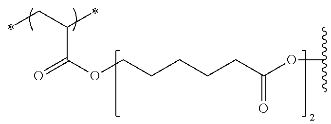 |
 |
| P-9 |
 |
 |
| P-10 |
 |
 |
| P-11 |
 |
 |
| P-12 |
 |
 |
| Structure of Compound A | |
| A-1-2 | |
| P-6 |
 |
|
| P-7 |
 |
|
| P-8 |
 |
|
| P-9 |
 |
|
| P-10 |
 |
|
| P-11 |
 |
|
| P-12 |
 |
|
| Structure of Compound A | |
| A-1-3 | |
| P-6 |
 |
|
| P-7 |
 |
|
| P-8 |
 |
|
| P-9 |
 |
|
| P-10 |
 |
|
| P-11 |
 |
|
| P-12 |
 |
|
| Properties of Compound A | Molar Ratio [mol %] of |
| Acid Value | C≡C Value | Compound A |
| Mw | [mgKOH/g] | [mmol/g] | A-1-1 | A-1-2 | A-1-3 | ||
| P-6 | 22000 | 78 | 0.7 | 32% | 5% | 63% | |
| P-7 | 18000 | 78 | 0.7 | 32% | 4% | 64% | |
| P-8 | 20000 | 78 | 0.47 | 25% | 9% | 67% | |
| P-9 | 19000 | 78 | 0.7 | 32% | 10% | 58% | |
| P-10 | 21000 | 78 | 0.7 | 34% | 5% | 61% | |
| P-11 | 18000 | 78 | 0.7 | 32% | 11% | 57% | |
| P-12 | 17000 | 78 | 0.7 | 32% | 10% | 58% | |
| TABLE 2 | |
| Structure of Compound A | |
| A-1-1 |
| C═C Group Structure | A-1-2 | ||
| P-13 |
 |
|
 |
| P-14 |
 |
|
 |
| P-15 |
 |
 |
 |
| P-16 |
 |
|
 |
| P-17 |
 |
|
 |
| P-18 |
 |
 |
 |
| P-19 |
 |
|
 |
| P-20 |
 |
|
 |
| Properties of Compound A |
| Structure of Compound A | Acid Value | C═C Value | Molar Ratio [mol %] of Compound A |
| A-1-3 | Mw | [mgKOH/g] | [mmol/g] | A-1-1 | A-1-2 | A-1-3 | ||
 |
23000 | 78 | 0.7 | 32% | 5% | 64% | ||
| None | 18000 | Zero | 0.7 | 58% | 42% | 0% | ||
 |
21000 | 78 | 0.7 | 31% | 7% | 62% | ||
 |
22000 | 78 | 0.7 | 31% | 7% | 62% | ||
 |
19000 | 78 | 0.7 | 29% | 13% | 58% | ||
 |
20000 | 78 | 0.7 | 31% | 7% | 62% | ||
 |
21000 | 78 | 0.7 | 31% | 7% | 62% | ||
 |
20000 | 78 | 0.7 | 29% | 13% | 58% | ||
| TABLE 3 | |
| Structure of Compound A | |
| A-1-1 |
| C═C Group Structure | A-1-2 | ||
| P-21 |
 |
 |
 |
| P-22 |
 |
 |
 |
| P-23 |
 |
 |
 |
| P-24 |
 |
 |
 |
| P-25 |
 |
 |
 |
| P-26 |
 |
 |
 |
| P-27 |
 |
 |
 |
| Properties of Compound A | Molar Ratio [mol %] of |
| Structure of Compound A | Acid Value | C═C Value | Compound A |
| A-1-3 | Mw | [mgKOH/g] | [mmol/g] | A-1-1 | A-1-2 | A-1-3 | |
| P-21 |
 |
22000 | 78 | 0.7 | 30% | 10% | 60% |
| P-22 |
 |
20000 | 78 | 0.7 | 30% | 10% | 60% |
| P-23 |
 |
21000 | 78 | 0.7 | 28% | 17% | 55% |
| P-24 |
 |
18000 | 78 | 0.7 | 31% | 13% | 56% |
| P-25 |
 |
21000 | 78 | 0.7 | 31% | 13% | 56% |
| P-26 |
 |
22000 | 78 | 0.7 | 28% | 22% | 50% |
| P-27 |
 |
20000 | 78 | 0.7 | 32% | 6% | 62% |
| TABLE 4 | |
| Structure of Compound A | |
| A-1-1 |
| C═C Group | |||
| Structure | A-1-2 | ||
| P-28 |
 |
|
 |
| P-29 |
 |
|
 |
| P-30 |
 |
 |
 |
| P-31 |
 |
|
 |
| Properties of Compound A | Molar Ratio [mol %] of |
| Structure of Compound A | Acid Value | C═C Value | Compound A |
| A-1-3 | Mw | [mgKOH/g] | [mmol/g] | A-1-1 | A-1-2 | A-1-3 | |
| P-28 |
 |
21000 | 78 | 0.7 | 32% | 5% | 63% |
| P-29 |
 |
20000 | 78 | 0.7 | 30% | 10% | 60% |
| P-30 |
 |
23000 | 78 | 0.7 | 32% | 6% | 62% |
| P-31 |
 |
22000 | 78 | 0.7 | 32% | 6% | 62% |
| TABLE 5 | |
| Structure of Compound A | |
| A-1-1 |
| C═C Group | |||
| Structure | A-1-2 | ||
| P-32 |
 |
|
 |
| P-33 |
 |
 |
 |
| P-34 |
 |
|
 |
| P-35 |
 |
|
 |
| Properties of Compound A | Molar Ratio [mol %] of |
| Structure of Compound A | Acid Value | C═C Value | Compound A |
| A-1-3 | Mw | [mgK OH/g] | [mmol/g] | A-1-1 | A-1-2 | A-1-3 | |
| P-32 |
 |
19000 | 78 | 0.7 | 31% | 9% | 60% |
| P-33 |
 |
21000 | 78 | 0.7 | 31% | 6% | 62% |
| P-34 |
 |
22000 | 78 | 0.7 | 32% | 6% | 63% |
| P-35 |
 |
20000 | 78 | 0.7 | 30% | 10% | 60% |
| TABLE 6 | |
| Structure of Compound A | |
| A-1-1 |
| C═C Group Structure | A-1-2 | A-1-3 | ||
| P-36 |
 |
|
 |
 |
| P-37 |
 |
|
 |
 |
| P-38 |
 |
|
 |
 |
| P-39 |
 |
|
 |
 |
| P-40 |
 |
|
 |
 |
| P-41 |
 |
|
 |
 |
| Properties of Compound A | Molar Ratio [mol %] of |
| Acid Value | C═C Value | Compound A |
| MW | [mgKOH/g] | [mmol/g] | A-1-1 | A-1-2 | A-1-3 | ||
| P-36 | 21000 | 78 | 0.7 | 32% | 6% | 62% | |
| P-37 | 20000 | 78 | 0.7 | 32% | 5% | 63% | |
| P-38 | 19000 | 78 | 0.7 | 30% | 10% | 60% | |
| P-39 | 20000 | 78 | 0.7 | 32% | 6% | 63% | |
| P-40 | 21000 | 78 | 0.7 | 32% | 5% | 63% | |
| P-41 | 18000 | 78 | 0.7 | 30% | 9% | 60% | |


| TABLE 7 | |
| Structure of Compound A | |
| A-1-1 | |
| C═C Group Structure | ||
| P-46 |
 |
 |
| P-47 |
 |
 |
| P-48 |
 |
 |
| P-49 |
 |
 |
| P-50 |
 |
 |
| P-51 |
 |
|
| P-52 |
 |
|
| P-53 |
 |
|
| Structure of Compound A | |
| A-1-2 | |
| P-46 |
 |
| P-47 |
 |
| P-48 |
 |
| P-49 |
 |
| P-50 |
 |
| P-51 |
 |
| P-52 |
 |
| P-53 |
 |
| Properties of Compound A | Molar Ratio [mol %] of |
| Structure of Compound A | Acid Value | C═C Value | Compound A |
| A-1-3 | Mw | [mgKOH/g] | [mmol/g] | A-1-1 | A-1-2 | A-1-3 | |
| P-46 |
 |
21000 | 78 | 0.7 | 32% | 5% | 63% |
| P-47 |
 |
18000 | 78 | 0.7 | 32% | 5% | 63% |
| P-48 |
 |
22000 | 24 | 0.7 | 52% | 16% | 32% |
| P-49 |
 |
21000 | 104 | 0.47 | 25% | 9% | 66% |
| P-50 |
 |
20000 | 156 | 0.7 | 19% | 6% | 75% |
| P-51 |
 |
22000 | 78 | 1.4 | 48% | 5% | 47% |
| P-52 |
 |
18000 | 78 | 2.1 | 58% | 2% | 39% |
| P-53 |
 |
18000 | 78 | 3.0 | 67% | 3% | 31% |
In the composition according to the embodiment of the present invention, the content of the compound A is preferably 5 to 50 mass % with respect to the total solid content of the composition. The lower limit is 7 mass % or higher and more preferably 10 mass % or higher. The upper limit is 40 mass % or lower and more preferably 30 mass % or lower.
<<Polymerizable Compounds>>
The composition according to the embodiment of the present invention may include a polymerizable compound other than the compound A. As the polymerizable compound, a compound that is polymerizable by the action of a radical is preferable. That is, it is preferable that the polymerizable compound is a radically polymerizable compound. As the polymerizable compound, a compound having one or more ethylenically unsaturated groups is preferable, a compound having two or more ethylenically unsaturated groups is more preferable, and a compound having three or more ethylenically unsaturated groups is still more preferable. The upper limit of the number of the ethylenically unsaturated groups is, for example, preferably 15 or less and more preferably 6 or less. Examples of the ethylenically unsaturated group include a vinyl group, a styrene group, an allyl group, a methallyl group, and a (meth)acryloyl group. Among these, a (meth)acryloyl group is preferable. The polymerizable compound is preferably a (meth)acrylate compound having 3 to 15 functional groups and more preferably a (meth)acrylate compound having 3 to 6 functional groups.
The polymerizable compound may be in the form of a monomer or a polymer and is preferably a monomer. The molecular weight of the monomer type polymerizable compound is preferably 100 or higher and lower than 3000. The upper limit is preferably 2000 or lower and more preferably 1500 or lower. The lower limit is preferably 150 or higher and more preferably 250 or higher. In addition, it is preferable that the polymerizable compound is a compound substantially not having a molecular weight distribution. Here, the compound substantially not having a molecular weight distribution represents that the dispersity (weight-average molecular weight (Mw)/number-average molecular weight (Mn)) of the compound is preferably 1.0 to 1.5 and more preferably 1.0 to 1.3.
Examples of the polymerizable compound can be found in paragraphs “0033” and “0034” of JP2013-253224A, the content of which is incorporated herein by reference. As the polymerizable compound, ethyleneoxy-modified pentaerythritol tetraacrylate (as a commercially available product, NK ESTER ATM-35E manufactured by Shin-Nakamura Chemical Co., Ltd.), dipentaerythritol triacrylate (as a commercially available product, KAYARAD D-330 manufactured by Nippon Kayaku Co., Ltd.), dipentaerythritol tetraacrylate (as a commercially available product, KAYARAD D-320 manufactured by Nippon Kayaku Co., Ltd.), dipentaerythritol penta(meth)acrylate (as a commercially available product, KAYARAD D-310 manufactured by Nippon Kayaku Co., Ltd.), dipentaerythritol hexa(meth)acrylate (as a commercially available product, KAYARAD DPHA manufactured by Nippon Kayaku Co., Ltd., A-DPH-12E, manufactured by Shin-Nakamura Chemical Co., Ltd.), or a compound having a structure in which the (meth)acryloyl group is bonded through an ethylene glycol residue and/or a propylene glycol residue is preferable. In addition, oligomers of the above-described examples can be used. For example, the details of the polymerizable compound can be found in paragraphs “0034” to “0038” of JP2013-253224A, the content of which is incorporated herein by reference. Examples of the compound having an ethylenically unsaturated bond include a polymerizable monomer in paragraph “0477” of JP2012-208494A (corresponding to paragraph “0585” of US2012/0235099A), the content of which is incorporated herein by reference. In addition, diglycerin ethylene oxide (EO)-modified (meth)acrylate (as a commercially available product, M-460 manufactured by Toagosei Co., Ltd.), pentaerythritol tetraacrylate (A-TMMT manufactured by Shin-Nakamura Chemical Co., Ltd.), or 1,6-hexanediol diacrylate (KAYARAD HDDA manufactured by Nippon Kayaku Co., Ltd.) is also preferable. Oligomers of the above-described examples can be used. For examples, RP-1040 (manufactured by Nippon Kayaku Co., Ltd.) is used.
The polymerizable compound may have an acid group such as a carboxyl group, a sulfo group, or a phosphate group. Examples of a commercially available product of the polymerizable compound having an acid group include ARONIX M-305, M-510, and M-520 (manufactured by Toagosei Co., Ltd.). The acid value of the polymerizable compound having an acid group is preferably 0.1 to 40 mgKOH/g. The lower limit is preferably 5 mgKOH/g or higher. The upper limit is preferably 30 mgKOH/g or lower.
In addition, it is also preferable that the polymerizable compound is a compound having a caprolactone structure. The polymerizable compound having a caprolactone structure is not particularly limited as long as it has a caprolactone structure in the molecule thereof, and examples thereof include s-caprolactone-modified polyfunctional (meth)acrylate obtained by esterification of a polyhydric alcohol, (meth)acrylic acid, and ϵ-caprolactone, the polyhydric alcohol being, for example, trimethylolethane, ditrimethylolethane, trimethylolpropane, ditrimethylolpropane, pentaerythritol, dipentaerythritol, tripentaerythritol, glycerin, diglycerol, or trimethylolmelamine. Examples of the polymerizable compound having a caprolactone structure can be found in paragraphs “0042” to “0045” of JP2013-253224A, the content of which is incorporated herein by reference. Examples of the compound having a caprolactone structure include: DPCA-20, DPCA-30, DPCA-60, and DPCA-120 which are commercially available as KAYARADDPCA series manufactured by Nippon Kayaku Co., Ltd.; SR-494 (manufactured by Sartomer) which is a tetrafunctional acrylate having four ethyleneoxy chains; and TPA-330 which is a trifunctional acrylate having three isobutyleneoxy chains.
As the polymerizable compound, a urethane acrylate described in JP1973-041708B (JP-S48-041708B), JP1976-037193A (JP-S51-037193A), JP1990-032293B (JP-H2-032293B), or JP1990-016765B (JP-H2-016765B), or a urethane compound having an ethylene oxide skeleton described in JP1983-049860B (JP-S58-049860B), JP1981-017654B (JP-S56-017654B), JP1987-039417B (JP-S62-039417B), or JP1987-039418B (JP-S62-039418B) is also preferable. In addition, an addition-polymerizable compound having an amino structure or a sulfide structure in the molecules described in JP1988-277653A (JP-S63-277653A), JP1988-260909A (JP-S63-260909A), or JP1989-105238A (JP-H1-105238A) can be used. Examples of a commercially available product of the polymerizable compound include URETHANE OLIGOMER UAS-10 and UAB-140 (manufactured by Sanyo-Kokusaku Pulp Co., Ltd.), UA-7200 (manufactured by Shin-Nakamura Chemical Co., Ltd.), DPHA-40H (manufactured by Nippon Kayaku Co., Ltd.), and UA-30611, UA-306T, UA-306I, AH-600, T-600 and AI-600 (manufactured by Kyoeisha Chemical Co., Ltd.).
In a case where the composition according to the embodiment of the present invention includes the polymerizable compound other than the compound A, the content of the polymerizable compound other than the compound A is preferably 0.1 to 40 mass % with respect to the total solid content of the composition. For example, the lower limit is more preferably 0.5 mass % or higher and still more preferably 1 mass % or higher. For example, the upper limit is more preferably 30 mass % or lower and still more preferably 20 mass % or lower. The composition according to the embodiment of the present invention may not substantially include the polymerizable compound other than the compound A. The composition according to the embodiment of the present invention not substantially including the polymerizable compound other than the compound A represents that the content of the polymerizable compound other than the compound A is preferably 0.05 mass % or lower, more preferably 0.01 mass % or lower, and still more preferably 0 mass % with respect to the total solid content of the composition.
In addition, the total content of the compound A and the polymerizable compound other than the compound A is preferably 5 to 50 mass % with respect to the total solid content of the composition. For example, the lower limit is more preferably 7 mass % or higher and still more preferably 10 mass % or higher. For example, the upper limit is more preferably 45 mass % or lower and still more preferably 40 mass % or lower.
As the polymerizable compound, one kind may be used alone, or two or more kinds may be used in combination. In a case where two or more polymerizable compounds are used in combination, it is preferable that the total content of the two or more polymerizable compounds is in the above-described range.
<<Photopolymerization Initiator>>
The composition according to the embodiment of the present invention may include a photopolymerization initiator. The photopolymerization initiator is not particularly limited and can be appropriately selected from well-known photopolymerization initiators. For example, a compound having photosensitivity to light in a range from an ultraviolet range to a visible range is preferable. It is preferable that the photopolymerization initiator is a photoradical polymerization initiator.
Examples of the photopolymerization initiator include a halogenated hydrocarbon derivative (for example, a compound having a triazine skeleton or a compound having an oxadiazole skeleton), an acylphosphine compound, a hexaarylbiimidazole, an oxime compound, an organic peroxide, a thio compound, a ketone compound, an aromatic onium salt, an α-hydroxyketone compound, and an α-aminoketone compound. In addition, from the viewpoint of exposure sensitivity, as the photopolymerization initiator, a trihalomethyltriazine compound, a benzyldimethylketal compound, an α-hydroxyketone compound, an α-aminoketone compound, an acylphosphine compound, a phosphine oxide compound, a metallocene compound, an oxime compound, a triarylimidazole dimer, an onium compound, a benzothiazole compound, a benzophenone compound, an acetophenone compound, a cyclopentadiene-benzene-iron complex, a halomethyl oxadiazole compound, or a 3-aryl-substituted coumarin compound is preferable, a compound selected from the group consisting of an oxime compound, an α-hydroxy ketone compound, an α-aminoketone compound, and an acylphosphine compound is more preferable, and an oxime compound is still more preferable. The details of the photopolymerization initiator can be found in paragraphs “0065” to “0111” of JP2014-130173A, the content of which is incorporated herein by reference.
Examples of a commercially available product of the α-hydroxyketone compound include IRGACURE-184, DAROCUR-1173, IRGACURE-500, IRGACURE-2959, and IRGACURE-127 (all of which are manufactured by BASF SE). Examples of a commercially available product of the α-aminoketone compound include IRGACURE-907, IRGACURE-369, IRGACURE-379, and IRGACURE-379EG (all of which are manufactured by BASF SE). Examples of a commercially available product of the acylphosphine compound include IRGACURE-819, and DAROCUR-TPO (all of which are manufactured by BASF SE).
As the oxime compound, a compound described in JP2001-233842A, a compound described in JP2000-080068A, a compound described in JP2006-342166A, or a compound described in JP2016-021012A can be used. Examples of the oxime compound which can be preferably used in the present invention include 3-benzoyloxyiminobutane-2-one, 3-acetoxyiminobutane-2-one, 3-propionyloxyiminobutane-2-one, 2-acetoxyiminopentane-3-one, 2-acetoxyimino-1-phenylpropane-1-one, 2-benzoyloxyimino-1-phenylpropane-1-one, 3-(4-toluene sulfonyloxy)iminobutane-2-one, and 2-ethoxycarbonyloxyimino-1-phenylpropane-1-one. In addition, examples of the oxime compound include a compound described in J. C. S. Perkin II (1979), pp. 1653-1660, J. C. S. Perkin II (1979), pp. 156-162 and Journal of Photopolymer Science and Technology (1995), pp. 202-232, JP2000-066385A, JP2000-080068A, JP2004-534797A, or JP2006-342166A. As a commercially available product of the oxime compound, IRGACURE-OXE01, IRGACURE-OXE02, IRGACURE-OXE03, or IRGACURE-OXE04 (all of which are manufactured by BASF SE) can also be preferably used. In addition, TR-PBG-304 (manufactured by Changzhou Tronly New Electronic Materials Co., Ltd.), ADEKA ARKLS NCI-831 (manufactured by Adeka Corporation), ADEKA ARKLS NCI-930 (manufactured by Adeka Corporation), ADEKA OPTOMER N-1919 (manufactured by Adeka Corporation, a photopolymerization initiator 2 described in JP2012-014052A) can also be used.
In the present invention, an oxime compound having a fluorene ring can also be used as the photopolymerization initiator. Specific examples of the oxime compound having a fluorene ring include a compound described in JP2014-137466A. The content is incorporated herein by reference.
In the present invention, an oxime compound having a fluorine atom can also be used as the photopolymerization initiator. Specific examples of the oxime compound having a fluorine atom include a compound described in JP2010-262028A, Compound 24 and 36 to 40 described in JP2014-500852A, and Compound (C-3) described in JP2013-164471A. The content is incorporated herein by reference.
In the present invention, as the photopolymerization initiator, an oxime compound having a nitro group can be used. It is preferable that the oxime compound having a nitro group is a dimer. Specific examples of the oxime compound having a nitro group include a compound described in paragraphs “0031” to “0047” of JP2013-114249A and paragraphs “0008” to “0012” and “0070” to “0079” of JP2014-137466A, a compound described in paragraphs “0007” to 0025″ of JP4223071B, and ADEKA ARKLS NCI-831 (manufactured by Adeka Corporation).
Hereinafter, specific examples of the oxime compound which are preferably used in the present invention are shown below, but the present invention is not limited thereto.


The oxime compound is preferably a compound having an absorption maximum in a wavelength range of 350 nm to 500 nm and more preferably a compound having an absorption maximum in a wavelength range of 360 nm to 480 nm. In addition, the oxime compound is preferably a compound having a high absorbance at 365 nm and 405 nm.
The molar absorption coefficient of the oxime compound at 365 nm or 405 nm is preferably 1000 to 300000, more preferably 2000 to 300000, and still more preferably 5000 to 200000 from the viewpoint of sensitivity.
The molar absorption coefficient of the compound can be measured using a well-known method. For example, it is preferable that the molar absorption coefficient can be measured using a spectrophotometer (Cary-5 spectrophotometer, manufactured by Varian Medical Systems, Inc.) and ethyl acetate as a solvent at a concentration of 0.01 g/L.
It is preferable that the photopolymerization initiator includes an oxime compound and an α-aminoketone compound. By using the oxime compound and the α-aminoketone compound in combination, the developability is improved, and a pattern having excellent rectangularity is likely to be formed. In a case where the oxime compound and the α-aminoketone compound are used in combination, the content of the α-aminoketone compound is preferably 50 to 600 parts by mass and more preferably 150 to 400 parts by mass with respect to 100 parts by mass of the oxime compound.
The content of the photopolymerization initiator is preferably 0.1 to 50 mass %, more preferably 0.5 to 30 mass %, and still more preferably 1 to 20 mass % with respect to the total solid content of the composition. In a case where the content of the photopolymerization initiator is in the above-described range, developability is excellent. The composition according to the embodiment of the present invention may include one photopolymerization initiator or two or more photopolymerization initiators. In a case where the composition includes two or more photopolymerization initiators, it is preferable that the total content of the photopolymerization initiators is in the above-described range.
<<Resin>>
The composition according to the embodiment of the present invention may further include a resin other than the compound A. Examples of the resin other than the compound A include a resin not having a graft chain and a resin not having a radically polymerizable unsaturated bond group. In the present invention, the resin is mixed, for example, in order to disperse particles of the pigments and the like in the composition or to be added as a binder. The resin which is mainly used to disperse particles of the pigments and the like will also be called a dispersant. However, the above-described uses of the resin are merely exemplary, and the resin can be used for purposes other than the uses.
The weight-average molecular weight (Mw) of the resin is preferably 2000 to 2000000. The upper limit is preferably 1000000 or lower and more preferably 500000 or lower. The lower limit is preferably 3000 or higher and more preferably 5000 or higher.
Examples of the resin include a (meth)acrylic resin, an epoxy resin, an enethiol resin, a polycarbonate resin, a polyether resin, a polyarylate resin, a polysulfone resin, a polyethersulfone resin, a polyphenylene resin, a polyarylene ether phosphine oxide resin, a polyimide resin, a polyamide imide resin, a polyolefin resin, a cyclic olefin resin, a polyester resin, and a styrene resin. Among these resins, one kind may be used alone, or a mixture of two or more kinds may be used. As the cyclic olefin resin, a norbornene resin can be preferably used from the viewpoint of improving heat resistance. Examples of a commercially available product of the norbornene resin include ARTON series (for example, ARTON F4520, manufactured by JSR Corporation). Examples of the epoxy resin include an epoxy resin which is a glycidyl-etherified product of a phenol compound, an epoxy resin which is a glycidyl-etherified product of various novolac resins, an alicyclic epoxy resin, an aliphatic epoxy resin, a heterocyclic epoxy resin, a glycidyl ester epoxy resin, a glycidyl amine epoxy resin, an epoxy resin which is a glycidylated product of a halogenated phenol, a condensate of a silicon compound having an epoxy group and another silicon compound, and a copolymer of a polymerizable unsaturated compound having an epoxy group and another polymerizable unsaturated compound. In addition, for example, MARPROOF G-0150M, G-0105SA, G-0130SP, G-0250SP, G-1005S, G-1005SA, G-1010S, G-2050M, G-01100, or G-01758 (manufactured by NOF Corporation, an epoxy group-containing polymer) can also be used. In addition, as the resin, a resin described in Examples of WO2016/088645A can also be used.
The resin used in the present invention may have an acid group. Examples of the acid group include a carboxyl group, a phosphate group, a sulfo group, and a phenolic hydroxyl group. Among these, a carboxyl group is preferable. Among these acid groups, one kind may be used alone, or two or more kinds may be used in combination. The resin having an acid group can also be used as an alkali-soluble resin.
As the resin having an acid group, a polymer having a carboxyl group at a side chain is preferable. Specific examples of the resin include an alkali-soluble phenol resin such as a methacrylic acid copolymer, an acrylic acid copolymer, an itaconic acid copolymer, a crotonic acid copolymer, a maleic acid copolymer, a partially esterified maleic acid copolymer, or a novolac resin, an acidic cellulose derivative having a carboxyl group at a side chain thereof, and a resin obtained by adding an acid anhydride to a polymer having a hydroxyl group. In particular, a copolymer of (meth)acrylic acid and another monomer which is copolymerizable with the (meth)acrylic acid is preferable as the alkali-soluble resin. Examples of the monomer which is copolymerizable with the (meth)acrylic acid include an alkyl (meth)acrylate, an aryl (meth)acrylate, and a vinyl compound. Examples of the alkyl (meth)acrylate and the aryl (meth)acrylate include methyl (meth)acrylate, ethyl (meth)acrylate, propyl (meth)acrylate, butyl (meth)acrylate, isobutyl (meth)acrylate, pentyl (meth)acrylate, hexyl (meth)acrylate, octyl (meth)acrylate, phenyl (meth)acrylate, benzyl (meth)acrylate, tolyl (meth)acrylate, naphthyl (meth)acrylate, and cyclohexyl (meth)acrylate. Examples of the vinyl compound include styrene, α-methylstyrene, vinyl toluene, glycidyl methacrylate, acrylonitrile, vinyl acetate, N-vinylpyrrolidone, tetrahydrofurfuryl methacrylate, a polystyrene macromonomer, and a polymethyl methacrylate macromonomer. Examples of other monomers include a N-position-substituted maleimide monomer described in JP 1998-300922A (JP-H10-300922A) such as N-phenylmaleimide or N-cyclohexylmaleimide. Among these monomers which are copolymerizable with the (meth)acrylic acid, one kind may be used alone, or two or more kinds may be used in combination.
The resin having an acid group may further have a polymerizable group. Examples of the polymerizable group include an allyl group, a methallyl group, and a (meth)acryloyl group. Examples of a commercially available product of the resin include DIANAL NR series (manufactured by Mitsubishi Rayon Co., Ltd.), PHOTOMER 6173 (a carboxyl group-containing polyurethane acrylate oligomer; manufactured by Diamond Shamrock Co., Ltd.), VISCOAT R-264 and KS Resist 106 (both of which are manufactured by Osaka Organic Chemical Industry Ltd.), CYCLOMER-P series (for example, ACA230AA) and PLAKCEL CF200 series (both of which manufactured by Daicel Corporation), EBECRYL 3800 (manufactured by Daicel-UCB Co., Ltd.), and ACRYCURE RD-F8 (manufactured by Nippon Shokubai Co., Ltd.).
As the resin having an acid group, a copolymer including benzyl (meth)acrylate and (meth)acrylic acid; a copolymer including benzyl (meth)acrylate, (meth)acrylic acid, and 2-hydroxyethyl (meth)acrylate; or a multi-component copolymer including benzyl (meth)acrylate, (meth)acrylic acid, and another monomer can be preferably used. In addition, copolymers described in JP1995-140654A (JP-H7-140654A) obtained by copolymerization of 2-hydroxyethyl (meth)acrylate can be preferably used, and examples thereof include: a copolymer including 2-hydroxypropyl (meth)acrylate, a polystyrene macromonomer, benzyl methacrylate, and methacrylic acid; a copolymer including 2-hydroxy-3-phenoxypropyl acrylate, a polymethyl methacrylate macromonomer, benzyl methacrylate, and methacrylic acid; a copolymer including 2-hydroxyethyl methacrylate, a polystyrene macromonomer, methyl methacrylate, and methacrylic acid; or a copolymer including 2-hydroxyethyl methacrylate, a polystyrene macromonomer, benzyl methacrylate, and methacrylic acid.
As the resin having an acid group, a polymer that includes a repeating unit derived from monomer components including a compound represented by the following Formula (ED1) and/or a compound represented by the following Formula (ED2) (hereinafter, these compounds will also be referred to as “ether dimer”) is also preferable.

In Formula (ED1), R1 and R2 each independently represent a hydrogen atom or a hydrocarbon group having 1 to 25 carbon atoms which may have a substituent.

In Formula (ED2), R represents a hydrogen atom or an organic group having 1 to 30 carbon atoms. Specific examples of Formula (ED2) can be found in the description of JP2010-168539A.
Specific examples of the ether dimer can be found in paragraph “0317” of JP2013-029760A, the content of which is incorporated herein by reference. Among these ether dimers, one kind may be used alone, or two or more kinds may be used in combination.
The resin having an acid group may include a repeating unit which is derived from a compound represented by the following Formula (X).

In Formula (X), R1 represents a hydrogen atom or a methyl group, R2 represents an alkylene group having 2 to 10 carbon atoms, and R3 represents a hydrogen atom or an alkyl group having 1 to 20 carbon atoms which may have a benzene ring. n represents an integer of 1 to 15.
The details of the resin having an acid group can be found in paragraphs “0558” to “0571” of JP2012-208494A (corresponding to paragraphs “0685” to “0700” of US2012/0235099A) and paragraphs “0076” to “0099” of JP2012-198408A, the contents of which are incorporated herein by reference. In addition, as the resin having an acid group, a commercially available product may also be used. Examples of the commercially available product include ACRYBASE FF-426 (manufactured by Fujikura Kasei Co., Ltd.).
The acid value of the resin having an acid group is preferably 30 to 200 mgKOH/g. The lower limit is preferably 50 mgKOH/g or higher and more preferably 70 mgKOH/g or higher. The upper limit is preferably 150 mgKOH/g or lower and more preferably 120 mgKOH/g or lower.
Examples of the resin having an acid group include resins having the following structures. In the following structural formulae, Me represents a methyl group.

The composition according to the embodiment of the present invention may include a resin as a dispersant. Examples of the dispersant include an acidic dispersant (acidic resin) and a basic dispersant (basic resin). Here, the acidic dispersant (acidic resin) refers to a resin in which the amount of an acid group is more than the amount of a basic group. In a case where the sum of the amount of an acid group and the amount of a basic group in the acidic dispersant (acidic resin) is represented by 100 mol %, the amount of the acid group in the acidic resin is preferably 70 mol % or higher and more preferably substantially 100 mol %. The acid group in the acidic dispersant (acidic resin) is preferably a carboxyl group. An acid value of the acidic dispersant (acidic resin) is preferably 40 to 105 mgKOH/g, more preferably 50 to 105 mgKOH/g, and still more preferably 60 to 105 mgKOH/g. In addition, the basic dispersant (basic resin) refers to a resin in which the amount of a basic group is more than the amount of an acid group. In a case where the sum of the amount of an acid group and the amount of a basic group in the basic dispersant (basic resin) is represented by 100 mol %, the amount of the basic group in the basic resin is preferably higher than 50 mol %. The basic group in the basic dispersant is preferably an amino group.
It is preferable that the resin A used as the dispersant further includes a repeating unit having an acid group. By the resin, which is used as the dispersant, including the repeating unit having an acid group, in a case where a pattern is formed using a photolithography method, the amount of residues formed in an underlayer of a pixel can be reduced.
It is preferable that the resin used as the dispersant is a graft copolymer. Since the graft copolymer has affinity to the solvent due to the graft chain, the pigment dispersibility and the dispersion stability over time are excellent. The details of the graft copolymer can be found in the description of paragraphs “0025” to “0094” of JP2012-255128A, the content of which is incorporated herein by reference. In addition, specific examples of the graft copolymer include the following resins. The following resin may also be a resin having an acid group (alkali-soluble resin). In addition, other examples of the graft copolymer include resins described in paragraphs “0072” to “0094” of JP2012-255128A, the content of which is incorporated herein by reference.

In addition, in the present invention, as the resin (dispersant), an oligoimine dispersant having a nitrogen atom at at least either a main chain or a side chain is also preferably used. As the oligoimine dispersant, a resin, which includes a structural unit having a partial structure X with a functional group (pKa: 14 or lower) and a side chain Y having 40 to 10000 atoms and has a basic nitrogen atom at at least either a main chain or a side chain, is preferable. The basic nitrogen atom is not particularly limited as long as it is a nitrogen atom exhibiting basicity. The oligoimine dispersant can be found in the description of paragraphs “0102” to “0166” of JP2012-255128A, the content of which is incorporated herein by reference. As the oligoimine dispersant, a resin described in paragraphs “0168” to “0174” of JP2012-255128A can be used.
The dispersant is available as a commercially available product, and specific examples thereof include Disperbyk-111 (manufactured by BYK Chemie) and SOLSPERSE 76500 (manufactured by Lubrication Technology Inc.). In addition, a pigment dispersant described in paragraphs “0041” to “0130” of JP2014-130338A can also be used, the content of which is incorporated herein by reference. In addition, the resin having an acid group or the like can also be used as a dispersant.
In a case where the composition according to the embodiment of the present invention includes a resin, the content of the resin is preferably higher than 0 mass % and 30 mass % or lower with respect to the total solid content of the composition according to the embodiment of the present invention.
<<Coloring Material that allows Transmission of Infrared Light and Shields Visible Light>>
The composition according to the embodiment of the present invention may also include the coloring material that allows transmission of infrared light and shields visible light (hereinafter, also referred to as “coloring material that shields visible light”). In the present invention, it is preferable that the coloring material that shields visible light is a coloring material that absorbs light in a wavelength range of violet to red. In addition, in the present invention, it is preferable that the coloring material that shields visible light is a coloring material that shields light in a wavelength range of 400 to 640 nm. In addition, it is preferable that the coloring material that shields visible light is a coloring material that allows transmission of light in a wavelength range of 900 to 1300 nm. In the present invention, it is preferable that the coloring material that shields visible light satisfies at least one of the following requirement (A) or (B).
(1): The coloring material that shields visible light includes two or more chromatic colorants, and a combination of the two or more chromatic colorants forms black.
(2) The coloring material that shields light in the visible range includes an organic black colorant. In the aspect (2), it is preferable that the coloring material that shields light in the visible range further includes a chromatic colorant.
In the present invention, the chromatic colorant denotes a colorant other than a white colorant and a black colorant. In addition, in the present invention, the organic black colorant as the coloring material that shields visible light denotes a material that absorbs visible light and allows transmission of at least a part of infrared light. Accordingly, in the present invention, the organic black colorant as the coloring material that shields visible light does not denote a black colorant that absorbs both visible light and infrared light, for example, carbon black or titanium black. It is preferable that the organic black colorant is a colorant having an absorption maximum in a wavelength range of 400 nm to 700 nm.
In the present invention, it is preferable that the coloring material that shields visible light is a material in which a ratio A/B of a minimum value A of an absorbance in a wavelength range of 400 to 640 nm to a minimum value B of an absorbance in a wavelength range of 900 to 1300 nm is 4.5 or higher.
The above-described characteristics may be satisfied using one material alone or using a combination of a plurality of materials. For example, in the aspect (1), it is preferable that the spectral characteristics are satisfied using a combination of a plurality of chromatic colorants. In addition, in the aspect (2), the spectral characteristics may be satisfied using an organic black colorant. In addition, the spectral characteristics may be satisfied using a combination of an organic black colorant and a chromatic colorant.
(Chromatic Colorant)
In the present invention, the chromatic colorant is selected from the group consisting of a red colorant, a green colorant, a blue colorant, a yellow colorant, a violet colorant, and an orange colorant. In the present invention, the chromatic colorant may be a pigment or a dye. It is preferable that the chromatic colorant is a pigment. It is preferable that an average particle size (r) of the pigment satisfies preferably 20 nm≤r≤300 nm, more preferably 25 nm≤r≤250 nm, and still more preferably 30 nm≤r≤200 nm. “Average particle size” described herein denotes the average particle size of secondary particles which are aggregates of primary particles of the pigment. In addition, regarding a particle size distribution of the secondary particles of the pigment (hereinafter, simply referred to as “particle size distribution”) which can be used, secondary particles having a particle size of (average particle size±100) nm account for preferably 70 mass % or higher and more preferably 80 mass % or higher in the pigment. The particle size distribution of the secondary particles can be measured using a scattering intensity distribution.
As the pigment, an organic pigment is preferable. Preferable examples of the organic pigment are as follows:
Color Index (C.I.) Pigment Yellow 1, 2, 3, 4, 5, 6, 10, 11, 12, 13, 14, 15, 16, 17, 18, 20, 24, 31, 32, 34, 35, 35:1, 36, 36:1, 37, 37:1, 40, 42, 43, 53, 55, 60, 61, 62, 63, 65, 73, 74, 77, 81, 83, 86, 93, 94, 95, 97, 98, 100, 101, 104, 106, 108, 109, 110, 113, 114, 115, 116, 117, 118, 119, 120, 123, 125, 126, 127, 128, 129, 137, 138, 139, 147, 148, 150, 151, 152, 153, 154, 155, 156, 161, 162, 164, 166, 167, 168, 169, 170, 171, 172, 173, 174, 175, 176, 177, 179, 180, 181, 182, 185, 187, 188, 193, 194, 199, 213, and 214 (all of which are yellow pigments);
C.I. Pigment Orange 2, 5, 13, 16, 17:1, 31, 34, 36, 38, 43, 46, 48, 49, 51, 52, 55, 59, 60, 61, 62, 64, 71, and 73 (all of which are orange pigments);
C.I. Pigment Red 1, 2, 3, 4, 5, 6, 7, 9, 10, 14, 17, 22, 23, 31, 38, 41, 48:1, 48:2, 48:3, 48:4, 49, 49:1, 49:2, 52:1, 52:2, 53:1, 57:1, 60:1, 63:1, 66, 67, 81:1, 81:2, 81:3, 83, 88, 90, 105, 112, 119, 122, 123, 144, 146, 149, 150, 155, 166, 168, 169, 170, 171, 172, 175, 176, 177, 178, 179, 184, 185, 187, 188, 190, 200, 202, 206, 207, 208, 209, 210, 216, 220, 224, 226, 242, 246, 254, 255, 264, 270, 272, and 279 (all of which are red pigments);
C.I. Pigment Green 7, 10, 36, 37, 58, and 59 (all of which are green pigments);
C.I. Pigment Violet 1, 19, 23, 27, 32, 37, and 42 (all of which are violet pigments); and
C.I. Pigment Blue 1, 2, 15, 15:1, 15:2, 15:3, 15:4, 15:6, 16, 22, 60, 64, 66, 79, and 80 (all of which are blue pigments).
Among these organic pigments, one kind may be used alone, or two or more kinds may be used in combination.
As the dye, well-known dyes can be used without any particular limitation. In terms of a chemical structure, a dye such as a pyrazole azo dye, an anilino azo dye, a triarylmethane dye, an anthraquinone dye, an anthrapyridone dye, a benzylidene dye, an oxonol dye, a pyrazolotriazole azo dye, a pyridone azo dye, a cyanine dye, a phenothiazine dye, a pyrrolopyrazole azomethine dye, a xanthene dye, a phthalocyanine dye, a benzopyran dye, an indigo dye, or a pyrromethene dye can be used. In addition, a polymer of the above-described dyes may be used. In addition, dyes described in JP2015-028144A and JP2015-034966A can also be used.
It is preferable that the coloring material that shields visible light includes two or more selected from a red colorant, a blue colorant, a yellow colorant, a violet colorant, and a green colorant. That is, it is preferable that the coloring material that shields visible light forms black using a combination of two or more colorants selected from a red colorant, a blue colorant, a yellow colorant, a violet colorant, and a green colorant. Examples of a preferable combination are as follows.
(1) An aspect in which the light shielding material includes a red colorant and a blue colorant
(2) An aspect in which the light shielding material includes a red colorant, a blue colorant, and a yellow colorant
(3) An aspect in which the light shielding material includes a red colorant, a blue colorant, a yellow colorant, and a violet colorant
(4) An aspect in which the light shielding material includes a red colorant, a blue colorant, a yellow colorant, a violet colorant, and a green colorant
(5) An aspect in which the light shielding material includes a red colorant, a blue colorant, a yellow colorant, and a green colorant
(6) An aspect in which the light shielding material includes a red colorant, a blue colorant, and a green colorant
(7) An aspect in which the light shielding material includes a yellow colorant and a violet colorant
In the aspect (1), a mass ratio red colorant:blue colorant between the red colorant and the blue colorant is preferably 20 to 80:20 to 80, more preferably 20 to 60:40 to 80, and more preferably 20 to 50:50 to 80.
In the aspect (2), a mass ratio red colorant:blue colorant:yellow colorant between the red colorant, the blue colorant, and the yellow colorant is preferably 10 to 80:20 to 80:10 to 40, more preferably 10 to 60:30 to 80:10 to 30, and still more preferably 10 to 40:40 to 80:10 to 20.
In the aspect (3), a mass ratio red colorant:blue colorant:yellow colorant:violet colorant between the red colorant, the blue colorant, the yellow colorant, and the violet colorant is preferably 10 to 80:20 to 80:5 to 40:5 to 40, more preferably 10 to 60:30 to 80:5 to 30:5 to 30, and still more preferably 10 to 40:40 to 80:5 to 20:5 to 20.
In the aspect (4), a mass ratio red colorant:blue colorant:yellow colorant:violet colorant:green colorant between the red colorant, the blue colorant, the yellow colorant, the violet colorant, and the green colorant is preferably 10 to 80:20 to 80:5 to 40:5 to 40:5 to 40, more preferably 10 to 60:30 to 80:5 to 30:5 to 30:5 to 30, and still more preferably 10 to 40:40 to 80:5 to 20:5 to 20:5 to 20.
In the aspect (5), a mass ratio red colorant:blue colorant:yellow colorant:green colorant between the red colorant, the blue colorant, the yellow colorant, and the green colorant is preferably 10 to 80:20 to 80:5 to 40:5 to 40, more preferably 10 to 60:30 to 80:5 to 30:5 to 30, and still more preferably 10 to 40:40 to 80:5 to 20:5 to 20.
In the aspect (6), a mass ratio red colorant:blue colorant:green colorant between the red colorant, the blue colorant, and the green colorant is preferably 10 to 80:20 to 80:10 to 40, more preferably 10 to 60:30 to 80:10 to 30, and still more preferably 10 to 40:40 to 80:10 to 20.
In the aspect (7), a mass ratio yellow colorant:violet colorant between the yellow colorant and the violet colorant is preferably 10 to 50:40 to 80, more preferably 20 to 40:50 to 70, and still more preferably 30 to 40:60 to 70.
As the yellow colorant, C.I. Pigment Yellow 139, 150, or 185 is preferable, C.I. Pigment Yellow 139 or 150 is more preferable, and C.I. Pigment Yellow 139 is still more preferable. As the blue colorant, C.I. Pigment Blue 15:6 is preferable. As the violet colorant, for example, C.I. Pigment Violet 23 is preferable. As the red colorant, C.I. Pigment Red 122, 177, 224, or 254 is preferable, C.I. Pigment Red 122, 177, or 254 is more preferable, and C.I. Pigment Red 254 is still more preferable. As the green colorant, C.I. Pigment Green 7, 36, 58, or 59 is preferable.
(Organic Black Colorant)
In the present invention, examples of the organic black colorant include a bisbenzofuranone compound, an azomethine compound, a perylene compound, and an azo compound. Among these, a bisbenzofuranone compound or a perylene compound is preferable. Examples of the bisbenzofuranone compound include a compound described in JP2010-534726A, JP2012-515233A, and JP2012-515234A. For example, “Irgaphor Black” (manufactured by BASF SE) is available. Examples of the perylene compound include C.I. Pigment Black 31 and 32. Examples of the azomethine compound include compounds described in JP1989-170601A (JP-H1-170601A) and JP1990-034664A (JP-H2-034664A). For example, “CHROMOFINE BLACK A1103” (manufactured by Dainichiseika Color & Chemicals Mfg. Co., Ltd.) is available.
In the present invention, it is preferable that the bisbenzofuranone compound is one of the following compounds represented by the following formulae or a mixture thereof.

In the formulae, R1and R2 each independently represent a hydrogen atom or a substituent, R3 and R4 each independently represent a substituent, a and b each independently represent an integer of 0 to 4, in a case where a is 2 or more, a plurality of R3's may be the same as or different from each other, a plurality of R3's may be bonded to each other to form a ring, in a case where b is 2 or more, a plurality of R4's may be the same as or different from each other, and a plurality of R4's may be bonded to each other to form a ring.
The substituent represented by R1 to R4 is a halogen atom, a cyano group, a nitro group, an alkyl group, an alkenyl group, an alkynyl group, an aralkyl group, an aryl group, a heteroaryl group, —OR301, —COR302, —COOR303, —OCOR304, —NR305R306, —NHCOR307, —CONR308R309, —NHCONR310R311, —NHCOOR312, —SR313, —SO2R314, —SP2OR315, —NHSO2R316, or —SO2NR317R318. R301 to R318 each independently represent a hydrogen atom, an alkyl group, an alkenyl group, an alkynyl group, an aryl group, or a heteroaryl group.
The details of the bisbenzofuranone compound can be found in paragraphs “0014” to “0037” of JP2010-534726A, the content of which is incorporated herein by reference.
In the present invention, in a case where an organic black colorant is used as the coloring material that shields visible light, it is preferable that the organic black colorant is used in combination with a chromatic colorant. By using the organic black colorant in combination with a chromatic colorant, excellent spectral characteristics are likely to be obtained. Examples of the chromatic colorant which can be used in combination with the organic black colorant include a red colorant, a blue colorant, and a violet colorant. Among these, a red colorant or a blue colorant is preferable. Among these colorants, one kind may be used alone, or two or more kinds may be used in combination.
In addition, regarding a mixing ratio between the chromatic colorant and the organic black colorant, the amount of the chromatic colorant is preferably 10 to 200 parts by mass and more preferably 15 to 150 parts by mass with respect to 100 parts by mass of the organic black colorant.
In the present invention, the content of the pigment in the coloring material that shields visible light is preferably 95 mass % or higher, more preferably 97 mass % or higher, and still more preferably 99 mass % or higher with respect to the total mass of the coloring material that shields visible light.
The content of the coloring material that shields visible light in the composition according to the embodiment of the present invention is preferably 10 to 60 mass % with respect to the total solid content of the composition. The upper limit is preferably 50 mass % or lower and more preferably 45 mass % or lower. The lower limit is preferably 20 mass % or higher and more preferably 25 mass % or higher.
<<Pigment Derivative>>
The composition according to the embodiment of the present invention may further include a pigment derivative. Examples of the pigment derivative include a compound having a structure in which a portion of a pigment is substituted with an acid group, a basic group, a group having a salt structure, or a phthalimidomethyl group. As the pigment derivative, a compound represented by Formula (B1) is preferable.
P L—(X)n)m (B1)
P
In Formula (B1), P represents a colorant structure, L represents a single bond or a linking group, X represents an acid group, a basic group, a group having a salt structure, or a phthalimidomethyl group, m represents an integer of 1 or more, n represents an integer of 1 or more, in a case where m represents 2 or more, a plurality of L's and a plurality of X's may be different from each other, and in a case where n represents 2 or more, a plurality of X's may be different from each other.
In Formula (B1), P represents a colorant structure, preferably at least one selected from the group consisting of a pyrrolopyrrole colorant structure, a diketo pyrrolopyrrole colorant structure, a quinacridone colorant structure, an anthraquinone colorant structure, a dianthraquinone colorant structure, a benzoisoindole colorant structure, a thiazine indigo colorant structure, an azo colorant structure, a quinophthalone colorant structure, a phthalocyanine colorant structure, a naphthalocyanine colorant structure, a dioxazine colorant structure, a perylene colorant structure, a perinone colorant structure, a benzimidazolone colorant structure, a benzothiazole colorant structure, a benzimidazole colorant structure, and a benzoxazole colorant structure, more preferably at least one selected from the group consisting of a pyrrolopyrrole colorant structure, a diketo pyrrolopyrrole colorant structure, a quinacridone colorant structure, and a benzimidazolone colorant structure, and still more preferably a pyrrolopyrrole colorant structure.
In Formula (B1), L represents a single bond or a linking group. The linking group is preferably a group composed of 1 to 100 carbon atoms, 0 to 10 nitrogen atoms, 0 to 50 oxygen atoms, 1 to 200 hydrogen atoms, and 0 to 20 sulfur atoms, and may be unsubstituted or may further have a substituent.
In Formula (B1), X represents an acid group, a basic group, a group having a salt structure, or a phthalimidomethyl group. Among these, an acid group or a basic group is preferable. Examples of the acid group include a carboxyl group and a sulfo group. Examples of the basic group include an amino group.
Examples of the pigment derivative include compounds having the following structures. In addition, for example, compounds described in JP1981-118462A (JP-S56-118462A), JP1988-264674A (JP-S63-264674A), JP1989-217077A (JP-H1-217077A), JP1991-9961A (JP-H3-9961A), JP1991-026767A (JP-H3-026767A), JP1991-153780A (JP-H3-153780A), JP1991-045662A (JP-H3-045662A), JP1992-285669A (JP-H4-285669A), JP1994-145546A (JP-H6-145546A), JP1994-212088A (JP-H6-212088A), JP1994-240158A (JP-H6-240158A), JP1998-030063A (JP-H10-030063A), JP1998-195326A (JP-H10-195326A), paragraphs “0086” to “0098” of WO2011/024896A, and paragraphs “0063” to “0094” of WO2012/102399A can be used, the contents of which are incorporated herein by reference.


In a case where the composition according to the embodiment of the present invention includes the pigment derivative, the content of the pigment derivative is preferably 1 to 50 parts by mass with respect to 100 parts by mass of the pigment. The lower limit value is preferably 3 parts by mass or more and more preferably 5 parts by mass or more. The upper limit value is preferably 40 parts by mass or less and more preferably 30 parts by mass or less. In a case where the content of the pigment derivative is in the above-described range, the pigment dispersibility can be improved, and aggregation of the pigment can be effectively suppressed. As the pigment derivative, one kind may be used alone, or two or more kinds may be used in combination. In a case where two or more pigment derivatives are used in combination, it is preferable that the total content of the two or more pigment derivatives is in the above-described range.
<<Solvent>>
The composition according to the embodiment of the present invention may include a solvent. Examples of the solvent include an organic solvent. The solvent is not particularly limited as long as it satisfies the solubility of the respective components and the coating properties of the composition. Examples of the organic solvent include esters, ethers, ketones, and aromatic hydrocarbons. The details of the organic solvent can be found in paragraph “0223” of WO2015/166779A, the content of which is incorporated herein by reference. In addition, an ester solvent in which a cyclic alkyl group is substituted or a ketone solvent in which a cyclic alkyl group is substituted can also be preferably used. Specific examples of the organic solvent include dichloromethane, methyl 3-ethoxypropionate, ethyl 3-ethoxypropionate, ethyl cellosolve acetate, ethyl lactate, diethylene glycol dimethyl ether, butyl acetate, methyl 3-methoxypropionate, 2-heptanone, cyclohexanone, cyclohexyl acetate, cyclopentanone, ethyl carbitol acetate, butyl carbitol acetate, propylene glycol monomethyl ether, and propylene glycol monomethyl ether acetate. In the present invention, as the organic solvent, one kind may be used alone, or two or more kinds may be used in combination. In this case, it may be preferable that the content of the aromatic hydrocarbon (for example, benzene, toluene, xylene, or ethylbenzene) as the solvent is low (for example, 50 mass parts per million (ppm) or lower, 10 mass ppm or lower, or 1 mass ppm or lower with respect to the total mass of the organic solvent) in consideration of environmental aspects and the like.
In the present invention, a solvent having a low metal content is preferably used. For example, the metal content in the solvent is preferably 10 mass parts per billion (ppb) or lower. Optionally, a solvent having a metal content at a mass parts per trillion (ppt) level may be used. For example, such a high-purity solvent is available from Toyo Gosei Co., Ltd. (The Chemical Daily, Nov. 13, 2015).
- Examples of a method of removing impurities such as metal from the solvent include distillation (for example, molecular distillation or thin-film distillation) and filtering using a filter. The pore size of a filter used for the filtering is preferably 10 μm or less, more preferably 5 μm or less, and still more preferably 3 μm or less. As a material of the filter, polytetrafluoroethylene, polyethylene, or nylon is preferable.
The solvent may include an isomer (a compound having the same number of atoms and a different structure). In addition, the organic solvent may include only one isomer or a plurality of isomers.
In the present invention, as the organic solvent, an organic solvent containing 0.8 mmol/L or lower of a peroxide is preferable, and an organic solvent containing substantially no peroxide is more preferable.
The content of the solvent is preferably 10 to 90 mass %, more preferably 20 to 80 mass %, and still more preferably 25 to 75 mass % with respect to the total mass of the composition.
<<Polymerization Inhibitor>>
The composition according to the embodiment of the present invention may include a polymerization inhibitor. Examples of the polymerization inhibitor include hydroquinone, p-methoxyphenol, di-t-butyl-p-cresol, pyrogallol, t-butylcatechol, benzoquinone, 4,4′-thiobis(3-methyl-6-t-butylphenol), 2,2′-methylenebis(4-methyl-6-t-butylphenol), and N-nitrosophenylhydroxyamine salt (for example, an ammonium salt or a cerium (III) salt). Among these, p-methoxyphenol is preferable. The content of the polymerization inhibitor is preferably 0.001 to 5 mass % with respect to the total solid content of the composition.
<<Silane Coupling Agent>>
The composition according to the embodiment of the present invention may include a silane coupling agent. In the present invention, the silane coupling agent refers to a silane compound having a functional group other than a hydrolyzable group. In addition, the hydrolyzable group refers to a substituent directly linked to a silicon atom and capable of forming a siloxane bond due to at least one of a hydrolysis reaction or a condensation reaction. Examples of the hydrolyzable group include a halogen atom, an alkoxy group, and an acyloxy group. Among these, an alkoxy group is preferable. That is, it is preferable that the silane coupling agent is a compound having an alkoxysilyl group. Examples of the functional group other than a hydrolyzable group include a vinyl group, a styrene group, a (meth)acryloyl group, a mercapto group, an epoxy group, an oxetanyl group, an amino group, an ureido group, a sulfide group, an isocyanate group, and a phenyl group. Among these, a (meth)acryloyl group or an epoxy group is preferable. Examples of the silane coupling agent include a compound described in paragraphs “0018” to “0036” of JP2009-288703A and a compound described in paragraphs “0056” to “0066” of JP2009-242604A, the content of which is incorporated herein by reference.
The content of the silane coupling agent is preferably 0.01 to 15.0 mass % and more preferably 0.05 to 10.0 mass % with respect to the total solid content of the composition. As the silane coupling agent, one kind may be used alone, or two or more kinds may be used. In a case where two or more silane coupling agents are used in combination, it is preferable that the total content of the two or more silane coupling agents is in the above-described range.
<<Surfactant>>
The composition according to the embodiment of the present invention may include a surfactant. As the surfactants, various surfactants such as a fluorine surfactant, a nonionic surfactant, a cationic surfactant, an anionic surfactant, or a silicone surfactant can be used. The details of the surfactant can be found in paragraphs “0238” to “0245” of WO2015/166779A, the content of which is incorporated herein by reference.
In the present invention, it is preferable that the surfactant is a fluorine surfactant. By the composition according to the embodiment of the present invention containing a fluorine surfactant, liquid characteristics (for example, fluidity) are further improved, and liquid saving properties can be further improved. In addition, a film having reduced thickness unevenness can be formed.
The fluorine content in the fluorine surfactant is preferably 3 to 40 mass %, more preferably 5 to 30 mass %, and still more preferably 7 to 25 mass %. The fluorine surfactant in which the fluorine content is in the above-described range is effective from the viewpoints of the uniformity in the thickness of the coating film and liquid saving properties, and the solubility thereof in the composition is also excellent.
Specific examples of the fluorine surfactant include a surfactant described in paragraphs “0060” to “0064” of JP2014-041318A (paragraphs “0060” to “0064” of corresponding WO2014/17669A) and a surfactant described in paragraphs “0117” to “0132” of JP2011-132503A, the content of which is incorporated herein by reference. Examples of a commercially available product of the fluorine surfactant include: MEGAFACE F171, F172, F173, F176, F177, F141, F142, F143, F144, R30, F437, F475, F479, F482, F554, and F780 (all of which are manufactured by DIC Corporation); FLUORAD FC430, FC431, and FC171 (all of which are manufactured by Sumitomo 3M Ltd.); SURFLON S-382, SC-101, SC-103, SC-104, SC-105, SC-1068, SC-381, SC-383, S-393, and KH-40 (all of which are manufactured by Asahi Glass Co., Ltd.); and POLYFOX PF636, PF656, PF6320, PF6520, and PF7002 (all of which are manufactured by OMNOVA Solutions Inc.).
In addition, as the fluorine surfactant, an acrylic compound in which, in a case where heat is applied to a molecular structure which has a functional group having a fluorine atom, the functional group having a fluorine atom is cut and a fluorine atom is volatilized can also be preferably used. Examples of the fluorine surfactant include MEGAFACE DS series (manufactured by DIC Corporation, The Chemical Daily, Feb. 22, 2016, Nikkei Business Daily, Feb. 23, 2016), for example, MEGAFACE DS-21.
As the fluorine surfactant, a block polymer can also be used. Examples of the block polymer include a compound described in JP2011-089090A. As the fluorine surfactant, a fluorine-containing polymer compound can be preferably used, the fluorine-containing polymer compound including: a repeating unit derived from a (meth)acrylate compound having a fluorine atom; and a repeating unit derived from a (meth)acrylate compound having 2 or more (preferably 5 or more) alkyleneoxy groups (preferably an ethyleneoxy group and a propyleneoxy group). For example, the following compound can also be used as the fluorine surfactant used in the present invention.

The weight-average molecular weight of the compound is preferably 3000 to 50000 and, for example, 14000. In the compound, “%” representing the proportion of a repeating unit is mass %.
In addition, as the fluorine surfactant, a fluorine-containing polymer having an ethylenically unsaturated group at a side chain can also be used. Specific examples include a compound described in paragraphs “0050” to “0090” and paragraphs “0289” to “0295” of JP2010-164965A, for example, MEGAFACE RS-101, RS-102, RS-718K, and RS-72-K manufactured by DIC Corporation. As the fluorine surfactant, a compound described in paragraphs “0015” to “0158” of JP2015-117327A can also be used.
Examples of the nonionic surfactant include glycerol, trimethylolpropane, trimethylolethane, an ethoxylate and a propoxylate thereof (for example, glycerol propoxylate or glycerol ethoxylate), polyoxyethylene lauryl ether, polyoxyethylene stearyl ether, polyoxyethylene oleyl ether, polyoxyethylene octylphenyl ether, polyoxyethylene nonylphenyl ether, polyethylene glycol dilaurate, polyethylene glycol distearate, sorbitan fatty acid esters, PLURONIC L10, L31, L61, L62, 10R5, 17R2, and 25R2 (manufactured by BASF SE), TETRONIC 304, 701, 704, 901, 904, and 150R1 (manufactured by BASF SE)), SOLSPERSE 20000 (manufactured by Lubrication Technology Inc.), NCW-101, NCW-1001, and NCW-1002 (all of which are manufactured by Wako Pure Chemical Industries, Ltd.), PIONIN D-6112, D-6112-W, and D-6315 (all of which are manufactured by Takemoto Oil & Fat Co., Ltd.), and OLFINE E1010, SURFYNOL 104, 400, and 440 (all of which are manufactured by Nissin Chemical Co., Ltd.).
The content of the surfactant is preferably 0.001 to 5.0 mass % and more preferably 0.005 to 3.0 mass % with respect to the total solid content of the composition according to the embodiment of the present invention. As the surfactant, one kind may be used alone, or two or more kinds may be used. In a case where two or more surfactants are used in combination, it is preferable that the total content of the two or more surfactants is in the above-described range.
<<Ultraviolet Absorber>>
The composition according to the embodiment of the present invention can include an ultraviolet absorber. As the ultraviolet absorber, for example, a conjugated diene compound, an aminobutadiene compound, a methyldibenzoyl compound, a coumarin compound, a salicylate compound, a benzophenone compound, a benzotriazole compound, an acrylonitrile compound, or a hydroxyphenyltriazine compound can be used. The details can be found in paragraphs “0052” to “0072” of JP2012-208374A and paragraphs “0317” to “0334” of JP2013-068814A, the contents of which are incorporated herein by reference. Examples of a commercially available product of the conjugated diene compound include UV-503 (manufactured by Daito Chemical Co., Ltd.). In addition, as the benzotriazole compound, MYUA series (manufactured by Miyoshi Oil&Fat Co., Ltd.; The Chemical Daily, Feb. 1, 2016) may be used. As the ultraviolet absorber, a compound represented by any one of Formulae (UV-1) to (UV-3) is preferable, a compound represented by any one of Formula (UV-1) or (UV-3) is more preferable, and a compound represented by Formula (UV-1) is still more preferable.

In Formula (UV-1), R101 and R102 each independently represent a substituent, and m1 and m2 each independently represent 0 to 4.
In Formula (UV-2), R201 and R202 each independently represent a hydrogen atom or an alkyl group, and R203 and R204 each independently represent a substituent.
In Formula (UV-3), R301 to R303 each independently represent a hydrogen atom or an alkyl group, and R304 and R305 each independently represent a substituent.
Specific examples of the compounds represented by Formulae (UV-1) to (UV-3) include the following compounds.

In the composition according to the embodiment of the present invention, the content of the ultraviolet absorber is preferably 0.01 to 10 mass % and more preferably 0.01 to 5 mass % with respect to the total solid content of the composition. In the present invention, as the ultraviolet absorber, one kind may be used alone, or two or more kinds may be used. In a case where two or more ultraviolet absorbers are used in combination, it is preferable that the total content of the two or more ultraviolet absorbers is in the above-described range.
<<Antioxidant>>
The composition according to the embodiment of the present invention may include an antioxidant. Examples of the antioxidant include a phenol compound, a phosphite compound, and a thioether compound. As the phenol compound, any phenol compound which is known as a phenol antioxidant can be used. As the phenol compound, for example, a hindered phenol compound is preferable. A compound having a substituent at a position (ortho position) adjacent to a phenolic hydroxyl group is preferable. As the substituent, a substituted or unsubstituted alkyl group having 1 to 22 carbon atoms is preferable. In addition, as the antioxidant, a compound having a phenol group and a phosphite group in the same molecule is also preferable. In addition, as the antioxidant, a phosphorus antioxidant can also be preferably used. Examples of the phosphorus antioxidant include tris [2-[[2,4,8,10-tetrakis(1,1-dimethylethyl)dibenzo [d,f][1,3,2]dioxaphosphepin-6-yl]oxy]ethyl]amine, tris[2-[(4,6,9,11-tetra-t-butyldibenzo [d,f][1,3,2]dioxaphosphepin-2-yl)oxy]ethyl]amine, and ethyl bis(2,4-di-t-butyl-6-methylphenyl)phosphite. Examples of the commercially available product of the antioxidant include ADEKA STAB AO-20, ADEKA STAB AO-30, ADEKA STAB AO-40, ADEKA STAB AO-50, ADEKA STAB AO-50F, ADEKA STAB AO-60, ADEKA STAB AO-60G, ADEKA STAB AO-80, and ADEKA STAB AO-330 (all of which are manufactured by Adeka Corporation).
In the composition according to the embodiment of the present invention, the content of the antioxidant is preferably 0.01 to 20 mass % and more preferably 0.3 to 15 mass % with respect to the total solid content of the composition. As the antioxidant, one kind may be used alone, or two or more kinds may be used in combination. In a case where two or more antioxidants are used in combination, it is preferable that the total content of the two or more antioxidants is in the above-described range.
<<Other Components>>
Optionally, the composition according to the embodiment of the present invention may further include a sensitizer, a curing accelerator, a filler, a thermal curing accelerator, a plasticizer, and other auxiliary agents (for example, conductive particles, a filler, an antifoaming agent, a flame retardant, a leveling agent, a peeling accelerator, an aromatic chemical, a surface tension adjuster, or a chain transfer agent). By the composition appropriately including the components, properties such as film properties can be adjusted. The details of the components can be found in, for example, paragraph “0183” of JP2012-003225A (corresponding to paragraph “0237” of US2013/0034812A) and paragraphs “0101” to “0104” and “0107” to “0109” of JP2008-250074A, the content of which is incorporated herein by reference.
For example, in a case where a film is formed by coating, the viscosity (23° C.) of the composition according to the embodiment of the present invention is preferably 1 to 100 mPa·s. The lower limit is preferably 2 mPa·s or higher and more preferably 3 mPa·s or higher. The upper limit is preferably 50 mPa·s or lower, more preferably 30 mPa·s or lower, and still more preferably 15 mPa·s or lower.
A storage container of the composition according to the embodiment of the present invention is not particularly limited, and a well-known storage container can be used. In addition, as the storage container, in order to suppress infiltration of impurities into the raw materials or the composition, a multilayer bottle in which a container inner wall having a six-layer structure is formed of six kinds of resins or a bottle in which a container inner wall having a seven-layer structure is formed of six kinds of resins is preferably used. Examples of the container include a container described in JP2015-123351A.
The use of the composition according to the embodiment of the present invention is not particularly limited. The composition according to the embodiment of the present invention can be preferably used to form a near infrared cut filter or the like. In addition, by the composition according to the embodiment of the present invention including the coloring material that shields visible light, an infrared transmitting filter that can allow transmission of only near infrared light at a specific wavelength or higher can also be formed.
<Method of Preparing Composition>
The composition according to the embodiment of the present invention can be prepared by mixing the above-described components with each other. During the preparation of the composition, all the components may be dissolved or dispersed in a solvent at the same time to prepare the composition. Optionally, two or more solutions or dispersions to which the respective components are appropriately added may be prepared, and the solutions or dispersions may be mixed with each other during use (during application) to prepare the composition.
In addition, in a case where the composition according to the embodiment of the present invention includes particles of a pigment or the like, it is preferable that a process of dispersing the particles is provided. Examples of a mechanical force used for dispersing the particles in the process of dispersing the particles include compression, squeezing, impact, shearing, and cavitation. Specific examples of the process include a beads mill, a sand mill, a roll mill, a ball mill, a paint shaker, a Microfluidizer, a high-speed impeller, a sand grinder, a flow jet mixer, high-pressure wet atomization, and ultrasonic dispersion. During the pulverization of the particles using a sand mill (beads mill), it is preferable that the process is performed under conditions for increasing the pulverization efficiency, for example, by using beads having a small size and increasing the filling rate of the beads. In addition, it is preferable that rough particles are removed by filtering, centrifugal separation, and the like after pulverization. In addition, as the process and the disperser for dispersing the particles, a process and a disperser described in “Complete Works of Dispersion Technology, Johokiko Co., Ltd., Jul. 15, 2005”, “Dispersion Technique focusing on Suspension (Solid/Liquid Dispersion) and Practical Industrial Application, Comprehensive Reference List, Publishing Department of Management Development Center, Oct. 10, 1978”, and paragraph “0022” JP2015-157893A can be suitably used. In addition, in the process of dispersing the particles, particles may be refined in a salt milling step. A material, a device, process conditions, and the like used in the salt milling step can be found in, for example, JP2015-194521A and JP2012-046629A.
During the preparation of the composition, it is preferable that the composition is filtered through a filter, for example, in order to remove foreign matter or to reduce defects. As the filter, any filter which is used in the related art for filtering or the like can be used without any particular limitation. Examples of a material of the filter include: a fluororesin such as polytetrafluoroethylene (PTFE); a polyamide resin such as nylon (for example, nylon-6 or nylon-6,6); and a polyolefin resin (including a polyolefin resin having a high density and an ultrahigh molecular weight) such as polyethylene or polypropylene (PP). Among these materials, polypropylene (including high-density polypropylene) or nylon is preferable.
The pore size of the filter is suitably about 0.01 to 7.0 μm and is preferably about 0.01 to 3.0 μm and more preferably about 0.05 to 0.5 μm. In a case where the pore size of the filter is in the above-described range, fine foreign matter can be reliably removed. In addition, it is preferable that a fibrous filter material is used. Examples of the fibrous filter material include polypropylene fiber, nylon fiber, and glass fiber. Specific examples include a filter cartridge of SBP type series (for example, SBP008), TPR type series (for example, TPR002 or TPR005), and SHPX type series (for example, SHPX003) all of which are manufactured by Roki Techno Co., Ltd.
In a case where a filter is used, a combination of different filters (for example, a first filter and a second filter) may be used. At this time, the filtering using each of the filters may be performed once, or twice or more.
In addition, a combination of filters having different pore sizes in the above-described range may be used. Here, the pore size of the filter can refer to a nominal value of a manufacturer of the filter. A commercially available filter can be selected from various filters manufactured by Pall Corporation (for example, DFA4201NIEY), Toyo Roshi Kaisha, Ltd., Entegris Japan Co., Ltd. (former Mykrolis Corporation), or Kits Microfilter Corporation.
The second filter may be formed of the same material as that of the first filter.
In addition, the filtering using the first filter may be performed only on the dispersion, and the filtering using the second filter may be performed on a mixture of the dispersion and other components.
<Film>
Next, a film according to the embodiment of the present invention will be described. The film according to the embodiment of the present invention is obtained from the above-described composition according to the embodiment of the present invention. The film according to the embodiment of the present invention can be preferably used as a near infrared cut filter or an infrared transmitting filter. In addition, the film according to the embodiment of the present invention can also be used as a heat ray shielding filter. The film according to the embodiment of the present invention may be a film having a pattern or a film (flat film) not having a pattern. In addition, the film according to the embodiment of the present invention may be used in a state where it is laminated on a support, or the film according to the embodiment of the present invention may be peeled off from a support. In a case where the film according to the embodiment of the present invention is used as an infrared transmitting filter, examples of the infrared transmitting filter include a filter that shields visible light and allows transmission of light in a wavelength range of 900 nm or longer. In a case where the film according to the embodiment of the present invention is used as an infrared transmitting filter, it is preferable that infrared transmitting filter is a filter that is formed of a composition including the near infrared absorbing compound and the coloring material that shields visible light (preferably a coloring material including two or more chromatic colorants or a coloring material including at least an organic black colorant), or is a filter in which a layer of the coloring material that shields visible light is separately present in addition to a layer including the near infrared absorbing compound. In a case where the film according to the embodiment of the present invention is used as an infrared transmitting filter, the near infrared absorbing compound has a function of limiting light to be transmitted (near infrared light) to a long wavelength side.
The thickness of the film according to the embodiment of the present invention can be adjusted according to the purpose. The thickness is preferably 20 μm or less, more preferably 10 μm or less, and still more preferably 5 μm or less. For example, the lower limit of the thickness is preferably 0.1 μm or more, more preferably 0.2 μm or more, and still more preferably 0.3 μm or more.
The film according to the embodiment of the present invention can be used in combination with a color filter that includes a chromatic colorant. For example, the film according to the embodiment of the present invention and the color filter can be laminated to be used as a laminate. In the laminate, the film according to the embodiment of the present invention and the color filter may be or may not be adjacent to each other in a thickness direction. In a case where the film according to the embodiment of the present invention is not adjacent to the color filter in the thickness direction, the film according to the embodiment of the present invention may be formed on another support other than a support on which the color filter is formed, or another member (for example, a microlens or a planarizing layer) constituting a solid image pickup element may be interposed between the film according to the embodiment of the present invention and the color filter. The color filter can be manufactured using a coloring composition including a chromatic colorant. Examples of the chromatic colorant include the chromatic colorants described regarding the composition according to the embodiment of the present invention.
In the present invention, “near infrared cut filter” refers to a filter that allows transmission of light (visible light) in the visible range and shields at least a part of light (near infrared light) in the near infrared range. The near infrared cut filter may be a filter that allows transmission of light in the entire wavelength range of the visible range, or may be a filter that allows transmission of light in a specific wavelength range of the visible range and shields light in another specific wavelength range of the visible range. In addition, in the present invention, a color filter refers to a filter that allows transmission of light in a specific wavelength range of the visible range and shields light in another specific wavelength range of the visible range. In addition, “infrared transmitting filter” refers to a filter that shields light in the visible range and allows transmission of at least a part of light (near infrared light) in the near infrared range.
In a case where the film according to the present invention is used as a near infrared cut filter, it is preferable that the film according to the embodiment of the present invention has an absorption maximum in a wavelength range of 700 to 1000 nm. The average transmittance in a wavelength range of 400 to 550 nm is preferably 70% or higher, more preferably 80% or higher, still more preferably 85% or higher, and still more preferably 90% or higher. In addition, a transmittance of in the entire wavelength range of 400 to 550 nm is preferably 70% or higher, more preferably 80% or higher, and still more preferably 90% or higher. In addition, a preferable range of the near infrared shielding properties of the near infrared cut filter varies depending on the use. A transmittance at at least one point in a wavelength range of 700 to 1000 nm is preferably 20% or lower, more preferably 15% or lower, and still more preferably 10% or lower.
In a case where the film according to the embodiment of the present invention is used as an infrared transmitting filter, it is preferable that a maximum value of a light transmittance of the film in a thickness direction in a wavelength range of 400 to 830 nm is 20% or lower and a minimum value of a light transmittance of the film in the thickness direction in a wavelength range of 1000 to 1300 nm is 80% or higher. The film having the above-described spectral characteristics can be preferably used as an infrared transmitting filter that shields light in a wavelength range of 400 to 750 nm and allows transmission of light in a wavelength range of 900 nm or longer.
The film according to the embodiment of the present invention can be used in various devices including a solid image pickup element such as a charge coupled device (CCD) or a complementary metal-oxide semiconductor (CMOS), an infrared sensor, or an image display device.
<Film Forming Method>
Next, a film forming method according to the embodiment of the present invention will be described. The film according to the embodiment of the present invention can be formed through a step of applying the composition according to the embodiment of the present invention.
In the film forming method according to the embodiment of the present invention, it is preferable that the composition is applied to a support. Examples of the support include a substrate formed of a material such as silicon, non-alkali glass, soda glass, PYREX (registered trade name) glass, or quartz glass. For example, an organic film or an inorganic film may be formed on the substrate. Examples of a material of the organic film include the resin described above regarding the composition. In addition, as the support, a substrate formed of the resin can also be used. In addition, a charge coupled device (CCD), a complementary metal-oxide semiconductor (CMOS), a transparent conductive film, or the like may be formed on the support. In addition, a black matrix that separates pixels from each other may be formed on the support. In addition, optionally, an undercoat layer may be provided on the support to improve adhesiveness with a layer above the support, to prevent diffusion of materials, or to make a surface of the substrate flat. In addition, in a case where a glass substrate is used as the support, it is preferable that an inorganic film is formed on the glass substrate or the glass substrate may be dealkalized to be used.
As a method of applying the composition, a well-known method can be used. Examples of the well-known method include: a drop casting method; a slit coating method; a spray coating method; a roll coating method; a spin coating method; a cast coating method; a slit and spin method; a pre-wetting method (for example, a method described in JP2009-145395A); various printing methods including jet printing such as an ink jet method (for example, an on-demand method, a piezoelectric method, or a thermal method) or a nozzle jet method, flexographic printing, screen printing, gravure printing, reverse offset printing, and metal mask printing; a transfer method using a mold or the like; and a nanoimprint lithography method. The application method using an ink jet method is not particularly limited, and examples thereof include a method (in particular, pp. 115 to 133) described in “Extension of Use of Ink Jet—Infinite Possibilities in Patent—” (February, 2005, S.B. Research Co., Ltd.) and methods described in JP2003-262716A, JP2003-185831A, JP2003-261827A, JP2012-126830A, and JP2006-169325A.
A composition layer formed by applying the composition may be dried (pre-baked). In a case where a pattern is formed through a low-temperature process, pre-baking is not necessarily performed. In a case where pre-baking is performed, the pre-baking temperature is preferably 150° C. or lower, more preferably 120° C. or lower, and still more preferably 110° C. or lower. The lower limit is, for example, 50° C. or higher or 80° C. or higher. By setting the pre-baking temperature to be 150° C. or lower, the characteristics can be effectively maintained, for example, even in a case where a photoelectric conversion film of an image sensor is formed of an organic material.
The pre-baking time is preferably 10 to 3000 seconds, more preferably 40 to 2500 seconds, and still more preferably 80 to 220 seconds. Drying can be performed using a hot plate, an oven, or the like.
The film forming method according to the embodiment of the present invention may further include a step of forming a pattern. As the pattern forming method, a pattern forming method using a photolithography method is preferable. It is preferable that the pattern forming method using a photolithography method includes: a step (exposure step) of exposing the composition layer, which is formed by applying the composition according to the embodiment of the present invention, in a pattern shape; and a step (development step) of forming a pattern by removing a non-exposed portion of the composition layer by development. Optionally, the pattern forming method may further include a step (post-baking step) of baking the developed pattern. Hereinafter, the respective steps will be described.
In the exposure step, the composition layer is exposed in a pattern shape. For example, the composition layer can be exposed in a pattern shape using an exposure device such as a stepper through a mask having a predetermined mask pattern. As a result, an exposed portion can be cured. As radiation (light) used during the exposure, ultraviolet rays such as g-rays or i-rays are preferable, and i-rays are more preferable. The irradiation dose (exposure dose) is preferably 0.03 to 2.5 J/cm2, more preferably 0.05 to 1.0 J/cm2, and most preferably 0.08 to 0.5 J/cm2. The oxygen concentration during exposure can be appropriately selected. The exposure may be performed not only in air but also in a low-oxygen atmosphere having an oxygen concentration of 19 vol % or lower (for example, 15 vol %, 5 vol %, or substantially 0 vol %) or in a high-oxygen atmosphere having an oxygen concentration of higher than 21 vol % (for example, 22 vol %, 30 vol %, or 50 vol %). In addition, the exposure illuminance can be appropriately set and typically can be selected in a range of 1000 W/m2 to 100000 W/m2 (for example, 5000 W/m2, 15000 W/m2, or 35000 W/m2). Conditions of the oxygen concentration and conditions of the exposure illuminance may be appropriately combined. For example, conditions are oxygen concentration: 10 vol % and illuminance: 10000 W/m2, or oxygen concentration: 35 vol % and illuminance: 20000 W/m2.
Next, a pattern is formed by removing a non-exposed portion of the exposed composition layer by development. The non-exposed portion of the composition layer can be removed by development using a developer. As a result, a non-exposed portion of the composition layer in the exposure step is eluted into the developer, and only the photocured portion remains on the support. As the developer, an alkali developer which does not cause damages to a solid image pickup element as a substrate, a circuit or the like is desired. For example, the temperature of the developer is preferably 20° C. to 30° C. The development time is preferably 20 to 180 seconds. In addition, in order to further improve residue removing properties, a step of shaking the developer off per 60 seconds and supplying a new developer may be repeated multiple times.
Examples of the alkaline agent used as the developer include: an organic alkaline compound such as ammonia water, ethylamine, diethylamine, dimethylethanolamine, diglycolamine, diethanolamine, hydroxyamine, ethylenediamine, tetramethylammonium hydroxide, tetraethylammonium hydroxide, tetrapropylammonium hydroxide, tetrabutylammonium hydroxide, benzyltrimethylammonium hydroxide, dimethyl bis(2-hydroxyethyl)ammonium hydroxide, choline, pyrrole, piperidine, or 1,8-diazabicyclo[5.4.0]-7-undecene; and an inorganic alkaline compound such as sodium hydroxide, potassium hydroxide, sodium carbonate, sodium bicarbonate, sodium silicate, or sodium metasilicate. As the developer, an alkaline aqueous solution in which the above alkaline agent is diluted with pure water is preferably used. A concentration of the alkaline agent in the alkaline aqueous solution is preferably 0.001 to 10 mass % and more preferably 0.01 to 1 mass %. In addition, the developer may include a surfactant to be used. Examples of the surfactant include the surfactants described above regarding the composition. Among these, a nonionic surfactant is preferable. From the viewpoint of easiness of transport, storage, and the like, the developer may be obtained by temporarily preparing a concentrated solution and diluting the concentrated solution to a necessary concentration during use. The dilution factor is not particularly limited and, for example, can be set to be in a range of 1.5 to 100 times. In a case where a developer including the alkaline aqueous solution is used, it is preferable that the layer is rinsed with pure water after development.
After the development, the film can also be dried and then heated (post-baking). Post-baking is a heat treatment which is performed after development to completely cure the film. In a case where post-baking is performed, for example, the post-baking temperature is preferably 100° C. to 240° C. From the viewpoint of curing the film, the post-baking temperature is more preferably 200° C. to 230° C. In addition, in a case where an organic electroluminescence (organic EL) element is used as a light-emitting light source, or in a case where a photoelectric conversion film of an image sensor is formed of an organic material, the post-baking temperature is preferably 150° C. or lower, more preferably 120° C. or lower, still more preferably 100° C. or lower, and still more preferably 90° C. or lower. The lower limit is, for example, 50° C. or higher. The film after the development is post-baked continuously or batchwise using heating means such as a hot plate, a convection oven (hot air circulation dryer), a high-frequency heater under the above-described conditions. In addition, in a case where a pattern is formed through a low-temperature process, post-baking is not necessarily performed.
<Near Infrared Cut Filter>
In addition, a near infrared cut filter according to the embodiment of the present invention will be described. The near infrared cut filter according to the embodiment of the present invention includes the film according to the embodiment of the present invention.
The near infrared cut filter according to the embodiment of the present invention may further include, for example, a layer containing copper, a dielectric multi-layer film, or an ultraviolet absorbing layer in addition to the film according to the embodiment of the present invention. By further including the layer containing copper and/or the dielectric multi-layer film, the near infrared cut filter according to the embodiment of the present invention having a wide viewing angle and excellent near infrared shielding properties can be easily obtained. In addition, by further including the ultraviolet absorbing layer, the near infrared cut filter according to the embodiment of the present invention having excellent ultraviolet shielding properties can be obtained. The details of the ultraviolet absorbing layer can be found in the description of an absorbing layer described in paragraphs “0040” to “0070” and paragraphs “0119” to “0145” of WO2015/099060, the content of which is incorporated herein by reference. The details of the dielectric multi-layer film can be found in paragraphs “0255” to “0259” of JP2014-041318A As the layer containing copper, a glass substrate (copper-containing glass substrate) formed of glass containing copper, or a layer (copper complex-containing layer) containing a copper complex may also be used. Examples of the copper-containing glass substrate include a phosphate glass including copper and a fluorophosphate glass including copper. Examples of a commercially available product of the copper-containing glass include NF-50 (manufactured by AGC Techno Glass Co., Ltd.), BG-60 and BG-61 (both of which are manufactured by Schott A G), and CD5000 (manufactured by Hoya Corporation).
The near infrared cut filter according to the embodiment of the present invention can be used in various devices including a solid image pickup element such as a charge coupled device (CCD) or a complementary metal-oxide semiconductor (CMOS), an infrared sensor, or an image display device.
It is also preferable that the near infrared cut filter according to the embodiment of the present invention includes: a pixel (pattern) of the film that is formed using the composition according to the embodiment of the present invention; and a pixel (pattern) selected from a red pixel, a green pixel, a blue pixel, a magenta pixel, a yellow pixel, a cyan pixel, a black pixel, or an achromatic pixel.
<Solid Image Pickup Element>
A solid image pickup element according to the embodiment of the present invention includes the film according to the embodiment of the present invention. The configuration of the solid image pickup element is not particularly limited as long as it includes the film according to the embodiment of the present invention and functions as a solid image pickup element. For example, the following configuration can be adopted.
The solid image pickup element includes a plurality of photodiodes and transfer electrodes on the support, the photodiodes constituting a light receiving area of the solid image pickup element, and the transfer electrode being formed of polysilicon or the like. In the solid image pickup element, a light shielding film formed of tungsten or the like which has openings through only light receiving sections of the photodiodes is provided on the photodiodes and the transfer electrodes, a device protective film formed of silicon nitride or the like is formed on the light shielding film so as to cover the entire surface of the light shielding film and the light receiving sections of the photodiodes, and the film according to the embodiment of the present invention is formed on the device protective film. Further, a configuration in which light collecting means (for example, a microlens; hereinafter, the same shall be applied) is provided above the device protective film and below the film according to the embodiment of the present invention (on a side thereof close the support), or a configuration in which light collecting means is provided on the film according to the embodiment of the present invention may be adopted. In addition, the color filter may have a structure in which a film which forms each pixel is embedded in a space which is partitioned in, for example, a lattice shape by a partition wall. In this case, it is preferable that the partition wall has a lower refractive index than each pixel. Examples of an imaging device having such a structure include a device described in JP2012-227478A and JP2014-179577A.
<Image Display Device>
An image display device according to the embodiment of the present invention includes the film according to the embodiment of the present invention. Examples of the image display device include a liquid crystal display device or an organic electroluminescence (organic EL) display device. The definition and details of the image display device can be found in, for example, “Electronic Display Device (by Akiya Sasaki, Kogyo Chosakai Publishing Co., Ltd., 1990)” or “Display Device (Sumiaki Ibuki, Sangyo Tosho Co., Ltd.). In addition, the details of a liquid crystal display device can be found in, for example, “Next-Generation Liquid Crystal Display Techniques (Edited by Tatsuo Uchida, Kogyo Chosakai Publishing Co., Ltd., 1994)”. The liquid crystal display device to which the present invention is applicable is not particularly limited. For example, the present invention is applicable to various liquid crystal display devices described in “Next-Generation Liquid Crystal Display Techniques”. The image display device may include a white organic EL element. It is preferable that the white organic EL element has a tandem structure. The tandem structure of the organic EL element is described in, for example, JP2003-045676A, or pp. 326-328 of “Forefront of Organic EL Technology Development-Know-How Collection of High Brightness, High Precision, and Long Life” (Technical Information Institute, 2008). It is preferable that a spectrum of white light emitted from the organic EL element has high maximum emission peaks in a blue range (430 nm to 485 nm), a green range (530 nm to 580 nm), and a yellow range (580 nm to 620 nm). It is more preferable that the spectrum has a maximum emission peak in a red range (650 nm to 700 nm) in addition to the above-described emission peaks.
<Infrared Sensor>
An infrared sensor according to the embodiment of the present invention includes the film according to the embodiment of the present invention. The configuration of the infrared sensor is not particularly limited as long as it functions as an infrared sensor. Hereinafter, an embodiment of the infrared sensor used in the present invention will be described using the drawings.
In the FIGURE, reference numeral 110 represents a solid image pickup element. In an imaging region provided on a solid image pickup element 110, near infrared cut filters 111 and infrared transmitting filters 114 are provided. In addition, color filters 112 are laminated on the near infrared cut filters 111. Microlenses 115 are disposed on an incidence ray hu side of the color filters 112 and the infrared transmitting filters 114. A planarizing layer 116 is formed so as to cover the microlenses 115.
The near infrared cut filter 111 can be formed using the composition according to the embodiment of the present invention. Spectral characteristics of the near infrared cut filters 111 can be selected according to the emission wavelength of an infrared light emitting diode (infrared LED) to be used.
The color filters 112 is not particularly limited as long as pixels which allow transmission of light having a specific wavelength in a visible range and absorbs the light are formed therein, and well-known color filters of the related art for forming a pixel can be used. For example, pixels of red (R), green (G), and blue (B) are formed in the color filters. For example, the details of the color filters can be found in paragraphs “0214” to “0263” of JP2014-043556A, the content of which is incorporated herein by reference.
Characteristics of the infrared transmitting filters 114 can be selected according to the emission wavelength of the infrared LED to be used. For example, in a case where the emission wavelength of the infrared LED is 850 nm, a maximum value of a light transmittance of the infrared transmitting filter 114 in the thickness direction of the film in a wavelength range of 400 to 650 nm is preferably 30% or lower, more preferably 20% or lower, still more preferably 10% or lower and still more preferably 0.1% or lower. It is preferable that the transmittance satisfies the above-described conditions in the entire wavelength range of 400 to 650 nm.
A minimum value of a light transmittance of the infrared transmitting filter 114 in the thickness direction of the film in a wavelength range of 800 nm or longer (preferably 800 to 1300 nm) is preferably 70% or higher, more preferably 80% or higher, and still more preferably 90% or higher. It is preferable that the transmittance satisfies the above-described conditions in a part of a wavelength range of 800 nm or longer, and it is more preferable that the transmittance satisfies the above-described conditions at a wavelength corresponding to the emission wavelength of the infrared LED.
The thickness of the infrared transmitting filter 114 is preferably 100 μm or less, more preferably 15 μm or less, still more preferably 5 μm or less, and even still more preferably 1 μm or less. The lower limit value is preferably 0.1 μm. In a case where the thickness is in the above-described range, the film can satisfy the above-described spectral characteristics.
A method of measuring the spectral characteristics, the thickness, and the like of the infrared transmitting filter 114 is as follows.
The thickness is obtained by measuring the thickness of the dried substrate including the film using a stylus surface profilometer (DEKTAK 150, manufactured by ULVAC Inc.).
The spectral characteristics of the film are values obtained by measuring the transmittance in a wavelength range of 300 to 1300 nm using an ultraviolet-visible-near infrared spectrophotometer (U-4100, manufactured by Hitachi High-Technologies Corporation).
In addition, for example, in a case where the emission wavelength of the infrared LED is 940 nm, it is preferable that a maximum value of a light transmittance of the infrared transmitting filter 114 in a thickness direction in a wavelength range of 450 to 650 nm is 20% or lower, that a light transmittance of the infrared transmitting filter 114 in the thickness direction at a wavelength of 835 nm is 20% or lower, and that a minimum value of a light transmittance of the infrared transmitting filter 114 in the thickness direction in a wavelength range of 1000 to 1300 nm is 70% or higher.
In the infrared sensor shown in the FIGURE, a near infrared cut filter (other near infrared cut filter) other than the near infrared cut filter 111 may be further disposed on the planarizing layer 116. As the other near infrared cut filter, for example, a layer containing copper and/or a dielectric multi-layer film may be provided. The details of the groups are as described above. In addition, as the other near infrared cut filter, a dual band pass filter may be used.
Hereinafter, the present invention will be described in detail using examples. Materials, used amounts, ratios, treatment details, treatment procedures, and the like shown in the following examples can be appropriately changed within a range not departing from the scope of the present invention. Accordingly, the scope of the present invention is not limited to the following specific examples. Unless specified otherwise, “part(s)” and “%” represent “part(s) by mass” and “mass %”.
<Measurement of Weight-Average Molecular Weight>
The weight-average molecular weights of the compound A and the resin were measured by gel permeation chromatography (GPC) using the following conditions.
Kind of column: a column in which TOSOH TSK gel Super HZM-H, TOSOH TSK gel Super HZ4000, and TOSOH TSK gel Super HZ2000 were linked to each other
Developing solvent: tetrahydrofuran
Column temperature: 40° C.
Flow rate (sample injection volume): 1.0 μit (sample concentration: 0.1 mass %)
Device name: HLC-8220 GPC (manufactured by Tosoh Corporation)
Detector: refractive index (RI) detector
Calibration curve base resin: a polystyrene resin
<Method of Measuring Acid Value>
The acid values of the compound A and the resin indicate the mass of potassium hydroxide required to neutralize an acidic component per 1 g of solid content. The acid values of the compound A and the resin were measured as follows. That is, a measurement sample was dissolved in a mixed solvent including tetrahydrofuran and water at a ratio (mass ratio; tetrahydrofuran/water) of 9/1, and the obtained solution was neutralized and titrated with a 0.1 mol/L sodium hydroxide aqueous solution at 25° C. using a potentiometric titrator (trade name: AT-510, manufactured by Kyoto Electronics Manufacturing Co., Ltd.). An inflection point of a titration pH curve was set as a titration end point, and the acid value was calculated from the following expression.
A=56.11×Vs×0.5×f/w
A: the acid value (mgKOH/g)
Vs: the amount (mL) of the 0.1 mol/L sodium hydroxide aqueous solution used for the titration
f: the titer of the 0.1 mol/L sodium hydroxide aqueous solution
w: the mass (g) of the measurement sample (expressed in terms of solid contents)
<Measurement of C═C Value>
The C═C value in the compound A represents the molar amount of the C═C group per 1 g of the solid content of the compound A. The C═C value in the compound A was calculated from the following expression after extracting a low molecular weight component (A) of the C═C group portion (for example, methacrylic acid in P-1 or acrylic acid in P-2) from the compound A by an alkali treatment and measuring the content of the low molecular weight component (A) by high-performance liquid chromatography (HPLC). Specifically, 0.1 g of a measurement sample was dissolved in tetrahydrofuran/methano1=50 mL/15 mL, 10 mL of a 4 mol/L sodium hydroxide aqueous solution was added, and a reaction was caused to occur at 40° C. for 2 hours. The reaction solution was neutralized with 10.2 mL of a 4 mol/L methanesulfonic acid aqueous solution, and 5 mL of ion exchange water and 2 mL of methanol were added to obtain a mixed solution. This mixed solution was transferred to a 100 mL measuring flask and was made up to volume with methanol to prepare a HPLC measurement sample. The HPLC measurement sample was measured under the following conditions. The content of the low molecular weight component (a) was calculated from a calibration curve of the separately prepared low molecular weight component (a), and the C═C value was calculated from the following Expression.
<C═C Value Calculation Expression>
C═C value [mmol/g]=[Content [ppm] of Low Molecular Weight Component (a)/Molecular weight [g/mol] of Low Molecular Weight Component (a))/(Weight (g) of Prepared Polymer Solution×(Solid Content Concentration [mass %] of Polymer Solution/100)×10)
C═C value [mmol/g]=[Content [ppm] of Low Molecular Weight Component (a)/Molecular weight [g/mol] of Low Molecular Weight Component (a))/(Weight (g) of Prepared Polymer Solution×(Solid Content Concentration [mass %] of Polymer Solution/100)×10)
<HPLC Measurement Conditions>
Measuring device: Agilent-1200
Column: Synergi 4u Polar-RP 80A, manufactured by Phenomenex, 250 mm×4.60 mm (inner diameter)+guard column
Column temperature: 40° C.
Analysis time: 15 min
Flow rate: 1.0 mL/min (maximum liquid feeding pressure: 182 bar)
Injection volume: 5 μl
Detection wavelength: 210 nm
Eluent: tetrahydrofuran (containing no stabilizer; for HPLC)/buffer solution (ion exchange water solution containing 0.2 vol % of phosphoric acid and 0.2 vol % of triethylamine)=55/45 (vol %)
<Preparation of Dispersion>
Raw materials shown in the following table were mixed with each other, 230 parts by mass of zirconia beads having a diameter of 0.3 mm were further added to the mixture, and the solution was dispersed using a paint shaker for 5 hours. Next, the beads were separated by filtration. As a result, a dispersion was manufactured. Numerical values in the following table are represented by “part(s) by mass”. In addition, numerical values of part(s) by mass described in the columns of the near infrared absorbing compound, the derivative, and the dispersant are values of the solid contents.
<Evaluation of Temporal Stability>
The viscosity of the obtained dispersion was measured before and after manufacturing. After measuring the viscosity, the dispersion was stored in a constant-temperature tank at 45° C. for 72 hours, and then the viscosity was measured again. The viscosity was measured after adjusting the temperature of the dispersion to 23° C. A thickening rate was calculated from the following calculation expression to evaluate temporal stability.
Thickening Rate (%)=((Viscosity of Dispersion after Storage in Constant-Temperature Tank at 45° C. for 72 Hours/Viscosity of Dispersion immediately after Manufacturing)-1)×100
Thickening Rate (%)=((Viscosity of Dispersion after Storage in Constant-Temperature Tank at 45° C. for 72 Hours/Viscosity of Dispersion immediately after Manufacturing)-1)×100
| TABLE 8 | |||
| Dispersion | |||
| Near Infrared | ||||||
| Absorbing | Pigment |
| Compound | Derivative | Dispersant | Solvent |
| Part(s) | Part(s) | Part(s) | Part(s) | Evaluation | ||||||
| by | by | by | by | Temporal | ||||||
| Kind | Mass | Kind | Mass | Kind | Mass | Kind | Mass | Stability | ||
| Example 1 | A1 | 5.71 | B1 | 1.14 | P-2 | 4.11 | PGMEA | 89.0 | 0% |
| Example 2 | A2 | 5.71 | B2 | 1.14 | P-4 | 4.11 | PGMEA | 89.0 | 3% |
| Example 3 | A2 | 5.71 | B2 | 1.14 | P-5 | 4.11 | PGMEA | 89.0 | 9% |
| Example 4 | A3 | 5.71 | B1 | 1.14 | P-1 | 4.11 | PGMEA | 89.0 | 7% |
| Example 5 | A4 | 5.71 | B1 | 1.14 | P-3 | 4.11 | PGMEA | 89.0 | 3% |
| Example 6 | A5 | 6.85 | — | — | P-16 | 4.11 | PGMEA | 89.0 | 3% |
| Example 7 | A1 | 5.71 | B3 | 1.14 | P-7 | 4.11 | PGMEA | 89.0 | 0% |
| Example 8 | A1 | 5.71 | B3 | 1.14 | P-8 | 4.11 | PGMEA | 89.0 | 7% |
| Example 9 | A1 | 5.71 | B3 | 1.14 | P-6 | 4.11 | PGMEA | 89.0 | 7% |
| Comparative | A5 | 6.85 | — | — | Dispersant 1 | 4.11 | PGMEA | 89.0 | 24% |
| Example 1 | |||||||||
| Comparative | A4 | 5.71 | B1 | 1.14 | Dispersant 2 | 4.11 | PGMEA | 89.0 | 16% |
| Example 2 | |||||||||
As shown in the table, in the dispersions according to Examples 1 to 9, the thickening rate was low, and the temporal stability was excellent.
<Preparation of Curable Composition>
Raw materials shown in the following tables were mixed with each other to prepare a curable composition. Numerical values in the following table are represented by “part(s) by mass”. In addition, numerical values of part(s) by mass described in the columns of the near infrared absorbing compound, the chromatic colorant, the dispersant, the resin, the polymerizable compound, the ultraviolet absorber, the surfactant, the polymerization inhibitor, and the antioxidant agent are values of the solid contents. In the curable composition in which a dispersion B was used, the dispersion was prepared as follows. A chromatic colorant, a dispersant, and a solvent described in the column of the dispersion B were mixed with each other in part(s) by mass shown in the column of the dispersion B of the following tables, 230 parts by mass of zirconia beads having a diameter of 0.3 mm was further added thereto, the mixture was dispersed using a paint shaker for 5 hours, and the beads were separated by filtration. As a result, the dispersion B was manufactured.
<Evaluation of Adhesiveness>
CT-4000 (manufactured by Fujifilm Electronic Materials Co., Ltd.) was applied to a silicon wafer using a spin coating method such that the thickness was 0.1 μm, and was heated using a hot plate at 220° C. for 1 hour. As a result, an underlayer was formed. Each of the curable compositions was applied to the silicon wafer with the underlayer using a spin coating method and then was heated using a hot plate at 100° C. for 2 minutes. As a result, a composition layer having a thickness shown in the following table was obtained.
Using an i-ray stepper FPA-3000 i5+ (manufactured by Canon Corporation), the composition layer was irradiated with light having a wavelength of 365 nm to be exposed at an exposure dose of 500 mJ/cm2 through a mask pattern in which square pixels having a one side length of 1.1 μm were arranged in a 4 mm×3 mm region of the substrate.
Next, puddle development was performed on the exposed composition layer at 23° C. for 60 seconds using a tetramethylammonium hydroxide (TMAH) 0.3 mass % aqueous solution. Next, the silicon wafer was rinsed by spin showering and was cleaned with pure water. Next, water droplets were blown away using high-pressure air, and the silicon wafer was naturally dried. Next, the silicon wafer was further heated (post-baked) using a hot plate at 220° C. for 300 seconds to form a pattern. The obtained pattern was observed using an optical microscope, the number of adhered patterns among all the patterns was counted to evaluate adhesiveness.
5: all the patterns adhered
4: the proportion of adhered patterns was 90% or higher and lower than 100% with respect to all the patterns
3: the proportion of adhered patterns was 80% or higher and lower than 90% with respect to all the patterns
2: the proportion of adhered patterns was 70% or higher and lower than 80% with respect to all the patterns.
1: the proportion of adhered patterns was lower than 70% with respect to all the patterns
| TABLE 9 | ||
| Dispersion B | ||
| Near Infrared | ||||||||
| Absorbing | Chromatic |
| Dispersion A | Compound | Colorant | Dispersant | Solvent |
| Part(s) | Part(s) | Part(s) | Part(s) | Part(s) | ||||||
| by | by | by | by | by | ||||||
| Name | Kind | Mass | Kind | Mass | Kind | Mass | Kind | Mass | Kind | Mass |
| Example 101 | Example 1 | 43.8 | ||||||||
| Example 102 | Example 2 | 43.8 | ||||||||
| Example 103 | Example 3 | 43.8 | ||||||||
| Example 104 | Example 4 | 43.8 | ||||||||
| Example 105 | Example 5 | 43.8 | ||||||||
| Example 106 | Example 6 | 43.8 | ||||||||
| Example 107 | Example 7 | 43.8 | ||||||||
| Example 108 | Example 8 | 43.8 | ||||||||
| Example 109 | Example 9 | 43.8 | ||||||||
| Example 110 | Example 1 | 21.9 | A6 | 1.5 | ||||||
| Example 111 | Example 1 | 30.66 | PR254 | 3.84 | P-2 | 4.1 | PGMEA | 40 | ||
| PB15:6 | 3.84 | |||||||||
| PY139 | 1.92 | |||||||||
| Example 112 | Example 1 | 33.93 | PR254 | 4.25 | P-2 | 4.5 | PGMEA | 44 | ||
| PB15:6 | 4.25 | |||||||||
| PY139 | 2.12 | |||||||||
| Example 113 | Example 6 | 30.66 | PR254 | 3.84 | P-1 | 4.1 | PGMEA | 40 | ||
| PB15:6 | 3.84 | |||||||||
| PY139 | 1.92 | |||||||||
| Example 114 | — | — | A6 | 7.9 | ||||||
| Comparative | Comparative | 43.8 | ||||||||
| Example 101 | Example 1 | |||||||||
| Comparative | Comparative | 43.8 | ||||||||
| Example 102 | Example 2 | |||||||||
| Polymerizable | Photopolymerization | Ultravioilet | |||
| Resin | Compound | Initiator | Absorber | Surfactant |
| Part(s) | Part(s) | Part(s) | Part(s) | Part(s) | ||||||
| by | by | by | by | by | ||||||
| Name | Kind | Mass | Kind | Mass | Kind | Mass | Kind | Mass | Kind | Mass |
| Example 101 | D1 | 5.5 | E3 | 3.2 | F1 | 1 | G1 | 1.6 | H1 | 0.025 |
| E2 | 3.2 | |||||||||
| Example 102 | D1 | 5.5 | E1 | 3.2 | F1 | 1 | G2 | 1.6 | H1 | 0.025 |
| E2 | 3.2 | |||||||||
| Example 103 | D2 | 5.5 | E3 | 3.2 | F1 | 1 | G2 | 1.6 | H1 | 0.025 |
| E2 | 3.2 | |||||||||
| Example 104 | D1 | 5.5 | E3 | 6.4 | F1 | 1 | G2 | 1.6 | H1 | 0.025 |
| Example 105 | D1 | 5.5 | E3 | 3.2 | F1 | 1 | G1 | 1.6 | H1 | 0.025 |
| E2 | 3.2 | |||||||||
| Example 106 | D2 | 5.5 | E3 | 3.2 | F1 | 1 | G2 | 1.6 | H1 | 0.025 |
| E2 | 3.2 | |||||||||
| Example 107 | D1 | 5.5 | E1 | 3.2 | F3 | 1 | G2 | 1.6 | H1 | 0.025 |
| E3 | 3.2 | |||||||||
| Example 108 | D1 | 5.5 | E3 | 3.2 | F1 | 1 | G2 | 1.6 | H1 | 0.025 |
| E2 | 3.2 | |||||||||
| Example 109 | D1 | 5.5 | E2 | 6.4 | F2 | 1 | G2 | 1.6 | H1 | 0.025 |
| Example 110 | D2 | 6.4 | E3 | 3.2 | F1 | 1 | G2 | 1.6 | H1 | 0.025 |
| E2 | 3.2 | |||||||||
| Example 111 | E3 | 4.5 | F3 | 1.5 | H1 | 0.025 | ||||
| E2 | 4.5 | |||||||||
| Example 112 | F3 | 1.1 | H1 | 0.018 | ||||||
| Example 113 | E3 | 4.5 | F3 | 1.5 | H1 | 0.025 | ||||
| E2 | 4.5 | |||||||||
| Example 114 | P-1 | 7.8 | E1 | 2.2 | F3 | 2.2 | G1 | 1.6 | H | 0.1 |
| Comparative | D2 | 5.5 | E3 | 3.2 | F1 | 1 | G2 | 1.6 | H1 | 0.025 |
| Example 101 | E2 | 3.2 | ||||||||
| Comparative | D1 | 5.5 | E3 | 3.2 | F1 | 1 | G1 | 1.6 | H1 | 0.025 |
| Example 102 | E2 | 3.2 | ||||||||
| Polymerization | ||||||
| Inhibitor | Antioxidant | Solvent |
| Part(s) | Part(s) | Part(s) | Thick- | Evaluation |
| by | by | by | ness | Adhe- | Temporal | ||||||
| Name | Kind | Mass | Kind | Mass | Kind | Mass | μm | siveness | Stability | ||
| Example 101 | I1 | 0.003 | J1 | 0.2 | PGMEA | 41.47 | 0.8 | 5 | 0% | ||
| Example 102 | I1 | 0.003 | J1 | 0.2 | PGMEA | 41.47 | 0.8 | 4 | 3% | ||
| Example 103 | I1 | 0.003 | J1 | 0.2 | PGMEA | 41.47 | 0.8 | 3 | 9% | ||
| Example 104 | I1 | 0.003 | J1 | 0.2 | PGMEA | 41.47 | 0.8 | 3 | 6% | ||
| Example 105 | I1 | 0.003 | J1 | 0.2 | PGMEA | 41.47 | 0.8 | 4 | 3% | ||
| Example 106 | I1 | 0.003 | J1 | 0.2 | PGMEA | 41.47 | 0.8 | 4 | 2% | ||
| Example 107 | I1 | 0.003 | J1 | 0.2 | PGMEA | 41.47 | 0.8 | 5 | 0% | ||
| Example 108 | I1 | 0.003 | J1 | 0.2 | PGMEA | 41.47 | 0.8 | 3 | 6% | ||
| Example 109 | I1 | 0.003 | J1 | 0.2 | PGMEA | 41.47 | 0.8 | 3 | 6% | ||
| Example 110 | I1 | 0.003 | J1 | 0.2 | PGMEA | 60.97 | 0.8 | 3 | 0% | ||
| Example 111 | I1 | 0.003 | PGMEA | 5.17 | 2.0 | 5 | 1% | ||||
| Example 112 | I1 | 0.002 | PGMEA | 5.83 | 1.6 | 3 | 1% | ||||
| Example 113 | I1 | 0.003 | PGMEA | 5.17 | 2.0 | 4 | 3% | ||||
| Example 114 | I1 | 0.003 | J1 | 0.2 | PGMEA | 80.00 | 0.6 | 3 | 7% | ||
| Comparative | I1 | 0.003 | J1 | 0.2 | PGMEA | 41.47 | 0.8 | 1 | 20% | ||
| Example 101 | |||||||||||
| Comparative | I1 | 0.003 | J1 | 0.2 | PGMEA | 41.47 | 0.8 | 1 | 15% | ||
| Example 102 | |||||||||||
As shown in the table, in Examples, adhesiveness was excellent.
The raw materials shown above in the table are as follows.
(Near Infrared Absorbing Compound)
A1 to A6: compounds having the following structure (in the structure following formulae, Me represents a methyl group, and Ph represents a phenyl group)


(Pigment Derivative)
B1 to B3: compounds having the following structures. In the following structural formulae, Me represents a methyl group, and Ph represents a phenyl group.

(Dispersant)
P-1 to P-8 and P-16: P-1 to P-8 and P-16 described above as the specific examples of the compound A
Dispersant 1: a resin having the following structure (a numerical value added to a main chain represents a molar ratio, and a numerical value added to a side chain represents the number of repeating units; Mw=20000)

Dispersant 2: a resin having the following structure (a numerical value added to a main chain represents a molar ratio, and a numerical value added to a side chain represents the number of repeating units; Mw=11000)

(Chromatic Colorant)
PR254: C.I. Pigment Red 254
PB 15:6: C.I. Pigment Blue 15:6
PY139: C.I. Pigment Yellow 139
(Resin)
D1: a resin having the following structure (a numerical value added to a main chain represents a molar ratio; Mw=40000, acid value=100 mgKOH/g)
D2: a resin having the following structure (a numerical value added to a main chain represents a molar ratio; Mw=10000, acid value=70 mgKOH/g)

(Polymerizable Compound)
E1: ARONIX M-305 (manufactured by Toagosei Co., Ltd.)
E2: NK ESTER A-TMMT (manufactured by Shin-Nakamura Chemical Co., Ltd.)
E3: KAYARAD DPHA (manufactured by Nippon Kayaku Co., Ltd.)
E4: ARONIX M-510 (manufactured by Toagosei Co., Ltd.)
(Photopolymerization Initiator)
F1: IRGACURE OXE02 (manufactured by BASF SE)
F2: IRGACURE 369 (manufactured by BASF SE)
F3: IRGACURE OXE03 (manufactured by BASF SE)
(Ultraviolet Absorber)
G1 and G2: compounds having the following structures.

(Surfactant)
H1: the following mixture (Mw=14000, a fluorine surfactant; in the following formula, “%” representing the proportion of a repeating unit is mass %)

(Polymerization Inhibitor)
I1: p-methoxyphenol
(Antioxidant)
J1: ADEKA STAB AO-80 (manufactured by Adeka Corporation)
(Solvent)
PGMEA: propylene glycol monomethyl ether acetate
Each of the curable compositions according to Example 101 to 109 was applied to a silicon wafer using a spin coating method such that the thickness of the formed film was 1.0 μm. Next, the silicon wafer was heated using a hot plate at 100° C. for 2 minutes. Next, using an i-ray stepper exposure device FPA-3000 i5+ (manufactured by Canon Corporation), the coating film was exposed through a mask having a 2 μm×2 μm Bayer pattern at an exposure dose of 1000 mJ/cm2.
Next, puddle development was performed at 23° C. for 60 seconds using a tetramethylammonium hydroxide (TMAH) 0.3 mass % aqueous solution. Next, the silicon wafer was rinsed by spin showering and was cleaned with pure water. Next, the silicon wafer was heated using a hot plate at 200° C. for 5 minutes. As a result, a 2 μm×2 μm Bayer pattern (near infrared cut filter) was formed.
Next, a Red composition was applied to the Bayer pattern of the near infrared cut filter using a spin coating method such that the thickness of the formed film was 1.0 μm Next, the silicon wafer was heated using a hot plate at 100° C. for 2 minutes. Next, using an i-ray stepper exposure device FPA-3000 i5+ (manufactured by Canon Corporation), the coating film was exposed through a mask having a 2 μm×2 μm Bayer pattern at an exposure dose of 1000 mJ/cm2. Next, puddle development was performed at 23° C. for 60 seconds using a tetramethylammonium hydroxide (TMAH) 0.3 mass % aqueous solution. Next, the silicon wafer was rinsed by spin showering and was cleaned with pure water. Next, the silicon wafer was heated using a hot plate at 200° C. for 5 minutes. As a result, the Red composition was patterned on the Bayer pattern of the near infrared cut filter. Likewise, a Green composition and a Blue composition were sequentially patterned to form red, green, and blue color patterns.
Next, the composition for forming an infrared transmitting filter was applied to the pattern-formed film using a spin coating method such that the thickness of the formed film was 2.0 μm. Next, the silicon wafer was heated using a hot plate at 100° C. for 2 minutes. Next, using an i-ray stepper exposure device FPA-3000 i5+ (manufactured by Canon Corporation), the coating film was exposed through a mask having a 2 μm×2 μm Bayer pattern at an exposure dose of 1000 mJ/cm2. Next, puddle development was performed at 23° C. for 60 seconds using a tetramethylammonium hydroxide (TMAH) 0.3 mass % aqueous solution. Next, the silicon wafer was rinsed by spin showering and was cleaned with pure water. Next, the silicon wafer was heated using a hot plate at 200° C. for 5 minutes. As a result, the infrared transmitting filter was patterned on a portion where the Bayer pattern of the near infrared cut filter was not formed. This filter was incorporated into a solid image pickup element using a well-known method.
The obtained solid image pickup element was irradiated with light emitted from an infrared light emitting diode (infrared LED) as a light source in a low-illuminance environment (0.001 Lux) to acquire images. Next, the imaging performance of the solid image pickup element was evaluated. The subject was able to be clearly recognized on the image. In addition, incidence angle dependence was good.
The Red composition, the Green composition, the Blue composition, and the composition for forming an infrared transmitting filter used in Test Example 2 are as follows.
(Red Composition)
The following components were mixed and stirred, and the obtained mixture was filtered through a nylon filter (manufactured by Pall Corporation) having a pore size of 0.45 μm to prepare a Red composition.
| Red Pigment Dispersion | 51.7 parts by mass |
| Resin 104 | 0.6 parts by mass |
| Polymerizable compound 104 | 0.6 parts by mass |
| Photopolymerization Initiator 101 | 0.4 parts by mass |
| Surfactant 101 | 4.2 parts by mass |
| Ultraviolet absorber (UV-503, manufactured by | 0.3 parts by mass |
| Daito Chemical Co., Ltd.) | |
| PGMEA | 42.6 parts by mass |
(Green Composition)
The following components were mixed and stirred, and the obtained mixture was filtered through a nylon filter (manufactured by Pall Corporation) having a pore size of 0.45 μm to prepare a Green composition.
| Green Pigment Dispersion | 73.7 parts by mass |
| Resin 104 | 0.3 parts by mass |
| Polymerizable compound 101 | 1.2 parts by mass |
| Photopolymerization Initiator 101 | 0.6 parts by mass |
| Surfactant 101 | 4.2 parts by mass |
| Ultraviolet absorber (UV-503, manufactured by | 0.5 parts by mass |
| Daito Chemical Co., Ltd.) | |
| PGMEA | 19.5 parts by mass |
(Blue Composition)
The following components were mixed and stirred, and the obtained mixture was filtered through a nylon filter (manufactured by Pall Corporation) having a pore size of 0.45 μm to prepare a Blue composition.
| Blue Pigment Dispersion | 44.9 parts by mass |
| Resin 104 | 2.1 parts by mass |
| Polymerizable compound 101 | 1.5 parts by mass |
| Polymerizable compound 104 | 0.7 parts by mass |
| Photopolymerization Initiator 101 | 0.8 parts by mass |
| Surfactant 101 | 4.2 parts by mass |
| Ultraviolet absorber (UV-503, manufactured by | 0.3 parts by mass |
| Daito Chemical Co., Ltd.) | |
| PGMEA | 45.8 parts by mass |
(Composition for Forming Infrared Transmitting Filter)
The following components were mixed and stirred, and the obtained mixture was filtered through a nylon filter (manufactured by Pall Corporation) having a pore size of 0.45 μm to prepare a composition for forming an infrared transmitting filter.
| Pigment Dispersion 1-1 | 46.5 | parts by mass |
| Pigment Dispersion 1-2 | 37.1 | parts by mass |
| Polymerizable compound 105 | 1.8 | parts by mass |
| Resin 104 | 1.1 | parts by mass |
| Photopolymerization Initiator 102 | 0.9 | parts by mass |
| Surfactant 101 | 4.2 | parts by mass |
| Polymerization inhibitor (p-methoxyphenol) | 0.001 | parts by mass |
| Silane coupling agent | 0.6 | parts by mass |
| PGMEA | 7.8 | parts by mass |
Raw materials used in the Red composition, the Green composition, the Blue composition, and the composition for forming an infrared transmitting filter are as follows.
Red Pigment Dispersion
9.6 parts by mass of C.I. Pigment Red 254, 4.3 parts by mass of C.I. Pigment Yellow 139, 6.8 parts by mass of a dispersant (Disperbyk-161, manufactured by BYK Chemie), and 79.3 parts by mass of PGMEA were mixed with each other to obtain a mixed solution, and the mixed solution was mixed and dispersed using a beads mill (zirconia beads; diameter: 0.3 mm) for 3 hours. As a result, a pigment dispersion was prepared. Next, using a high-pressure disperser NANO-3000-10 (manufactured by Nippon BEE Chemical Co., Ltd.) equipped with a pressure reducing mechanism, the pigment dispersion was further dispersed under a pressure of 2000 kg/cm3 at a flow rate of 500 g/min. This dispersing treatment was repeated 10 times. As a result, a Red pigment dispersion was obtained.
Green Pigment Dispersion 6.4 parts by mass of C.I. Pigment Green 36, 5.3 parts by mass of C.I. Pigment Yellow 150, 5.2 parts by mass of a dispersant (Disperbyk-161, manufactured by BYK Chemie), and 83.1 parts by mass of PGMEA were mixed with each other to obtain a mixed solution, and the mixed solution was mixed and dispersed using a beads mill (zirconia beads; diameter: 0.3 mm) for 3 hours. As a result, a pigment dispersion was prepared. Next, using a high-pressure disperser NANO-3000-10 (manufactured by Nippon BEE Chemical Co., Ltd.) equipped with a pressure reducing mechanism, the pigment dispersion was further dispersed under a pressure of 2000 kg/cm3 at a flow rate of 500 g/min. This dispersing treatment was repeated 10 times. As a result, a Green pigment dispersion was obtained.
Blue Pigment Dispersion
9.7 parts by mass of C.I. Pigment Blue 15:6, 2.4 parts by mass of C.I. Pigment Violet 23, 5.5 parts by mass of a dispersant (Disperbyk-161, manufactured by BYK Chemie), 82.4 parts by mass of PGMEA were mixed with each other to obtain a mixed solution, and the mixed solution was mixed and dispersed using a beads mill (zirconia beads; diameter: 0.3 mm) for 3 hours. As a result, a pigment dispersion was prepared. Next, using a high-pressure disperser NANO-3000-10 (manufactured by Nippon BEE Chemical Co., Ltd.) equipped with a pressure reducing mechanism, the pigment dispersion was further dispersed under a pressure of 2000 kg/cm3 at a flow rate of 500 g/min. This dispersing treatment was repeated 10 times. As a result, a Blue pigment dispersion was obtained.
Pigment Dispersion 1-1
A mixed solution having a composition shown below was mixed and dispersed for 3 hours using a beads mill (a high-pressure disperser with a pressure reducing mechanism, NANO-3000-10 (manufactured by Nippon BEE Chemical Co., Ltd.)) in which zirconia beads having a diameter of 0.3 mm were used. As a result, Pigment Dispersion 1-1 was prepared.
| Mixed pigment including a red pigment (C.I. | 11.8 parts by mass |
| Pigment Red 254) and a yellow pigment (C.I. | |
| Pigment Yellow 139) | |
| Resin (Disperbyk-111, manufactured by BYK | 9.1 parts by mass |
| Chemie) | |
| PGMEA | 79.1 parts by mass |
Pigment Dispersion 1-2
A mixed solution having a composition shown below was mixed and dispersed for 3 hours using a beads mill (a high-pressure disperser with a pressure reducing mechanism, NANO-3000-10 (manufactured by Nippon BEE Chemical Co., Ltd.)) in which zirconia beads having a diameter of 0.3 mm were used. As a result, Pigment Dispersion 1-2 was prepared.
| Mixed pigment including a blue pigment (C.I. | 12.6 parts by mass |
| Pigment Blue 15:6) and a violet pigment (C.I. | |
| Pigment Violet 23) | |
| Resin (Disperbyk-111, manufactured by BYK | 2.0 parts by mass |
| Chemie) | |
| Resin A | 3.3 parts by mass |
| Cyclohexanone | 31.2 parts by mass |
| PGMEA | 50.9 parts by mass |
Resin A: a resin having the following structure (Mw=14000, a ratio in a structural unit is a molar ratio)

Polymerizable compound 101: KAYARAD DPHA (manufactured by Nippon Kayaku Co., Ltd.)
Polymerizable compound 104: a compound having the following structure

Polymerizable compound 105: a compound having the following structures (a mixture in which a molar ratio between a left compound and a right compound is 7:3)

Resin 104: a resin having the following structure (acid value: 70 mgKOH/g, Mw=11000; a ratio in a structural unit is a molar ratio)

Photopolymerization Initiator 101: IRGACURE-OXE 01 (manufactured by BASF SE)
Photopolymerization initiator 102: a compound having the following structure

Surfactant 101: 1 mass % PGMEA solution of the following mixture (Mw: 14000; in the following expression, “%” representing the proportion of a repeating unit is mass %)

Silane coupling agent: a compound having the following structure (in the following structural formulae, Et represents an ethyl group)

- 110: solid image pickup element
- 111: near infrared cut filter
- 112: color filter
- 114: infrared transmitting filter
- 115: microlens
- 116: planarizing layer
Claims (22)
1. A composition comprising:
a near infrared absorbing compound that includes a π-conjugated plane having a monocyclic or fused aromatic ring; and
a compound A having a weight-average molecular weight of 3000 or higher that has a radically polymerizable ethylenically unsaturated group,
wherein the compound A includes a repeating unit having a graft chain; and
wherein the radically polymerizable ethylenically unsaturated group included in the compound A is at least one selected from a (meth)acryloyl group, a styrene group, a cinnamoyl group, and a maleimide group.
2. The composition according to claim 1 ,
wherein the graft chain includes at least one structure selected from a polyester structure, a polyether structure, a poly(meth)acryl structure, a polyurethane structure, a polyurea structure, and a polyamide structure.
3. The composition according to claim 2 ,
wherein the graft chain includes a polyester structure.
4. The composition according to claim 1 ,
wherein the weight-average molecular weight of the repeating unit having a graft chain is 1000 or higher.
5. The composition according to claim 1 ,
wherein the compound A includes a repeating unit having a radically polymerizable ethylenically unsaturated group and a repeating unit having a graft chain.
6. The composition according to claim 1 ,
wherein the compound A includes a repeating unit represented by the following Formula (A-1-1) and a repeating unit represented by the following Formula (A-1-2),

in Formula (A-1-1), X1 represents a main chain of the repeating unit, L1 represents a single bond or a divalent linking group, and Y1 represents a group having a radically polymerizable ethylenically unsaturated group, and
in Formula (A-1-2), X2 represents a main chain of the repeating unit, L2 represents a single bond or a divalent linking group, and W1 represents a graft chain.
7. The composition according to claim 1 ,
wherein the compound A further includes a repeating unit having an acid group.
8. The composition according to claim 1 ,
wherein an amount of the radically polymerizable ethylenically unsaturated group in the compound A is 0.2 to 5.0 mmol/g.
9. The composition according to claim 1 ,
wherein an acid value of the compound A is 20 to 150 mgKOH/g.
10. The composition according to claim 1 ,
wherein the near infrared absorbing compound is at least one selected from a pyrrolopyrrole compound, a cyanine compound, a squarylium compound, a phthalocyanine compound, a naphthalocyanine compound, and a diimmonium compound.
11. The composition according to claim 1 , further comprising:
a coloring material that allows transmission of infrared light and shields visible light.
12. A film which is formed using the composition according to claim 1 .
13. A near infrared cut filter comprising:
the film according to claim 12 .
14. A solid image pickup element comprising:
the film according to claim 12 .
15. An image display device comprising:
the film according to claim 12 .
16. An infrared sensor comprising:
the film according to claim 12 .
17. The composition according to claim 1 ,
wherein the compound A includes a repeating unit represented by the following Formula (A-1-2b):

in Formula (A-1-2b), Rbb10 and Rb11each independently represent a hydrogen atom or an alkyl group, m2 represents an integer of 1 to 5, L2 represents a single bond or a divalent linking group, and W1 represents a graft chain.
18. The composition according to claim 1 ,
wherein a content of the near infrared absorbing compound is 10 to 90 mass % with respect to a total solid content of the composition.
19. The composition according to claim 1 , wherein the near infrared absorbing compound is a pyrrolopyrrole compound.
20. The composition according to claim 1 , wherein the near infrared absorbing compound is a squarylium compound.
21. The composition according to claim 1 , wherein the graft chain includes two or more different polyester structures.
22. The composition according to claim 1 , wherein the graft chain includes two or more different polyether structures.
Applications Claiming Priority (4)
| Application Number | Priority Date | Filing Date | Title |
|---|---|---|---|
| JP2017-014421 | 2017-01-30 | ||
| JP2017014421 | 2017-01-30 | ||
| JPJP2017-014421 | 2017-01-30 | ||
| PCT/JP2018/002278 WO2018139533A1 (en) | 2017-01-30 | 2018-01-25 | Composition, film, near infrared cut-out filter, solid-state imaging element, image display device, and infrared sensor |
Related Parent Applications (1)
| Application Number | Title | Priority Date | Filing Date |
|---|---|---|---|
| PCT/JP2018/002278 Continuation WO2018139533A1 (en) | 2017-01-30 | 2018-01-25 | Composition, film, near infrared cut-out filter, solid-state imaging element, image display device, and infrared sensor |
Publications (2)
| Publication Number | Publication Date |
|---|---|
| US20190345321A1 US20190345321A1 (en) | 2019-11-14 |
| US10961381B2 true US10961381B2 (en) | 2021-03-30 |
Family
ID=62978418
Family Applications (1)
| Application Number | Title | Priority Date | Filing Date |
|---|---|---|---|
| US16/523,108 Active US10961381B2 (en) | 2017-01-30 | 2019-07-26 | Composition, film, near infrared cut filter, solid image pickup element, image display device, and infrared sensor |
Country Status (6)
| Country | Link |
|---|---|
| US (1) | US10961381B2 (en) |
| JP (1) | JP6782309B2 (en) |
| KR (1) | KR102219144B1 (en) |
| CN (1) | CN110235033B (en) |
| TW (1) | TWI769218B (en) |
| WO (1) | WO2018139533A1 (en) |
Cited By (1)
| Publication number | Priority date | Publication date | Assignee | Title |
|---|---|---|---|---|
| US11466113B2 (en) * | 2017-01-30 | 2022-10-11 | Fujifilm Corporation | Composition, film, infrared transmitting filter, solid image pickup element, image display device, and infrared sensor |
Families Citing this family (1)
| Publication number | Priority date | Publication date | Assignee | Title |
|---|---|---|---|---|
| KR20220121858A (en) * | 2020-01-30 | 2022-09-01 | 후지필름 가부시키가이샤 | Composition for forming α-ray shielding film, α-ray shielding film, laminate, semiconductor device |
Citations (12)
| Publication number | Priority date | Publication date | Assignee | Title |
|---|---|---|---|---|
| JP2004302077A (en) | 2003-03-31 | 2004-10-28 | Fuji Photo Film Co Ltd | Polymerizable composition and lithographic printing original plate using the same |
| CN1644393A (en) | 2004-01-23 | 2005-07-27 | 富士胶片株式会社 | Lithographic printing plate precursor and lithographic printing method |
| JP2006248113A (en) | 2005-03-11 | 2006-09-21 | Fuji Photo Film Co Ltd | Lithographic printing original plate and lithographic printing method |
| JP2009263614A (en) | 2008-03-30 | 2009-11-12 | Fujifilm Corp | Infrared absorptive compound and fine particles comprising the compound |
| EP2221348A2 (en) | 2009-02-16 | 2010-08-25 | FUJIFILM Corporation | Pigment dispersion composition, colored curable composition, color filter, liquid crystal display device and solid-state image sensor |
| JP2011122115A (en) | 2009-12-14 | 2011-06-23 | Fujifilm Corp | Dispersion composition, colored photosensitive composition, color filter, black matrix, wafer-level lens, solid imaging element, and liquid crystal display |
| US20130324666A1 (en) | 2012-03-13 | 2013-12-05 | Yan Xia | Rapid self-assembly of block copolymers to photonic crystals |
| CN104583819A (en) | 2012-07-27 | 2015-04-29 | 富士胶片株式会社 | Near-infrared absorbent composition, near-infrared cutoff filter using same, method for manufacturing near-infrared cutoff filter, and camera module and method for manufacturing same |
| CN105190374A (en) | 2013-03-14 | 2015-12-23 | 富士胶片株式会社 | Solid-state imaging element, manufacturing method for same, curable composition for forming infrared cutoff filter, and camera module |
| WO2016190162A1 (en) | 2015-05-22 | 2016-12-01 | 富士フイルム株式会社 | Coloring composition, film, color filter, method for forming pattern, method for producing color filter, solid-state imaging device, and infrared sensor |
| WO2017135300A1 (en) | 2016-02-03 | 2017-08-10 | 富士フイルム株式会社 | Film, method for manufacturing film, optical filter, layered body, solid-state imaging element, image display device, and infrared sensor |
| JP2017198816A (en) | 2016-04-27 | 2017-11-02 | 東洋インキScホールディングス株式会社 | Near-infrared absorptive composition for solid-state image sensor, and filter |
-
2018
- 2018-01-25 KR KR1020197021581A patent/KR102219144B1/en active IP Right Grant
- 2018-01-25 JP JP2018564626A patent/JP6782309B2/en active Active
- 2018-01-25 CN CN201880008983.XA patent/CN110235033B/en active Active
- 2018-01-25 TW TW107102737A patent/TWI769218B/en active
- 2018-01-25 WO PCT/JP2018/002278 patent/WO2018139533A1/en active Application Filing
-
2019
- 2019-07-26 US US16/523,108 patent/US10961381B2/en active Active
Patent Citations (20)
| Publication number | Priority date | Publication date | Assignee | Title |
|---|---|---|---|---|
| JP2004302077A (en) | 2003-03-31 | 2004-10-28 | Fuji Photo Film Co Ltd | Polymerizable composition and lithographic printing original plate using the same |
| CN1644393A (en) | 2004-01-23 | 2005-07-27 | 富士胶片株式会社 | Lithographic printing plate precursor and lithographic printing method |
| US20050170282A1 (en) | 2004-01-23 | 2005-08-04 | Fuji Photo Film Co., Ltd. | Lithographic printing plate precursor and lithographic printing method |
| US20070092836A1 (en) * | 2004-01-23 | 2007-04-26 | Toshifumi Inno | Lithographic printing plate precursor and lithographic printing method |
| JP2006248113A (en) | 2005-03-11 | 2006-09-21 | Fuji Photo Film Co Ltd | Lithographic printing original plate and lithographic printing method |
| JP2009263614A (en) | 2008-03-30 | 2009-11-12 | Fujifilm Corp | Infrared absorptive compound and fine particles comprising the compound |
| US20110012075A1 (en) | 2008-03-30 | 2011-01-20 | Fujifilm Corporation | Infrared absorptive compound, and fine particle containing the compound |
| EP2221348A2 (en) | 2009-02-16 | 2010-08-25 | FUJIFILM Corporation | Pigment dispersion composition, colored curable composition, color filter, liquid crystal display device and solid-state image sensor |
| JP2010211200A (en) | 2009-02-16 | 2010-09-24 | Fujifilm Corp | Pigment dispersion composition, colored curable composition, color filter, liquid crystal display device, and solid-state image sensor |
| JP2011122115A (en) | 2009-12-14 | 2011-06-23 | Fujifilm Corp | Dispersion composition, colored photosensitive composition, color filter, black matrix, wafer-level lens, solid imaging element, and liquid crystal display |
| US20130324666A1 (en) | 2012-03-13 | 2013-12-05 | Yan Xia | Rapid self-assembly of block copolymers to photonic crystals |
| CN104583819A (en) | 2012-07-27 | 2015-04-29 | 富士胶片株式会社 | Near-infrared absorbent composition, near-infrared cutoff filter using same, method for manufacturing near-infrared cutoff filter, and camera module and method for manufacturing same |
| US20150124152A1 (en) | 2012-07-27 | 2015-05-07 | Fujifilm Corporation | Near-infrared absorptive composition, near-infrared cut filter using near-infrared absorptive composition, method for manufacturing near-infrared cut filter, and camera module and method for manufacturing camera module |
| CN105190374A (en) | 2013-03-14 | 2015-12-23 | 富士胶片株式会社 | Solid-state imaging element, manufacturing method for same, curable composition for forming infrared cutoff filter, and camera module |
| US20150372037A1 (en) | 2013-03-14 | 2015-12-24 | Fujifilm Corporation | Solid-state image sensor and its manufacturing method, curable composition for forming infrared cut-off filters, and camera module |
| WO2016190162A1 (en) | 2015-05-22 | 2016-12-01 | 富士フイルム株式会社 | Coloring composition, film, color filter, method for forming pattern, method for producing color filter, solid-state imaging device, and infrared sensor |
| US20180057690A1 (en) | 2015-05-22 | 2018-03-01 | Fujifilm Corporation | Coloring composition, film, color filter, pattern forming method, method for manufacturing color filter, solid image pickup element, and infrared sensor |
| WO2017135300A1 (en) | 2016-02-03 | 2017-08-10 | 富士フイルム株式会社 | Film, method for manufacturing film, optical filter, layered body, solid-state imaging element, image display device, and infrared sensor |
| US20180340070A1 (en) | 2016-02-03 | 2018-11-29 | Fujifilm Corporation | Film, film forming method, optical filter, laminate, solid image pickup element, image display device, and infrared sensor |
| JP2017198816A (en) | 2016-04-27 | 2017-11-02 | 東洋インキScホールディングス株式会社 | Near-infrared absorptive composition for solid-state image sensor, and filter |
Non-Patent Citations (5)
| Title |
|---|
| Chinese Office Action and Search Report for corresponding Chinese Application No. 201880008983.X, dated Dec. 3, 2020, with an English translation. |
| International Preliminary Report on Patentability and Written Opinion of the International Searching Authority(Forms PCT/IB/326, PCT/IB/373 and PCT/ISA/237), dated Aug. 8, 2019, for International Application No. PCT/JP2018/002278, with an English Translation of the Written Opinion. |
| International Search Report, dated Apr. 10, 2018, for International Application No. PCT/JP2018/002278, with an English translation. |
| Japanese Office Action dated Apr. 21, 2020, issued in corresponding Japanese Patent Application No. 2018-564626, with machine translation. |
| Korean Office Action for corresponding Korean Application No. 10-2019-7021581, dated Jun. 22, 2020, with an English translation. |
Cited By (1)
| Publication number | Priority date | Publication date | Assignee | Title |
|---|---|---|---|---|
| US11466113B2 (en) * | 2017-01-30 | 2022-10-11 | Fujifilm Corporation | Composition, film, infrared transmitting filter, solid image pickup element, image display device, and infrared sensor |
Also Published As
| Publication number | Publication date |
|---|---|
| TWI769218B (en) | 2022-07-01 |
| WO2018139533A1 (en) | 2018-08-02 |
| JPWO2018139533A1 (en) | 2019-11-07 |
| CN110235033B (en) | 2021-10-19 |
| JP6782309B2 (en) | 2020-11-11 |
| CN110235033A (en) | 2019-09-13 |
| US20190345321A1 (en) | 2019-11-14 |
| TW201840566A (en) | 2018-11-16 |
| KR102219144B1 (en) | 2021-02-23 |
| KR20190096419A (en) | 2019-08-19 |
Similar Documents
| Publication | Publication Date | Title |
|---|---|---|
| US20190196073A1 (en) | Composition, film, near infrared cut filter, pattern forming method, laminate, solid image pickup element, image display device, camera module, and infrared sensor | |
| US11698479B2 (en) | Structure, solid image pickup element, infrared sensor, and composition | |
| US11466113B2 (en) | Composition, film, infrared transmitting filter, solid image pickup element, image display device, and infrared sensor | |
| US11708479B2 (en) | Resin composition, film, near infrared cut filter, infrared transmitting filter, solid image pickup element, image display device, infrared sensor, and camera module | |
| US20190196325A1 (en) | Photosensitive composition, cured film, optical filter, laminate, pattern forming method, solid image pickup element, image display device, and infrared sensor | |
| US11467492B2 (en) | Composition, film, infrared transmitting filter, solid image pickup element, image display device, and infrared sensor | |
| US20210163634A1 (en) | Curable composition, cured film, infrared transmitting filter, laminate, solid-state imaging element, sensor, and pattern forming method | |
| JP7233477B2 (en) | Laminates, optical filters, solid-state imaging devices, image display devices, infrared sensors and kits | |
| US20200115382A1 (en) | Curable composition, cured film, optical filter, solid image pickup element, image display device, infrared sensor, dispersing auxiliary agent, dispersion, and method of manufacturing dispersion | |
| US11169307B2 (en) | Composition, film forming method, method of manufacturing near infrared cut filter, method of manufacturing solid image pickup element, method of manufacturing image display device, and method of manufacturing infrared sensor | |
| US20190285783A1 (en) | Composition, film, optical filter, pattern forming method, solid image pickup element, image display device, and infrared sensor | |
| US10877195B2 (en) | Composition, film, laminate, infrared transmitting filter, solid image pickup element, and infrared sensor | |
| US11168154B2 (en) | Curable composition, film, near infrared cut filter, solid image pickup element, image display device, and infrared sensor | |
| US11543569B2 (en) | Optical filter and optical sensor | |
| US20200225577A1 (en) | Composition, film, optical filter, solid image pickup element, and infrared sensor | |
| US10961381B2 (en) | Composition, film, near infrared cut filter, solid image pickup element, image display device, and infrared sensor | |
| US20200183272A1 (en) | Curable composition, film, near infrared cut filter, solid image pickup element, image display device, and infrared sensor | |
| KR102129747B1 (en) | Composition, cured film, infrared transmission filter, solid-state imaging element and infrared sensor | |
| US11117986B2 (en) | Curable composition, film, optical filter, solid image pickup element, image display device, and infrared sensor | |
| US11296135B2 (en) | Filter, optical sensor, solid-state imaging element, and image display device | |
| US20190346762A1 (en) | Curable composition, cured film, near infrared cut filter, solid image pickup element, image display device, and infrared sensor | |
| US10802186B2 (en) | Structure, kit, and optical sensor |
Legal Events
| Date | Code | Title | Description |
|---|---|---|---|
| FEPP | Fee payment procedure |
Free format text: ENTITY STATUS SET TO UNDISCOUNTED (ORIGINAL EVENT CODE: BIG.); ENTITY STATUS OF PATENT OWNER: LARGE ENTITY |
|
| AS | Assignment |
Owner name: FUJIFILM CORPORATION, JAPAN Free format text: ASSIGNMENT OF ASSIGNORS INTEREST;ASSIGNORS:MORI, MASAHIRO;MIZUNO, AKIO;OOTA, KAZUYA;SIGNING DATES FROM 20190422 TO 20190423;REEL/FRAME:049960/0130 |
|
| STPP | Information on status: patent application and granting procedure in general |
Free format text: DOCKETED NEW CASE - READY FOR EXAMINATION |
|
| STPP | Information on status: patent application and granting procedure in general |
Free format text: PUBLICATIONS -- ISSUE FEE PAYMENT VERIFIED |
|
| STCF | Information on status: patent grant |
Free format text: PATENTED CASE |