US10960604B2 - Indicators - Google Patents
Indicators Download PDFInfo
- Publication number
- US10960604B2 US10960604B2 US15/759,349 US201515759349A US10960604B2 US 10960604 B2 US10960604 B2 US 10960604B2 US 201515759349 A US201515759349 A US 201515759349A US 10960604 B2 US10960604 B2 US 10960604B2
- Authority
- US
- United States
- Prior art keywords
- indicator
- latch
- arm
- plate
- pivot
- Prior art date
- Legal status (The legal status is an assumption and is not a legal conclusion. Google has not performed a legal analysis and makes no representation as to the accuracy of the status listed.)
- Expired - Fee Related, expires
Links
Images


Classifications
-
- B—PERFORMING OPERATIONS; TRANSPORTING
- B29—WORKING OF PLASTICS; WORKING OF SUBSTANCES IN A PLASTIC STATE IN GENERAL
- B29C—SHAPING OR JOINING OF PLASTICS; SHAPING OF MATERIAL IN A PLASTIC STATE, NOT OTHERWISE PROVIDED FOR; AFTER-TREATMENT OF THE SHAPED PRODUCTS, e.g. REPAIRING
- B29C64/00—Additive manufacturing, i.e. manufacturing of three-dimensional [3D] objects by additive deposition, additive agglomeration or additive layering, e.g. by 3D printing, stereolithography or selective laser sintering
- B29C64/20—Apparatus for additive manufacturing; Details thereof or accessories therefor
- B29C64/245—Platforms or substrates
-
- B—PERFORMING OPERATIONS; TRANSPORTING
- B41—PRINTING; LINING MACHINES; TYPEWRITERS; STAMPS
- B41J—TYPEWRITERS; SELECTIVE PRINTING MECHANISMS, i.e. MECHANISMS PRINTING OTHERWISE THAN FROM A FORME; CORRECTION OF TYPOGRAPHICAL ERRORS
- B41J11/00—Devices or arrangements of selective printing mechanisms, e.g. ink-jet printers or thermal printers, for supporting or handling copy material in sheet or web form
- B41J11/0075—Low-paper indication, i.e. indicating the state when copy material has been used up nearly or completely
-
- B—PERFORMING OPERATIONS; TRANSPORTING
- B33—ADDITIVE MANUFACTURING TECHNOLOGY
- B33Y—ADDITIVE MANUFACTURING, i.e. MANUFACTURING OF THREE-DIMENSIONAL [3D] OBJECTS BY ADDITIVE DEPOSITION, ADDITIVE AGGLOMERATION OR ADDITIVE LAYERING, e.g. BY 3D PRINTING, STEREOLITHOGRAPHY OR SELECTIVE LASER SINTERING
- B33Y30/00—Apparatus for additive manufacturing; Details thereof or accessories therefor
-
- B—PERFORMING OPERATIONS; TRANSPORTING
- B41—PRINTING; LINING MACHINES; TYPEWRITERS; STAMPS
- B41J—TYPEWRITERS; SELECTIVE PRINTING MECHANISMS, i.e. MECHANISMS PRINTING OTHERWISE THAN FROM A FORME; CORRECTION OF TYPOGRAPHICAL ERRORS
- B41J13/00—Devices or arrangements of selective printing mechanisms, e.g. ink-jet printers or thermal printers, specially adapted for supporting or handling copy material in short lengths, e.g. sheets
- B41J13/10—Sheet holders, retainers, movable guides, or stationary guides
- B41J13/103—Sheet holders, retainers, movable guides, or stationary guides for the sheet feeding section
-
- B—PERFORMING OPERATIONS; TRANSPORTING
- B65—CONVEYING; PACKING; STORING; HANDLING THIN OR FILAMENTARY MATERIAL
- B65H—HANDLING THIN OR FILAMENTARY MATERIAL, e.g. SHEETS, WEBS, CABLES
- B65H1/00—Supports or magazines for piles from which articles are to be separated
- B65H1/04—Supports or magazines for piles from which articles are to be separated adapted to support articles substantially horizontally, e.g. for separation from top of pile
-
- B—PERFORMING OPERATIONS; TRANSPORTING
- B65—CONVEYING; PACKING; STORING; HANDLING THIN OR FILAMENTARY MATERIAL
- B65H—HANDLING THIN OR FILAMENTARY MATERIAL, e.g. SHEETS, WEBS, CABLES
- B65H1/00—Supports or magazines for piles from which articles are to be separated
- B65H1/08—Supports or magazines for piles from which articles are to be separated with means for advancing the articles to present the articles to the separating device
-
- B—PERFORMING OPERATIONS; TRANSPORTING
- B65—CONVEYING; PACKING; STORING; HANDLING THIN OR FILAMENTARY MATERIAL
- B65H—HANDLING THIN OR FILAMENTARY MATERIAL, e.g. SHEETS, WEBS, CABLES
- B65H1/00—Supports or magazines for piles from which articles are to be separated
- B65H1/26—Supports or magazines for piles from which articles are to be separated with auxiliary supports to facilitate introduction or renewal of the pile
- B65H1/266—Support fully or partially removable from the handling machine, e.g. cassette, drawer
-
- B—PERFORMING OPERATIONS; TRANSPORTING
- B65—CONVEYING; PACKING; STORING; HANDLING THIN OR FILAMENTARY MATERIAL
- B65H—HANDLING THIN OR FILAMENTARY MATERIAL, e.g. SHEETS, WEBS, CABLES
- B65H7/00—Controlling article feeding, separating, pile-advancing, or associated apparatus, to take account of incorrect feeding, absence of articles, or presence of faulty articles
- B65H7/02—Controlling article feeding, separating, pile-advancing, or associated apparatus, to take account of incorrect feeding, absence of articles, or presence of faulty articles by feelers or detectors
- B65H7/04—Controlling article feeding, separating, pile-advancing, or associated apparatus, to take account of incorrect feeding, absence of articles, or presence of faulty articles by feelers or detectors responsive to absence of articles, e.g. exhaustion of pile
-
- G—PHYSICS
- G03—PHOTOGRAPHY; CINEMATOGRAPHY; ANALOGOUS TECHNIQUES USING WAVES OTHER THAN OPTICAL WAVES; ELECTROGRAPHY; HOLOGRAPHY
- G03G—ELECTROGRAPHY; ELECTROPHOTOGRAPHY; MAGNETOGRAPHY
- G03G15/00—Apparatus for electrographic processes using a charge pattern
- G03G15/65—Apparatus which relate to the handling of copy material
- G03G15/6502—Supplying of sheet copy material; Cassettes therefor
-
- B—PERFORMING OPERATIONS; TRANSPORTING
- B65—CONVEYING; PACKING; STORING; HANDLING THIN OR FILAMENTARY MATERIAL
- B65H—HANDLING THIN OR FILAMENTARY MATERIAL, e.g. SHEETS, WEBS, CABLES
- B65H2511/00—Dimensions; Position; Numbers; Identification; Occurrences
- B65H2511/20—Location in space
-
- B—PERFORMING OPERATIONS; TRANSPORTING
- B65—CONVEYING; PACKING; STORING; HANDLING THIN OR FILAMENTARY MATERIAL
- B65H—HANDLING THIN OR FILAMENTARY MATERIAL, e.g. SHEETS, WEBS, CABLES
- B65H2551/00—Means for control to be used by operator; User interfaces
- B65H2551/20—Display means; Information output means
- B65H2551/23—Analog displays
-
- B—PERFORMING OPERATIONS; TRANSPORTING
- B65—CONVEYING; PACKING; STORING; HANDLING THIN OR FILAMENTARY MATERIAL
- B65H—HANDLING THIN OR FILAMENTARY MATERIAL, e.g. SHEETS, WEBS, CABLES
- B65H2553/00—Sensing or detecting means
- B65H2553/60—Details of intermediate means between the sensing means and the element to be sensed
- B65H2553/61—Mechanical means, e.g. contact arms
-
- B65H2553/612—
Definitions
- Printing systems may deposit printing fluid, such as ink, or another printing substance, such as three-dimensional printing powder, on print media.
- the print media may be stored in a media tray, from which the printing system may draw a sheet or portion of the print media for printing.
- the supply of print media within the media tray may be periodically filled or replaced when the supply reaches a certain level, or is depleted.
- the media tray may include an indicator to inform a user of the level of the print media remaining within the media tray.
- FIG. 1A is a perspective view of an example indicator.
- FIG. 1B is a perspective view of an example indicator.
- FIG. 1C is a partial back view of an example indicator.
- FIG. 1D is a partial perspective front view of an example indicator.
- FIG. 1E is a partial back view of an example indicator.
- FIG. 1F is a partial front view of an example indicator.
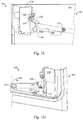
- FIG. 1G is a partial back view of an example indicator.
- FIG. 1H is a partial front view of an example indicator.
- FIG. 1I a partial perspective front view of an example indicator.
- FIG. 1J is a partial perspective front view of an example indicator.
- FIG. 1K is a partial back view of an example indicator.
- FIG. 1L is a partial back view of an example indicator.
- FIG. 2A is a partial perspective front view of an example indicator.
- FIG. 2B is a partial perspective front view of an example indicator.
- Printing systems may deposit printing fluid, such as ink, for example, on media or print media.
- printing systems may deposit other print substances on media, such as powder, for example, in a powder-based three-dimensional (3D) printer.
- the print media may be stored in a media tray, from which the printing system limy draw a sheet or portion of the print media for printing.
- the print media may be stored, a stack within the media tray.
- printing systems may have more than one media tray for storing multiple types or sizes of print media.
- Each of the media trays may have an external designation, shape, character, or other element to uniquely identify that particular tray to a user.
- the supply of print media within each media tray may be periodically filled or replaced when the supply reaches a certain level, or the supply is depleted.
- the media tray may include an indicator to inform a user of the level or quantity of the print media left within the media tray. It may further be desirable that the indicator be an external alert, or, in other words, be visible to a user from the exterior of the media tray, or the printing system.
- Such an external indicator may be a continuous indicator, in some situations.
- a continuous indicator may be graduated, or continuously follow the current level or quantity of the print media within the media tray and display such a quantity or level to an external user of the printing system. In some situations, interpreting a continuous indicator may be difficult or confusing.
- a graduated or continuous indicator may be subject to a user's interpretation, and multiple users using the same printing system may have different interpretations of the level of print media tell in the media tray based on any given external display of a continuous indicator.
- a continuous print media indicator may, to some users, appear to indicate that the media tray needs to be refilled. To other users, however, the continuous indicator may indicate that a sufficient quantity of print media remains in the tray and it does not need to be refilled.
- Implementations of the present disclosure provide an indicator for a media tray of a printing system.
- the indicator may be a binary indicator, or, in other words, may only have two indicator positions and may operate in an ON/OFF fashion, with no intermediate position.
- the indicator may provide an external indication to a user of the printing system that additional print media should be loaded into the media tray. Further, the external indication by the indicator of the level of print media left within the media tray ray not be subject to different interpretations by different users of the printing system.
- An example indicator may provide only one of two different indications at a time. A first indication may inform a user that the media tray still has a sufficient quantity of print media remaining within. The second indication may inform a user that the media tray needs additional print media to be loaded within. Any user of the printing system may be able to look to the example indicator of the media tray and see one of the two possible print media level indications and know whether the tray needs to be loaded or not.
- the media tray 102 may include an external portion 104 .
- the external portion 104 in some implementations, may be an exterior panel or all of the media tray 102 . Additionally, the outside surface of the external portion 104 may be visible to a user of the printing system, and in some situations, comprise an indicator window.
- the media tray 102 may receive print media 106 within the media tray 102 .
- the print media 106 in some implementations, may comprise multiple sheets paper. The printing system may draw the multiple sheets of paper from the media tray for printing.
- the printing system may draw a single sheet of paper from the stack of print media 106 at a time.
- the print media 106 may be powder use in a 3D printing system.
- the powder may be disposed within a media tray 102 that may support the powder and a three-dimensional object ask is being printed.
- the print media 106 in further implementations, may be supported by a lift plate within the media tray 102 .
- the lift plate in some implementations, may be biased in an upward direction, such that the lift plate constantly pushes the print media towards a pick element, roller, or portion of the printing system, wherein the pick element or portion is to draw a sheet of print media 106 from the print media 106 stack.
- the lift plate may be disposed at continuously different heights within the media tray 102 , depending on the quantity of print media 106 in the tray 102 . For example, a full stack of print media 106 may push the lift plate further down into the media tray 102 than half a stack of print media 106 . Thus, the lift plate may move further in the upward direction, as each sheet of print media 106 is removed by the pick element, roller, or portion from the stack of print media 106 .
- the example indicator 100 may comprise an arm 108 , a latch 116 , and an indicator plate 118 , in some implementations.
- the arm 108 may be a rigid strut or beam having a first end 119 and a second end 120 , in some implementations.
- the arm 108 may be pivotally engaged with the media tray 102 , or a lift plate within the media tray 102 .
- the arm 108 may be pivotally disposed within the media tray 102 , and compromise a pivot 121 disposed longitudinally along the length of the arm 108 in between the first end 119 and the second end 120 .
- the pivot 121 may be disposed on the arm 108 such that, if the first end 119 were to move in a first direction, for example, a downward direction 110 , the arm 108 would rotate in a corresponding direction 112 about the pivot 121 , and the second end 120 may move in a direction opposite to the downward direction 110 , such as an upward direction 114 .
- the arm 108 may rotate about the pivot 121 in a corresponding direction, and the second end 120 may move in a direction opposite to the direction of movement of the first end 119 .
- the arm 108 may be pivotally engaged with the print media 106 itself within the media tray 102 , or, in some implementations, with a lift plate supporting the print media 106 within the media tray 102 .
- the arm 108 may be coupled to or engaged with the lift plate such that the first end 119 of the arm 108 travels with the lift plate, or in a corresponding manner as the lift plate.
- print media 106 may push the lift plate in a downward direction upon being loaded into the media tray 102 , or upon the media tray 102 otherwise receiving the print media 106 .
- the lift plate may concurrently move the first end 119 of the arm 108 in a corresponding downward direction 110 .
- the lilt plate may move either incrementally or continuously in an upward direction, thereby also causing the first end 119 of the arm 108 to move in a corresponding upward direction.
- the first end 119 of the arm 108 may be directly engaged with the print media 106 in some implementations, instead of with a lift plate.
- the print media 106 may directly push the first end 119 of the arm 108 in a downward direction upon being loaded into the media tray 102 , and the first end 119 of the aim 108 may move in an opposite, upward direction upon print media 106 being removed from the media tray 102 .
- the first end 119 of the arm 108 may be directly biased in an upward direction such that the first end 119 pushes the print media 106 in the upward direction upon print media 106 being removed from the stack of print media 106 within the media tray 102 .
- the example indicator 100 may comprise a latch 116 and an indicator plate 118 .
- the indicator plate may be a movable component relative to the meal tray 102 , and comprise a latch post 122 .
- the indicator plate 118 may be movably coupled to the media tray 102 , or, in some implementations, the indicator plate 118 may be disposed within, and therefore movable within, a track, slot, or other orifice or aperture in the media tray 102 .
- the indicator plate 118 may be switchably disposed in one of a raised position and a lowered position.
- the indicator plate 118 may be slidably coupled to or engaged with the media tray 102 such that the indicator plate 118 may slide from the raised position to the lowered position, and vice versa.
- the indicator plate 118 may be slidably engaged with an exterior panel 104 of the media tray 102 .
- the indicator plate 118 tray be coupled to or engaged with the exterior panel 104 of the media tray 102 such that, when disposed in the lowered position, a portion or all of the indicator plate 118 may be visible to the exterior of the media tray 102 or the printing system.
- the indicator plate 118 may comprise a color, at least in part, other than the same or a similar color as the exterior of the media tray 102 or the printing system. In yet further implementations, the indicator plate 118 may comprise a color that contrasts with the exterior color of the media tray 102 or the printing system, so that the contrasting colors increase the visibility of the indicator plate 118 when in the lowered position.
- the example indicator 100 may further comprise a latch 116 .
- the latch 116 may be coupled to or engaged with each of the arm 108 and the indicator plate 118 .
- the latch 116 may be pivotally coupled to the media tray 102 such that the latch 116 may toggle or pivot relative to the media tray 102 , between a latched position and a released position.
- the latch 116 may be biased towards the latched position.
- the latch 116 may be biased towards the latched position by a resilient bias member, such as a spring or torsion spring.
- the latch 116 may be biased towards the latched position by gravity and having, an unbalanced pivot point.
- the latch 116 may comprise a latch portion 124 to engage with the latch post 122 of the indicator plate 118 , in some implementations.
- the latch portion 124 may include complementary geometry, such as a slot, shelf or channel, for example, to cradle or hold the latch post 122 in the latched position.
- an example indicator is illustrated wherein the indicator plate 118 is disposed in the raised position.
- the latch 116 may be disposed in the latched position, and therefore may support the indicator plate 118 in the raised position.
- the latch 116 may support the indicator plate 118 in the raised position by the latching portion 124 of the latch 11 engaging with the latch post 122 of the indicator plate 118 such that the latch post 122 fully rests upon the latching portion 124 , and the latch 116 can, therefore, support the entire weight of the indicator plate 118 .
- the arm 108 may comprise a pivot tab 130 to engage with a pivot surface 132 of the latch 116 .
- the pivot tab 130 may be a protrusion that extends laterally, or substantially orthogonally, from the longitudinal axis of the arm 108 .
- the pivot tab 130 troy in some implementations, be a unitary part of the arm 108 , or, in other implementations, the pivot tab 130 may be a separate component that is assembled to the arm 108 .
- the pivot tab 130 may be disposed on the second end 120 of the arm 108 and, thus, move with the second end 120 of the arm 108 .
- the second end 120 may move in a downward direction, thus also lowering or moving the pivot tab 130 in a downward direction 128 .
- the pivot tab 130 may be disposed along or spaced along the length of the arm 108 at an appropriate location such that, upon moving in a downward direction such as direction 128 , the pivot tab 130 may contact the pivot surface 132 of the latch 116 .
- FIG. 1E a partial back view of an example indicator 100 is illustrated.
- FIG. 1F a partial front view of the example indicator 100 is illustrated.
- FIGS. 1E-F an example indicator 100 is illustrated wherein the indicator plate 118 is still disposed in the raised position, and the arm 108 has rotated along direction 126 .
- the first end 119 of the arm 108 may have moved in an upward direction as depicted in FIG.
- FIG. 1G a partial back view of an example indicator 100 illustrated.
- FIG. 1H a partial front view of the example indicator 100 is illustrated.
- an example indicator 100 is illustrated wherein the arm 108 has continued to rotate along direction 126 , the latch 116 has pivoted to the released position, and the indicator plate 118 has fallen or slid to the lowered position.
- the arm 108 may haw continued to rotate along direction 126 due to print media continuing to be removed from the media tray 102 and, therefore, causing the first end 119 of the arm 108 to continue to move in the upward direction.
- the arm 108 may have moved along, the direction 126 far enough to cause the latch 116 to release the indicator plate 118 due to a certain, or specific quantity, or predetermined amount of print media remaining within the media tray 102 .
- the second end 120 of the arm 108 and thus the pivot tab 130 , has continued to move in the downward direction 128 .
- the pivot tab 130 therefore, has pushed upon the pivot surface 132 of the latch 116 such that the latch 116 has pivoted about its pivot point 133 .
- the pivot tab 130 has cawed the latch 116 to pivot such that the latch portion 124 has translated in a direction 129 , away from the latch post 122 of the indicator plate 118 . As illustrated in FIG.
- the pivot tab 130 has continued in the direction 128 , pushing on pivot surface 132 so that the latch portion 124 has completely disengaged from the latch post 122 .
- the latch 116 Upon disengagement of the latch post 122 with the latching portion 124 , the latch 116 has fully pivoted from the latched position to the released position, and the indicator plate 118 is no longer supported in the raised position by the latch 116 .
- the latch 116 has released the indicator plate 118 to slide in a direction 134 to the lowered position.
- the indicator plate 118 may be supported in the raised position until a predetermined, or specific amount of print media 106 is removed from the media tray, thereby moving the arm 108 a sufficient amount to contact and pivot the latch 116 to a degree where the latch 116 releases the indicator plate 118 .
- FIGS. 1I-J partial perspective views of an example indicator 100 disposed within a media tray 102 are illustrated.
- the media tray 102 may have an exterior panel 104 comprising an indicator window 136 , in some implementations.
- the indicator plate 118 may be visible to the exterior of the media tray 102 or printing system through the window 136 when in the lowered position. Further, the indicator plate 118 may not be visible to the exterior of the media tray 102 or printing system through the indicator window 136 when in the raised position
- FIG. 1I may represent the situation illustrated in FIGS. C-F, where the indicator plate 118 is disposed in the raised position, supported by the latch 116 . Further, FIG. 1J may represent the situation illustrated in FIGS.
- the hitch 116 has pivoted from the latched position to the released position, and the indicator plate 118 has moved from the raised position to the lowered position.
- the indicator plate 118 may now be visible through the window 136 to an external user, signifying to the user that the predetermined, or specific amount of print media is remaining within the media tray 102 , and that additional print media 106 should be added to the tray 102 .
- FIG. 1K a partial back view of an example indicator 100 is illustrated, wherein the arm 108 has rotated along direction 112 , after the indicator plate 118 has moved from the raised position to the lowered position.
- the arm 108 may rotate along direction 112 due to the first end 119 of the arm 108 moving in a downward direction, such as direction 110 , for example.
- the first end 119 may move in a downward direction, in some implementations, due to additional print media 106 being disposed within or added to the media tray 102 .
- a user may refill the media tray 102 , thereby moving the first end 119 of the arm 108 in a downward direction 110 , and the second end 120 of the arm 108 in an upward direction, such as direction 114 .
- the latch post 122 of the indicator plate 118 may be engaged with, or resting upon, in some implementations, a surface of the second end 120 , such that, as the second end 120 moves in upward direction 114 , the second end 120 pushes the latch post 122 , and thus the indicator plate 118 upwards towards the raised position.
- FIG. 1L a partial back view of an example indicator 100 is illustrated, wherein the arm 108 has continued to rotate along direction 112 , thereby pushing the latch post 122 in an upwards direction 114 so that the latch post 122 comes into contact with the latching portion 124 of the latch 116 .
- the latch post 122 of the indicator plate 118 may contact and engage with a surface or feature of the latching portion 124 of the latch 116 such that the post 122 pushes the latching portion 124 in a lateral direction, such as direction 129 , for example.
- the latch post 122 may continue to push the latching portion 124 along the lateral direction such that the latch 116 pivots from the latched position back to the released position. Once the latch 116 reaches the released position, the latch post 122 may continue moving in the upward direction until it has moved beyond and stopped contact with the surface or feature of the latching portion 124 . In some implementations, the latch post 122 may stop contact with the latching portion 124 once the indicator plate 118 is back in the raised position. Additionally, the latch post 122 , in some implementations, may stop contact with the hitching portion 124 upon a predetermined amount or quantity of print media 106 being loaded into the media tray 102 .
- the latch 116 may, once again, pivot from the released position back to the latched position due to the latch 116 being biased in the latched direction.
- the latch post 122 may, again, be engaged with the latching portion 124 so that the latch 116 supports the indicator plate 118 in the raised position, as illustrated in FIGS. 1C-D .
- the arm 108 may push the indicator plate 118 back up to the raised position, where the latch post 122 may pivot the latch 116 from the latched position to the released position so that the latch post 122 may move past the latching portion 124 of the latch 116 , and wherein the latch 116 may then pivot back to the latched position to support the indicator plate 118 in the raised position.
- Example indicator 200 may be similar to example indicator 100 . Further, the similarly named elements of example indicator 200 may be similar in function and/or structure to the elements of example indicator 100 , as they are described above.
- the media tray 202 may have an exterior panel 204 comprising an indicator window 236 , in some implementations.
- the indicator window 236 may comprise the shape of a symbol or character to identify the media tray 202 and differentiate the media tray 202 from other media trays disposed within the same printing system.
- the indicator window 236 may comprise the shape of an alphanumeric character, such as a letter or number in order to identify the medic tray 202 . Additionally, an indicator plate may be visible to the exterior of the media tray 202 when the indicator plate is in a lowered position, which may be behind the indicator window 236 . Further, the indicator plate may be disposed behind the indicator window 236 when in the lowered position such that the character or symbol is visible to the exterior of the media tray 202 .
Landscapes
- Engineering & Computer Science (AREA)
- Mechanical Engineering (AREA)
- Chemical & Material Sciences (AREA)
- Materials Engineering (AREA)
- Physics & Mathematics (AREA)
- Manufacturing & Machinery (AREA)
- Optics & Photonics (AREA)
- General Physics & Mathematics (AREA)
- Sheets, Magazines, And Separation Thereof (AREA)
Abstract
Description
Claims (14)
Applications Claiming Priority (1)
| Application Number | Priority Date | Filing Date | Title |
|---|---|---|---|
| PCT/US2015/064078 WO2017095446A1 (en) | 2015-12-04 | 2015-12-04 | Indicators |
Publications (2)
| Publication Number | Publication Date |
|---|---|
| US20180257298A1 US20180257298A1 (en) | 2018-09-13 |
| US10960604B2 true US10960604B2 (en) | 2021-03-30 |
Family
ID=58797687
Family Applications (1)
| Application Number | Title | Priority Date | Filing Date |
|---|---|---|---|
| US15/759,349 Expired - Fee Related US10960604B2 (en) | 2015-12-04 | 2015-12-04 | Indicators |
Country Status (4)
| Country | Link |
|---|---|
| US (1) | US10960604B2 (en) |
| EP (1) | EP3337668B1 (en) |
| CN (1) | CN108349271B (en) |
| WO (1) | WO2017095446A1 (en) |
Families Citing this family (1)
| Publication number | Priority date | Publication date | Assignee | Title |
|---|---|---|---|---|
| US10730709B2 (en) * | 2015-09-11 | 2020-08-04 | Hewlett-Packard Development Company, L.P. | Media tray assemblies with indicators |
Citations (14)
| Publication number | Priority date | Publication date | Assignee | Title |
|---|---|---|---|---|
| US4566547A (en) | 1981-04-10 | 1986-01-28 | Canon Kabushiki Kaisha | Remaining amount indicator |
| US5236348A (en) | 1992-10-06 | 1993-08-17 | Hewlett-Packard Company | Printer paper status indicator |
| JPH07215529A (en) | 1994-02-08 | 1995-08-15 | Canon Inc | Sheet stacking apparatus and image forming apparatus |
| JPH10245139A (en) * | 1997-03-07 | 1998-09-14 | Canon Inc | Sheet storage device and image processing device |
| US6247695B1 (en) | 1998-12-23 | 2001-06-19 | Xerox Corporation | Multiple zone stack height sensor for high capacity feeder |
| US6252654B1 (en) | 1998-10-23 | 2001-06-26 | Fuji Photo Film Co., Ltd. | Indicating device used for a paper cassette and for indicating a remaining amount of recording papers |
| JP2007191264A (en) * | 2006-01-19 | 2007-08-02 | Kyocera Mita Corp | Paper storage device |
| JP2008133061A (en) * | 2006-11-27 | 2008-06-12 | Kyocera Mita Corp | Paper feeder |
| US20080143773A1 (en) | 2004-09-30 | 2008-06-19 | Lexmark International, Inc. | Print media detection in an imaging apparatus |
| US20130001871A1 (en) | 2011-06-29 | 2013-01-03 | Hon Hai Precision Industry Co., Ltd. | Media level indicator and printer having same |
| US20130161899A1 (en) | 2011-12-21 | 2013-06-27 | Shigeyuki Ito | Sheet amount indicator and image forming apparatus |
| US20150239265A1 (en) | 2012-09-26 | 2015-08-27 | Hewlett-Packard Development Company, L.P. | Printer paper tray |
| US20170003635A1 (en) * | 2015-07-02 | 2017-01-05 | Canon Kabushiki Kaisha | Sheet supporting device |
| US20190077620A1 (en) * | 2015-09-11 | 2019-03-14 | Hewlett-Packard Development Company, L.P. | Media tray assemblies with indicators |
Family Cites Families (5)
| Publication number | Priority date | Publication date | Assignee | Title |
|---|---|---|---|---|
| JPS62191345A (en) * | 1986-02-18 | 1987-08-21 | Nec Corp | Form feeding cassette for sheet feeder |
| CN2249165Y (en) * | 1996-03-12 | 1997-03-12 | 明碁电脑股份有限公司 | Tray paper storage display device |
| JP3952500B2 (en) * | 2002-09-17 | 2007-08-01 | 富士ゼロックス株式会社 | Paper feeding cassette and image forming apparatus |
| KR20050066379A (en) * | 2003-12-26 | 2005-06-30 | 엘지엔시스(주) | Device for sensing residue paper for printer |
| US7350895B2 (en) * | 2005-04-20 | 2008-04-01 | John Tiedge | Printing container fill indicator |
-
2015
- 2015-12-04 WO PCT/US2015/064078 patent/WO2017095446A1/en not_active Ceased
- 2015-12-04 CN CN201580084013.4A patent/CN108349271B/en not_active Expired - Fee Related
- 2015-12-04 US US15/759,349 patent/US10960604B2/en not_active Expired - Fee Related
- 2015-12-04 EP EP15909958.9A patent/EP3337668B1/en not_active Not-in-force
Patent Citations (15)
| Publication number | Priority date | Publication date | Assignee | Title |
|---|---|---|---|---|
| US4566547A (en) | 1981-04-10 | 1986-01-28 | Canon Kabushiki Kaisha | Remaining amount indicator |
| US5236348A (en) | 1992-10-06 | 1993-08-17 | Hewlett-Packard Company | Printer paper status indicator |
| JPH07215529A (en) | 1994-02-08 | 1995-08-15 | Canon Inc | Sheet stacking apparatus and image forming apparatus |
| JPH10245139A (en) * | 1997-03-07 | 1998-09-14 | Canon Inc | Sheet storage device and image processing device |
| US6252654B1 (en) | 1998-10-23 | 2001-06-26 | Fuji Photo Film Co., Ltd. | Indicating device used for a paper cassette and for indicating a remaining amount of recording papers |
| US6247695B1 (en) | 1998-12-23 | 2001-06-19 | Xerox Corporation | Multiple zone stack height sensor for high capacity feeder |
| US20080143773A1 (en) | 2004-09-30 | 2008-06-19 | Lexmark International, Inc. | Print media detection in an imaging apparatus |
| JP2007191264A (en) * | 2006-01-19 | 2007-08-02 | Kyocera Mita Corp | Paper storage device |
| JP2008133061A (en) * | 2006-11-27 | 2008-06-12 | Kyocera Mita Corp | Paper feeder |
| US20130001871A1 (en) | 2011-06-29 | 2013-01-03 | Hon Hai Precision Industry Co., Ltd. | Media level indicator and printer having same |
| US8393613B2 (en) | 2011-06-29 | 2013-03-12 | Hon Hai Precision Industry Co., Ltd. | Media level indicator and printer having same |
| US20130161899A1 (en) | 2011-12-21 | 2013-06-27 | Shigeyuki Ito | Sheet amount indicator and image forming apparatus |
| US20150239265A1 (en) | 2012-09-26 | 2015-08-27 | Hewlett-Packard Development Company, L.P. | Printer paper tray |
| US20170003635A1 (en) * | 2015-07-02 | 2017-01-05 | Canon Kabushiki Kaisha | Sheet supporting device |
| US20190077620A1 (en) * | 2015-09-11 | 2019-03-14 | Hewlett-Packard Development Company, L.P. | Media tray assemblies with indicators |
Also Published As
| Publication number | Publication date |
|---|---|
| WO2017095446A1 (en) | 2017-06-08 |
| CN108349271B (en) | 2020-10-02 |
| EP3337668A1 (en) | 2018-06-27 |
| EP3337668A4 (en) | 2019-05-15 |
| EP3337668B1 (en) | 2021-01-27 |
| US20180257298A1 (en) | 2018-09-13 |
| CN108349271A (en) | 2018-07-31 |
Similar Documents
| Publication | Publication Date | Title |
|---|---|---|
| US10960604B2 (en) | Indicators | |
| NO802482L (en) | CONTAINER DEVICE FOR SETTING ON A PLAN AREA | |
| US20170092161A1 (en) | Nameplates and locking assemblies thereof | |
| CN107901813A (en) | A kind of vehicle-mounted cup holder | |
| EP4021211A1 (en) | Print surface positioning mechanisms for printer | |
| WO2012115735A3 (en) | Holder for beverage containers | |
| US420107A (en) | Cabinet for hotel stationery | |
| US2782539A (en) | Rotatable calendar stand | |
| US10730709B2 (en) | Media tray assemblies with indicators | |
| CN207411717U (en) | The storage box of locking locking apparatus | |
| CN203290577U (en) | Sliding goods shelf | |
| US1065112A (en) | Label-holder. | |
| KR101799916B1 (en) | Multipurpose Pencil Vase | |
| KR200479875Y1 (en) | Compasses and ruler in one | |
| CN203847945U (en) | Independent tripod supporting photographic equipment | |
| US20090050647A1 (en) | Sheet Product Dispenser With Retention Member | |
| CN102294901B (en) | Paper loading structure of embedded minitype printer | |
| KR20210056666A (en) | guide glasses | |
| KR200477806Y1 (en) | A calendar stand for desk including holders for smart devices | |
| US2568565A (en) | Sheet holder | |
| US1129557A (en) | Measuring-scale. | |
| US969590A (en) | Foot-rule pocket. | |
| CN206058850U (en) | A kind of publicity exhibition board, upset table, motor train compartment | |
| CN202147932U (en) | Containing device | |
| US2049079A (en) | Advertising device |
Legal Events
| Date | Code | Title | Description |
|---|---|---|---|
| FEPP | Fee payment procedure |
Free format text: ENTITY STATUS SET TO UNDISCOUNTED (ORIGINAL EVENT CODE: BIG.); ENTITY STATUS OF PATENT OWNER: LARGE ENTITY |
|
| AS | Assignment |
Owner name: HEWLETT-PACKARD DEVELOPMENT COMPANY, L.P., TEXAS Free format text: ASSIGNMENT OF ASSIGNORS INTEREST;ASSIGNOR:MILES, MICHAEL DUFFIELD;REEL/FRAME:045757/0391 Effective date: 20151203 |
|
| STPP | Information on status: patent application and granting procedure in general |
Free format text: DOCKETED NEW CASE - READY FOR EXAMINATION |
|
| STPP | Information on status: patent application and granting procedure in general |
Free format text: NON FINAL ACTION MAILED |
|
| STPP | Information on status: patent application and granting procedure in general |
Free format text: RESPONSE TO NON-FINAL OFFICE ACTION ENTERED AND FORWARDED TO EXAMINER |
|
| STPP | Information on status: patent application and granting procedure in general |
Free format text: NOTICE OF ALLOWANCE MAILED -- APPLICATION RECEIVED IN OFFICE OF PUBLICATIONS |
|
| STPP | Information on status: patent application and granting procedure in general |
Free format text: PUBLICATIONS -- ISSUE FEE PAYMENT VERIFIED |
|
| STCF | Information on status: patent grant |
Free format text: PATENTED CASE |
|
| FEPP | Fee payment procedure |
Free format text: MAINTENANCE FEE REMINDER MAILED (ORIGINAL EVENT CODE: REM.); ENTITY STATUS OF PATENT OWNER: LARGE ENTITY |
|
| LAPS | Lapse for failure to pay maintenance fees |
Free format text: PATENT EXPIRED FOR FAILURE TO PAY MAINTENANCE FEES (ORIGINAL EVENT CODE: EXP.); ENTITY STATUS OF PATENT OWNER: LARGE ENTITY |
|
| STCH | Information on status: patent discontinuation |
Free format text: PATENT EXPIRED DUE TO NONPAYMENT OF MAINTENANCE FEES UNDER 37 CFR 1.362 |
|
| FP | Lapsed due to failure to pay maintenance fee |
Effective date: 20250330 |