US10951126B2 - System and method for operating a system - Google Patents
System and method for operating a system Download PDFInfo
- Publication number
- US10951126B2 US10951126B2 US16/335,753 US201716335753A US10951126B2 US 10951126 B2 US10951126 B2 US 10951126B2 US 201716335753 A US201716335753 A US 201716335753A US 10951126 B2 US10951126 B2 US 10951126B2
- Authority
- US
- United States
- Prior art keywords
- rectifier
- side connection
- converter
- voltage side
- inverter
- Prior art date
- Legal status (The legal status is an assumption and is not a legal conclusion. Google has not performed a legal analysis and makes no representation as to the accuracy of the status listed.)
- Active, expires
Links
- 238000000034 method Methods 0.000 title claims abstract description 11
- 239000004065 semiconductor Substances 0.000 claims abstract description 20
- 238000002347 injection Methods 0.000 claims description 6
- 239000007924 injection Substances 0.000 claims description 6
- 239000003990 capacitor Substances 0.000 description 10
- 239000013256 coordination polymer Substances 0.000 description 5
- 230000003247 decreasing effect Effects 0.000 description 1
- 238000007599 discharging Methods 0.000 description 1
- 230000009977 dual effect Effects 0.000 description 1
- 239000002184 metal Substances 0.000 description 1
- 230000005855 radiation Effects 0.000 description 1
- 238000004804 winding Methods 0.000 description 1
Images


Classifications
-
- H—ELECTRICITY
- H02—GENERATION; CONVERSION OR DISTRIBUTION OF ELECTRIC POWER
- H02M—APPARATUS FOR CONVERSION BETWEEN AC AND AC, BETWEEN AC AND DC, OR BETWEEN DC AND DC, AND FOR USE WITH MAINS OR SIMILAR POWER SUPPLY SYSTEMS; CONVERSION OF DC OR AC INPUT POWER INTO SURGE OUTPUT POWER; CONTROL OR REGULATION THEREOF
- H02M5/00—Conversion of ac power input into ac power output, e.g. for change of voltage, for change of frequency, for change of number of phases
- H02M5/40—Conversion of ac power input into ac power output, e.g. for change of voltage, for change of frequency, for change of number of phases with intermediate conversion into dc
- H02M5/42—Conversion of ac power input into ac power output, e.g. for change of voltage, for change of frequency, for change of number of phases with intermediate conversion into dc by static converters
- H02M5/44—Conversion of ac power input into ac power output, e.g. for change of voltage, for change of frequency, for change of number of phases with intermediate conversion into dc by static converters using discharge tubes or semiconductor devices to convert the intermediate dc into ac
- H02M5/453—Conversion of ac power input into ac power output, e.g. for change of voltage, for change of frequency, for change of number of phases with intermediate conversion into dc by static converters using discharge tubes or semiconductor devices to convert the intermediate dc into ac using devices of a triode or transistor type requiring continuous application of a control signal
- H02M5/458—Conversion of ac power input into ac power output, e.g. for change of voltage, for change of frequency, for change of number of phases with intermediate conversion into dc by static converters using discharge tubes or semiconductor devices to convert the intermediate dc into ac using devices of a triode or transistor type requiring continuous application of a control signal using semiconductor devices only
-
- H—ELECTRICITY
- H02—GENERATION; CONVERSION OR DISTRIBUTION OF ELECTRIC POWER
- H02J—CIRCUIT ARRANGEMENTS OR SYSTEMS FOR SUPPLYING OR DISTRIBUTING ELECTRIC POWER; SYSTEMS FOR STORING ELECTRIC ENERGY
- H02J7/00—Circuit arrangements for charging or depolarising batteries or for supplying loads from batteries
- H02J7/007—Regulation of charging or discharging current or voltage
- H02J7/0071—Regulation of charging or discharging current or voltage with a programmable schedule
-
- H02J7/0072—
-
- H—ELECTRICITY
- H02—GENERATION; CONVERSION OR DISTRIBUTION OF ELECTRIC POWER
- H02M—APPARATUS FOR CONVERSION BETWEEN AC AND AC, BETWEEN AC AND DC, OR BETWEEN DC AND DC, AND FOR USE WITH MAINS OR SIMILAR POWER SUPPLY SYSTEMS; CONVERSION OF DC OR AC INPUT POWER INTO SURGE OUTPUT POWER; CONTROL OR REGULATION THEREOF
- H02M3/00—Conversion of dc power input into dc power output
- H02M3/22—Conversion of dc power input into dc power output with intermediate conversion into ac
- H02M3/24—Conversion of dc power input into dc power output with intermediate conversion into ac by static converters
- H02M3/28—Conversion of dc power input into dc power output with intermediate conversion into ac by static converters using discharge tubes with control electrode or semiconductor devices with control electrode to produce the intermediate ac
- H02M3/325—Conversion of dc power input into dc power output with intermediate conversion into ac by static converters using discharge tubes with control electrode or semiconductor devices with control electrode to produce the intermediate ac using devices of a triode or a transistor type requiring continuous application of a control signal
- H02M3/335—Conversion of dc power input into dc power output with intermediate conversion into ac by static converters using discharge tubes with control electrode or semiconductor devices with control electrode to produce the intermediate ac using devices of a triode or a transistor type requiring continuous application of a control signal using semiconductor devices only
- H02M3/33569—Conversion of dc power input into dc power output with intermediate conversion into ac by static converters using discharge tubes with control electrode or semiconductor devices with control electrode to produce the intermediate ac using devices of a triode or a transistor type requiring continuous application of a control signal using semiconductor devices only having several active switching elements
- H02M3/33576—Conversion of dc power input into dc power output with intermediate conversion into ac by static converters using discharge tubes with control electrode or semiconductor devices with control electrode to produce the intermediate ac using devices of a triode or a transistor type requiring continuous application of a control signal using semiconductor devices only having several active switching elements having at least one active switching element at the secondary side of an isolation transformer
-
- H—ELECTRICITY
- H02—GENERATION; CONVERSION OR DISTRIBUTION OF ELECTRIC POWER
- H02M—APPARATUS FOR CONVERSION BETWEEN AC AND AC, BETWEEN AC AND DC, OR BETWEEN DC AND DC, AND FOR USE WITH MAINS OR SIMILAR POWER SUPPLY SYSTEMS; CONVERSION OF DC OR AC INPUT POWER INTO SURGE OUTPUT POWER; CONTROL OR REGULATION THEREOF
- H02M5/00—Conversion of ac power input into ac power output, e.g. for change of voltage, for change of frequency, for change of number of phases
- H02M5/40—Conversion of ac power input into ac power output, e.g. for change of voltage, for change of frequency, for change of number of phases with intermediate conversion into dc
- H02M5/42—Conversion of ac power input into ac power output, e.g. for change of voltage, for change of frequency, for change of number of phases with intermediate conversion into dc by static converters
-
- H—ELECTRICITY
- H02—GENERATION; CONVERSION OR DISTRIBUTION OF ELECTRIC POWER
- H02M—APPARATUS FOR CONVERSION BETWEEN AC AND AC, BETWEEN AC AND DC, OR BETWEEN DC AND DC, AND FOR USE WITH MAINS OR SIMILAR POWER SUPPLY SYSTEMS; CONVERSION OF DC OR AC INPUT POWER INTO SURGE OUTPUT POWER; CONTROL OR REGULATION THEREOF
- H02M7/00—Conversion of ac power input into dc power output; Conversion of dc power input into ac power output
- H02M7/003—Constructional details, e.g. physical layout, assembly, wiring or busbar connections
-
- H—ELECTRICITY
- H02—GENERATION; CONVERSION OR DISTRIBUTION OF ELECTRIC POWER
- H02P—CONTROL OR REGULATION OF ELECTRIC MOTORS, ELECTRIC GENERATORS OR DYNAMO-ELECTRIC CONVERTERS; CONTROLLING TRANSFORMERS, REACTORS OR CHOKE COILS
- H02P21/00—Arrangements or methods for the control of electric machines by vector control, e.g. by control of field orientation
- H02P21/22—Current control, e.g. using a current control loop
-
- H—ELECTRICITY
- H02—GENERATION; CONVERSION OR DISTRIBUTION OF ELECTRIC POWER
- H02P—CONTROL OR REGULATION OF ELECTRIC MOTORS, ELECTRIC GENERATORS OR DYNAMO-ELECTRIC CONVERTERS; CONTROLLING TRANSFORMERS, REACTORS OR CHOKE COILS
- H02P27/00—Arrangements or methods for the control of AC motors characterised by the kind of supply voltage
- H02P27/04—Arrangements or methods for the control of AC motors characterised by the kind of supply voltage using variable-frequency supply voltage, e.g. inverter or converter supply voltage
- H02P27/06—Arrangements or methods for the control of AC motors characterised by the kind of supply voltage using variable-frequency supply voltage, e.g. inverter or converter supply voltage using dc to ac converters or inverters
- H02P27/08—Arrangements or methods for the control of AC motors characterised by the kind of supply voltage using variable-frequency supply voltage, e.g. inverter or converter supply voltage using dc to ac converters or inverters with pulse width modulation
-
- H—ELECTRICITY
- H02—GENERATION; CONVERSION OR DISTRIBUTION OF ELECTRIC POWER
- H02M—APPARATUS FOR CONVERSION BETWEEN AC AND AC, BETWEEN AC AND DC, OR BETWEEN DC AND DC, AND FOR USE WITH MAINS OR SIMILAR POWER SUPPLY SYSTEMS; CONVERSION OF DC OR AC INPUT POWER INTO SURGE OUTPUT POWER; CONTROL OR REGULATION THEREOF
- H02M1/00—Details of apparatus for conversion
- H02M1/0003—Details of control, feedback or regulation circuits
- H02M1/0009—Devices or circuits for detecting current in a converter
-
- H—ELECTRICITY
- H02—GENERATION; CONVERSION OR DISTRIBUTION OF ELECTRIC POWER
- H02M—APPARATUS FOR CONVERSION BETWEEN AC AND AC, BETWEEN AC AND DC, OR BETWEEN DC AND DC, AND FOR USE WITH MAINS OR SIMILAR POWER SUPPLY SYSTEMS; CONVERSION OF DC OR AC INPUT POWER INTO SURGE OUTPUT POWER; CONTROL OR REGULATION THEREOF
- H02M1/00—Details of apparatus for conversion
- H02M1/0003—Details of control, feedback or regulation circuits
- H02M1/0016—Control circuits providing compensation of output voltage deviations using feedforward of disturbance parameters
- H02M1/0019—Control circuits providing compensation of output voltage deviations using feedforward of disturbance parameters the disturbance parameters being load current fluctuations
-
- H02M2001/0009—
-
- H02M2001/0019—
-
- H02M2003/1586—
-
- H—ELECTRICITY
- H02—GENERATION; CONVERSION OR DISTRIBUTION OF ELECTRIC POWER
- H02M—APPARATUS FOR CONVERSION BETWEEN AC AND AC, BETWEEN AC AND DC, OR BETWEEN DC AND DC, AND FOR USE WITH MAINS OR SIMILAR POWER SUPPLY SYSTEMS; CONVERSION OF DC OR AC INPUT POWER INTO SURGE OUTPUT POWER; CONTROL OR REGULATION THEREOF
- H02M3/00—Conversion of dc power input into dc power output
- H02M3/02—Conversion of dc power input into dc power output without intermediate conversion into ac
- H02M3/04—Conversion of dc power input into dc power output without intermediate conversion into ac by static converters
- H02M3/10—Conversion of dc power input into dc power output without intermediate conversion into ac by static converters using discharge tubes with control electrode or semiconductor devices with control electrode
- H02M3/145—Conversion of dc power input into dc power output without intermediate conversion into ac by static converters using discharge tubes with control electrode or semiconductor devices with control electrode using devices of a triode or transistor type requiring continuous application of a control signal
- H02M3/155—Conversion of dc power input into dc power output without intermediate conversion into ac by static converters using discharge tubes with control electrode or semiconductor devices with control electrode using devices of a triode or transistor type requiring continuous application of a control signal using semiconductor devices only
- H02M3/156—Conversion of dc power input into dc power output without intermediate conversion into ac by static converters using discharge tubes with control electrode or semiconductor devices with control electrode using devices of a triode or transistor type requiring continuous application of a control signal using semiconductor devices only with automatic control of output voltage or current, e.g. switching regulators
- H02M3/158—Conversion of dc power input into dc power output without intermediate conversion into ac by static converters using discharge tubes with control electrode or semiconductor devices with control electrode using devices of a triode or transistor type requiring continuous application of a control signal using semiconductor devices only with automatic control of output voltage or current, e.g. switching regulators including plural semiconductor devices as final control devices for a single load
- H02M3/1582—Buck-boost converters
-
- H—ELECTRICITY
- H02—GENERATION; CONVERSION OR DISTRIBUTION OF ELECTRIC POWER
- H02M—APPARATUS FOR CONVERSION BETWEEN AC AND AC, BETWEEN AC AND DC, OR BETWEEN DC AND DC, AND FOR USE WITH MAINS OR SIMILAR POWER SUPPLY SYSTEMS; CONVERSION OF DC OR AC INPUT POWER INTO SURGE OUTPUT POWER; CONTROL OR REGULATION THEREOF
- H02M3/00—Conversion of dc power input into dc power output
- H02M3/02—Conversion of dc power input into dc power output without intermediate conversion into ac
- H02M3/04—Conversion of dc power input into dc power output without intermediate conversion into ac by static converters
- H02M3/10—Conversion of dc power input into dc power output without intermediate conversion into ac by static converters using discharge tubes with control electrode or semiconductor devices with control electrode
- H02M3/145—Conversion of dc power input into dc power output without intermediate conversion into ac by static converters using discharge tubes with control electrode or semiconductor devices with control electrode using devices of a triode or transistor type requiring continuous application of a control signal
- H02M3/155—Conversion of dc power input into dc power output without intermediate conversion into ac by static converters using discharge tubes with control electrode or semiconductor devices with control electrode using devices of a triode or transistor type requiring continuous application of a control signal using semiconductor devices only
- H02M3/156—Conversion of dc power input into dc power output without intermediate conversion into ac by static converters using discharge tubes with control electrode or semiconductor devices with control electrode using devices of a triode or transistor type requiring continuous application of a control signal using semiconductor devices only with automatic control of output voltage or current, e.g. switching regulators
- H02M3/158—Conversion of dc power input into dc power output without intermediate conversion into ac by static converters using discharge tubes with control electrode or semiconductor devices with control electrode using devices of a triode or transistor type requiring continuous application of a control signal using semiconductor devices only with automatic control of output voltage or current, e.g. switching regulators including plural semiconductor devices as final control devices for a single load
- H02M3/1584—Conversion of dc power input into dc power output without intermediate conversion into ac by static converters using discharge tubes with control electrode or semiconductor devices with control electrode using devices of a triode or transistor type requiring continuous application of a control signal using semiconductor devices only with automatic control of output voltage or current, e.g. switching regulators including plural semiconductor devices as final control devices for a single load with a plurality of power processing stages connected in parallel
- H02M3/1586—Conversion of dc power input into dc power output without intermediate conversion into ac by static converters using discharge tubes with control electrode or semiconductor devices with control electrode using devices of a triode or transistor type requiring continuous application of a control signal using semiconductor devices only with automatic control of output voltage or current, e.g. switching regulators including plural semiconductor devices as final control devices for a single load with a plurality of power processing stages connected in parallel switched with a phase shift, i.e. interleaved
Definitions
- the present invention relates to a system and a method for operating a system.
- the rotational speed of a three-phase motor can be varied with the aid of an inverter by which it is supplied.
- Japanese Patent Document No. H06-225458 describes a power control method.
- PCT Patent Document No. WO 01/74699 describes a method for reducing the power of the network connection of lift systems.
- German Patent Document No. 10 2013 006 964 describes a device for operating a system.
- Example embodiments of the present invention provide a drive system that is able to be produced in a cost-effective manner.
- a system has a rectifier which is able to be supplied from an electric AC-voltage supply network, an inverter which feeds an electric motor, and a DC/DC converter which is connected to an energy accumulator.
- the DC-voltage side connection of the inverter is connected to the DC-voltage side connection of the rectifier, and the electric motor is supplied from the AC-voltage side connection of the inverter, in particular.
- a first DC-voltage side connection of the DC/DC converter is connected to the DC-voltage side connection of the rectifier, and the DC-voltage side connection of the inverter and the first DC-voltage side connection of the DC/DC converter are switched in parallel, in particular.
- the DC/DC converter has a housing in which a current acquisition device is situated, which acquires either the current, in particular the network-phase currents, flowing into the rectifier at the AC-voltage side connection of the rectifier, or the current emerging from the rectifier at the DC-voltage side connection of the rectifier.
- the acquired value is conveyed to a signal electronics, which is situated in the housing of the DC/DC converter and generates control signals for semiconductor switches of the DC/DC converter.
- the inverter is situated in a second, especially other, housing, in particular together with the rectifier, and the second housing is particularly set apart from the first housing, the network phase lines of the AC-voltage supply network are routed to an electrical connection device, in particular a plug-connector part, disposed on or in the first housing, and the current acquisition device is electrically connected to the electrical connection device.
- the converter is uncomplicated to produce in that, for example, recesses may be produced in the housing wall in which plug-connector parts will then be able to be accommodated.
- the power-supply lines and the discharge lines are thus uncomplicated to produce with the aid of plug connections.
- the DC-voltage side of the inverter must be routed to the housing of the DC/DC converter and back again. This is because the current acquisition takes place on the network side at the rectifier, which is situated in the housing of the converter.
- the inverter in particular together with the rectifier, is situated in a second, especially other housing, the second housing in particular being set apart from the first housing, and the current acquisition device is situated in the first housing, i.e. in the housing of the DC/DC converter, and is connected to a further electrical connection device, in particular a plug-connector part, the further electrical connection device being electrically connected to the DC-voltage side connection of the inverter.
- a system includes a rectifier which is supplyable from an electric AC-voltage supply network; an inverter which supplies an electric motor; and a DC/DC converter which is connected to an energy accumulator.
- the DC-voltage side connection of the inverter is connected to the DC-voltage side connection of the rectifier, and the electric motor is supplied from the AC-voltage side connection of the inverter, in particular.
- a first DC-voltage side connection of the DC/DC converter is connected to the DC-voltage side connection of the rectifier, and the DC-voltage side connection of the inverter and the first DC-voltage-side connection of the DC/DC converter are switched in parallel, in particular.
- the signal electronics of the DC/DC converter includes encompasses a controller unit, which controls the power absorbed from the AC-voltage supply network, in particular via the rectifier, to a setpoint value in that a controller, in particular a PI controller, determines a setpoint value for the charging current (I_CP_setpoint) as the controlled-variable signal based on the characteristic of the difference between the power (P_network) absorbed by the rectifier from the AC-voltage supply network and a setpoint value (P-network_setpoint), the acquired charging current of the energy accumulator is controlled to the setpoint value for charging current (I_CP_setpoint) in that control signals having a corresponding pulse pattern are generated for the semiconductor switches of DC/DC converter 4 , in particular a precontrol path, in particular a path for a feedforward injection of a disturbance variable, is provided at the controller so that the power delivered or absorbed by the electric motor via the inverter is effective as a precontrol signal, in particular as a disturbance-variable signal.
- a charging current having a negative algebraic sign is a discharging current.
- the power (P_network) absorbed by the rectifier from the AC-voltage supply network is determined by multiplying the current determined from the acquired network phase currents and absorbed from the AC-voltage supply network, and the acquired or determined voltage. This offers the advantage that the power withdrawn from the network is able to be reduced.
- the power (P_network) absorbed by the rectifier from the AC-voltage supply network is determined by multiplying the acquired current that emerges from the DC-voltage side connection of the rectifier and the voltage applied at the DC-voltage side connection of the rectifier. This has the advantage that the current withdrawn from the network is able to be reduced.
- the signal electronics of the DC/DC converter includes a controller unit, which controls the current (I_ZK_N) absorbed from the AC-voltage supply network, in particular via the rectifier, to a setpoint value (I_ZK_N setpoint) in that a controller, in particular a PI controller, determines a setpoint value for charging current (I_CP_setpoint) as the controlled-variable signal based on the characteristic of the difference between the current (I_ZK_N) absorbed from the AC-voltage supply network, in particular via the rectifier, and the setpoint value (I_ZK_N setpoint).
- a controller in particular a PI controller
- the acquired charging current of the energy accumulator is controlled to the setpoint value for charging current (I_CP_setpoint) in that control signals having a corresponding pulse pattern are generated for the semiconductor switches of DC/DC converter 4 .
- a precontrol path is provided at the controller so that the current delivered or absorbed by the electric motor via the inverter is effective as a precontrol signal. This offers the advantage that a simple control structure may be used and becomes effective.
- a signal that corresponds to a power loss is added to the controlled variable. This has the advantage that the real conditions in the control structure are taken into account as best as possible.
- the charging current is restricted as a function of the charge state of the energy accumulator. This offers the advantage that the energy accumulator is protected against overcharging.
- the DC/DC converter is implemented as a dually configured, cascading step-down/step-up converter, which has two parts that are switched in parallel. This has the advantage that fewer current ripples are achievable, in particular through an offset clocking of the parts.
- the first part has a half-bridge on the input and the output side in each case, whose node is connected via a first inductivity L 1
- the second part has a half-bridge on the input and the output side in each case, whose node is connected via a second inductivity L 2
- a device adapted to acquire the sum current of the inductivities is provided, i.e.
- each half-bridge includes a series connection of two semiconductor switches, the acquired sum current I as charging current I_CP is conveyed to a controller unit as a setpoint value for an adjustment to the controlled-variable value I_CP_setpoint, in that the controller determines the pulse pattern of the control signals of the semiconductor switches of the half-bridges.
- the first part has a half-bridge on the input and the output side in each case, whose node is connected via a first inductivity L 1
- the second part has a half-bridge on the input and the output side in each case, whose node is connected via a second inductivity L 2
- a device adapted to acquire the sum current of the inductivities is provided, i.e. in particular a device adapted to acquire the sum of the currents flowing through the two inductivities (L 1 , L 2 )
- each half-bridge in particular includes a series connection of two semiconductor switches, and a controller controls the acquired sum current in that the controller determines the pulse pattern of the control signals of the semiconductor switches of the half-bridges.
- the acquired sum current is equal to or proportional to the charging current I_CP. If the pulse-pattern generation for the half-bridges is implemented such that either half-bridges 31 and 32 or half-bridges 33 and 34 carry out a PWM, then the sum current is equal to I_CP when the voltage at capacitor C 2 is smaller than the voltage at capacitor C 1 , i.e. half-bridges 31 and 32 carry out a PWM, and it is approximately proportional to I_CP at the ratio of the voltage at capacitor C 2 to the voltage at capacitor C 1 when the voltage at capacitor C 2 is greater than the voltage at capacitor C 1 , i.e. half-bridges 33 and 34 carry out a PWM.
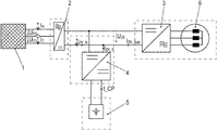
- FIG. 1 the system according to an example embodiment of the present invention including an energy accumulator 5 , which is connected to an intermediate circuit via a DC/DC converter 4 , is schematically illustrated.
- FIG. 2 shows a controller for operating the system, which controls the current withdrawn from the AC-voltage supply network to a setpoint value.
- FIG. 3 shows an example embodiment of DC/DC converter 4 .
- FIG. 4 shows an alternative control method for controlling the power absorbed from the AC-voltage supply network.
- a rectifier 2 is supplied at its AC-voltage side connection from a three-phase AC-voltage supply network 1 .
- a three network phase lines are provided, and current acquisitions (I_R, I_T) are provided in at least two of the three phase lines.
- the respective voltages existing between the phase lines are denoted by U_RS, U_ST and U_TR, respectively.
- the voltage U_ZK i.e. the intermediate-circuit voltage, is applied at the DC side connection of rectifier 2 .
- Current I_ZK_N emerges from the DC side connection of rectifier 2 .
- the DC side connection of a DC/DC converter 4 and the DC side connection of an inverter 3 supplying an electric motor 6 are switched in parallel and are able to be supplied from the DC side connection of rectifier 2 , the DC side connection of rectifier 2 particularly also being switched in parallel.
- Motor 6 may be arranged as a three-phase motor and connected at the AC-voltage side connection of inverter 3 .
- the housing of the DC/DC converter includes the current acquisition device adapted to acquire the current I_ZK_N emerging from the DC side connection of rectifier 2 .
- the current acquisition device adapted to acquire the currents flowing in the network phases (I_R, I_T) is situated inside the housing of DC/DC converter 4 .
- the rectifier and the inverter may be surrounded by another housing.
- This other housing may be set apart from the housing of the DC/DC converter.
- An energy accumulator 5 which has at least an accumulator cell, a battery cell, a capacitor and/or an ultracap cell, is connected at the other DC-voltage side connection of DC/DC converter 4 .
- the charging current I_CP of energy accumulator 5 emerging at this other DC-voltage side connection of DC/DC converter 4 is acquired using a current acquisition device, and the acquired value is forwarded to a signal electronics, which has a controller which controls the value to a setpoint value I_CP_setpoint by using the DC/DC converter as a final controlling element.
- the DC/DC converter has a dual configuration and is arranged as a cascading step-up/step-down converter which consequently has two parts that are switched in parallel, and the sum current I centrally acquired in DC/DC converter 4 is controlled to a setpoint value, in particular the setpoint value I_CP_setpoint, or to a setpoint value that is proportional thereto, in that the control signals of the switches of DC/DC converter 4 are generated accordingly, or in other words, in particular the pulse pattern, and in particular the pulse-width modulation ratio, is set accordingly.
- Each part of the dually implemented converter 4 has a half-bridge ( 31 and 32 , respectively) on the input side and a half-bridge ( 33 and 34 , respectively) on the output side, whose nodal point is connected with the aid of a respective inductivity (L 1 , L 2 ) in each case.
- Sum current I i.e. the sum of the current flowing through inductivity L 1 of the first part and the current flowing through inductivity L 2 of the second part, is acquired with the aid of a current-measuring device.
- This current-measuring device may be arranged as a toroidal core around which the respective feed line of the respective inductivity L 1 or L 2 is wound and around which an additional winding is implemented in order to acquire the induced voltage.
- Each one of the half-bridges ( 31 , 32 , 33 , 34 ) has two controllable semiconductor switches, which are connected in series, i.e. are connected at the nodal point.
- the dually cascading configuration of converter 4 results in low current rippling. It may particularly be reduced through an offset clocking of the two parts of converter 4 , in particular using control signals that are shifted by 180° relative to one another.
- a controller is provided, which is encompassed by the signal electronics of DC/DC converter 4 . As described earlier, the pulse pattern of the control signals of the semiconductor switches of converter 4 are set.
- Setpoint value I_CP_setpoint is determined as the controlled variable by the controller device shown in FIG. 2 and likewise encompassed by the signal electronics, in that current value I_ZK_N, acquired with the aid of the device for acquiring current I_ZK_N disposed in converter 4 , is used as the actual value, and the difference from a predefinable setpoint value I_ZK_N setpoint, in particular predefinable as a parameter, is determined. This difference is forwarded to the linear controller, i.e. proportional component K_P and integral component K_I, whose output signal, i.e. controlled variable, is used as setpoint value I_CP_setpoint.
- the linear controller i.e. proportional component K_P and integral component K_I
- setpoint value I_CP_setpoint is determined via a determination of the power withdrawn from the AC-voltage supply network.
- the acquired current that emerges at the DC-voltage side connection of rectifier 2 is multiplied by the voltage that is applied and acquired at the DC-voltage side connection of rectifier 2 .
- the difference between the power value P_network obtained in this manner and a predefinable setpoint value P_network_setpoint is forwarded to a linear controller, which once again has a proportional component K_P and an integral component K_I, in particular.
- power signal P_App via a precontrol path, i.e. in particular a path for a feedforward injection of a disturbance variable, which is determined by multiplying the voltage applied at the DC-voltage side connection of rectifier 2 and current I_ZK App supplied at the DC-voltage side connection of inverter 3 .
- Power signal P_App is multiplied by multiplication of voltage U_ZK actual, applied and acquired at the DC-current side connection of rectifier 2 , is multiplied by the current that emerges from the DC-current side connection of inverter 3 .
- the output signal of the controller enlarged by power signal P_App, is denoted by P_reg, and a power-loss signal P_V is summed up, which represents the power loss of the energy accumulator system.
- Power signal P_set obtained in this manner is divided by the voltage value U_accumulator applied and acquired at energy accumulator 5 , thereby determining setpoint value I_CP_setpoint.
- the controller controls sum current I acquired in DC/DC converter 4 to setpoint value I_CP_setpoint determined in this manner or to a setpoint value that is proportional thereto, in that the pulse pattern of the control signals of the semiconductor switches of DC/DC converter 4 are set accordingly.
- Power-loss signal P_V takes the no-load power of the system and the losses of DC/DC converter 4 into account in the process.
- the maximally permissible charging current I_CP_setpoint is restricted as a function of the amount of the exceedance, i.e. in particular as a function of the difference between the voltage applied at energy accumulator 5 and the critical voltage value, in particular restricted to a decreasing value especially as the amount of the difference increases, until zero has been reached, in particular when the cut-off voltage is reached.
- a superposed charge-state controller is provided in addition, which may have a considerably greater time constant than the cycle time of the application driven by the motor.
- the superposed charge-state controller controls the charge state to a medium charge state and does this such that during the generator-mode operation of the application, the maximum charge state of the energy accumulator is not exceeded, and during the motor-mode operation of the application, the setpoint value of power P_network_setpoint received from the AC-voltage supply network is not exceeded.
- a device adapted to detect a network failure whose output signal either induces a switch-off of inverter 3 or a supply of inverter 3 from energy accumulator 5 once a threshold value has been exceeded or has not been thereby achieving an uninterruptible power supply-functionality, i.e. in particular the functionality of a power supply without interruptions.
Landscapes
- Engineering & Computer Science (AREA)
- Power Engineering (AREA)
- Rectifiers (AREA)
- Inverter Devices (AREA)
Abstract
Description
- 1 AC-voltage supply network
- 2 rectifier
- 3 inverter for
electric motor 6 - 4 DC/DC converter for
energy accumulator 5 - 5 energy accumulator, in particular having an accumulator cell, a battery cell, capacitor, and/or an ultracap cell
- 6 electric motor
- 31 first half-bridge
- 32 second half-bridge
- 33 third half-bridge
- 34 fourth half-bridge
- I_R current acquisition in the first network phase
- I_S current acquisition in the second network phase
- I_T current acquisition in the third network phase
- U_RS first network voltage
- U_ST second network voltage
- U_TR third network voltage
- U_ZK_Ist actual value of the voltage applied at the DC-side connection of
rectifier 2 - I_ZK_N current emerging at the DC-side connection of
rectifier 2 - I_ZK App current emerging at the DC-side connection of
inverter 3 - I_ZK S current emerging at the DC-side connection of DC/DC converter 4
- U_ZK voltage applied at the DC-side connection of
rectifier 2 - I_ZK_N_Soll setpoint value for the current I_ZK_N emerging at the DC-side connection of the rectifier
- K_P proportional component
- K_I integral component
- I_S Soll setpoint value of the current component of the second network phase
- I_CP Soll setpoint value of the current emerging from
energy accumulator 5 - C1 first capacitor
- C2 second capacitor
- L1 first inductivity
- L2 second inductivity
- P_Netz_Soll setpoint value of the power absorbed from the AC-voltage supply network
- P_Netz power absorbed from the AC-voltage supply network
- P_APP power absorbed by the second motor, in particular
- P_V power loss
- U_Speicher voltage applied at the energy accumulator
- P_reg power to be ideally set
- P_set set value of the power
- I acquired compensating current
Claims (19)
Applications Claiming Priority (3)
| Application Number | Priority Date | Filing Date | Title |
|---|---|---|---|
| DE102016011423 | 2016-09-22 | ||
| DE102016011423.1 | 2016-09-22 | ||
| PCT/EP2017/025217 WO2018054543A1 (en) | 2016-09-22 | 2017-07-19 | System and method for operating a system |
Related Parent Applications (1)
| Application Number | Title | Priority Date | Filing Date |
|---|---|---|---|
| PCT/EP2017/025217 A-371-Of-International WO2018054543A1 (en) | 2016-09-22 | 2017-07-19 | System and method for operating a system |
Related Child Applications (1)
| Application Number | Title | Priority Date | Filing Date |
|---|---|---|---|
| US17/194,764 Continuation US11362596B2 (en) | 2016-09-22 | 2021-03-08 | System and method for operating a system |
Publications (2)
| Publication Number | Publication Date |
|---|---|
| US20190252992A1 US20190252992A1 (en) | 2019-08-15 |
| US10951126B2 true US10951126B2 (en) | 2021-03-16 |
Family
ID=59569271
Family Applications (2)
| Application Number | Title | Priority Date | Filing Date |
|---|---|---|---|
| US16/335,753 Active 2037-12-02 US10951126B2 (en) | 2016-09-22 | 2017-07-19 | System and method for operating a system |
| US17/194,764 Active US11362596B2 (en) | 2016-09-22 | 2021-03-08 | System and method for operating a system |
Family Applications After (1)
| Application Number | Title | Priority Date | Filing Date |
|---|---|---|---|
| US17/194,764 Active US11362596B2 (en) | 2016-09-22 | 2021-03-08 | System and method for operating a system |
Country Status (5)
| Country | Link |
|---|---|
| US (2) | US10951126B2 (en) |
| EP (1) | EP3516760A1 (en) |
| CN (1) | CN109874377B (en) |
| DE (1) | DE102017006819A1 (en) |
| WO (1) | WO2018054543A1 (en) |
Cited By (2)
| Publication number | Priority date | Publication date | Assignee | Title |
|---|---|---|---|---|
| US11362596B2 (en) * | 2016-09-22 | 2022-06-14 | Sew-Eurodrive Gmbh & Co. Kg | System and method for operating a system |
| US11750139B2 (en) | 2019-07-18 | 2023-09-05 | Sew-Eurodrive Gmbh & Co. Kg | Method and system for operating a system including an energy storage device and resistor |
Families Citing this family (6)
| Publication number | Priority date | Publication date | Assignee | Title |
|---|---|---|---|---|
| CN111211685B (en) * | 2018-11-21 | 2024-07-05 | 伊顿智能动力有限公司 | DC-DC converter, bidirectional DC-DC converter and uninterruptible power supply comprising same |
| CN111211688A (en) * | 2018-11-21 | 2020-05-29 | 伊顿智能动力有限公司 | DC-DC converter, bidirectional DC-DC converter and uninterruptible power supply comprising bidirectional DC-DC converter |
| CN111211686A (en) * | 2018-11-21 | 2020-05-29 | 伊顿智能动力有限公司 | DC-DC converter, bidirectional DC-DC converter and uninterruptible power supply comprising bidirectional DC-DC converter |
| DE102020003799A1 (en) * | 2019-07-18 | 2021-01-21 | Sew-Eurodrive Gmbh & Co Kg | Method for operating a system and system with a supply module, an inverter, an energy store and a power supply unit |
| DE102020004771A1 (en) * | 2019-09-06 | 2021-03-11 | Sew-Eurodrive Gmbh & Co Kg | Procedure for operating a system and system |
| EP3886305A1 (en) * | 2020-03-24 | 2021-09-29 | FRONIUS INTERNATIONAL GmbH | Method for operating an inverter and inverter for executing the method |
Citations (8)
| Publication number | Priority date | Publication date | Assignee | Title |
|---|---|---|---|---|
| JPH01308136A (en) | 1988-05-31 | 1989-12-12 | Toshiba Corp | Air-conditioner |
| JPH06225458A (en) | 1993-01-20 | 1994-08-12 | Hitachi Ltd | Power converter and controlling method |
| JP2003259566A (en) | 2002-03-05 | 2003-09-12 | Ntt Power & Building Facilities Inc | Ac power supply system |
| US20070137945A1 (en) * | 2004-03-18 | 2007-06-21 | Toshiba Elevator Kabushiki Kaisha | Elevator controller |
| US20080068870A1 (en) * | 2004-09-06 | 2008-03-20 | Honda Motor Co., Ltd. | Power Unit |
| US20140111005A1 (en) * | 2012-01-17 | 2014-04-24 | Huawei Technologies Co., Ltd. | Uninterruptible Power Supply and DC-DC Converter |
| DE102013006964A1 (en) | 2013-03-27 | 2014-10-02 | Sew-Eurodrive Gmbh & Co Kg | Device, in particular a machine or plant, and method for operating a device |
| US20160311332A1 (en) * | 2015-04-23 | 2016-10-27 | Hyundai Motor Company | Power supply apparatus for eco-friendly vehicle |
Family Cites Families (8)
| Publication number | Priority date | Publication date | Assignee | Title |
|---|---|---|---|---|
| JP2001226049A (en) | 2000-02-15 | 2001-08-21 | Mitsubishi Electric Corp | Control device for elevator |
| IL151275A0 (en) | 2000-03-31 | 2003-04-10 | Inventio Ag | Device and method for reducing the power of the supply connection in lift systems |
| EP1718081A1 (en) | 2004-02-19 | 2006-11-02 | Olympus Corporation | Imaging system and image processing program |
| KR101189428B1 (en) * | 2008-07-30 | 2012-10-10 | 도시바 미쓰비시덴키 산교시스템 가부시키가이샤 | Power conversion device |
| WO2012014292A1 (en) * | 2010-07-28 | 2012-02-02 | 三菱電機株式会社 | Chopper apparatus |
| US8884561B2 (en) * | 2010-09-06 | 2014-11-11 | Mitsubishi Electric Corporation | AC motor driving apparatus |
| DE102013009823A1 (en) * | 2013-06-11 | 2014-12-11 | Liebherr-Components Biberach Gmbh | Electric drive system and energy storage device therefor |
| CN109874377B (en) * | 2016-09-22 | 2022-10-28 | 索尤若驱动有限及两合公司 | System and method for operating a system |
-
2017
- 2017-07-19 CN CN201780057952.9A patent/CN109874377B/en active Active
- 2017-07-19 US US16/335,753 patent/US10951126B2/en active Active
- 2017-07-19 WO PCT/EP2017/025217 patent/WO2018054543A1/en unknown
- 2017-07-19 EP EP17749609.8A patent/EP3516760A1/en active Pending
- 2017-07-19 DE DE102017006819.4A patent/DE102017006819A1/en active Pending
-
2021
- 2021-03-08 US US17/194,764 patent/US11362596B2/en active Active
Patent Citations (8)
| Publication number | Priority date | Publication date | Assignee | Title |
|---|---|---|---|---|
| JPH01308136A (en) | 1988-05-31 | 1989-12-12 | Toshiba Corp | Air-conditioner |
| JPH06225458A (en) | 1993-01-20 | 1994-08-12 | Hitachi Ltd | Power converter and controlling method |
| JP2003259566A (en) | 2002-03-05 | 2003-09-12 | Ntt Power & Building Facilities Inc | Ac power supply system |
| US20070137945A1 (en) * | 2004-03-18 | 2007-06-21 | Toshiba Elevator Kabushiki Kaisha | Elevator controller |
| US20080068870A1 (en) * | 2004-09-06 | 2008-03-20 | Honda Motor Co., Ltd. | Power Unit |
| US20140111005A1 (en) * | 2012-01-17 | 2014-04-24 | Huawei Technologies Co., Ltd. | Uninterruptible Power Supply and DC-DC Converter |
| DE102013006964A1 (en) | 2013-03-27 | 2014-10-02 | Sew-Eurodrive Gmbh & Co Kg | Device, in particular a machine or plant, and method for operating a device |
| US20160311332A1 (en) * | 2015-04-23 | 2016-10-27 | Hyundai Motor Company | Power supply apparatus for eco-friendly vehicle |
Non-Patent Citations (4)
| Title |
|---|
| European Office Action mailed from the European Patent Office and issued to counterpart Application No. 17749609.8 dated May 4, 2020, 20 pages. |
| International Preliminary Report on Patentability issued in International Patent Application No. PCT/EP2017/025217, dated Apr. 4, 2109 (9 pages). |
| International Search Report dated Nov. 11, 2017, in International Application No. PCT/EP2017/025217 (English-language translation). |
| Regelkreis Die freie Ezyklopädie, https://de.wikipedia.org/w/index.php?title=Regelkreis&oldid=1570, accessed on Jun. 23, 2017. |
Cited By (2)
| Publication number | Priority date | Publication date | Assignee | Title |
|---|---|---|---|---|
| US11362596B2 (en) * | 2016-09-22 | 2022-06-14 | Sew-Eurodrive Gmbh & Co. Kg | System and method for operating a system |
| US11750139B2 (en) | 2019-07-18 | 2023-09-05 | Sew-Eurodrive Gmbh & Co. Kg | Method and system for operating a system including an energy storage device and resistor |
Also Published As
| Publication number | Publication date |
|---|---|
| US20210194379A1 (en) | 2021-06-24 |
| DE102017006819A1 (en) | 2018-03-22 |
| WO2018054543A1 (en) | 2018-03-29 |
| US20190252992A1 (en) | 2019-08-15 |
| CN109874377A (en) | 2019-06-11 |
| US11362596B2 (en) | 2022-06-14 |
| EP3516760A1 (en) | 2019-07-31 |
| CN109874377B (en) | 2022-10-28 |
Similar Documents
| Publication | Publication Date | Title |
|---|---|---|
| US11362596B2 (en) | System and method for operating a system | |
| US7106023B2 (en) | Motor driving apparatus | |
| US6335871B1 (en) | Motor operation controller and insulation type bidirectional DC voltage converter | |
| US5710699A (en) | Power electronic interface circuits for batteries and ultracapacitors in electric vehicles and battery storage systems | |
| US7612542B2 (en) | Power unit | |
| US8847555B2 (en) | Fast charging device for an electric vehicle | |
| EP3158631B1 (en) | Method and integrated motor drive power electronics system with improved efficiency | |
| US9444246B2 (en) | Power converter with switching element | |
| EP3339083B1 (en) | Power supply system for electric vehicle | |
| US10110000B2 (en) | Power management and distribution architecture for a space vehicle | |
| EP3531528B1 (en) | Power supply system and method for controlling same | |
| US9896048B2 (en) | Power supply unit for supplying power to an on-board electrical network of a vehicle | |
| US11050353B2 (en) | Power conversion device that generates switching signals | |
| KR20220103626A (en) | Inverter system, control method of inverter system and parallel connection inverter system | |
| CN111106601B (en) | Control of a DC voltage distribution system | |
| EP2437386A1 (en) | Stabilized high-voltage power supply | |
| JP2022069834A (en) | Power supply controller | |
| JPH11113191A (en) | Uninterruptible power-supply apparatus and its charging control method | |
| US11955904B2 (en) | DC/DC converter and power conversion device | |
| CN114270683A (en) | Regulating device for a DC voltage converter, DC voltage converter and method for regulating a DC voltage converter | |
| EP4254759A1 (en) | Dc/dc converter for battery chargers, and method of controlling such a dc/dc converter at very light load conditions | |
| CN111278676A (en) | Energy storage device and method for operating such an energy storage device | |
| JP7527138B2 (en) | Converter systems, industrial machinery | |
| KR101519758B1 (en) | A driving method of DC-DC convert and the apparatus thereof | |
| CA2792702A1 (en) | Stabilized high-voltage power supply |
Legal Events
| Date | Code | Title | Description |
|---|---|---|---|
| AS | Assignment |
Owner name: SEW-EURODRIVE GMBH & CO. KG, GERMANY Free format text: ASSIGNMENT OF ASSIGNORS INTEREST;ASSIGNORS:SCHMIDT, JOSEF;WEBER, JOCHEN;HAUCK, MATTHIAS;SIGNING DATES FROM 20181213 TO 20181217;REEL/FRAME:048669/0248 |
|
| FEPP | Fee payment procedure |
Free format text: ENTITY STATUS SET TO UNDISCOUNTED (ORIGINAL EVENT CODE: BIG.); ENTITY STATUS OF PATENT OWNER: LARGE ENTITY |
|
| STPP | Information on status: patent application and granting procedure in general |
Free format text: APPLICATION DISPATCHED FROM PREEXAM, NOT YET DOCKETED |
|
| STPP | Information on status: patent application and granting procedure in general |
Free format text: DOCKETED NEW CASE - READY FOR EXAMINATION |
|
| STPP | Information on status: patent application and granting procedure in general |
Free format text: RESPONSE TO NON-FINAL OFFICE ACTION ENTERED AND FORWARDED TO EXAMINER |
|
| STCF | Information on status: patent grant |
Free format text: PATENTED CASE |
|
| MAFP | Maintenance fee payment |
Free format text: PAYMENT OF MAINTENANCE FEE, 4TH YEAR, LARGE ENTITY (ORIGINAL EVENT CODE: M1551); ENTITY STATUS OF PATENT OWNER: LARGE ENTITY Year of fee payment: 4 |