US10951038B2 - Power supply device, power supply system, and method of controlling power supply - Google Patents
Power supply device, power supply system, and method of controlling power supply Download PDFInfo
- Publication number
- US10951038B2 US10951038B2 US15/022,140 US201415022140A US10951038B2 US 10951038 B2 US10951038 B2 US 10951038B2 US 201415022140 A US201415022140 A US 201415022140A US 10951038 B2 US10951038 B2 US 10951038B2
- Authority
- US
- United States
- Prior art keywords
- power
- conditioner
- power supply
- storage unit
- unit
- Prior art date
- Legal status (The legal status is an assumption and is not a legal conclusion. Google has not performed a legal analysis and makes no representation as to the accuracy of the status listed.)
- Active, expires
Links
Images


Classifications
-
- H02J3/383—
-
- H—ELECTRICITY
- H02—GENERATION; CONVERSION OR DISTRIBUTION OF ELECTRIC POWER
- H02J—CIRCUIT ARRANGEMENTS OR SYSTEMS FOR SUPPLYING OR DISTRIBUTING ELECTRIC POWER; SYSTEMS FOR STORING ELECTRIC ENERGY
- H02J7/00—Circuit arrangements for charging or depolarising batteries or for supplying loads from batteries
- H02J7/34—Parallel operation in networks using both storage and other DC sources, e.g. providing buffering
- H02J7/35—Parallel operation in networks using both storage and other DC sources, e.g. providing buffering with light sensitive cells
-
- H—ELECTRICITY
- H02—GENERATION; CONVERSION OR DISTRIBUTION OF ELECTRIC POWER
- H02J—CIRCUIT ARRANGEMENTS OR SYSTEMS FOR SUPPLYING OR DISTRIBUTING ELECTRIC POWER; SYSTEMS FOR STORING ELECTRIC ENERGY
- H02J3/00—Circuit arrangements for AC mains or AC distribution networks
- H02J3/12—Circuit arrangements for AC mains or AC distribution networks for adjusting voltage in AC networks by changing a characteristic of the network load
- H02J3/14—Circuit arrangements for AC mains or AC distribution networks for adjusting voltage in AC networks by changing a characteristic of the network load by switching loads on to, or off from, network, e.g. progressively balanced loading
-
- H—ELECTRICITY
- H02—GENERATION; CONVERSION OR DISTRIBUTION OF ELECTRIC POWER
- H02J—CIRCUIT ARRANGEMENTS OR SYSTEMS FOR SUPPLYING OR DISTRIBUTING ELECTRIC POWER; SYSTEMS FOR STORING ELECTRIC ENERGY
- H02J3/00—Circuit arrangements for AC mains or AC distribution networks
- H02J3/28—Arrangements for balancing of the load in a network by storage of energy
- H02J3/32—Arrangements for balancing of the load in a network by storage of energy using batteries with converting means
-
- H—ELECTRICITY
- H02—GENERATION; CONVERSION OR DISTRIBUTION OF ELECTRIC POWER
- H02J—CIRCUIT ARRANGEMENTS OR SYSTEMS FOR SUPPLYING OR DISTRIBUTING ELECTRIC POWER; SYSTEMS FOR STORING ELECTRIC ENERGY
- H02J3/00—Circuit arrangements for AC mains or AC distribution networks
- H02J3/38—Arrangements for parallely feeding a single network by two or more generators, converters or transformers
- H02J3/381—Dispersed generators
-
- H02J3/386—
-
- H—ELECTRICITY
- H02—GENERATION; CONVERSION OR DISTRIBUTION OF ELECTRIC POWER
- H02J—CIRCUIT ARRANGEMENTS OR SYSTEMS FOR SUPPLYING OR DISTRIBUTING ELECTRIC POWER; SYSTEMS FOR STORING ELECTRIC ENERGY
- H02J3/00—Circuit arrangements for AC mains or AC distribution networks
- H02J3/38—Arrangements for parallely feeding a single network by two or more generators, converters or transformers
- H02J3/46—Controlling of the sharing of output between the generators, converters, or transformers
-
- H—ELECTRICITY
- H02—GENERATION; CONVERSION OR DISTRIBUTION OF ELECTRIC POWER
- H02J—CIRCUIT ARRANGEMENTS OR SYSTEMS FOR SUPPLYING OR DISTRIBUTING ELECTRIC POWER; SYSTEMS FOR STORING ELECTRIC ENERGY
- H02J7/00—Circuit arrangements for charging or depolarising batteries or for supplying loads from batteries
- H02J7/0068—Battery or charger load switching, e.g. concurrent charging and load supply
-
- H02J7/865—
-
- H—ELECTRICITY
- H02—GENERATION; CONVERSION OR DISTRIBUTION OF ELECTRIC POWER
- H02J—CIRCUIT ARRANGEMENTS OR SYSTEMS FOR SUPPLYING OR DISTRIBUTING ELECTRIC POWER; SYSTEMS FOR STORING ELECTRIC ENERGY
- H02J9/00—Circuit arrangements for emergency or stand-by power supply, e.g. for emergency lighting
- H02J9/04—Circuit arrangements for emergency or stand-by power supply, e.g. for emergency lighting in which the distribution system is disconnected from the normal source and connected to a standby source
- H02J9/06—Circuit arrangements for emergency or stand-by power supply, e.g. for emergency lighting in which the distribution system is disconnected from the normal source and connected to a standby source with automatic change-over, e.g. UPS systems
- H02J9/061—Circuit arrangements for emergency or stand-by power supply, e.g. for emergency lighting in which the distribution system is disconnected from the normal source and connected to a standby source with automatic change-over, e.g. UPS systems for DC powered loads
-
- H—ELECTRICITY
- H02—GENERATION; CONVERSION OR DISTRIBUTION OF ELECTRIC POWER
- H02M—APPARATUS FOR CONVERSION BETWEEN AC AND AC, BETWEEN AC AND DC, OR BETWEEN DC AND DC, AND FOR USE WITH MAINS OR SIMILAR POWER SUPPLY SYSTEMS; CONVERSION OF DC OR AC INPUT POWER INTO SURGE OUTPUT POWER; CONTROL OR REGULATION THEREOF
- H02M3/00—Conversion of DC power input into DC power output
- H02M3/02—Conversion of DC power input into DC power output without intermediate conversion into AC
- H02M3/04—Conversion of DC power input into DC power output without intermediate conversion into AC by static converters
-
- H—ELECTRICITY
- H02—GENERATION; CONVERSION OR DISTRIBUTION OF ELECTRIC POWER
- H02M—APPARATUS FOR CONVERSION BETWEEN AC AND AC, BETWEEN AC AND DC, OR BETWEEN DC AND DC, AND FOR USE WITH MAINS OR SIMILAR POWER SUPPLY SYSTEMS; CONVERSION OF DC OR AC INPUT POWER INTO SURGE OUTPUT POWER; CONTROL OR REGULATION THEREOF
- H02M7/00—Conversion of AC power input into DC power output; Conversion of DC power input into AC power output
- H02M7/66—Conversion of AC power input into DC power output; Conversion of DC power input into AC power output with possibility of reversal
- H02M7/68—Conversion of AC power input into DC power output; Conversion of DC power input into AC power output with possibility of reversal by static converters
-
- H02J2101/24—
-
- H02J2105/12—
-
- Y—GENERAL TAGGING OF NEW TECHNOLOGICAL DEVELOPMENTS; GENERAL TAGGING OF CROSS-SECTIONAL TECHNOLOGIES SPANNING OVER SEVERAL SECTIONS OF THE IPC; TECHNICAL SUBJECTS COVERED BY FORMER USPC CROSS-REFERENCE ART COLLECTIONS [XRACs] AND DIGESTS
- Y02—TECHNOLOGIES OR APPLICATIONS FOR MITIGATION OR ADAPTATION AGAINST CLIMATE CHANGE
- Y02B—CLIMATE CHANGE MITIGATION TECHNOLOGIES RELATED TO BUILDINGS, e.g. HOUSING, HOUSE APPLIANCES OR RELATED END-USER APPLICATIONS
- Y02B70/00—Technologies for an efficient end-user side electric power management and consumption
- Y02B70/30—Systems integrating technologies related to power network operation and communication or information technologies for improving the carbon footprint of the management of residential or tertiary loads, i.e. smart grids as climate change mitigation technology in the buildings sector, including also the last stages of power distribution and the control, monitoring or operating management systems at local level
- Y02B70/3225—Demand response systems, e.g. load shedding, peak shaving
-
- Y—GENERAL TAGGING OF NEW TECHNOLOGICAL DEVELOPMENTS; GENERAL TAGGING OF CROSS-SECTIONAL TECHNOLOGIES SPANNING OVER SEVERAL SECTIONS OF THE IPC; TECHNICAL SUBJECTS COVERED BY FORMER USPC CROSS-REFERENCE ART COLLECTIONS [XRACs] AND DIGESTS
- Y02—TECHNOLOGIES OR APPLICATIONS FOR MITIGATION OR ADAPTATION AGAINST CLIMATE CHANGE
- Y02E—REDUCTION OF GREENHOUSE GAS [GHG] EMISSIONS, RELATED TO ENERGY GENERATION, TRANSMISSION OR DISTRIBUTION
- Y02E10/00—Energy generation through renewable energy sources
- Y02E10/50—Photovoltaic [PV] energy
- Y02E10/56—Power conversion systems, e.g. maximum power point trackers
-
- Y—GENERAL TAGGING OF NEW TECHNOLOGICAL DEVELOPMENTS; GENERAL TAGGING OF CROSS-SECTIONAL TECHNOLOGIES SPANNING OVER SEVERAL SECTIONS OF THE IPC; TECHNICAL SUBJECTS COVERED BY FORMER USPC CROSS-REFERENCE ART COLLECTIONS [XRACs] AND DIGESTS
- Y02—TECHNOLOGIES OR APPLICATIONS FOR MITIGATION OR ADAPTATION AGAINST CLIMATE CHANGE
- Y02E—REDUCTION OF GREENHOUSE GAS [GHG] EMISSIONS, RELATED TO ENERGY GENERATION, TRANSMISSION OR DISTRIBUTION
- Y02E10/00—Energy generation through renewable energy sources
- Y02E10/70—Wind energy
- Y02E10/76—Power conversion electric or electronic aspects
-
- Y—GENERAL TAGGING OF NEW TECHNOLOGICAL DEVELOPMENTS; GENERAL TAGGING OF CROSS-SECTIONAL TECHNOLOGIES SPANNING OVER SEVERAL SECTIONS OF THE IPC; TECHNICAL SUBJECTS COVERED BY FORMER USPC CROSS-REFERENCE ART COLLECTIONS [XRACs] AND DIGESTS
- Y02—TECHNOLOGIES OR APPLICATIONS FOR MITIGATION OR ADAPTATION AGAINST CLIMATE CHANGE
- Y02E—REDUCTION OF GREENHOUSE GAS [GHG] EMISSIONS, RELATED TO ENERGY GENERATION, TRANSMISSION OR DISTRIBUTION
- Y02E70/00—Other energy conversion or management systems reducing GHG emissions
- Y02E70/30—Systems combining energy storage with energy generation of non-fossil origin
-
- Y—GENERAL TAGGING OF NEW TECHNOLOGICAL DEVELOPMENTS; GENERAL TAGGING OF CROSS-SECTIONAL TECHNOLOGIES SPANNING OVER SEVERAL SECTIONS OF THE IPC; TECHNICAL SUBJECTS COVERED BY FORMER USPC CROSS-REFERENCE ART COLLECTIONS [XRACs] AND DIGESTS
- Y04—INFORMATION OR COMMUNICATION TECHNOLOGIES HAVING AN IMPACT ON OTHER TECHNOLOGY AREAS
- Y04S—SYSTEMS INTEGRATING TECHNOLOGIES RELATED TO POWER NETWORK OPERATION, COMMUNICATION OR INFORMATION TECHNOLOGIES FOR IMPROVING THE ELECTRICAL POWER GENERATION, TRANSMISSION, DISTRIBUTION, MANAGEMENT OR USAGE, i.e. SMART GRIDS
- Y04S20/00—Management or operation of end-user stationary applications or the last stages of power distribution; Controlling, monitoring or operating thereof
- Y04S20/20—End-user application control systems
- Y04S20/222—Demand response systems, e.g. load shedding, peak shaving
-
- Y—GENERAL TAGGING OF NEW TECHNOLOGICAL DEVELOPMENTS; GENERAL TAGGING OF CROSS-SECTIONAL TECHNOLOGIES SPANNING OVER SEVERAL SECTIONS OF THE IPC; TECHNICAL SUBJECTS COVERED BY FORMER USPC CROSS-REFERENCE ART COLLECTIONS [XRACs] AND DIGESTS
- Y04—INFORMATION OR COMMUNICATION TECHNOLOGIES HAVING AN IMPACT ON OTHER TECHNOLOGY AREAS
- Y04S—SYSTEMS INTEGRATING TECHNOLOGIES RELATED TO POWER NETWORK OPERATION, COMMUNICATION OR INFORMATION TECHNOLOGIES FOR IMPROVING THE ELECTRICAL POWER GENERATION, TRANSMISSION, DISTRIBUTION, MANAGEMENT OR USAGE, i.e. SMART GRIDS
- Y04S20/00—Management or operation of end-user stationary applications or the last stages of power distribution; Controlling, monitoring or operating thereof
- Y04S20/20—End-user application control systems
- Y04S20/248—UPS systems or standby or emergency generators
Definitions
- the present disclosure relates to a power supply device, a power supply system, and a method of controlling power supply, including a power generation unit such as solar photovoltaics and a power storage unit such as a battery, in addition to system power.
- a power generation unit such as solar photovoltaics
- a power storage unit such as a battery
- PV solar photovoltaic
- power generated by PV is supplied to devices used in a house in a case of a residual power purchase system, and excess power is sold to a power company.
- the mode of the PV is manually changed into an autonomous operation mode.
- the power generated by the PV is supplied to an emergency autonomous outlet only.
- electronic devices connected to the autonomous outlet can be used even in the power failure state. Types of electronic devices to be used at the time of power failure are set by the user in advance.
- Patent Literature 1 describes that power in a storage battery is output to a power line, and a power conditioner of a solar photovoltaic system is started based on the power at the time of power failure. Further, Patent Literature 1 describes that, when the storage battery is nearly fully charged, a power generation device is stopped in order to avoid excessive charging.
- PCS power conditioner system
- a power supply control device includes a control unit, and a power path that is connected to a primary external power system. If a connection state between the primary external power system and the power path is in a disconnected state, the control unit is configured to control power output of at least one power conditioner of at least one corresponding secondary external power generation unit, based on (a) an amount of power consumption of a specific load connected to the power supply control device through the power path, and (b) a power generation output of the secondary external power generation unit.
- a power supply control system in another embodiment, includes a power supply control device that includes a control unit, and a power path that is connected to a primary external power system, and a secondary external power generation system that is separate from the primary external power system and that is connected to the power supply control device.
- the secondary external power generation system includes at least one photovoltaic cell and a corresponding photovoltaic power conditioner connected to the photovoltaic cell. If the connection state information indicates that the primary external power system and the power path are in a disconnected state, said control unit is configured to control the power output of the photovoltaic power conditioner based on (a) an amount of power consumption of a specific load connected to the power supply control device through the power path, and (b) a power generation output of the secondary external power generation system.
- a method of controlling a power supply of a power supply device includes controlling, if a connection state between a primary external power system and a power path is in a disconnected state, power output of at least one power conditioner of at least one corresponding secondary external power generation unit based on (a) an amount of power consumption of a specific load connected to the power supply control device through the power path, and (b) a power generation output of the secondary external power generation unit.
- a power supply device including:
- a first path including a first power conditioner arranged between the power storage unit and the AC power path;
- a second path including the second power conditioner arranged between the power generation unit and the AC power path;
- control unit configured to control connection between the second path and the AC power path
- control unit controls ON/OFF of the second power conditioner according to a power generation output of the power generation unit and power consumption of the specific load when connection between the system power and the AC power path becomes disconnected.
- the present disclosure uses a commercially available PCS. Therefore, the present disclosure can build a power storage system in the form of extension with any already-installed solar photovoltaic system having any characteristics (photovoltaic panel+PCS). Therefore, currently holding assets can be used as they are, and the system can be realized at low cost. Note that the effects described here is not necessarily limited, and any effect described in the present disclosure may be exerted.
- FIG. 1 is a block diagram illustrating a system configuration of an embodiment of the present disclosure.
- FIG. 2 is a block diagram used for description of a power storage unit power conditioner and a PV power conditioner in an embodiment of the present disclosure.
- FIG. 3 is a block diagram used for description of selling of residual power in an embodiment of the present disclosure.
- FIG. 4 is a block diagram used for description of at the time of power failure in an embodiment of the present disclosure.
- FIG. 5 is a block diagram used for description of a system at the time of return in an embodiment of the present disclosure.
- FIG. 6 is a state transition diagram used for description of an operation in an embodiment of the present disclosure.
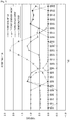
- FIG. 7 is a graph illustrating an example of power transition in an embodiment of the present disclosure.
- FIG. 8 is a graph illustrating another example of power transition in an embodiment of the present disclosure.
- FIG. 9 is a graph illustrating still another example of power transition in an embodiment of the present disclosure.
- FIG. 1 illustrates a system configuration of a power generation device according to an embodiment of the present disclosure.
- a parallel-off switch 52 is connected to an input side of system power
- a power storage device 4 including a power storage device power conditioner 81 and a storage battery 73
- a PV power generation system including solar power conditioners 6 and 16 and solar panels 5 and 15 are connected between a main AC power path and a specific load connected to an autonomous outlet 17 .
- the solar power conditioners 6 and 16 include a power conversion unit made of a DC-DC converter unit and a DC-AC inverter unit.
- the DC-DC converter unit raises an input DC voltage
- the DC-AC inverter unit converts a DC voltage from the DC-DC converter unit into AC power.
- the solar power conditioners 6 and 16 performs maximum power point tracking (MPPT).
- MPPT maximum power point tracking
- the parallel-off switch 53 is turned OFF and the power storage device power conditioner 81 is started, and power supply is performed to an AC power supply path. Further, the PV power generation system detects that there is power in the AC power supply path, starts the PCS of the PV power generation system, and starts an output.
- the PV power generation system is configured from two sets of the solar panels 5 and 15 as power generation units and the solar power conditioners 6 and 16 , which are arranged in parallel.
- the PV power generation system controls ON/OFF of outputs of the solar power conditioners 6 and 16 according to a remaining capacity of the storage battery 73 and the specific load. With the control, a risk of an increase in a voltage in the AC power supply path due to an excessive output of the PV power generation system is avoided, and the system can be safely and efficiently used.
- the power storage device 4 is stopped in a state where stored power necessary for restart of the solar power conditioners 6 and 16 is left.
- the fact that the generated power is returned is notified to the power storage device 4 side through a communication line.
- the power storage device 4 that has received the notification starts the solar power conditioners 6 and 16 using the power remained in the storage battery 73 , and outputs power supply to the AC power supply path. Therefore, the system can be automatically returned without human work.
- a general load 3 is connected to a power system 1 through a wattmeter 2 .
- a wattmeter 71 is connected from the wattmeter 2 through switches 51 and 52 .
- the switches 51 , 52 , and 56 are configured from manual switches.
- Switches 53 and 54 are configured from contacts of relay, for example, contacts of electromagnetic relay.
- Switches 58 , 59 , 62 , and 63 are also configured from contacts of relay.
- a wattmeter 72 is connected to the wattmeter 71 through the switch 53 . Further, the autonomous outlet 17 is connected to the wattmeter 72 through switches 54 and 55 .
- the autonomous outlet 17 is an emergency outlet that can take out power at the time of power failure. A plurality of autonomous outlets 17 may be provided as needed.
- the wattmeter 2 , and the wattmeters 71 , and 72 are inserted into an AC power path, and can measure an input of power from the power system 1 , and an output (reverse power flow) of power to the power system 1 , respectively.
- the wattmeters 71 and 72 are provided in the power storage device 4 .
- a path including the switch 56 that bypasses the wattmeters 71 and 72 is provided.
- AC power at an output side of the wattmeter 71 is supplied to the power storage device power conditioner (hereinafter, appropriately abbreviated as BATPCS) 81 . Further, AC power at an output side of the wattmeter 72 is supplied to BATPCS 81 .
- BATPCS power storage device power conditioner
- the storage battery 73 configured from a battery pack including a large number of lithium ion secondary batteries is provided.
- a battery management unit (BMU) 74 for controlling charging/discharging is connected to the storage battery 73 .
- the BMU 74 is connected to a DC-DC converter 83 in the BATPCS 81 through the switch 58 .
- the DC-DC converter 83 in the BATPCS 81 is connected to a bidirectional inverter 84 .
- the bidirectional inverter 84 is a bidirectional inverter having a function to convert a direct current into an alternating current and a function to convert an alternating current into a direct current. That is, the DC-DC converter 83 and the bidirectional inverter 84 configure a bidirectional power conditioner.
- the bidirectional inverter 84 is connected to the wattmeter 72 through the switch 59 .
- a control unit 82 for controlling internal circuits and switches is provided in the BATPCS 81 .
- An output of a counter electromotive force relay (RPR) 76 and an output of a ground fault overvoltage relay (OVGR) 77 are supplied to the control unit 82 .
- RPR counter electromotive force relay
- OVGR ground fault overvoltage relay
- the control unit 82 is connected to an energy management unit (EMU) 75 that is a higher controller.
- the EMU 75 controls the entire operation (mode switching) of the power storage device 4 .
- a start/return switch 64 is provided in connection with the EMU 75 . By manually pressing of the start/start/return switch 64 , the system can be returned from a system stop state to a system operating state.
- the BMU 74 , the control unit 82 , and the EMU 75 are configured from a microcomputer.
- An output of the wattmeter 72 is connected to the power storage device 4 .
- the switch 54 is turned ON.
- a plurality of power generation units for example, sets of the solar panels 5 and 15 and the solar power conditioners 6 and 16 are provided in parallel, separately from the power storage device 4 .
- the solar panels 5 and 15 are installed at positions irradiated with sunlight, and generate power by the sunlight.
- the generated power is output to each of the solar power conditioners (hereinafter, abbreviated as PVPCS) 6 and 16 through cables or the like.
- PVPCS solar power conditioners
- Three or more solar panels and PVPCSs may be provided.
- the PVPCSs 6 and 16 have a function to output maximum power, similarly to existing power conditioners, and do not have a power control function.
- Output power of the PVPCS 6 and output power of the PVPCS 16 are connected to between the wattmeter 72 and the switch 54 through the switches 62 and 63 , respectively.
- the switches 62 and 63 By control of the switches 62 and 63 , outputs of the PVPCSs 6 and 16 can be stopped.
- the switches 62 and 63 are turned OFF or the outputs of the PVPCSs 6 and 16 are stopped (hereinafter, both are collectively referred to as turning OFF outputs in the PVPCSs).
- ON/OFF of the outputs of the PVPCSs may be controlled by the switches 62 and 63 , and the outputs may be turned OFF by control of the PVPCSs 6 and 16 .
- Conditions of receiving irradiation of sunlight of the solar panels 5 and 15 may be the same or may be different.
- a pyranometer 8 and a thermometer 9 are provided. Data of the pyranometer 8 and the thermometer 9 is converted into digital data by a converter 10 , and is supplied to a data collecting device 7 . The collected data is transmitted from the data collecting device 7 to the EMU 75 of the power storage device 4 . Further, the collected data may be displayed by a display device 11 .
- a power generation device that uses natural energy such as wind power, or a power generation device that use fuel, other than the PV may be used as the power generation unit.
- the wattmeter 71 detects the system power, and transmits information thereof to the EMU 75 at the same time as (a-1).
- the control unit 82 of the BATPCS 81 is turned ON.
- the control unit 82 the BATPCS 81 and the PVPCSs 6 and 16 detect system connection, and the system operation becomes in a stand-by state.
- the BATPCS 81 and the PVPCSs 6 and 16 are started from the stand-by state within 300 seconds, for example (transferred to an operating state).
- the control unit 82 turns the switch 59 ON, so that an output of the storage battery 73 becomes available.
- the storage battery 73 is charged by residual power of the solar photovoltaics.
- the power is supplied from the storage battery 73 , and when the power is still insufficient, the power is supplied from the system.
- the EMU 75 collects information of the wattmeters 2 , 71 , and 72 , calculates an operation state of the entire power supply system, demand information, a power generation state, and the like based on the collected information, and automatically controls the power supply system to suppress power purchase from the system to the minimum.
- FIG. 3 is a connection configuration illustrating an operation of the control.
- the counter electromotive force relay 76 detects the reverse power flow and transmits a stop signal to the control unit 82 of the BATPCS 81 so that discharge power from the power storage device 4 do not reversely flow.
- the control unit 82 of the BATPCS 81 transmits a control signal, opens the switch 59 , and stops the output of the BATPCS 81 .
- connection is as illustrated in FIG. 4 .
- the BATPCS 81 performs an autonomous operation, and the PVPCSs 6 and 16 that has received an output thereof perform a system operation.
- a system operation output in synchronization with the output of the BATPCS 81 becomes available instead of an autonomous output, in which the output is restricted. Therefore, in the present embodiment, a total of 20 kw can be output where a maximum output of one PVPCS is 10 kw.
- the PVPCSs 6 and 16 are stopped, and only the power supply from the BATPCS 81 by the autonomous output is available.
- the EMU 75 stops discharging from the storage battery 73 because the EMU 75 monitors the remaining capacity of the storage battery 73 , and causes the mode to be a stand-by operation mode. In the stand-by operation, the BATPCS 81 automatically stops the discharging, transferred to the stand-by operation, and maintains a state in which the PVPCSs 6 and 16 can be restarted.
- the BATPCS 81 resumes the power supply, and restarts the PVPCSs 6 and 16 . Determination may be made by a combination of the both conditions. For example, when the PV panel voltage is a voltage equal to or more than a voltage that can start the PVPCSs 6 and 16 in (8 o'clock to 19 o'clock), the BATPCS 81 restarts the PVPCSs 6 and 16 . Therefore, charging of the storage battery 73 is started.
- the power supply to the load is resumed by a flow of normal power at the time of power failure, through the autonomous outlet 17 .
- the storage battery 73 is charged with the residual power.
- Control of when system returning performed is illustrated in FIG. 5 .
- the PVPCSs 6 and 16 are started, and starts a system operation.
- the storage battery 73 is charged by the solar photovoltaic power, and when the storage battery 73 is charged to a set threshold (about 15%), the switch 54 is turned ON, and power supply is resumed from the BATPCS 81 and the PVPCSs 6 and 16 to the load connected to the autonomous outlet 17 , and the system is transferred to a normal operation.
- the EMU 75 detects the power recovery according to the information from the wattmeter 71 .
- the BATPCS 81 is transferred from the autonomous output to a stop state.
- the above-described control of an embodiment of the present disclosure will be further described with reference to the state transition diagram of FIG. 6 .
- the states are roughly classified into a power supply interruption state ST 0 , a normal operation state ST 1 , and a power failure operation state ST 10 .
- the power failure operation state ST 10 includes a power supply mode ST 100 , a PV output restriction mode ST 101 , and a PV charge stand-by mode ST 20 .
- step S 0 when the start/return switch 64 is turned ON, the state is transferred into any of the normal operation state ST 1 , the power failure operation state ST 10 , and the PV charge stand-by mode ST 20 .
- step S 1 when it is determined that there is system power, the processing is moved onto the normal operation state ST 1 .
- step S 2 when it is detected that there is no system power (power failure), the processing is moved onto the power failure operation state ST 10 .
- step S 3 when the power failure is detected, and it is determined that the remaining capacity of the battery is less than a stand-by condition, the processing is moved onto the PV charge stand-by mode ST 20 .
- the PV output restriction mode ST 101 is a mode to selectively operate one of the two PVs. That is, one of the PVPCSs connected to the solar panels, which is more likely to be able to secure larger generated power, is selectively operated (a PVPCS 1 operation mode ST 102 or a PVPCS 2 operation mode ST 103 ).
- the PVPCS 6 in FIG. 1 is called PVPCS 1 in FIG. 6
- the PVPCS 16 is called PVPCS 2 .
- step S 12 When determination of step S 12 is established in the PV output restriction mode ST 101 (the PVPCS 1 operation mode ST 102 or the PVPCS 2 operation mode ST 103 ), the mode is moved onto a PV output full mode ST 104 that makes a PV output full.
- the PV output full mode is a mode to turn all of the PVPCSs (the PVPCS 1 and the PVPCS 2 ) ON.
- Step S 12 is a case in which it can be expected that the power does not exceed inputtable power of the bidirectional inverter 84 even if all of the PVPCSs are operated because the generated power of the PVs becomes small or due to an increase in load power.
- Step S 13 is a case in which it can be expected that the power exceeds the inputtable power of the bidirectional inverter 84 when power conditioners of all of the PVPCSs are operated because the power generation amounts of the PVs is increased or the load power is decreased.
- the prediction in step S 12 or S 13 is performed by comparison of each of current power generation amounts of the PVs, the load power, and the inputtable power of the bidirectional inverter 84 .
- step S 14 When determination of step S 14 is established in the PV output restriction mode ST 101 , the processing is transferred to a charge stop mode ST 105 . In the charge stop mode ST 105 , all of the PCSs are turned OFF. In step S 14 , it is determined that it can be expected that the power exceeds the inputtable power of the bidirectional inverter 84 of the BATPCS 81 even if the operation is performed by one PVPCS, due to an increase in the power generation amount of the PV or a decrease in the load power.
- step S 15 When determination of step S 15 is established in the PV output restriction mode ST 101 , the processing is moved onto a PV stop mode ST 106 .
- the PV stop mode ST 106 In the PV stop mode ST 106 , all of the PVPCSs 6 and 16 are turned OFF.
- step S 15 it is determined that a maximum cell voltage in the storage battery 73 has reached a charge stop voltage. Note that, when it is determined that the maximum cell voltage has reached the charge stop voltage in the PV output full mode ST 104 (step S 16 ), the processing is also moved onto the PV stop mode ST 106 .
- step S 17 in the PV stop mode ST 106 the processing is moved onto the PV output restriction mode ST 101 .
- step S 18 in the charge stop mode ST 105 the processing is moved onto the PV output restriction mode ST 101 .
- step S 21 in the power failure operation mode ST 10 When it is determined that the battery remaining capacity is less than the stand-by condition (e.g., 10% of the remaining capacity) in step S 21 in the power failure operation mode ST 10 , the processing is transferred to a PV startup/preliminary charge mode ST 201 in the PV charge stand-by mode ST 20 .
- the switch 54 In the PV charge stand-by mode ST 20 , the switch 54 is turned OFF, and the power supply to the autonomous outlet 17 is stopped. This is because consumption of the battery power for startup of the PVPCS due to a load is prevented.
- PV startup/preliminary charge mode ST 201 is a mode to selectively operate one of the two PVs. That is, one of the PVPCS 1 and the PVPCS 2 connected to the solar panels, which is more likely to be able to secure larger generated power, is selectively operates (a PVPCS 1 operation mode ST 202 or a PVPCS 2 operation mode ST 203 ).
- the PVPCS 1 operation mode ST 202 the PVPCS 1 is turned ON, and the bidirectional inverter 84 performs an autonomous operation.
- step S 22 When determination of step S 22 is established in the PV startup/preliminary charge mode ST 201 (the PVPCS 1 operation mode ST 202 or the PVPCS 2 operation mode ST 203 ), the processing is transferred to a bidirectional inverter (INV) output stop mode ST 204 .
- the bidirectional inverter (INV) output stop mode 204 is a mode in which the bidirectional inverter is stopped, and the PVPCS are turned OFF.
- step S 22 it is determined that the generated power is smaller than a specified value.
- step S 23 processing of confirming power generation states of the PVPCS 1 and the PVPCS 2 in every predetermined time (e.g., in every ten minutes) in a time period of daytime (e.g., 8 o'clock to 19 o'clock).
- step S 24 in the bidirectional inverter (INV) output stop mode ST 204 the state becomes the power supply interruption state ST 0 .
- the processing is moved onto the PV output restriction mode ST 101 of the power supply mode ST 100 .
- FIG. 7 is an example of the power transition in a fine day
- FIG. 8 is an example of the power transition in a cloudy weather
- FIG. 9 is an example of the power transition of when power failure occurs in a fine day.
- a minimum value of the power generation amount is 0.
- the negative side of the power indicates a charged state of the power storage device.
- the PV power generation amount has a peak at 12 o'clock to 13 o'clock. Little power generation amount is caused in the nighttime.
- the power consumption has peaks in the morning, afternoon, and evening to night, respectively.
- the power is changed as follows in the fine day illustrated in FIG. 7 .
- Nighttime The system power is used.
- the power storage device is charged.
- Morning Mainly, the PV power is used, and partially, the system power is used.
- the PV power reversely flows to the system.
- the PV power is used.
- the power storage device is charged by the PV power.
- the power is changed as follows in the cloudy weather illustrated in FIG. 8 .
- Nighttime The system power is used.
- the power storage device is charged.
- Morning Mainly the PV power is used, and partially, the system power is used. The PV power reversely flows to the system.
- Daytime The PV power is used. Partially, the system power is used. The power storage device is charged.
- the power is changed as follows at the time of power failure illustrated in FIG. 9 .
- the PV power is used. In a rainy weather, the residual power of the power storage device is used. When the remaining capacity is decreased, the output of the power storage device is paused.
- the present disclosure uses a commercially available PCS, the present disclosure can build a power storage system in the form of extension with any already-installed solar photovoltaic system having any characteristics (panel+PCS). Therefore, currently holding assets can be used as they are, and the system can be realized at low cost.
- a plurality of solar photovoltaic systems is connected in parallel, and the switches are connected in the lines from the solar photovoltaic systems to the load. Therefore, an increase in the voltage of the AC power system (load line) due to excessive power supply can be prevented.
- the total output of the PVPCS panels is the PCS output or more. Therefore, the power generation amount in the morning and in the evening can be made higher, and an operating ratio of one day can be increased.
- This configuration is installed in a duplex manner, so that the operation of the reverse flow power in the normal power can be stabilized, and the stability of the PV power generation/charge of the storage battery at the time of power failure can be stabilized. Moreover, reduction of unnecessary power can be realized while the PV power generation is linked with the power supply to the load power where the storage battery is nearly fully charged.
- a power supply control device comprising:
- control unit is configured to control power output of at least one power conditioner of at least one corresponding secondary external power generation unit, based on
- control unit configured to control a number of the power conditioners to be turned on.
- control unit is configured to increase the number of the power conditioners to be turned on when it is estimated that inputtable power of a power conditioner connected to the power storage unit will not be exceeded.
- control unit is configured to decrease the number of the power conditioners to be turned on when it is estimated that inputtable power of a power conditioner connected to the power storage unit will be exceeded.
- the power conditioner of the secondary external power generation unit and a power conditioner connected to the power storage unit are turned off when generated power of the power conditioner of the secondary external power generation unit is less than a predetermined value
- the power storage unit is charged when the generated power of the power conditioner of the secondary external power generation unit is larger than the predetermined value.
- a power conditioner connected to the power storage unit is a bidirectional power conditioner including a DC-DC converter and a bidirectional inverter.
- a power supply control system comprising:
- a power supply control device that includes a control unit, and a power path that is connected to a primary external power system
- the control unit is configured to control the power output of the photovoltaic power conditioner based on
- control unit is configured to increase the number of the power conditioners to be turned on when it is estimated that inputtable power of a power conditioner connected to the power storage unit will not be exceeded.
- the power conditioner of the secondary external power generation unit and a power conditioner connected to the power storage unit are turned off when generated power of the power conditioner of the secondary external power generation unit is less than a predetermined value
- the power storage unit is charged when the generated power of the power conditioner of the secondary external power generation unit is larger than the predetermined value.
- a power conditioner connected to the power storage unit is a bidirectional power conditioner including a DC-DC converter and a bidirectional inverter.
- a method of controlling a power supply of a power supply device comprising:
- the power conditioner of the secondary external power generation unit and a power conditioner connected to the power storage unit are turned off when generated power of the power conditioner of the secondary external power generation unit is less than a predetermined value
- the power storage unit is charged when the generated power of the power conditioner of the secondary external power generation unit is larger than the predetermined value.
- the power conditioner connected to the power storage unit is a bidirectional power conditioner including a DC-DC converter and a bidirectional inverter.
- a power supply device including:
- a first path including a first power conditioner arranged between the power storage unit and the AC power path;
- a second path including the second power conditioner arranged between the power generation unit and the AC power path;
- control unit configured to control connection between the second path and the AC power path
- control unit controls ON/OFF of the second power conditioner according to a power generation output of the power generation unit and power consumption of the specific load when connection between the system power and the AC power path becomes disconnected.
- the power supply device wherein a plurality of sets of the power generation units and the second power conditioners is connected in parallel, and the plurality of second power conditioners is mutually controlled in synchronization with the system power or an output of the power storage unit.
- control unit decreases the number of the second power conditioners to be turned ON when the inputtable power of the first power conditioner being not exceeded is expectable.
- the power supply device according to any of (1′) to (4′), wherein a remaining capacity of the power storage unit is a predetermined value or less, supply of power to the specific load is stopped, and the power supply device is transferred to a stand-by mode in which the second power conditioner performs an autonomous operation.
- the power supply device according to any of (1′) to (6′), wherein the control unit controls the connection between the system power and the AC power path.
- the power storage unit is charged when the generated power of the second power conditioner is larger than the predetermined value, and whether the remaining capacity of the power storage unit is larger than a predetermined value is determined, and the supply of power to the specific load is resumed when the remaining capacity of the power storage unit is larger than the predetermined value.
- the power supply device according to any of (1′) to (8′), wherein, in the stand-by mode, the power is interrupted when the power of the power storage unit runs out, or a minimum cell voltage of the power storage unit is a discharge stop voltage or less.
- the power supply device according to any of (1′) to (9′), wherein the first power conditioner is a bidirectional power conditioner.
- the power supply device according to any of (1′) to (10′), wherein the power generation unit is a power generation device using natural energy.
- the power supply device according to any of (1′) to (11′), wherein the specific load is a load connected to an autonomous outlet.
- a power supply system including:
- system power configured to supply power to a general load system
- a first path including a first power conditioner arranged between the power storage unit and the AC power path;
- a second path including the second power conditioner arranged between the power generation unit and the AC power path;
- control unit configured to control connection between the second path and the AC power path
- control unit controls ON/OFF of the second power conditioner according to a power generation output of the power generation unit and power consumption of the specific load when the connection between the system power and the AC power path becomes disconnected.
- a method of controlling power supply including:
- system power configured to supply power to a general load system
- a first path including a first power conditioner arranged between the power storage unit and the AC power path;
- a second path including the second power conditioner arranged between the power generation unit and the AC power path;
- control unit configured to control connection between the second path and the AC power path
- control unit controls ON/OFF of the second power conditioner according to a power generation output of the power generation unit and power consumption of the specific load when the connection between the system power and the AC power path becomes disconnected.
- the present disclosure is not limited to the above-described embodiments, and various modifications based on the technical idea of the present disclosure can be made.
- the configurations, methods, processes, shapes, materials, and numerical values described in the embodiments are merely examples, and different configurations, methods, processes, shapes, materials, and numerical values from the examples may be used as needed.
- one embodiment described above employs a configuration of connecting a plurality of power generation units in parallel.
- a system may be configured from a single power generation unit.
- connection/disconnection may be switched not only by the switches, but also by ON/OFF of power supplies of connected devices.
- an electric vehicle (EV) may be connected in place of the storage battery 73 .
- EV electric vehicle
Landscapes
- Engineering & Computer Science (AREA)
- Power Engineering (AREA)
- Business, Economics & Management (AREA)
- Emergency Management (AREA)
- Charge And Discharge Circuits For Batteries Or The Like (AREA)
- Supply And Distribution Of Alternating Current (AREA)
Abstract
Description
Claims (18)
Applications Claiming Priority (4)
| Application Number | Priority Date | Filing Date | Title |
|---|---|---|---|
| JP2013272777A JP6160481B2 (en) | 2013-12-27 | 2013-12-27 | Power supply device, power supply system, and power supply control method |
| JPJP2013-272777 | 2013-12-27 | ||
| JP2013-272777 | 2013-12-27 | ||
| PCT/JP2014/006240 WO2015098034A1 (en) | 2013-12-27 | 2014-12-16 | Power supply device, power supply system, and method of controlling power supply |
Publications (2)
| Publication Number | Publication Date |
|---|---|
| US20160226255A1 US20160226255A1 (en) | 2016-08-04 |
| US10951038B2 true US10951038B2 (en) | 2021-03-16 |
Family
ID=52395103
Family Applications (1)
| Application Number | Title | Priority Date | Filing Date |
|---|---|---|---|
| US15/022,140 Active 2036-10-08 US10951038B2 (en) | 2013-12-27 | 2014-12-16 | Power supply device, power supply system, and method of controlling power supply |
Country Status (5)
| Country | Link |
|---|---|
| US (1) | US10951038B2 (en) |
| EP (1) | EP3087655B1 (en) |
| JP (1) | JP6160481B2 (en) |
| CA (1) | CA2933447A1 (en) |
| WO (1) | WO2015098034A1 (en) |
Cited By (1)
| Publication number | Priority date | Publication date | Assignee | Title |
|---|---|---|---|---|
| US11539212B2 (en) * | 2018-02-05 | 2022-12-27 | Huawei Digital Power Technologies Co., Ltd. | Photovoltaic power generation system and photovoltaic power transmission method |
Families Citing this family (15)
| Publication number | Priority date | Publication date | Assignee | Title |
|---|---|---|---|---|
| WO2016121402A1 (en) * | 2015-01-28 | 2016-08-04 | 京セラ株式会社 | Electric power control device, electric power control system, and electric power control method |
| CN105207263B (en) * | 2015-09-30 | 2018-01-19 | 四川海天环保能源有限公司 | The photovoltaic generating system and grid-connected control method of garbage incinerating power plant |
| CN105668919A (en) * | 2016-01-11 | 2016-06-15 | 江苏师范大学 | A green purification and reuse system for high-rise building domestic sewage and its control method |
| JP6505258B2 (en) * | 2016-01-20 | 2019-04-24 | 三菱電機株式会社 | Power conditioner |
| US11139654B2 (en) | 2016-02-10 | 2021-10-05 | Eguana Technologies | Output control and compensation for AC coupled systems |
| JP6610419B2 (en) * | 2016-05-12 | 2019-11-27 | サンケン電気株式会社 | Power storage system, control program, and recording medium |
| US10628897B2 (en) | 2017-01-10 | 2020-04-21 | Solaredge Technologies Ltd. | System and method for controlling a stand-alone direct current power system |
| WO2018161326A1 (en) * | 2017-03-09 | 2018-09-13 | 邹霞 | Power supply device for positioning system of long-distance vehicle, and power supply method for same |
| CN107979157A (en) * | 2017-11-22 | 2018-05-01 | 中国电子科技集团公司第四十八研究所 | A kind of energy supplyystem and control method of advection layer solar dirigible |
| JP7261977B2 (en) * | 2018-11-30 | 2023-04-21 | パナソニックIpマネジメント株式会社 | Control system, power system, control method and program |
| US12136843B2 (en) * | 2019-09-19 | 2024-11-05 | MicroNOC Inc. | Elevator emergency power systems and methods |
| CN111327272B (en) * | 2020-03-10 | 2021-04-06 | 三河益生电子科技开发有限公司 | A solar photovoltaic power monitoring system |
| US11695297B2 (en) * | 2020-05-20 | 2023-07-04 | Sunpower Corporation | Photovoltaic disconnect device for storage integration |
| JP7498145B2 (en) * | 2021-04-26 | 2024-06-11 | 京セラ株式会社 | Power Conversion Systems |
| KR20230052034A (en) * | 2021-10-12 | 2023-04-19 | 엘지전자 주식회사 | Energy Storage System |
Citations (28)
| Publication number | Priority date | Publication date | Assignee | Title |
|---|---|---|---|---|
| US3419779A (en) * | 1965-08-09 | 1968-12-31 | Westinghouse Electric Corp | System for removing a bad battery from charging circuit |
| JP2002199589A (en) | 2000-12-27 | 2002-07-12 | Matsushita Electric Works Ltd | Photovoltaic power generator system |
| US20050006958A1 (en) * | 2003-07-11 | 2005-01-13 | Dubovsky Stephen M. | Grid-connected power systems having back-up power sources and methods of providing back-up power in grid-connected power systems |
| US20070063671A1 (en) * | 2005-09-16 | 2007-03-22 | Simpson Russell L | Apparatus and switching method for improving cycle-life and capacity of a battery pack |
| US20080203820A1 (en) * | 2007-02-27 | 2008-08-28 | Sma Technologie Ag | Backup power system |
| US20100000804A1 (en) * | 2008-07-02 | 2010-01-07 | Ming-Hsiang Yeh | Solar vehicle |
| US20100174418A1 (en) * | 2009-01-02 | 2010-07-08 | International Business Machines Corporation | Distributed grid-interactive photovoltaic-based power dispatching |
| US20110273019A1 (en) * | 2010-03-04 | 2011-11-10 | De Caires Damian | Solar panel power management system and method |
| EP2393153A1 (en) | 2010-06-07 | 2011-12-07 | Samsung SDI Co., Ltd. | Energy storage system |
| JP3172855U (en) | 2011-10-25 | 2012-01-12 | 株式会社ホットプラン | Power supply device and power supply system using the same |
| EP2451042A1 (en) | 2009-06-30 | 2012-05-09 | Panasonic Corporation | Power distribution system |
| US20120306271A1 (en) * | 2011-06-03 | 2012-12-06 | Renesas Electronics Corporation | Storage battery system |
| US8461807B2 (en) * | 2009-03-27 | 2013-06-11 | Tdk-Lambda Corporation | Battery protection circuit, method for protecting battery, power supply device and program |
| EP2602903A1 (en) | 2011-12-09 | 2013-06-12 | Delta Electronics, Inc. | Power management apparatus and method of operating the same |
| JP2013176282A (en) | 2012-01-27 | 2013-09-05 | Mitsubishi Heavy Ind Ltd | Power generation system provided with power generation facilities and power storage device, control method thereof and program |
| JP2013183613A (en) | 2012-03-05 | 2013-09-12 | Sanyo Electric Co Ltd | Controller, converter, control method, and power distribution system |
| JP2013226027A (en) | 2012-03-23 | 2013-10-31 | Sharp Corp | Power conditioner for storage battery and power supply system |
| WO2013179357A1 (en) | 2012-05-31 | 2013-12-05 | 三洋電機株式会社 | Controller and power distribution system |
| US20140062192A1 (en) * | 2012-09-05 | 2014-03-06 | Axion Power International, Inc. | Grid interactive double conversion inverter |
| US20140181541A1 (en) * | 2012-12-21 | 2014-06-26 | Hitachi, Ltd. | Information equipment and battery charge circuit |
| US20140285010A1 (en) * | 2011-05-24 | 2014-09-25 | D. Kevin CAMERON | System and method for integrating and managing demand/response between alternative energy sources, grid power, and loads |
| US20140361624A1 (en) * | 2013-06-10 | 2014-12-11 | Active Power, Inc. | Apparatus and methods for control of load power quality in uninterruptible power systems |
| US20150295413A1 (en) * | 2011-05-08 | 2015-10-15 | Paul Wilkinson Dent | Remotely controlled photovoltaic string combiner |
| US20150318700A1 (en) * | 2012-11-26 | 2015-11-05 | Panasonic Intellectual Property Management Co., Ltd. | Power supply system, power conversion apparatus, and measurement point switching apparatus |
| US20160016483A1 (en) * | 2013-04-03 | 2016-01-21 | Autonetworks Technologies, Ltd. | Control apparatus, power supply control apparatus, charge control method, charge control apparatus, and power supply apparatus for vehicles |
| US20160202682A1 (en) * | 2013-08-29 | 2016-07-14 | Kyocera Corporation | Energy management device, energy management method, and energy management system |
| US20160211670A1 (en) * | 2013-07-29 | 2016-07-21 | Kyocera Corporation | Power controller, power control method, and power control system |
| US9711967B1 (en) * | 2012-11-06 | 2017-07-18 | Reliance Conrtols Corporation | Off grid backup inverter automatic transfer switch |
-
2013
- 2013-12-27 JP JP2013272777A patent/JP6160481B2/en active Active
-
2014
- 2014-12-16 CA CA2933447A patent/CA2933447A1/en not_active Abandoned
- 2014-12-16 US US15/022,140 patent/US10951038B2/en active Active
- 2014-12-16 WO PCT/JP2014/006240 patent/WO2015098034A1/en not_active Ceased
- 2014-12-16 EP EP14830416.5A patent/EP3087655B1/en active Active
Patent Citations (31)
| Publication number | Priority date | Publication date | Assignee | Title |
|---|---|---|---|---|
| US3419779A (en) * | 1965-08-09 | 1968-12-31 | Westinghouse Electric Corp | System for removing a bad battery from charging circuit |
| JP2002199589A (en) | 2000-12-27 | 2002-07-12 | Matsushita Electric Works Ltd | Photovoltaic power generator system |
| US20050006958A1 (en) * | 2003-07-11 | 2005-01-13 | Dubovsky Stephen M. | Grid-connected power systems having back-up power sources and methods of providing back-up power in grid-connected power systems |
| US20070063671A1 (en) * | 2005-09-16 | 2007-03-22 | Simpson Russell L | Apparatus and switching method for improving cycle-life and capacity of a battery pack |
| US20080203820A1 (en) * | 2007-02-27 | 2008-08-28 | Sma Technologie Ag | Backup power system |
| US20100000804A1 (en) * | 2008-07-02 | 2010-01-07 | Ming-Hsiang Yeh | Solar vehicle |
| US20100174418A1 (en) * | 2009-01-02 | 2010-07-08 | International Business Machines Corporation | Distributed grid-interactive photovoltaic-based power dispatching |
| US8461807B2 (en) * | 2009-03-27 | 2013-06-11 | Tdk-Lambda Corporation | Battery protection circuit, method for protecting battery, power supply device and program |
| US20120299383A1 (en) * | 2009-06-30 | 2012-11-29 | Panasonic Electric Works Co., Ltd | Power distribution system |
| EP2451042A1 (en) | 2009-06-30 | 2012-05-09 | Panasonic Corporation | Power distribution system |
| US20110273019A1 (en) * | 2010-03-04 | 2011-11-10 | De Caires Damian | Solar panel power management system and method |
| EP2393153A1 (en) | 2010-06-07 | 2011-12-07 | Samsung SDI Co., Ltd. | Energy storage system |
| US20150295413A1 (en) * | 2011-05-08 | 2015-10-15 | Paul Wilkinson Dent | Remotely controlled photovoltaic string combiner |
| US20140285010A1 (en) * | 2011-05-24 | 2014-09-25 | D. Kevin CAMERON | System and method for integrating and managing demand/response between alternative energy sources, grid power, and loads |
| US20120306271A1 (en) * | 2011-06-03 | 2012-12-06 | Renesas Electronics Corporation | Storage battery system |
| JP3172855U (en) | 2011-10-25 | 2012-01-12 | 株式会社ホットプラン | Power supply device and power supply system using the same |
| EP2602903A1 (en) | 2011-12-09 | 2013-06-12 | Delta Electronics, Inc. | Power management apparatus and method of operating the same |
| US20130147274A1 (en) * | 2011-12-09 | 2013-06-13 | Chen-Wei KU | Power management apparatus and method of operating the same |
| JP2013176282A (en) | 2012-01-27 | 2013-09-05 | Mitsubishi Heavy Ind Ltd | Power generation system provided with power generation facilities and power storage device, control method thereof and program |
| JP2013183613A (en) | 2012-03-05 | 2013-09-12 | Sanyo Electric Co Ltd | Controller, converter, control method, and power distribution system |
| US20150028677A1 (en) * | 2012-03-05 | 2015-01-29 | Sanyo Electric Co., Ltd. | Control device, conversion device, control method, and electricity distribution system |
| JP2013226027A (en) | 2012-03-23 | 2013-10-31 | Sharp Corp | Power conditioner for storage battery and power supply system |
| WO2013179357A1 (en) | 2012-05-31 | 2013-12-05 | 三洋電機株式会社 | Controller and power distribution system |
| US20140062192A1 (en) * | 2012-09-05 | 2014-03-06 | Axion Power International, Inc. | Grid interactive double conversion inverter |
| US9711967B1 (en) * | 2012-11-06 | 2017-07-18 | Reliance Conrtols Corporation | Off grid backup inverter automatic transfer switch |
| US20150318700A1 (en) * | 2012-11-26 | 2015-11-05 | Panasonic Intellectual Property Management Co., Ltd. | Power supply system, power conversion apparatus, and measurement point switching apparatus |
| US20140181541A1 (en) * | 2012-12-21 | 2014-06-26 | Hitachi, Ltd. | Information equipment and battery charge circuit |
| US20160016483A1 (en) * | 2013-04-03 | 2016-01-21 | Autonetworks Technologies, Ltd. | Control apparatus, power supply control apparatus, charge control method, charge control apparatus, and power supply apparatus for vehicles |
| US20140361624A1 (en) * | 2013-06-10 | 2014-12-11 | Active Power, Inc. | Apparatus and methods for control of load power quality in uninterruptible power systems |
| US20160211670A1 (en) * | 2013-07-29 | 2016-07-21 | Kyocera Corporation | Power controller, power control method, and power control system |
| US20160202682A1 (en) * | 2013-08-29 | 2016-07-14 | Kyocera Corporation | Energy management device, energy management method, and energy management system |
Non-Patent Citations (3)
| Title |
|---|
| European Office Action dated Mar. 11, 2019 in corresponding European Application No. 14 830 416.5. |
| International Search Report issued in PCT/JP2014/006240, dated Mar. 25, 2015 (4 pages). |
| Japanese Office Action (with English translation) dated Oct. 11, 2016 in corresponding Japanese application No. 2013-272777 (7 pages). |
Cited By (2)
| Publication number | Priority date | Publication date | Assignee | Title |
|---|---|---|---|---|
| US11539212B2 (en) * | 2018-02-05 | 2022-12-27 | Huawei Digital Power Technologies Co., Ltd. | Photovoltaic power generation system and photovoltaic power transmission method |
| US12272953B2 (en) | 2018-02-05 | 2025-04-08 | Huawei Digital Power Technologies Co., Ltd. | Photovoltaic power generation system and photovoltaic power transmission method |
Also Published As
| Publication number | Publication date |
|---|---|
| JP6160481B2 (en) | 2017-07-12 |
| WO2015098034A1 (en) | 2015-07-02 |
| EP3087655B1 (en) | 2024-04-17 |
| JP2015128339A (en) | 2015-07-09 |
| US20160226255A1 (en) | 2016-08-04 |
| EP3087655A1 (en) | 2016-11-02 |
| CA2933447A1 (en) | 2015-07-02 |
Similar Documents
| Publication | Publication Date | Title |
|---|---|---|
| US10951038B2 (en) | Power supply device, power supply system, and method of controlling power supply | |
| JP6470003B2 (en) | Uninterruptible power supply and uninterruptible power supply system | |
| JP7009612B2 (en) | Energy storage system | |
| CN105379049B (en) | Electric power controller, electrical control method and electric control system | |
| JP5162043B1 (en) | Charger | |
| US10298006B2 (en) | Energy storage system and method of driving the same | |
| US20110273019A1 (en) | Solar panel power management system and method | |
| KR101264142B1 (en) | New and renewable energy system for home and/or microgrid application | |
| CN103828171A (en) | Power Conditioner Systems and Storage Power Conditioners | |
| JP2011135763A (en) | Energy storage system and method of controlling the same | |
| WO2013132832A1 (en) | Control device and electricity distribution system | |
| JP2012228028A (en) | Power converter, DC power supply system and control method thereof | |
| CN102668297A (en) | Power supply system | |
| CN105075054A (en) | Power conversion device, control system and control method | |
| JP7251908B2 (en) | Charging/discharging device and power supply switching system | |
| CN113437743A (en) | Power supply system | |
| WO2013179344A1 (en) | Storage battery management device | |
| JP5841279B2 (en) | Electric power charging device | |
| EP4272293A1 (en) | Power converter and method for operating a power converter | |
| JP2012253842A (en) | Power supply system | |
| JP6076381B2 (en) | Power supply system | |
| JP2014236568A (en) | System interconnection system | |
| WO2013179345A1 (en) | Control apparatus | |
| JP2017099183A (en) | Open / close switching unit, charge / discharge control device including the same, and switching control system thereof | |
| US10554045B2 (en) | Control unit |
Legal Events
| Date | Code | Title | Description |
|---|---|---|---|
| AS | Assignment |
Owner name: SONY CORPORATION, JAPAN Free format text: ASSIGNMENT OF ASSIGNORS INTEREST;ASSIGNORS:SUGENO, NAOYUKI;NAGASHIMA, SHUN;NIHEI, SHUNICHI;AND OTHERS;SIGNING DATES FROM 20160209 TO 20160218;REEL/FRAME:042416/0609 |
|
| AS | Assignment |
Owner name: MURATA MANUFACTURING CO., LTD., JAPAN Free format text: ASSIGNMENT OF ASSIGNORS INTEREST;ASSIGNOR:TOHOKU MURATA MANUFACTURING CO.;REEL/FRAME:044894/0441 Effective date: 20171121 Owner name: TOHOKU MURATA MANUFACTURING CO., LTD., JAPAN Free format text: ASSIGNMENT OF ASSIGNORS INTEREST;ASSIGNOR:SONY CORPORATION;REEL/FRAME:044894/0461 Effective date: 20171117 |
|
| STPP | Information on status: patent application and granting procedure in general |
Free format text: RESPONSE TO NON-FINAL OFFICE ACTION ENTERED AND FORWARDED TO EXAMINER |
|
| STPP | Information on status: patent application and granting procedure in general |
Free format text: FINAL REJECTION MAILED |
|
| STPP | Information on status: patent application and granting procedure in general |
Free format text: DOCKETED NEW CASE - READY FOR EXAMINATION |
|
| STPP | Information on status: patent application and granting procedure in general |
Free format text: NON FINAL ACTION MAILED |
|
| STPP | Information on status: patent application and granting procedure in general |
Free format text: RESPONSE TO NON-FINAL OFFICE ACTION ENTERED AND FORWARDED TO EXAMINER |
|
| STPP | Information on status: patent application and granting procedure in general |
Free format text: FINAL REJECTION MAILED |
|
| STPP | Information on status: patent application and granting procedure in general |
Free format text: DOCKETED NEW CASE - READY FOR EXAMINATION |
|
| STPP | Information on status: patent application and granting procedure in general |
Free format text: NOTICE OF ALLOWANCE MAILED -- APPLICATION RECEIVED IN OFFICE OF PUBLICATIONS |
|
| STPP | Information on status: patent application and granting procedure in general |
Free format text: PUBLICATIONS -- ISSUE FEE PAYMENT VERIFIED |
|
| STCF | Information on status: patent grant |
Free format text: PATENTED CASE |
|
| MAFP | Maintenance fee payment |
Free format text: PAYMENT OF MAINTENANCE FEE, 4TH YEAR, LARGE ENTITY (ORIGINAL EVENT CODE: M1551); ENTITY STATUS OF PATENT OWNER: LARGE ENTITY Year of fee payment: 4 |