WO2016121402A1 - Electric power control device, electric power control system, and electric power control method - Google Patents
Electric power control device, electric power control system, and electric power control method Download PDFInfo
- Publication number
- WO2016121402A1 WO2016121402A1 PCT/JP2016/000448 JP2016000448W WO2016121402A1 WO 2016121402 A1 WO2016121402 A1 WO 2016121402A1 JP 2016000448 W JP2016000448 W JP 2016000448W WO 2016121402 A1 WO2016121402 A1 WO 2016121402A1
- Authority
- WO
- WIPO (PCT)
- Prior art keywords
- transformer
- transformers
- solar cell
- power control
- power
- Prior art date
Links
- 238000000034 method Methods 0.000 title claims description 13
- 230000001131 transforming effect Effects 0.000 claims abstract description 4
- 230000006870 function Effects 0.000 description 14
- 238000010586 diagram Methods 0.000 description 11
- 230000015654 memory Effects 0.000 description 9
- 230000007257 malfunction Effects 0.000 description 6
- 230000005856 abnormality Effects 0.000 description 5
- 239000003990 capacitor Substances 0.000 description 5
- 238000010248 power generation Methods 0.000 description 5
- 230000009466 transformation Effects 0.000 description 5
- 238000012545 processing Methods 0.000 description 4
- XUIMIQQOPSSXEZ-UHFFFAOYSA-N Silicon Chemical compound [Si] XUIMIQQOPSSXEZ-UHFFFAOYSA-N 0.000 description 2
- 238000006243 chemical reaction Methods 0.000 description 2
- 230000020169 heat generation Effects 0.000 description 2
- 238000012423 maintenance Methods 0.000 description 2
- 238000012986 modification Methods 0.000 description 2
- 230000004048 modification Effects 0.000 description 2
- 230000003287 optical effect Effects 0.000 description 2
- 230000002265 prevention Effects 0.000 description 2
- 229910052710 silicon Inorganic materials 0.000 description 2
- 239000010703 silicon Substances 0.000 description 2
- 230000004913 activation Effects 0.000 description 1
- 230000002457 bidirectional effect Effects 0.000 description 1
- 238000004891 communication Methods 0.000 description 1
- 238000012937 correction Methods 0.000 description 1
- 239000013078 crystal Substances 0.000 description 1
- 238000007405 data analysis Methods 0.000 description 1
- 230000007423 decrease Effects 0.000 description 1
- 230000002950 deficient Effects 0.000 description 1
- 238000005516 engineering process Methods 0.000 description 1
- 230000007774 longterm Effects 0.000 description 1
- 239000011159 matrix material Substances 0.000 description 1
- 238000011084 recovery Methods 0.000 description 1
- 239000004065 semiconductor Substances 0.000 description 1
- 239000007787 solid Substances 0.000 description 1
- 239000010409 thin film Substances 0.000 description 1
Images


Classifications
-
- G—PHYSICS
- G05—CONTROLLING; REGULATING
- G05F—SYSTEMS FOR REGULATING ELECTRIC OR MAGNETIC VARIABLES
- G05F1/00—Automatic systems in which deviations of an electric quantity from one or more predetermined values are detected at the output of the system and fed back to a device within the system to restore the detected quantity to its predetermined value or values, i.e. retroactive systems
- G05F1/66—Regulating electric power
- G05F1/67—Regulating electric power to the maximum power available from a generator, e.g. from solar cell
-
- H—ELECTRICITY
- H02—GENERATION; CONVERSION OR DISTRIBUTION OF ELECTRIC POWER
- H02H—EMERGENCY PROTECTIVE CIRCUIT ARRANGEMENTS
- H02H7/00—Emergency protective circuit arrangements specially adapted for specific types of electric machines or apparatus or for sectionalised protection of cable or line systems, and effecting automatic switching in the event of an undesired change from normal working conditions
- H02H7/10—Emergency protective circuit arrangements specially adapted for specific types of electric machines or apparatus or for sectionalised protection of cable or line systems, and effecting automatic switching in the event of an undesired change from normal working conditions for converters; for rectifiers
- H02H7/12—Emergency protective circuit arrangements specially adapted for specific types of electric machines or apparatus or for sectionalised protection of cable or line systems, and effecting automatic switching in the event of an undesired change from normal working conditions for converters; for rectifiers for static converters or rectifiers
- H02H7/1213—Emergency protective circuit arrangements specially adapted for specific types of electric machines or apparatus or for sectionalised protection of cable or line systems, and effecting automatic switching in the event of an undesired change from normal working conditions for converters; for rectifiers for static converters or rectifiers for DC-DC converters
-
- H—ELECTRICITY
- H02—GENERATION; CONVERSION OR DISTRIBUTION OF ELECTRIC POWER
- H02J—CIRCUIT ARRANGEMENTS OR SYSTEMS FOR SUPPLYING OR DISTRIBUTING ELECTRIC POWER; SYSTEMS FOR STORING ELECTRIC ENERGY
- H02J1/00—Circuit arrangements for dc mains or dc distribution networks
- H02J1/10—Parallel operation of dc sources
- H02J1/102—Parallel operation of dc sources being switching converters
-
- H—ELECTRICITY
- H02—GENERATION; CONVERSION OR DISTRIBUTION OF ELECTRIC POWER
- H02J—CIRCUIT ARRANGEMENTS OR SYSTEMS FOR SUPPLYING OR DISTRIBUTING ELECTRIC POWER; SYSTEMS FOR STORING ELECTRIC ENERGY
- H02J3/00—Circuit arrangements for ac mains or ac distribution networks
- H02J3/38—Arrangements for parallely feeding a single network by two or more generators, converters or transformers
- H02J3/381—Dispersed generators
-
- H—ELECTRICITY
- H02—GENERATION; CONVERSION OR DISTRIBUTION OF ELECTRIC POWER
- H02M—APPARATUS FOR CONVERSION BETWEEN AC AND AC, BETWEEN AC AND DC, OR BETWEEN DC AND DC, AND FOR USE WITH MAINS OR SIMILAR POWER SUPPLY SYSTEMS; CONVERSION OF DC OR AC INPUT POWER INTO SURGE OUTPUT POWER; CONTROL OR REGULATION THEREOF
- H02M1/00—Details of apparatus for conversion
- H02M1/32—Means for protecting converters other than automatic disconnection
-
- H—ELECTRICITY
- H02—GENERATION; CONVERSION OR DISTRIBUTION OF ELECTRIC POWER
- H02M—APPARATUS FOR CONVERSION BETWEEN AC AND AC, BETWEEN AC AND DC, OR BETWEEN DC AND DC, AND FOR USE WITH MAINS OR SIMILAR POWER SUPPLY SYSTEMS; CONVERSION OF DC OR AC INPUT POWER INTO SURGE OUTPUT POWER; CONTROL OR REGULATION THEREOF
- H02M3/00—Conversion of dc power input into dc power output
- H02M3/02—Conversion of dc power input into dc power output without intermediate conversion into ac
- H02M3/04—Conversion of dc power input into dc power output without intermediate conversion into ac by static converters
- H02M3/10—Conversion of dc power input into dc power output without intermediate conversion into ac by static converters using discharge tubes with control electrode or semiconductor devices with control electrode
- H02M3/145—Conversion of dc power input into dc power output without intermediate conversion into ac by static converters using discharge tubes with control electrode or semiconductor devices with control electrode using devices of a triode or transistor type requiring continuous application of a control signal
- H02M3/155—Conversion of dc power input into dc power output without intermediate conversion into ac by static converters using discharge tubes with control electrode or semiconductor devices with control electrode using devices of a triode or transistor type requiring continuous application of a control signal using semiconductor devices only
- H02M3/156—Conversion of dc power input into dc power output without intermediate conversion into ac by static converters using discharge tubes with control electrode or semiconductor devices with control electrode using devices of a triode or transistor type requiring continuous application of a control signal using semiconductor devices only with automatic control of output voltage or current, e.g. switching regulators
- H02M3/157—Conversion of dc power input into dc power output without intermediate conversion into ac by static converters using discharge tubes with control electrode or semiconductor devices with control electrode using devices of a triode or transistor type requiring continuous application of a control signal using semiconductor devices only with automatic control of output voltage or current, e.g. switching regulators with digital control
-
- H—ELECTRICITY
- H02—GENERATION; CONVERSION OR DISTRIBUTION OF ELECTRIC POWER
- H02M—APPARATUS FOR CONVERSION BETWEEN AC AND AC, BETWEEN AC AND DC, OR BETWEEN DC AND DC, AND FOR USE WITH MAINS OR SIMILAR POWER SUPPLY SYSTEMS; CONVERSION OF DC OR AC INPUT POWER INTO SURGE OUTPUT POWER; CONTROL OR REGULATION THEREOF
- H02M3/00—Conversion of dc power input into dc power output
- H02M3/02—Conversion of dc power input into dc power output without intermediate conversion into ac
- H02M3/04—Conversion of dc power input into dc power output without intermediate conversion into ac by static converters
- H02M3/10—Conversion of dc power input into dc power output without intermediate conversion into ac by static converters using discharge tubes with control electrode or semiconductor devices with control electrode
- H02M3/145—Conversion of dc power input into dc power output without intermediate conversion into ac by static converters using discharge tubes with control electrode or semiconductor devices with control electrode using devices of a triode or transistor type requiring continuous application of a control signal
- H02M3/155—Conversion of dc power input into dc power output without intermediate conversion into ac by static converters using discharge tubes with control electrode or semiconductor devices with control electrode using devices of a triode or transistor type requiring continuous application of a control signal using semiconductor devices only
- H02M3/156—Conversion of dc power input into dc power output without intermediate conversion into ac by static converters using discharge tubes with control electrode or semiconductor devices with control electrode using devices of a triode or transistor type requiring continuous application of a control signal using semiconductor devices only with automatic control of output voltage or current, e.g. switching regulators
- H02M3/158—Conversion of dc power input into dc power output without intermediate conversion into ac by static converters using discharge tubes with control electrode or semiconductor devices with control electrode using devices of a triode or transistor type requiring continuous application of a control signal using semiconductor devices only with automatic control of output voltage or current, e.g. switching regulators including plural semiconductor devices as final control devices for a single load
- H02M3/1584—Conversion of dc power input into dc power output without intermediate conversion into ac by static converters using discharge tubes with control electrode or semiconductor devices with control electrode using devices of a triode or transistor type requiring continuous application of a control signal using semiconductor devices only with automatic control of output voltage or current, e.g. switching regulators including plural semiconductor devices as final control devices for a single load with a plurality of power processing stages connected in parallel
-
- H—ELECTRICITY
- H02—GENERATION; CONVERSION OR DISTRIBUTION OF ELECTRIC POWER
- H02S—GENERATION OF ELECTRIC POWER BY CONVERSION OF INFRARED RADIATION, VISIBLE LIGHT OR ULTRAVIOLET LIGHT, e.g. USING PHOTOVOLTAIC [PV] MODULES
- H02S40/00—Components or accessories in combination with PV modules, not provided for in groups H02S10/00 - H02S30/00
- H02S40/30—Electrical components
- H02S40/36—Electrical components characterised by special electrical interconnection means between two or more PV modules, e.g. electrical module-to-module connection
-
- H—ELECTRICITY
- H02—GENERATION; CONVERSION OR DISTRIBUTION OF ELECTRIC POWER
- H02J—CIRCUIT ARRANGEMENTS OR SYSTEMS FOR SUPPLYING OR DISTRIBUTING ELECTRIC POWER; SYSTEMS FOR STORING ELECTRIC ENERGY
- H02J2300/00—Systems for supplying or distributing electric power characterised by decentralized, dispersed, or local generation
- H02J2300/20—The dispersed energy generation being of renewable origin
- H02J2300/22—The renewable source being solar energy
- H02J2300/24—The renewable source being solar energy of photovoltaic origin
- H02J2300/26—The renewable source being solar energy of photovoltaic origin involving maximum power point tracking control for photovoltaic sources
-
- H—ELECTRICITY
- H02—GENERATION; CONVERSION OR DISTRIBUTION OF ELECTRIC POWER
- H02M—APPARATUS FOR CONVERSION BETWEEN AC AND AC, BETWEEN AC AND DC, OR BETWEEN DC AND DC, AND FOR USE WITH MAINS OR SIMILAR POWER SUPPLY SYSTEMS; CONVERSION OF DC OR AC INPUT POWER INTO SURGE OUTPUT POWER; CONTROL OR REGULATION THEREOF
- H02M1/00—Details of apparatus for conversion
- H02M1/0083—Converters characterised by their input or output configuration
-
- H—ELECTRICITY
- H02—GENERATION; CONVERSION OR DISTRIBUTION OF ELECTRIC POWER
- H02M—APPARATUS FOR CONVERSION BETWEEN AC AND AC, BETWEEN AC AND DC, OR BETWEEN DC AND DC, AND FOR USE WITH MAINS OR SIMILAR POWER SUPPLY SYSTEMS; CONVERSION OF DC OR AC INPUT POWER INTO SURGE OUTPUT POWER; CONTROL OR REGULATION THEREOF
- H02M1/00—Details of apparatus for conversion
- H02M1/32—Means for protecting converters other than automatic disconnection
- H02M1/325—Means for protecting converters other than automatic disconnection with means for allowing continuous operation despite a fault, i.e. fault tolerant converters
-
- Y—GENERAL TAGGING OF NEW TECHNOLOGICAL DEVELOPMENTS; GENERAL TAGGING OF CROSS-SECTIONAL TECHNOLOGIES SPANNING OVER SEVERAL SECTIONS OF THE IPC; TECHNICAL SUBJECTS COVERED BY FORMER USPC CROSS-REFERENCE ART COLLECTIONS [XRACs] AND DIGESTS
- Y02—TECHNOLOGIES OR APPLICATIONS FOR MITIGATION OR ADAPTATION AGAINST CLIMATE CHANGE
- Y02E—REDUCTION OF GREENHOUSE GAS [GHG] EMISSIONS, RELATED TO ENERGY GENERATION, TRANSMISSION OR DISTRIBUTION
- Y02E10/00—Energy generation through renewable energy sources
- Y02E10/50—Photovoltaic [PV] energy
- Y02E10/56—Power conversion systems, e.g. maximum power point trackers
Definitions
- the present invention relates to a power control device, a power control system, and a power control method.
- a power control device such as a power conditioner (inverter) that connects a plurality of solar cell strings and controls the power generated by the plurality of solar cell strings.
- a single type (or a concentrated type) power conditioner that consolidates wiring of a plurality of solar cell strings in a connection box and controls electric power output from the connection box has been widely employed.
- a multi-string type power conditioner capable of directly connecting a plurality of solar cell strings is emerging.
- Such a multi-string power conditioner controls the operating point for generating the maximum power while adjusting each voltage by a DC / DC converter having a maximum power point tracking (MPPT) function.
- MPPT maximum power point tracking
- the power control apparatus is A plurality of transformers each transforming the electric power generated by the plurality of solar cell strings and outputting to the inverter; A controller that controls the plurality of transformers, Each of the plurality of transformers includes a diode that prevents backflow of power output from the transformer, and a switch that opens and closes a connection between the solar cell string and the inverter.
- the control unit opens all the switches of the plurality of transformers when the diode of any of the plurality of transformers cannot prevent the backflow of power output from the corresponding transformer. After that, control is performed so that the switches of the transformer other than the transformer having the diode that cannot prevent the backflow of the electric power are closed.
- the power control system is A plurality of solar cell strings and a power control device,
- the power control device A plurality of transformers that respectively transform the electric power generated by the plurality of solar cell strings and output to the inverter;
- a controller that controls the plurality of transformers,
- Each of the plurality of transformers includes a diode that prevents a reverse flow of power output from the transformer, and a switch that opens and closes a connection between the solar cell string and the inverter.
- the control unit opens all the switches of the plurality of transformers when the diode of any of the plurality of transformers cannot prevent the backflow of power output from the corresponding transformer. After that, control is performed so that the switches of the transformer other than the transformer having the diode that cannot prevent the backflow of the electric power are closed.
- the power control method is: A power control method in a power control apparatus having a plurality of transformers that transforms and outputs power generated by a plurality of solar cell strings to an inverter, respectively.
- Each of the plurality of transformers includes a diode that prevents backflow of power output from the transformer, and a switch that opens and closes a connection between the solar cell string and the inverter.
- a determination step of determining that the diode cannot prevent a backflow of power output from the transformer In the determining step, if it is determined that the diode cannot prevent the backflow of the power output from the transformer, an opening step of opening all the switches of the plurality of transformers; And a closing step of closing a switch of a transformer other than the transformer having a diode determined not to prevent backflow of the electric power among the plurality of transformers after the opening step.
- FIG. 1 is a functional block diagram schematically showing a power control system according to an embodiment of the present invention.
- a solid line mainly indicates a power path
- a broken line mainly indicates a signal path for communicating a control signal or various types of information.
- description of elements and function units well known in the art will be simplified or omitted as appropriate.
- the power control system 1 includes a power control device 5 and a plurality of solar cell strings 20A to 20C.
- the power control system 1 describes a case where the solar cell string includes a solar cell string 20A, a solar cell string 20B, and a solar cell string 20C.
- the power control system 1 according to the present embodiment can be configured to include any plurality of solar cell strings 20. For this reason, in the electric power control system 1, a solar power generation part can be installed, for example for every direction of the roof of a house.
- the plurality of solar cell strings 20A to 20C are connected to the power control device 5, respectively.
- the power control device 5 is also connected to the load 50 and the system 60.
- the power control device 5 links a plurality of solar cell strings 20 together. In this way, when the power control device 5 collectively connects the plurality of solar battery strings 20, the power control device 5 and the system are connected to supply power to the load 50 such as a home appliance used by the user.
- a distribution board can also be provided between 60 and 60. However, in FIG. 1, such a distribution board is omitted.
- the power control device 5 includes a control unit 10 and a plurality of transformers 12A to 12C. Further, the power control device 5 can appropriately include elements such as the inverter 14 and the filter unit 16.
- the plurality of transformers 12A to 12C respectively transform the electric power generated by the plurality of solar cell strings 20A to 20C, that is, step up or step down and output to the inverter 14. Therefore, as shown in FIG. 1, the plurality of transformers 12A to 12C are connected to the plurality of solar cell strings 20A to 20C, respectively. The outputs of the plurality of transformers 12A to 12C are collectively connected to the inverter 14. Further, inverter 14 is connected to filter unit 16, and filter unit 16 is connected to load 50 and system 60. Further, as shown in FIG. 1, the control unit 10 is connected to the plurality of transformers 12A to 12C, the inverter 14, and the filter unit 16, and controls and manages each of these elements.
- Each of the solar cell strings 20A to 20C is obtained by further connecting a plurality of modules each having a plurality of solar cell cells connected in series.
- the solar cell converts sunlight energy into DC power.
- This solar battery is configured such that, for example, power generation units having photoelectric conversion cells are connected in a matrix, and a predetermined direct current (for example, 10 A) is output.
- the type of the solar cell is not limited as long as it is capable of photoelectric conversion, such as a silicon-based polycrystalline solar cell, a silicon-based single crystal solar cell, or a thin-film solar cell such as CIGS.
- the power control device 5 transforms the DC power generated by the solar cell strings 20A to 20C, that is, increases or decreases the voltage, and then converts it into AC power. In this way, the power converted into alternating current by the power control device 5 can be supplied to the load 50, and surplus power can be sold to the grid 60. In the present embodiment, when the power control device 5 steps up or down the power, the step-up or step-down can be performed under the control of the control unit 10.
- the power control apparatus 5 according to the present embodiment can be configured to include the same function as a general power conditioner (inverter).
- the transformers 12A to 12C transform the electric power generated by the connected solar cell strings 20A to 20C, respectively, and output it to the inverter 14.
- These transformers 12A to 12C can be composed of any transformer that can transform, that is, step up or step down, the voltage of input DC power, such as a DC / DC converter. Details of these transformers 12A to 12C will be described later.
- the inverter 14 can be configured as a bidirectional inverter, converts the DC power generated by the solar cell strings 20A to 20C into AC power, and converts the AC power supplied from the system 60 into DC power. Convert.
- the filter unit 16 adjusts the power supplied from the system 60 so that the power is appropriate for supplying the load 50 as a forward current. Further, the filter unit 16 adjusts the power generated by the solar cell strings 20A to 20C so as to be appropriate power for selling to the system 60 as a reverse power flow.
- the control unit 10 controls and manages the entire power control device 5 including each functional unit of the power control device 5.
- the control unit 10 performs various controls on the transformer units 12A to 12C, the inverter 14, and the filter unit 16.
- the control unit 10 can be configured by, for example, a microcomputer or a processor (CPU).
- the control part 10 is demonstrated below as what is also provided with the memory which memorize
- the electric power generated by the solar cell strings 20A to 20C can be supplied to various loads 50 that consume electric power via the inverter 14.
- the load 50 can be various devices such as home appliances used by the user, to which power is supplied from the power control system 1.
- the load 50 is shown as a single member, but is not limited to a single member and may be any number of various devices.
- the solar cell strings 20A to 20C connected to the inverter 14 output power to be connected to the system 60 and supplied to the load 50.
- the system 60 can be a general commercial power system (commercial power supply / grid).
- FIG. 2 is a functional block diagram showing the transformer unit 12 according to the present embodiment in more detail. Since the plurality of transformers 12A to 12C according to the present embodiment can have the same configuration as shown in FIG. 2, only one transformer 12A will be described as a representative example.
- the transformer 12A includes a coil 30A, a switching element 32A, a diode 34A, capacitors 36A and 38A, a switch 40, a current sensor 42A, and a voltage sensor 44A.
- the power generated by the solar cell string 20A can be boosted by the same configuration as the chopper type DC / DC converter as shown in FIG.
- the coil 30A can be composed of any choke coil.
- the switching element 32A can be configured by a semiconductor element such as a transistor and a MOS FET.
- the coil 30A stores energy when the switching element 32A is switched on and the current generated by the solar cell string 20A flows. Further, the coil 30 releases the stored energy when the switching element 32A is switched off.
- the capacitors 36A and 38A can store the voltage generated by the solar cell string 20A and the coil 30A.
- the diode 34A prevents the voltage accumulated in the capacitors 36A and 38A from flowing backward.
- the electric power generated by the solar cell string 20A by the diode 34A is output to the inverter 14 without flowing backward from the transformer 12A. That is, in the present embodiment, the diode 34A prevents the backflow of the power output from the transformer 12A. Since the configuration for boosting the transformer 12A can be the same as the boosting circuit in a general DC / DC converter, a more detailed description of the circuit configuration and the connection mode of each element is omitted. To do.
- the controller 10 controls the switching of the switching element 32A.
- a control line for the control unit 10 to control the switching element 32A is omitted.
- the control unit 10 controls the switching ON / OFF time (duty cycle) of the switching element 32A, so that a necessary output voltage can be obtained.
- control like PWM control can be performed, for example.
- the control when the transformer 12A boosts the electric power generated by the solar cell string 20A can be performed in the same manner as the boost control by a general DC / DC converter. Omitted.
- the switch 40A is connected between a connection point between the diode 34A and the capacitors 36A and 38A and the inverter 14, and can switch an open state or a closed state of the connection at this point. That is, in this embodiment, the switch 40 opens and closes the connection between the solar cell string 20 and the inverter 14. That is, the switch 40 can switch connection and disconnection between the solar cell string 20 and the inverter 14.
- the switch 40A can be configured by a switch such as an arbitrary power relay.
- the switch 40A can be opened and closed under the control of the control unit 10. Therefore, as shown in FIG. 2, the switch 40A is connected to the control unit 10 by a control line.
- the current sensor 42A detects the current value of the electric power generated by the solar cell string 20A connected to the transformer 12A.
- the voltage sensor 44A detects the voltage value of the electric power generated by the solar cell string 20A connected to the transformer 12A.
- the current sensor 42A and the voltage sensor 44 can be respectively connected to places as shown in FIG. 2, for example, but these can measure the current value and voltage value of the electric power generated by the solar cell string 20A. Can be connected to any location.
- the transformer 12A has been described as a representative example of the transformers 12A to 12C, but the transformers 12B and 12C may have the same configuration. As shown in FIG. 2, the outputs of the transformers 12B and 12C are collected into the outputs of the transformer 12A.
- FIG. 3 is a diagram illustrating an example of the operation of the power control system 1.
- the power generated by the solar cell strings 20A to 20C is collected after being transformed by the transformers 12A to 12C, respectively, and the inverter 14 Is output.
- the power control device 5 operates following the maximum power point (MPPT operation) so that the power generated by the solar cell strings 20A to 20C can be enjoyed to the maximum.
- the switching element 32B has some trouble such as a failure in the transformer 12B.
- the switching element 32B is short-circuited, the short-circuit current continues to flow on the circuit as shown in FIG.
- the transformer 12B cannot appropriately transform the power generated by the solar cell string 20B and output it to the inverter 14.
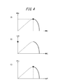
- FIG. 4 is a diagram showing current values and voltage values detected by the current sensors 42A to 42C and the voltage sensors 44A to 44C in the transformers 12A to 12C shown in FIG.
- FIG. 4A is a graph showing the operating state of the solar cell string 20A detected by the transformer 12A.
- FIG. 4B is a graph showing the operating state of the solar cell string 20B detected in the transformer 12B.
- FIG. 4C is a graph showing the operating state of the solar cell string 20C detected by the transformer 12C.
- FIG. 5 is a diagram showing an example of the operation of the power control system 1 following FIG.
- the switching element 32B is not functioning properly and the diode 34B also has some trouble such as a failure.
- the diode 34B is installed to prevent the backflow of the power output from the transformer 12B. For this reason, various inconveniences are assumed when the diode 34B cannot properly prevent the backflow.
- the electric power generated by the solar cell string 20A flows back to the transformer 12B via the transformer 12A and returns from the transformer 12B to the transformer 12A. come.
- the electric power generated by the solar cell string 20A is indicated by a thick solid line.
- the power generated by the solar cell string 20C flows back to the transformer 12B via the transformer 12C, and flows from the transformer 12B to the transformer 12C. Come back.
- the electric power generated by the solar cell string 20C is indicated by a thick broken line.
- FIG. 5 shows an example in which the power control system 1 includes three solar cell strings. However, as the number of solar cell strings increases, inconveniences such as heat generation may increase in such a situation.
- FIG. 6 is a diagram showing current values and voltage values detected by the current sensors 42A to 42C and the voltage sensors 44A to 44C in the transformers 12A to 12C shown in FIG.
- the meaning content of the graph shown in FIG. 6 is the same as that of FIG.
- FIG. 6 if the diode 34B is not functioning properly, the power output from the transformers 12A and 12C is also short-circuited, and the voltage is zero. And the maximum current flows.
- FIG. 6A, FIG. 6B, and FIG. 6C are all short-circuited, indicating that the voltage is zero and the maximum current flows. That is, in this situation, not only the power generated by the solar cell string 20B but also the power generated by the solar cell strings 20A and 20C, although the fault occurs only in the transformer 12B, It cannot be used properly.
- the power control system 1 performs the operation described below in order to eliminate the above-described inconvenience.
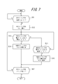
- FIG. 7 is a flowchart for explaining the operation of the power control apparatus 5 according to the present embodiment.
- control unit 10 is controlled to close all the switches 40A to 40C so that the power control system 1 can perform normal operation.
- the power control system 1 starts operation, and the solar cell strings 20A to 20C start power generation.
- the power control device 5 may perform control so as to start operation when the voltage value detected by each of the voltage sensors 44A to 44C exceeds a voltage value defined in advance as the activation determination voltage. Good.
- the control unit 10 determines whether or not the voltage value V of the power generated by the solar cell strings 20A to 20C is equal to or greater than the first threshold value ⁇ 1 (step S11).
- the first threshold value ⁇ 1 prescribes an appropriate value in advance as the voltage value of the power generated by the solar cell strings 20A to 20C for determining whether or not the power control system 1 continues to operate. . If it is below this threshold value ⁇ 1, a low voltage is defined to such an extent that it can be determined that some problem has occurred in the transformer that is transforming the power generated by the solar cell string. If the voltage value V of the power generated by the solar cell strings 20A to 20C in step S11 is equal to or greater than the first threshold value ⁇ 1, the control unit 10 continues the operation of the power control system 1.
- FIG. 8 is a diagram showing current values and voltage values detected by the current sensors 42A to 42C and the voltage sensors 44A to 44C in the transformers 12A to 12C, respectively.
- the meaning content of the graph shown in FIG. 8 is the same as that of FIG.
- the transformers 12A to 12C corresponding to the solar cell strings 20A to 20C are operating normally, the voltage values detected by the voltage sensors 44A to 44C are equal to or greater than the threshold value ⁇ 1. It has become. In such a case, the transformers 12A to 12C can determine that the power generated by the solar cell strings 20A to 20C can be transformed by an appropriate MPPT operation.
- step S11 if the voltage value V of the electric power generated by any one of the solar cell strings 20A to 20C is lower than the first threshold value ⁇ 1 in step S11, the control unit 10 controls all the switches 40A to 40C of the transformer units 12A to 12C. Is controlled to open (step S12). As a result, the power generated by the other solar cell strings is prevented from flowing back to the transformer unit where the malfunction occurs. Therefore, according to the present embodiment, inconveniences such as generation of heat due to a large current flowing through the transformer section where the problem has occurred are solved.
- the control unit 10 determines that the diode 34 has not prevented the backflow of the power output from the transformation unit 12 in any of the plurality of transformation units 12, the plurality of transformation units 10. It controls so that all the switches 40 of the part 12 may be in an open state. At this time, when the voltage value detected by the voltage sensor 44 is lower than the first threshold value in any one of the plurality of transformers 12, the control unit 10 causes the diode 34 to output the power output from the transformer 12. It may be determined that backflow cannot be prevented.
- step S13 the control unit 10 determines whether or not the following conditions are satisfied in each of the transformers 12A to 12C (step S13). That is, in step S13, the control unit 10 determines that the voltage value V detected by the voltage sensors 44A to 44C is equal to or greater than the second threshold value ⁇ 2, and the current value I detected by the current sensors 42A to 42C is the third threshold value. It is determined whether or not ⁇ or less.
- the switches 40A to 40C are opened in step S12, if no malfunction has occurred in each of the transformers 12A to 12C, a certain level of voltage is detected in the transformer as shown in FIG. 8B. And a substantially zero current is detected.
- the second threshold value ⁇ 2 of the voltage is set in advance as an appropriate threshold value that can be determined to be able to be activated again so that the transformer functioning normally can be determined.
- this threshold value ⁇ 2 can be a threshold value of a voltage smaller than the threshold value ⁇ 1.
- the third threshold value ⁇ of current is set in advance to an appropriate threshold value that can determine that almost no current is generated. This threshold value ⁇ can be a current threshold value close to zero, as shown in FIG.
- step S13 If it is determined in step S13 that the above-described condition is satisfied, it can be considered that the transformer 12 can appropriately transform the power generated by the corresponding solar cell string 20. Therefore, in this case, the control unit 10 controls the switch 40 of the transformer 12 to be closed (step S14). Thereby, the transformation part 12 which has not caused abnormality can continue the transformation of the electric power generated by the corresponding solar cell string 20 thereafter.
- the control unit 10 includes the switch 40 of the transformer unit 12 other than the transformer unit 12 having the diode 34 that is determined not to prevent the backflow of power among the plurality of transformer units 12. You may control to make it a closed state.
- the control unit 10 opens all the switches 40 of the plurality of transformers 12, and then the voltage value detected by the voltage sensor 44 in any of the plurality of transformers 12 is the second threshold value.
- the switch 40 of the transformer 12 may be controlled to be closed.
- step S15 the control unit 10 determines whether or not the following condition is satisfied in each of the transformers 12A to 12C (step S15). That is, in step S15, the control unit 10 determines that the voltage value V detected by the voltage sensors 44A to 44C is lower than the second threshold value ⁇ 2, and the current value I detected by the current sensors 42A to 42C is the third threshold value ⁇ . It is determined whether or not.
- step S12 After the switches 40A to 40C are opened in step S12, if a malfunction occurs in each of the transformers 12A to 12C, the voltage at the transformer is zero as shown in FIG. 8C. And that the current is maximized. In this manner, the second threshold value ⁇ 2 for the voltage and the third threshold value ⁇ for the current are set in advance so that the transformer unit having an abnormality can be determined.
- step S15 If it is determined in step S15 that the above-described condition is satisfied, it can be considered that the transformer 12 cannot appropriately transform the power generated by the corresponding solar cell string 20. Therefore, in this case, the control unit 10 controls the switch 40 of the transformer 12 to remain open (step S16).
- the control unit 10 may perform control so as to notify an error as appropriate in order to notify the user that an abnormality has been detected in the transformer 12 that has opened the switch 40.
- the error notification may indicate the error by specifying the transformer 12 on a display unit provided in the power control device 5 or the like, or may be notified by a sound such as a buzzer at the same time. Further, for example, an error may be notified to a predetermined location via a network or the like.
- step S15 if it determines with the conditions mentioned above not being satisfy
- the control unit 10 opens all the switches 40 of the plurality of transformers 12 and then detects the voltage detected by the voltage sensor 44 in any of the plurality of transformers 12.
- the switch 40 of the transformer 12 may be controlled to remain open. .
- Step S13 to Step S16 it is assumed that the above operations from Step S13 to Step S16 are performed for all of the transformers 12A to 12C corresponding to the solar cell strings 20A to 20C, respectively. For this reason, when the normality or abnormality check is completed for the transformers 12A to 12C corresponding to all the solar cell strings 20A to 20C in Step S17, the power control device 5 ends the operation according to the present embodiment. On the other hand, in step S17, when there is a solar cell string 20 that has not yet been checked for normality or abnormality for the transformer 12, the control unit 10 returns to step S13 and continues the check.
- FIG. 9 is a diagram for explaining an operation when a failure occurs in an element in the power control device 5 in the power control system 1 according to the present embodiment.
- FIG. 9 shows a situation similar to that described with reference to FIG. 5, that is, a situation in which a failure occurs in the switching element 32B and the diode 34B in the transformer 12B.
- the switch 40B when the operation described in the flowchart of FIG. 7 is performed, the switch 40B is maintained in the open state only in the transformer 12B including the diode 34B in which the failure has occurred.
- the switches 40A and 40C are switched to the closed state in the transformers 12A and 12C where no malfunction has occurred.
- the transformer 12B including the defective diode 34B cannot transform the power generated by the solar cell string 20B.
- the transformers 12A and 12C in which no malfunction has occurred can appropriately transform and output the power generated by the solar cell strings 20A and 20B again.
- FIG. 10 is a diagram showing current values and voltage values detected by the current sensors 42A to 42C and the voltage sensors 44A to 44C in the transformers 12A to 12C shown in FIG. 9, respectively.
- the meaning contents of the graph shown in FIG. 10 are the same as those in FIGS.
- FIG. 10 (B) if the diode 34B shown in FIG. 9 is not functioning properly, the power is short-circuited in the transformer 12B, and the voltage detected in the transformer 12B becomes zero. Current is maximized. Thus, the transformer 12B cannot appropriately transform the power generated by the solar cell string 20B.
- FIGS. 10 (A) and 10 (C) even if the transformer 12B is not functioning properly, if the transformers 12A and 12C are operating normally, these are the solar cell strings. The electric power generated by 20A and 20C can be transformed by the MPPT operation. In this situation, only the transformer 12B has a problem, and the electric power generated by the solar cell strings 20A and 20C can be used appropriately.
- the present invention all the switch strings are opened, all the solar cell strings are disconnected, and the current sensor provided in the circuit is used to identify the transformer section through which a large current flows.
- the power control device 5 issues a failure notification to the outside, and controls so that the switch of the target transformer is kept open without being closed.
- the user can use a solar other than the solar battery string connected to the damaged transformer part for a period until the maintenance worker performs recovery.
- the maximum power generated by the battery string can be enjoyed.
- the present invention by stopping only the DC / DC converter in which the failure has occurred, the user can maximize the power generated by the other solar cell strings until the DC / DC converter is repaired. Can be enjoyed.
- the reliability and maintenance characteristics of the power control system in which a plurality of solar cell strings are connected can be remarkably improved.
- each functional unit each means, each step, etc.
- the functions included in each functional unit, each means, each step, etc. can be rearranged so that there is no logical contradiction, and a plurality of functional units, steps, etc. are combined or divided. It is possible.
- the above-described embodiments of the present invention are not limited to being performed faithfully to the respective embodiments described above, and can be implemented by appropriately combining the features.
- the present invention can also be implemented as a power control method in the power control system as described above.
- the method In any one of the plurality of transformers 12, a determination step of determining that the diode 34 has not prevented the backflow of the power output from the transformer 12; In the determination step, if it is determined that the diode 34 cannot prevent the backflow of the electric power output from the transformer 12, the opening step of opening all the switches 40 of the plurality of transformers 12; And a closing step of closing the switch 40 of the transformer 12 other than the transformer 12 having a diode determined to be unable to prevent backflow of power among the plurality of transformers 12 after the opening step.
- a power control device According to a power control device, a power control system, and a power control method for controlling power generated by a plurality of solar cell strings according to an embodiment of the present invention, it is possible to improve inconvenience when a failure occurs in an element in the device. Can do.
- Computer systems and other hardware include, for example, general purpose computers, PCs (personal computers), dedicated computers, workstations, PCS (Personal Communications Systems), electronic notepads, laptop computers, or other programs Possible data processing devices are included.
- the various operations are performed by dedicated circuitry (eg, individual logic gates interconnected to perform specific functions) or one or more processors implemented with program instructions (software). Note that it is executed by a logical block or a program module to be executed.
- processors that execute logic blocks or program modules include, for example, one or more microprocessors, CPU (central processing unit), ASIC (Application Specific Integrated Circuit), DSP (Digital Signal Processor), PLD (Programmable Logic Device), FPGA (Field Programmable Gate Array), controller, microcontroller, electronic device, other devices designed to perform the functions described herein, and / or any combination thereof.
- CPU central processing unit
- ASIC Application Specific Integrated Circuit
- DSP Digital Signal Processor
- PLD Programmable Logic Device
- FPGA Field Programmable Gate Array
- controller microcontroller
- electronic device other devices designed to perform the functions described herein, and / or any combination thereof.
- the illustrated embodiments are implemented, for example, by hardware, software, firmware, middleware, microcode, or any combination thereof.
- the machine-readable non-transitory storage medium used here can be further configured as a computer-readable tangible carrier (medium) composed of solid state memory, magnetic disk and optical disk.
- a medium stores an appropriate set of computer instructions such as program modules for causing a processor to execute the technology disclosed herein, and a data structure.
- Computer readable media include electrical connections with one or more wires, magnetic disk storage media, and other magnetic and optical storage devices (eg, CD (Compact Disk), DVD (registered trademark) (Digital Versatile Disk) ), Blu-ray Disc), portable computer disc, RAM (Random Access Memory), ROM (Read-Only Memory), EPROM, EEPROM, flash memory, etc. Tangible storage media or any combination thereof is included.
- the memory can be provided inside and / or outside the processor / processing unit.
- the term “memory” means any type of long-term storage, short-term storage, volatile, non-volatile, or other memory in which a particular type or number of memories or storage is stored. The type of medium is not limited.
Abstract
Description
複数の太陽電池ストリングによって発電される電力をそれぞれ変圧してインバータに出力する複数の変圧部と、
前記複数の変圧部を制御する制御部と、を備え、
前記複数の変圧部のそれぞれは、前記変圧部から出力される電力の逆流を防止するダイオード、および前記太陽電池ストリングと前記インバータとの接続を開閉する開閉器を有し、
前記制御部は、前記複数の変圧部のいずれかのダイオードが対応する前記変圧部から出力される電力の逆流を防止できていない場合に、前記複数の変圧部の全ての開閉器を開状態にした後、前記電力の逆流を防止できていないダイオードを有する変圧部以外の変圧部の開閉器を閉状態にするように制御する。 The power control apparatus according to the first aspect is
A plurality of transformers each transforming the electric power generated by the plurality of solar cell strings and outputting to the inverter;
A controller that controls the plurality of transformers,
Each of the plurality of transformers includes a diode that prevents backflow of power output from the transformer, and a switch that opens and closes a connection between the solar cell string and the inverter.
The control unit opens all the switches of the plurality of transformers when the diode of any of the plurality of transformers cannot prevent the backflow of power output from the corresponding transformer. After that, control is performed so that the switches of the transformer other than the transformer having the diode that cannot prevent the backflow of the electric power are closed.
複数の太陽電池ストリングと、電力制御装置と、を含み、
前記電力制御装置は、
前記複数の太陽電池ストリングによって発電される電力をそれぞれ変圧してインバータに出力する複数の変圧部と、
前記複数の変圧部を制御する制御部と、を備え、
前記複数の変圧部のそれぞれは、前記変圧部から出力される電力の逆流を防止するダイオード、および前記太陽電池ストリングと前記インバータとの接続を開閉する開閉器を備え、
前記制御部は、前記複数の変圧部のいずれかのダイオードが対応する前記変圧部から出力される電力の逆流を防止できていない場合に、前記複数の変圧部の全ての開閉器を開状態にした後、前記電力の逆流を防止できていないダイオードを有する変圧部以外の変圧部の開閉器を閉状態にするように制御する。 The power control system according to the second aspect is
A plurality of solar cell strings and a power control device,
The power control device
A plurality of transformers that respectively transform the electric power generated by the plurality of solar cell strings and output to the inverter;
A controller that controls the plurality of transformers,
Each of the plurality of transformers includes a diode that prevents a reverse flow of power output from the transformer, and a switch that opens and closes a connection between the solar cell string and the inverter.
The control unit opens all the switches of the plurality of transformers when the diode of any of the plurality of transformers cannot prevent the backflow of power output from the corresponding transformer. After that, control is performed so that the switches of the transformer other than the transformer having the diode that cannot prevent the backflow of the electric power are closed.
複数の太陽電池ストリングによって発電される電力をそれぞれ変圧してインバータに出力する複数の変圧部を有する電力制御装置における電力制御方法であって、
前記複数の変圧部のそれぞれは、前記変圧部から出力される電力の逆流を防止するダイオード、および前記太陽電池ストリングと前記インバータとの接続を開閉する開閉器を有し、
前記複数の変圧部のいずれかにおいて、前記ダイオードが当該変圧部から出力される電力の逆流を防止できていないことを判定する判定ステップと、
前記判定ステップにおいて、前記ダイオードが当該変圧部から出力される電力の逆流を防止できていないと判定されたら、前記複数の変圧部の全ての開閉器を開状態にする開ステップと、
前記開ステップに次いで、前記複数の変圧部のうち前記電力の逆流を防止できていないと判定されたダイオードを有する変圧部以外の変圧部の開閉器を閉状態にする閉ステップと、を含む。 The power control method according to the third aspect is:
A power control method in a power control apparatus having a plurality of transformers that transforms and outputs power generated by a plurality of solar cell strings to an inverter, respectively.
Each of the plurality of transformers includes a diode that prevents backflow of power output from the transformer, and a switch that opens and closes a connection between the solar cell string and the inverter.
In any one of the plurality of transformers, a determination step of determining that the diode cannot prevent a backflow of power output from the transformer,
In the determining step, if it is determined that the diode cannot prevent the backflow of the power output from the transformer, an opening step of opening all the switches of the plurality of transformers;
And a closing step of closing a switch of a transformer other than the transformer having a diode determined not to prevent backflow of the electric power among the plurality of transformers after the opening step.
この場合、前記方法は、
複数の変圧部12のいずれかにおいて、ダイオード34が当該変圧部12から出力される電力の逆流を防止できていないことを判定する判定ステップと、
判定ステップにおいて、ダイオード34が当該変圧部12から出力される電力の逆流を防止できていないと判定されたら、複数の変圧部12の全ての開閉器40を開状態にする開ステップと、
開ステップに次いで、複数の変圧部12のうち電力の逆流を防止できていないと判定されたダイオードを有する変圧部12以外の変圧部12の開閉器40を閉状態にする閉ステップと、を含む。 The power control apparatus according to the present embodiment and the power control system including the power control apparatus have been described above, but the present invention can also be implemented as a power control method in the power control system as described above.
In this case, the method
In any one of the plurality of transformers 12, a determination step of determining that the diode 34 has not prevented the backflow of the power output from the transformer 12;
In the determination step, if it is determined that the diode 34 cannot prevent the backflow of the electric power output from the transformer 12, the opening step of opening all the switches 40 of the plurality of transformers 12;
And a closing step of closing the switch 40 of the transformer 12 other than the transformer 12 having a diode determined to be unable to prevent backflow of power among the plurality of transformers 12 after the opening step. .
5 電力制御装置
10 制御部
12 変圧部
14 インバータ
16 フィルタ部
20 太陽電池ストリング
30 コイル
32 スイッチング素子
34 ダイオード
36,38 コンデンサ
40 開閉器
42 電流センサ
44 電圧センサ
50 負荷
60 系統 DESCRIPTION OF SYMBOLS 1
Claims (12)
- 複数の太陽電池ストリングによって発電される電力をそれぞれ変圧してインバータに出力する複数の変圧部と、
前記複数の変圧部を制御する制御部と、を備え、
前記複数の変圧部のそれぞれは、前記変圧部から出力される電力の逆流を防止するダイオード、および前記太陽電池ストリングと前記インバータとの接続を開閉する開閉器を有し、
前記制御部は、前記複数の変圧部のいずれかのダイオードが対応する前記変圧部から出力される電力の逆流を防止できていない場合に、前記複数の変圧部の全ての開閉器を開状態にした後、前記電力の逆流を防止できていないダイオードを有する変圧部以外の変圧部の開閉器を閉状態にするように制御することを特徴とする、電力制御装置。 A plurality of transformers each transforming the electric power generated by the plurality of solar cell strings and outputting to the inverter;
A controller that controls the plurality of transformers,
Each of the plurality of transformers includes a diode that prevents backflow of power output from the transformer, and a switch that opens and closes a connection between the solar cell string and the inverter.
The control unit opens all the switches of the plurality of transformers when the diode of any of the plurality of transformers cannot prevent the backflow of power output from the corresponding transformer. After that, the power control device is controlled so as to close a switch of a transformer other than the transformer having a diode that cannot prevent backflow of the power. - 前記複数の変圧部のそれぞれは、前記変圧部に対応して接続された太陽電池ストリングによって発電される電力の電圧値を検出する電圧センサを有し、
前記制御部は、前記複数の変圧部のいずれかにおいて、前記電圧センサによって検出される電圧値が第1の閾値を下回った場合、前記ダイオードが前記変圧部から出力される電力の逆流を防止できていないと判定する、請求項1に記載の電力制御装置。 Each of the plurality of transformers includes a voltage sensor that detects a voltage value of electric power generated by a solar cell string connected corresponding to the transformer.
The control unit can prevent backflow of power output from the transformer when the voltage value detected by the voltage sensor is lower than a first threshold in any of the plurality of transformers. The power control device according to claim 1, wherein the power control device is determined not to be. - 前記複数の変圧部のそれぞれは、前記変圧部に対応して接続された太陽電池ストリングによって発電される電力の電流値を検出する電流センサを有し、
前記制御部は、前記複数の変圧部の全ての開閉器を開状態にした後、前記電圧センサによって検出される電圧値が第2の閾値以上であり、かつ前記電流センサによって検出される電流値が第3の閾値以下の変圧部の開閉器を閉状態にするように制御する、請求項2に記載の電力制御装置。 Each of the plurality of transformers includes a current sensor that detects a current value of electric power generated by the solar cell string connected corresponding to the transformer.
The controller, after opening all the switches of the plurality of transformers, a voltage value detected by the voltage sensor is equal to or greater than a second threshold, and a current value detected by the current sensor The power control device according to claim 2, wherein control is performed so that the switch of the transformer unit having a value equal to or smaller than a third threshold is closed. - 前記複数の変圧部のそれぞれは、前記変圧部に対応して接続された太陽電池ストリングによって発電される電力の電流値を検出する電流センサを有し、
前記制御部は、前記複数の変圧部の全ての開閉器を開状態にした後、前記複数の変圧部のいずれかにおいて、前記電圧センサによって検出される電圧値が第2の閾値を下回り、かつ前記電流センサによって検出される電流値が第3の閾値を超える変圧部の開閉器を開状態にしたままにするように制御する、請求項2に記載の電力制御装置。 Each of the plurality of transformers includes a current sensor that detects a current value of electric power generated by the solar cell string connected corresponding to the transformer.
The controller, after opening all the switches of the plurality of transformers, in any of the plurality of transformers, the voltage value detected by the voltage sensor is less than a second threshold, and The power control apparatus according to claim 2, wherein control is performed so that a switch of a transformer unit in which a current value detected by the current sensor exceeds a third threshold is left open. - 複数の太陽電池ストリングと、電力制御装置と、を含む電力制御システムであって、
前記電力制御装置は、
前記複数の太陽電池ストリングによって発電される電力をそれぞれ変圧してインバータに出力する複数の変圧部と、
前記複数の変圧部を制御する制御部と、を備え、
前記複数の変圧部のそれぞれは、前記変圧部から出力される電力の逆流を防止するダイオード、および前記太陽電池ストリングと前記インバータとの接続を開閉する開閉器を備え、
前記制御部は、前記複数の変圧部のいずれかのダイオードが対応する前記変圧部から出力される電力の逆流を防止できていない場合に、前記複数の変圧部の全ての開閉器を開状態にした後、前記電力の逆流を防止できていないダイオードを有する変圧部以外の変圧部の開閉器を閉状態にするように制御することを特徴とする、電力制御システム。 A power control system including a plurality of solar cell strings and a power control device,
The power control device
A plurality of transformers that respectively transform the electric power generated by the plurality of solar cell strings and output to the inverter;
A controller that controls the plurality of transformers,
Each of the plurality of transformers includes a diode that prevents a reverse flow of power output from the transformer, and a switch that opens and closes a connection between the solar cell string and the inverter.
The control unit opens all the switches of the plurality of transformers when the diode of any of the plurality of transformers cannot prevent the backflow of power output from the corresponding transformer. After that, the power control system is characterized in that control is performed so that a switch of a transformer other than the transformer having a diode that cannot prevent backflow of power is closed. - 前記複数の変圧部のそれぞれは、前記変圧部に対応して接続された太陽電池ストリングによって発電される電力の電圧値を検出する電圧センサを有し、
前記制御部は、前記複数の変圧部のいずれかにおいて、前記電圧センサによって検出される電圧値が第1の閾値を下回った場合、前記ダイオードが前記変圧部から出力される電力の逆流を防止できていないと判定する、請求項5に記載の電力制御システム。 Each of the plurality of transformers includes a voltage sensor that detects a voltage value of electric power generated by a solar cell string connected corresponding to the transformer.
The control unit can prevent backflow of power output from the transformer when the voltage value detected by the voltage sensor is lower than a first threshold in any of the plurality of transformers. The power control system according to claim 5, wherein the power control system is determined not to be. - 前記複数の変圧部のそれぞれは、前記変圧部に対応して接続された太陽電池ストリングによって発電される電力の電流値を検出する電流センサを有し、
前記制御部は、前記複数の変圧部の全ての開閉器を開状態にした後、前記電圧センサによって検出される電圧値が第2の閾値以上であり、かつ前記電流センサによって検出される電流値が第3の閾値以下の変圧部の開閉器を閉状態にするように制御する、請求項6に記載の電力制御システム。 Each of the plurality of transformers includes a current sensor that detects a current value of electric power generated by the solar cell string connected corresponding to the transformer.
The controller, after opening all the switches of the plurality of transformers, a voltage value detected by the voltage sensor is equal to or greater than a second threshold, and a current value detected by the current sensor The power control system according to claim 6, wherein control is performed so as to close a switch of a transformer unit having a value equal to or smaller than a third threshold. - 前記複数の変圧部のそれぞれは、前記変圧部に対応して接続された太陽電池ストリングによって発電される電力の電流値を検出する電流センサを有し、
前記制御部は、前記複数の変圧部の全ての開閉器を開状態にした後、前記複数の変圧部のいずれかにおいて、前記電圧センサによって検出される電圧値が第2の閾値を下回り、かつ前記電流センサによって検出される電流値が第3の閾値を超える変圧部の開閉器を開状態にしたままにするように制御する、請求項6に記載の電力制御システム。 Each of the plurality of transformers includes a current sensor that detects a current value of electric power generated by the solar cell string connected corresponding to the transformer.
The controller, after opening all the switches of the plurality of transformers, in any of the plurality of transformers, the voltage value detected by the voltage sensor is less than a second threshold, and The power control system according to claim 6, wherein control is performed such that a switch of a transformer unit in which a current value detected by the current sensor exceeds a third threshold is left open. - 複数の太陽電池ストリングによって発電される電力をそれぞれ変圧してインバータに出力する複数の変圧部を有する電力制御装置における電力制御方法であって、
前記複数の変圧部のそれぞれは、前記変圧部から出力される電力の逆流を防止するダイオード、および前記太陽電池ストリングと前記インバータとの接続を開閉する開閉器を有し、
前記複数の変圧部のいずれかにおいて、前記ダイオードが当該変圧部から出力される電力の逆流を防止できていないことを判定する判定ステップと、
前記判定ステップにおいて、前記ダイオードが当該変圧部から出力される電力の逆流を防止できていないと判定されたら、前記複数の変圧部の全ての開閉器を開状態にする開ステップと、
前記開ステップに次いで、前記複数の変圧部のうち前記電力の逆流を防止できていないと判定されたダイオードを有する変圧部以外の変圧部の開閉器を閉状態にする閉ステップと、を含むことを特徴とする電力制御方法。 A power control method in a power control apparatus having a plurality of transformers that transforms and outputs power generated by a plurality of solar cell strings to an inverter, respectively.
Each of the plurality of transformers includes a diode that prevents backflow of power output from the transformer, and a switch that opens and closes a connection between the solar cell string and the inverter.
In any one of the plurality of transformers, a determination step of determining that the diode cannot prevent a backflow of power output from the transformer,
In the determining step, if it is determined that the diode cannot prevent the backflow of the power output from the transformer, an opening step of opening all the switches of the plurality of transformers;
A step of closing a switch of a transformer other than the transformer having a diode determined not to prevent backflow of the electric power among the plurality of transformers, after the opening step. A power control method characterized by the above. - 前記複数の変圧部のそれぞれは、前記変圧部に対応して接続された太陽電池ストリングによって発電される電力の電圧値を検出する電圧センサを有し、
前記判定ステップでは、前記複数の変圧部のいずれかにおいて、前記電圧センサによって検出される電圧値が第1の閾値を下回った場合、前記ダイオードが前記変圧部から出力される電力の逆流を防止できていないと判定する、請求項9に記載の電力制御方法。 Each of the plurality of transformers includes a voltage sensor that detects a voltage value of electric power generated by a solar cell string connected corresponding to the transformer.
In the determination step, when the voltage value detected by the voltage sensor is lower than a first threshold value in any of the plurality of transformers, the diode can prevent a reverse flow of power output from the transformer. The power control method according to claim 9, wherein the power control method is determined not to be present. - 前記複数の変圧部のそれぞれは、前記変圧部に対応して接続された太陽電池ストリングによって発電される電力の電流値を検出する電流センサを有し、
前記閉ステップでは、前記開ステップにおいて前記複数の変圧部の全ての開閉器を開状態にした後、前記電圧センサによって検出される電圧値が第2の閾値以上であり、かつ前記電流センサによって検出される電流値が第3の閾値以下の変圧部の開閉器を閉状態にする、請求項10に記載の電力制御方法。 Each of the plurality of transformers includes a current sensor that detects a current value of electric power generated by the solar cell string connected corresponding to the transformer.
In the closing step, after opening all the switches of the plurality of transformers in the opening step, a voltage value detected by the voltage sensor is equal to or greater than a second threshold value and detected by the current sensor. The power control method according to claim 10, wherein a switch of a transformer unit whose current value is equal to or less than a third threshold value is closed. - 前記複数の変圧部のそれぞれは、前記変圧部に対応して接続された太陽電池ストリングによって発電される電力の電流値を検出する電流センサを有し、
前記開ステップにおいて前記複数の変圧部の全ての開閉器を開状態にした後、前記複数の変圧部のいずれかにおいて、前記電圧センサによって検出される電圧値が第2の閾値を下回り、かつ前記電流センサによって検出される電流値が第3の閾値を超える変圧部の開閉器を開状態にしたままにする、請求項10に記載の電力制御方法。 Each of the plurality of transformers includes a current sensor that detects a current value of electric power generated by the solar cell string connected corresponding to the transformer.
After opening all the switches of the plurality of transformers in the opening step, in any of the plurality of transformers, a voltage value detected by the voltage sensor is below a second threshold, and the The power control method according to claim 10, wherein the switch of the transformer unit whose current value detected by the current sensor exceeds the third threshold is left open.
Priority Applications (3)
| Application Number | Priority Date | Filing Date | Title |
|---|---|---|---|
| JP2016571874A JP6450403B2 (en) | 2015-01-28 | 2016-01-28 | Power control apparatus, power control system, and power control method |
| EP16743006.5A EP3252562B1 (en) | 2015-01-28 | 2016-01-28 | Electric power control device, electric power control system, and electric power control method |
| US15/546,444 US10298018B2 (en) | 2015-01-28 | 2016-01-28 | Power control apparatus, power control system, and power control method |
Applications Claiming Priority (2)
| Application Number | Priority Date | Filing Date | Title |
|---|---|---|---|
| JP2015014795 | 2015-01-28 | ||
| JP2015-014795 | 2015-01-28 |
Publications (1)
| Publication Number | Publication Date |
|---|---|
| WO2016121402A1 true WO2016121402A1 (en) | 2016-08-04 |
Family
ID=56543024
Family Applications (1)
| Application Number | Title | Priority Date | Filing Date |
|---|---|---|---|
| PCT/JP2016/000448 WO2016121402A1 (en) | 2015-01-28 | 2016-01-28 | Electric power control device, electric power control system, and electric power control method |
Country Status (4)
| Country | Link |
|---|---|
| US (1) | US10298018B2 (en) |
| EP (1) | EP3252562B1 (en) |
| JP (1) | JP6450403B2 (en) |
| WO (1) | WO2016121402A1 (en) |
Cited By (1)
| Publication number | Priority date | Publication date | Assignee | Title |
|---|---|---|---|---|
| JP2019022326A (en) * | 2017-07-18 | 2019-02-07 | Mers Fors株式会社 | Solar cell group and solar power generation system |
Families Citing this family (6)
| Publication number | Priority date | Publication date | Assignee | Title |
|---|---|---|---|---|
| JP6450403B2 (en) * | 2015-01-28 | 2019-01-09 | 京セラ株式会社 | Power control apparatus, power control system, and power control method |
| JP6943668B2 (en) * | 2017-07-28 | 2021-10-06 | ローム株式会社 | Electronics |
| WO2020259801A1 (en) * | 2019-06-25 | 2020-12-30 | Huawei Technologies Co., Ltd. | A dc-to-dc power converter |
| US11855445B2 (en) * | 2019-07-11 | 2023-12-26 | Mitsubishi Electric Corporation | Power conversion device |
| CN110888085A (en) * | 2019-11-29 | 2020-03-17 | 华为数字技术(苏州)有限公司 | Inverter short circuit detection method and device and inverter |
| CN111262767B (en) * | 2020-03-27 | 2022-11-15 | 阳光电源股份有限公司 | Photovoltaic system and communication method thereof |
Citations (2)
| Publication number | Priority date | Publication date | Assignee | Title |
|---|---|---|---|---|
| JP2005065466A (en) * | 2003-08-20 | 2005-03-10 | Mitsubishi Electric Corp | Voltage fluctuation compensation device |
| JP2014063282A (en) * | 2012-09-20 | 2014-04-10 | Kyocera Corp | Power conditioner and method of controlling the same |
Family Cites Families (54)
| Publication number | Priority date | Publication date | Assignee | Title |
|---|---|---|---|---|
| JP3329168B2 (en) | 1995-01-13 | 2002-09-30 | オムロン株式会社 | Backflow prevention device |
| US8102144B2 (en) * | 2003-05-28 | 2012-01-24 | Beacon Power Corporation | Power converter for a solar panel |
| JP2005151664A (en) * | 2003-11-13 | 2005-06-09 | Nissan Motor Co Ltd | Switched reluctance motor drive controller |
| WO2007097012A1 (en) * | 2006-02-27 | 2007-08-30 | Fujitsu Limited | Power supply apparatus and control method therefor |
| US9130401B2 (en) * | 2006-12-06 | 2015-09-08 | Solaredge Technologies Ltd. | Distributed power harvesting systems using DC power sources |
| US9088178B2 (en) * | 2006-12-06 | 2015-07-21 | Solaredge Technologies Ltd | Distributed power harvesting systems using DC power sources |
| US8158877B2 (en) * | 2007-03-30 | 2012-04-17 | Sunpower Corporation | Localized power point optimizer for solar cell installations |
| US9407093B2 (en) * | 2007-08-22 | 2016-08-02 | Maxout Renewables, Inc. | Method for balancing circuit voltage |
| EP2330728A4 (en) * | 2008-09-22 | 2014-11-26 | Fujitsu Ltd | Power control circuit, power supply unit, power supply system, and power controller control method |
| JP4985873B2 (en) | 2009-04-23 | 2012-07-25 | トヨタ自動車株式会社 | Electric vehicle power supply system and control method thereof |
| DE112009004962B4 (en) * | 2009-06-18 | 2017-02-09 | Toyota Jidosha Kabushiki Kaisha | Device for detecting a short circuit of an output diode in a converter |
| JP2011015501A (en) * | 2009-06-30 | 2011-01-20 | Panasonic Electric Works Co Ltd | Power distribution system |
| JP5479182B2 (en) * | 2009-09-30 | 2014-04-23 | 三洋電機株式会社 | Power generation system and charge / discharge control device |
| WO2011078215A1 (en) * | 2009-12-22 | 2011-06-30 | 三洋電機株式会社 | Electric-power supply method, computer-readable recording medium, and electric-power generating system |
| JP5475019B2 (en) * | 2010-01-28 | 2014-04-16 | 三洋電機株式会社 | Power supply method, computer-readable recording medium, and power generation system |
| WO2011122592A1 (en) * | 2010-03-30 | 2011-10-06 | 三洋電機株式会社 | Power storage unit, method for correcting capacity value of storage battery, and power storage system |
| US8842397B2 (en) * | 2011-05-23 | 2014-09-23 | Microsemi Corporation | Photo-voltaic safety de-energizing device |
| JP5792552B2 (en) * | 2011-08-03 | 2015-10-14 | ラピスセミコンダクタ株式会社 | Power supply control system and semiconductor integrated circuit |
| US8508074B2 (en) * | 2011-10-28 | 2013-08-13 | The Board Of Trustees Of The University Of Illinois | System and method for optimizing solar power conversion |
| US9461474B2 (en) * | 2012-01-17 | 2016-10-04 | Infineon Technologies Austria Ag | Power converter circuit with AC output |
| US20140042815A1 (en) * | 2012-06-10 | 2014-02-13 | The Regents of the University of Colorado, A Body Corporate | Balancing, filtering and/or controlling series-connected cells |
| JP5335117B1 (en) * | 2012-06-18 | 2013-11-06 | 株式会社椿本チエイン | Power control device |
| JP5841906B2 (en) * | 2012-07-03 | 2016-01-13 | Jx日鉱日石エネルギー株式会社 | Failure detection device, failure detection system, and failure detection method |
| CN204614723U (en) * | 2012-08-30 | 2015-09-02 | 三洋电机株式会社 | Input circuit and power inverter |
| US9923398B2 (en) * | 2013-03-22 | 2018-03-20 | Panasonic Intellectual Property Management Co., Ltd. | Electricity-storage system, monitoring device, and power control system |
| US20140306542A1 (en) * | 2013-04-11 | 2014-10-16 | Draker, Inc. | Switch Disconnect Circuit for Solar Arrays |
| US9906037B2 (en) * | 2013-04-13 | 2018-02-27 | Honey Badger International Pty Ltd. | Energy generation load compensation |
| US10615607B2 (en) * | 2013-05-01 | 2020-04-07 | Tigo Energy, Inc. | Systems and methods for quick dissipation of stored energy from input capacitors of power inverters |
| EP3035393B1 (en) * | 2013-08-13 | 2018-06-27 | Hitachi Systems, Ltd. | Solar power generation inspection system and solar power generation inspection method |
| GB201316903D0 (en) * | 2013-09-24 | 2013-11-06 | Univ Leuven Kath | An Intra-Module DC-DC Converter |
| JP6135768B2 (en) * | 2013-09-26 | 2017-05-31 | 富士通株式会社 | Step-down power supply circuit, power supply module, and step-down power supply circuit control method |
| WO2015045231A1 (en) * | 2013-09-30 | 2015-04-02 | パナソニックIpマネジメント株式会社 | Photoelectric conversion apparatus and photoelectric conversion unit used in photoelectric conversion apparatus |
| JP6160481B2 (en) * | 2013-12-27 | 2017-07-12 | ソニー株式会社 | Power supply device, power supply system, and power supply control method |
| US10418819B2 (en) * | 2014-07-29 | 2019-09-17 | Kyocera Corporation | Control method for power control system, power control system, and power control apparatus |
| US10976760B2 (en) * | 2016-01-06 | 2021-04-13 | Andreas Hieke | Methods and functional elements for enhanced thermal management of predominantly enclosed spaces and the use of concurrently obtained sensor data for secondary applications including insurance related applications |
| EP3247018A4 (en) * | 2015-01-13 | 2018-10-24 | Toshiba Mitsubishi-Electric Industrial Systems Corporation | Control device for inverter |
| US9780636B2 (en) * | 2015-01-19 | 2017-10-03 | Infineon Technologies Austria Ag | Protection from hard commutation events at power switches |
| JP6450403B2 (en) * | 2015-01-28 | 2019-01-09 | 京セラ株式会社 | Power control apparatus, power control system, and power control method |
| US9859714B2 (en) * | 2015-06-18 | 2018-01-02 | Sparq Systems Inc. | Multiple input three-phase inverter with independent MPPT and high efficiency |
| KR101582825B1 (en) * | 2015-06-30 | 2016-01-07 | 정현아 | Monitoring apparatus for solar cell |
| WO2017056286A1 (en) * | 2015-10-01 | 2017-04-06 | 株式会社東芝 | Power supply system |
| EP3370320A4 (en) * | 2015-10-28 | 2019-03-20 | Kyocera Corporation | Power control system and control method for power control system |
| US10153650B2 (en) * | 2015-12-15 | 2018-12-11 | Intel Corporation | Energy harvesting system for IoT devices |
| JP6525066B2 (en) * | 2016-01-14 | 2019-06-05 | 株式会社村田製作所 | POWER SUPPLY DEVICE AND CONTROL DEVICE |
| JP6011736B1 (en) * | 2016-03-14 | 2016-10-19 | 富士電機株式会社 | Boost chopper circuit |
| JP6529921B2 (en) * | 2016-03-25 | 2019-06-12 | 株式会社日立情報通信エンジニアリング | Power converter |
| US11196272B2 (en) * | 2016-06-29 | 2021-12-07 | Koolbridge Solar, Inc. | Rapid de-energization of DC conductors with a power source at both ends |
| US10020754B2 (en) * | 2016-09-30 | 2018-07-10 | Sunpower Corporation | String inverter system |
| KR102322366B1 (en) * | 2017-03-02 | 2021-11-04 | 현대자동차주식회사 | Solar cell system and control method thereof |
| EP3379710B1 (en) * | 2017-03-24 | 2021-10-27 | Thales | Switching power converter configured to control at least one phase of a polyphase electrical receiver with at least three phases |
| CN108695843B (en) * | 2017-03-29 | 2023-09-22 | 太阳能安吉科技有限公司 | Bypass circuit and method of bypassing power module in power system |
| US10812998B2 (en) * | 2017-04-05 | 2020-10-20 | Sensr Monitoring Technologies Llc | Sensor and monitoring system |
| US10931104B2 (en) * | 2017-05-30 | 2021-02-23 | Solaredge Technologies Ltd. | System and method for interconnected elements of a power system |
| US11569683B2 (en) * | 2017-05-31 | 2023-01-31 | Solaredge Technologies Ltd. | Circuit for a power device and graphical user interface |
-
2016
- 2016-01-28 JP JP2016571874A patent/JP6450403B2/en active Active
- 2016-01-28 WO PCT/JP2016/000448 patent/WO2016121402A1/en active Application Filing
- 2016-01-28 US US15/546,444 patent/US10298018B2/en active Active
- 2016-01-28 EP EP16743006.5A patent/EP3252562B1/en active Active
Patent Citations (2)
| Publication number | Priority date | Publication date | Assignee | Title |
|---|---|---|---|---|
| JP2005065466A (en) * | 2003-08-20 | 2005-03-10 | Mitsubishi Electric Corp | Voltage fluctuation compensation device |
| JP2014063282A (en) * | 2012-09-20 | 2014-04-10 | Kyocera Corp | Power conditioner and method of controlling the same |
Cited By (2)
| Publication number | Priority date | Publication date | Assignee | Title |
|---|---|---|---|---|
| JP2019022326A (en) * | 2017-07-18 | 2019-02-07 | Mers Fors株式会社 | Solar cell group and solar power generation system |
| JP7076764B2 (en) | 2017-07-18 | 2022-05-30 | Mers Fors株式会社 | Solar cell group and solar power generation system |
Also Published As
| Publication number | Publication date |
|---|---|
| EP3252562A4 (en) | 2018-08-22 |
| EP3252562B1 (en) | 2019-12-25 |
| US20180026450A1 (en) | 2018-01-25 |
| JPWO2016121402A1 (en) | 2017-08-31 |
| EP3252562A1 (en) | 2017-12-06 |
| US10298018B2 (en) | 2019-05-21 |
| JP6450403B2 (en) | 2019-01-09 |
Similar Documents
| Publication | Publication Date | Title |
|---|---|---|
| JP6450403B2 (en) | Power control apparatus, power control system, and power control method | |
| JP5344759B2 (en) | Power distribution system | |
| JP6741169B2 (en) | Power supply device, power control device, power supply device relay determination method | |
| US11495966B2 (en) | Solar power generation system and power conditioner | |
| JP6246917B2 (en) | Power supply system, control method for power supply system, and power supply apparatus | |
| JPWO2011158278A1 (en) | DC stabilized power supply | |
| KR102318535B1 (en) | String-optima with string leakage current detection and trip function of solar power generation system | |
| JP6334058B2 (en) | Power supply device control method, power supply device, and power supply system | |
| US11031786B2 (en) | Power convertor, power generation system, and power generation control method | |
| US10418819B2 (en) | Control method for power control system, power control system, and power control apparatus | |
| US20200144918A1 (en) | Power convertor, power generation system, and power generation control method | |
| JP6575633B2 (en) | Photovoltaic power generation system, electric circuit connection method between solar cell modules, and electric circuit release method between solar cell modules | |
| JP6902719B2 (en) | Converter system | |
| JPWO2020183700A1 (en) | Control device and photovoltaic power generation system | |
| JP2020096430A (en) | Electric power conversion device | |
| JP6332244B2 (en) | Photovoltaic power generation system, circuit switch between solar cell modules, and solar cell module | |
| JP6944884B2 (en) | Power supply | |
| JP6242128B2 (en) | Power converter | |
| JP2016201931A (en) | Power Conditioner | |
| JP6385207B2 (en) | Battery system | |
| JP5941495B2 (en) | Power switching circuit | |
| JP6255671B2 (en) | Inverter | |
| JP6043223B2 (en) | Cooperation system of photovoltaic power generation and storage battery | |
| JP7303721B2 (en) | Power storage device and power storage system | |
| JP2016101050A (en) | Booster connection box and power generation system |
Legal Events
| Date | Code | Title | Description |
|---|---|---|---|
| 121 | Ep: the epo has been informed by wipo that ep was designated in this application |
Ref document number: 16743006 Country of ref document: EP Kind code of ref document: A1 |
|
| ENP | Entry into the national phase |
Ref document number: 2016571874 Country of ref document: JP Kind code of ref document: A |
|
| REEP | Request for entry into the european phase |
Ref document number: 2016743006 Country of ref document: EP |
|
| WWE | Wipo information: entry into national phase |
Ref document number: 15546444 Country of ref document: US |
|
| NENP | Non-entry into the national phase |
Ref country code: DE |