US10949059B2 - Controlling movement of an entity displayed on a user interface - Google Patents
Controlling movement of an entity displayed on a user interface Download PDFInfo
- Publication number
- US10949059B2 US10949059B2 US15/161,739 US201615161739A US10949059B2 US 10949059 B2 US10949059 B2 US 10949059B2 US 201615161739 A US201615161739 A US 201615161739A US 10949059 B2 US10949059 B2 US 10949059B2
- Authority
- US
- United States
- Prior art keywords
- displayed
- entity
- location
- user input
- graphical indicators
- Prior art date
- Legal status (The legal status is an assumption and is not a legal conclusion. Google has not performed a legal analysis and makes no representation as to the accuracy of the status listed.)
- Active, expires
Links
Images


Classifications
-
- G—PHYSICS
- G06—COMPUTING OR CALCULATING; COUNTING
- G06F—ELECTRIC DIGITAL DATA PROCESSING
- G06F3/00—Input arrangements for transferring data to be processed into a form capable of being handled by the computer; Output arrangements for transferring data from processing unit to output unit, e.g. interface arrangements
- G06F3/01—Input arrangements or combined input and output arrangements for interaction between user and computer
- G06F3/048—Interaction techniques based on graphical user interfaces [GUI]
- G06F3/0481—Interaction techniques based on graphical user interfaces [GUI] based on specific properties of the displayed interaction object or a metaphor-based environment, e.g. interaction with desktop elements like windows or icons, or assisted by a cursor's changing behaviour or appearance
- G06F3/04817—Interaction techniques based on graphical user interfaces [GUI] based on specific properties of the displayed interaction object or a metaphor-based environment, e.g. interaction with desktop elements like windows or icons, or assisted by a cursor's changing behaviour or appearance using icons
-
- G—PHYSICS
- G06—COMPUTING OR CALCULATING; COUNTING
- G06F—ELECTRIC DIGITAL DATA PROCESSING
- G06F3/00—Input arrangements for transferring data to be processed into a form capable of being handled by the computer; Output arrangements for transferring data from processing unit to output unit, e.g. interface arrangements
- G06F3/01—Input arrangements or combined input and output arrangements for interaction between user and computer
- G06F3/048—Interaction techniques based on graphical user interfaces [GUI]
- G06F3/0481—Interaction techniques based on graphical user interfaces [GUI] based on specific properties of the displayed interaction object or a metaphor-based environment, e.g. interaction with desktop elements like windows or icons, or assisted by a cursor's changing behaviour or appearance
- G06F3/04812—Interaction techniques based on cursor appearance or behaviour, e.g. being affected by the presence of displayed objects
-
- G—PHYSICS
- G06—COMPUTING OR CALCULATING; COUNTING
- G06F—ELECTRIC DIGITAL DATA PROCESSING
- G06F3/00—Input arrangements for transferring data to be processed into a form capable of being handled by the computer; Output arrangements for transferring data from processing unit to output unit, e.g. interface arrangements
- G06F3/01—Input arrangements or combined input and output arrangements for interaction between user and computer
- G06F3/048—Interaction techniques based on graphical user interfaces [GUI]
- G06F3/0487—Interaction techniques based on graphical user interfaces [GUI] using specific features provided by the input device, e.g. functions controlled by the rotation of a mouse with dual sensing arrangements, or of the nature of the input device, e.g. tap gestures based on pressure sensed by a digitiser
- G06F3/0488—Interaction techniques based on graphical user interfaces [GUI] using specific features provided by the input device, e.g. functions controlled by the rotation of a mouse with dual sensing arrangements, or of the nature of the input device, e.g. tap gestures based on pressure sensed by a digitiser using a touch-screen or digitiser, e.g. input of commands through traced gestures
Definitions
- This disclosure relates to controlling an entity displayed on a user interface, particularly but not exclusively to a user interface of a touch screen device, for example in the context of a computer implemented game.
- the input may be a cursor or pointer that is controlled by a human interface device such as a mouse, joystick, keyboard etc.
- the display may comprise a touchscreen which can be controlled by a user's touch. That is, activation of functions or objects are responsive to user input made by way of the user touching the screen.
- Touch screens may be provided on smaller devices such a smart phones. Interaction with objects displayed on such touch screens can be difficult in that the size of a user's finger is relatively large with respect to the area of the screen where for example an object is displayed. This may lead to a lack of precision when for example playing a computer implemented game on a smart phone.
- a computer implemented game is available in which an entity displayed on a user interface of a computer device is a character whose movement is controlled by a user input wherein a user engages with the interface (e.g. a finger on a touch screen). Movement by the user's input causes corresponding movement of the entity.
- the entity can be a character which is pursuing and attacking, or being pursued.
- a method of controlling an entity displayed on a user interface of a computer device the method implemented by computer readable code executed by a processor of the computer device, the method comprising: detecting a user input at a first location on the user interface; detecting that the user input continues along a user input trace to a second location; determining a distance along a direct path between the first and second locations; calculating a speed of movement of the entity based on the determined distance; and generating for display a number of graphical indicators to be displayed on the user interface at locations spaced from one another between the first and second locations, wherein the number of displayed indicators represent the speed of movement of the entity.
- the graphical indicators are displayed along the direct path.
- the direct path can be a linear trace, wherein the trace itself is not displayed on the user interface, but the graphical indicators are displayed aligned along the direct path.
- the graphical indicators may be directional icons which indicate the direction of movement of the entity. These directional icons can be aligned along the direct path.
- the graphical indicators may be spaced from one another between the first and second locations in a manner such that their spacing is in a direction following the direction of the direct path, but wherein the graphical indicators need not necessarily be aligned along a linear trace according to the direct path.
- graphical indicators may be placed on either side of a linear trace corresponding to the direct path, or for example weaving generally in the direction of the direct path between the first and second locations.
- each graphical indicator is an arrow with an arrowhead pointing in the direction of movement.
- An initial part of the user input trace may be a straight line from the first to the second location, in which case the direct path would be determined to match that straight line.
- the number of graphical indicators which are displayed would correspond to the distance determined between the first and second locations along the direct path, and represent the speed of movement of the entity.
- the method can also comprise detecting a change of direction of the user input trace and adjusting a direction of the direct path by pivoting about the first location.
- the path of movement of the entity on the user interface does not follow an L shape, but instead changes the direction of the direct path between the first and second locations so that there is still a straight line.
- the number of displayed indicators along this line represent the speed of movement of the entity and the line indicates the direction of movement of the entity.
- the method can also comprise the steps of controlling the entity to move on the user interface at the calculated speed, and controlling the entity to move on the user interface in the direction indicated by the graphical indicators.
- the method comprises causing a commencement marker to be displayed at the first location.
- the commencement marker can initially indicate the direction of the user input trace. When the direction of the direct path is adjusted, the commencement marker would also be rotated such that it then indicates the direction of the adjusted direct path.
- the commencement marker may for example be a circle with a small arrowhead set into its circumference.
- a first one of the number of graphical indicators may be displayed after a minimum distance from the first location has been attained from the user input.
- a last one of the number of graphical indicators can be displayed after a maximum distance from the first location has been attained by the continued user input. This has the effect that further continued user input does not result in further graphical indicators being displayed after the maximum distance has been attained.
- the first location may be the displayed location of the entity, or it can be a location separate from the displayed location of the entity.
- the method can comprise the step of detecting the continuous user input to increase the distance between the first and second locations and generate an increased number of graphical indicators responsive to the increased distance.
- the method can comprise detecting the continuous user input to reduce the distance between the first and second locations and removing from display at least one of the number of graphical indicators in response to detecting the reduced distance.
- a graphical indicator may be removed from the display after retracting it towards an adjacent one of the graphical indicators. It can be made smaller and smaller in a direction towards the adjacent graphical indicator, and then fade away just before or as it touches the adjacent graphical indicator. Alternative methods are possible for removing the graphical indicators from the display as a user traces his finger back to reduce the speed (by reducing the distance between the first and second locations).
- a computer device comprising: a user interface; a processor; and a memory, wherein the memory holds computer readable code which when executed by the processor implements a method of controlling an entity displayed on the user interface, the method comprising: detecting a user input at a first location on the user interface; detecting that the user input continues along a user input trace to a second location; determining a distance along a direct path between the first and second locations; calculating a speed of movement of the entity based on the determined distance; and generating for display a number of graphical indicators to be displayed on the user interface at locations spaced from one another between the first and second locations, wherein the number of displayed indicators represent the speed of movement of the entity.
- a further aspect of the invention provides a non transitory computer readable media on which is stored a computer program comprising computer readable code, the code when executed by the processor implementing a method of controlling an entity displayed on a user interface of a computer device, the method comprising: detecting a user input at a first location on the user interface; detecting that the user input continues along a user input trace to a second location; determining a distance along a direct path between the first and second locations; calculating a speed of movement of the entity based on the determined distance; and generating for display a number of graphical indicators to be displayed on the user interface at locations spaced from one another between the first and second locations, wherein the number of displayed indicators represent the speed of movement of the entity.
- FIG. 1 shows an example device in which some embodiments may be provided
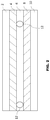
- FIG. 2 shows a cross section of part of a touch screen display
- FIGS. 3A to 3E show a set of views of a touchscreen display
- FIG. 4A to 4C show the expansion and retraction of graphical indicators
- FIG. 5 shows an example flowchart according to an embodiment
- a distance from a first touch point to a second contact point is determined when a user swipes a finger across a touch screen.
- An indication of the first touch point is visually rendered to give the user a reference point.
- a direction as given by a straight line (direct path) passing through the first and the second points is determined, sometimes for as long as the finger remains in contact with the touch screen.
- Dependent on the determined distance a number (e.g. 4) of graphical indicators are rendered and repositioned to indicate how far from the first touch point the finger has been swiped. The graphical indicators are rendered in-between the first touch point and the second contact point, along the determined direction.
- a first indicator is not rendered until a predetermined distance is attained from the first touch point.
- Each graphical indicator may be associated with a maximum distance from the first touch point at which they may be rendered. The determined distance and placement and/or the number of indicators are used to convey to the user speed and direction information which corresponds to the way in which the character is controlled to move on the screen.
- FIG. 1 A schematic view of a user or computing device 100 according to an embodiment is shown in FIG. 1 . All of the blocks shown illustrate a function or operation which can be implemented by suitable circuitry. The blocks may be implemented in hardware and/or software.
- the user device may have a control part 110 .
- the control part 110 has one or more processors 115 and one or more memories 120 .
- the processor(s) 115 executes game code stored in the memory 120 to perform the functions described herein.
- the control part 110 is also shown as having a graphics controller 125 and a sound controller 130 . It should be appreciated that one or other or both of the graphics controller 125 and sound controller 130 may be provided by the one or more processors 115 .
- the graphics controller 125 is configured to provide a video output 135 .
- the sound controller 130 is configured to provide an audio output 140 .
- the controller 110 has an interface 145 allowing the device to be able to communicate with a network such as the Internet or other communication infrastructure.
- the video output 135 is provided to a display 155 .
- the audio output 140 is provided to an audio device 160 such as a speaker and/or earphone(s).
- the device 100 has an input device 165 .
- the input device 165 is in the form of a touch sensitive device such as a touch screen. It should be appreciated that the display 155 may in some embodiments also provide the input device 165 by way of an integrated touch screen for example.
- the blocks of the controller 110 are configured to communicate with each other via an interconnect such as a bus or any other suitable interconnect and/or by point to point communication.
- an interconnect such as a bus or any other suitable interconnect and/or by point to point communication.
- controller 110 may be implemented by one or more integrated circuits, at least in part.
- the user device 100 is shown by way of example only. In alternative embodiments, one or more of the parts may be omitted. Alternatively or additionally, some embodiments may comprise one or more other parts. Alternatively or additionally, one or more parts may be combined.
- FIG. 2 schematically shows a touch screen.
- the touch screen may incorporate any suitable touch screen technology.
- One example of a touch screen technology is the so-called resistive touch screen technology.
- the front layer or surface 2 of the touch screen is typically made of a scratch-resistant, flexible plastic or similar.
- a thin film or coating 4 of conductive material is provided on the underside of the front surface.
- the film of conductive material can be of any suitable material and may for example be Indium Tin Oxide.
- a gap 6 is provided. This gap may be created by suitable spacers 12 . The gap may be an air gap.
- a second layer of material is provided. That layer may be of glass or hard plastic.
- the second layer 10 is also provided with a thin film or coating 8 of conductive material on the side of the second layer facing the spacing.
- the coating may be of any suitable material and may also be Indium Tin Oxide.
- the two layers 2 and 10 are kept apart by the spacers 12 which may be arranged at regular intervals.
- the thin conductive films or coatings are arranged to provide electrical resistance. The arrangement is such that the electrical charge runs in one direction on the one conductive coating or film and in a perpendicular direction on the other conductive coating
- the plastic With a resistive touch screen, when the screen is touched, the plastic deforms so that the two conductive films meet. By measuring the resistance of the two conductive films or coatings, the touch position can be accurately determined.
- touch screen Another technology often used for touch screens is capacitive technology.
- the structure of the touchscreen is similar to that described in relation to FIG. 2 .
- the first layer may typically be glass, and thus not flexible.
- the conductive coatings may be a uniform layer, a grid or parallel stripes running at right angles to each other on the two layers.
- a capacitive arrangement is formed by the two conductive coatings separated by the insulating material (air). When the finger comes close to a capacitor, it changes the local electrostatic field.
- the touchscreen effectively is made up of a large number of tiny capacitors. The system is arranged to monitor each of these tiny capacitors to determine where the finger touches the screen. Capacitive touch screens have the advantage that it is possible to determine several discrete touch points at the same time.
- Embodiments may be particularly applicable for games which are to be played on devices which have a relatively small screen, such as smart phones and some smaller tablets.
- a technical problem if a user has to contact a precise area on the small screen to implement an action, as the user's finger is relatively large relative to the screen.
- FIGS. 3A to e shows a first embodiment.
- Each of the arrangements shown in FIGS. 3A and 3E shows a view of a touchscreen display which is displaying a plurality of game objects.
- One of the game objects 26 is a user controlled entity.
- the user In order to move the user controlled entity 26 , the user will touch the touch screen at the location occupied by the user controlled entity and holding a finger against the touchscreen drag the user controlled entity to the new desired location.
- the user controlled entity may be moved by contacting the screen at any location (which may be separate from the location of the entity 26 ), and without lifting the finger from the screen, moving the finger to anywhere on the screen.
- the user controlled entity will move in the same direction between the point first touched on the screen (first touch point) and the new “drag”-position. That is, in a direction that extends from the first touch point to the new “drag”-position along a direct path.
- the move velocity of the user controlled entity is dependent on the distance between these points up to a maximum velocity.
- the user controlled entity continues to move until the user releases their finger from the screen.
- the user is able to control a character 26 on the game area shown on the display.
- the user places their finger anywhere on the screen (e.g. touch point 29 in FIG. 3C ) to ‘activate’ the character for some motion.
- each character is associated with a crescent shaped marker 28 underneath the character 26 pointed in the direction the character is currently facing.
- the user can touch the screen where the character is, or at another location spaced from the character.
- the character stops.
- the control of the character is directly responsive to the user's engagement with the screen.
- the described embodiments have user friendly character control features exemplified by graphical indicators as described in the following.
- the character 26 turns to “face” the direction of intended movement and starts to move at the speed and in the direction as determined by the distance in between, and the direction indicated by, the initial touch point 29 and the current position of the finger/contact point; and the first indicator 32 is shown, as shown for example in FIG. 3C .
- the second indicator 34 becomes visible and at a third and fourth distance from the initial contact point third and fourth indicators 36 , 38 are displayed respectively: see FIG. 3D for example.
- Each subsequent indicator is displayed at any one time in an animation which shows the indicator developing from the point at where the previous indicator was displayed, or conversely retracting towards the initial point of contact with respective increase and decrease of the distance from the initial touchpoint to the current point of contact.
- the user drags their finger along the screen creating a user input trace in the direction in which they wish the character to move. Note that this trace is detected by the circuitry of the touch screen, but is not made visible to a player. If the user only drags their finger a short distance, a small white circle 30 with a point (small arrowhead) in the direction of the drag appears (see FIG. 3B ). This is a first graphical marker in the form of a directional icon—it indicates a direction of movement intended by the user. Once they have dragged their finger beyond a minimum distance from the initial touch point, the first graphical indicator in the form of an arrow 32 appears.
- the minimum distance is along a first part of the user input trace, for as long as the user input trace is a straight line.
- a linear trace is calculated by the processor (as explained later) to determine a direct path between the first touch point and the new contact point, and the distance along that linear trace is used to determine the minimum distance.
- the second, third and fourth arrows consecutively appear, pointing in the direction the user dragged their finger in (or of the calculated linear trace).
- the number of arrows which appear depends upon the distance of the drag, up to a maximum of four arrows once a maximum distance is reached—the user has only dragged their finger a small distance in FIG.
- FIGS. 3A-3E so one arrow 32 has appeared, but the user has dragged up to or beyond the maximum distance in FIG. 3D causing four arrows to appear, 32 , 34 , 36 , 38 .
- the graphical markers described above are represented by arrowheads in FIGS. 3A-3E , but are not limited to this shape.
- the graphical indicators could instead take the shape of footsteps, dots or crosses. They may also not be limited to a maximum of four graphical indicators once the maximum distance of drag has been reached.
- the direction of the point on the crescent and the point on the circle move to follow, and the arrows move linearly, effectively as if user's first touch point on the screen is a pivot point for a straight line and the point at which finger is currently at is the tip of the line. It is possible to consider the direction and speed as an arrow (radial vector) extending outwards from a center of a circle (being the first touch point) to the radius of the circle (the second contact point). At each of certain radii from the centre the indicators are respectively rendered on the screen in a stepwise manner and once rendered, they are extended along the radial vector in a linear manner based on the determined distance of the finger from the initial point of contact.
- the indicators do not have to appear in a straight line arrangement in the direction of the character's travel. For example, they could appear like a pair of footprints, each foot appearing alternately, or in a pattern such as a wave, wherein the indicators are displaced at varying distances from either side of the arrow (radial vector) to give a wave pattern which ‘grows/shrinks’ in the direction of the arrow (radial vector).
- the aim of the user input is to control the movement of the character on the display.
- the direction of the arrows 32 , 34 , 36 , 38 determines the direction of motion of the character 26 , and the number of arrows determines the speed at which the character travels.
- the user drags further from the first point of contact, causing more arrows to appear until the maximum number of arrows is reached. See FIG. 4A , where intermediate renderings between, for example, indicators 32 and 34 are shown as 32 a , 34 a .
- the finger swipe is shown at 40 , in successive distances.
- the arrows retracting into/growing out from the one behind, shown in FIGS. 4A-4C is one example of a multitude of possible animations to show changes in the character's move velocity.
- the outermost graphical indicator could fade in/out, or slide behind/out of the previous indicator, or both.
- the animation could also match the type of indicator used. For example, in the case of footprint indicators, the indicators could appear as if footsteps were imprinting onto/growing out of the ground.
- the red bar above the character indicates their strength or health, which fluctuates depending on their performance in the game, against other characters and other game elements.
- a new finger touch starts the process over.
- a new initial point of contact is indicated and speed and direction are determined in relation to the new touch point.
- speed will increase and decrease depending on the direction in relation to the initial point of contact.
- FIG. 4C shows the effects on the graphical indicators when a user changes the direction of his finger swipe, e.g. 40 a causes the line of the indicator to move from position 30 through position 30 ′ to position 30 ′′, showing that the graphical indicators are repositioned along the new direct path.
- a small “dead zone” area (of a few pixels) around the initial touch position can be implemented, to avoid detecting unintended slight initial movements of the player's finger.
- the touch point may coincide with a specific pixel. However, in other embodiments, there may not be a one to one relationship between respective touch point and a respective pixel. That touch point may be determined by an algorithm in dependence on the signal output from the touch screen, for example to define coordinates with respect to the touch screen surface. When the user's finger stops moving, new coordinates can be detected for the new contact point and these coordinates may be used to determine whether the new contact point is outside a minimum distance from the touch point.
- the signal output is processed so as to define the contact point as the center point of the touch location. Defining a center of the touch location may make the determination of distance simpler.
- FIG. 5 shows a method of an embodiment.
- step S 1 the user touches the screen.
- this touch can take any suitable format and may comprise the user dragging their finger across the touchscreen in order to move the user controlled entity. It should be appreciated that the touch may be via a user's fingers or by using a stylus or the like. In some embodiments, the user will need to physically touch the touch screen in order to cause the interaction. In other embodiments, the user's interaction may need only to be in close proximity to the touchscreen in order to cause the interaction. It should be appreciated that the term “touch” is intended to cover any or all of these scenarios which result in a user input being detected by the touchscreen.
- step S 2 electrical signals will be generated by the touchscreen circuitry. This is as described for example in relation to FIG. 2 .
- the electrical signals provide information as to the location where the user has touched the touchscreen, (the user's first touch point) and latest contact point with the screen.
- the electrical signals are provided in step S 3 to a processing function.
- the processing function can be carried out by the code executed by the processers 115 .
- the signal processing function will analyze the signals to detect the user's intention to control the movement of the user controlled entity 26 .
- the processing function determines the location of the user's input.
- the location of the user's touch on the touch screen is determined from the received electronic signals from the touch screen, as known in the art. It should be appreciated that the processing function may also use stored information as to the entity or entities being displayed on the display at the location associated with the touch input.
- the user input is received continuously over a period of time.
- the location of the touch on the touchscreen changes and a determination is made about how fast and in what direction the user controlled character is to be moved. In some embodiments, this may be in conjunction with determining that the initial touch location is associated with a user controlled entity. Note that the direction of movement is also determined.
- step S 4 if it is determined that the user controlled entity is being moved, then the image of the user controlled entity which is displayed on the display moves along a direct path derived from (but not necessarily matching) the user's input traces as described above.
- the path of the movement and/or the location of the user controlled entity may be stored in memory.
- the location data of the user controlled entity may be updated in memory.
- appropriate graphical icons are rendered as described earlier, corresponding to the determined distance between touch and the direction of movement of the user's touch.
- Some embodiments may be implemented by at least one memory and at least one processor.
- the memory may be provided by memory circuitry and the processor may be provided by processor circuitry.
- Some embodiments may be provided by a computer program running on the at least one processor.
- the computer program may comprise computer implemented instructions which are stored in the at least one memory and which may be run on the at least one processor.
Landscapes
- Engineering & Computer Science (AREA)
- General Engineering & Computer Science (AREA)
- Theoretical Computer Science (AREA)
- Human Computer Interaction (AREA)
- Physics & Mathematics (AREA)
- General Physics & Mathematics (AREA)
- User Interface Of Digital Computer (AREA)
Abstract
Description
Claims (26)
Priority Applications (2)
| Application Number | Priority Date | Filing Date | Title |
|---|---|---|---|
| US15/161,739 US10949059B2 (en) | 2016-05-23 | 2016-05-23 | Controlling movement of an entity displayed on a user interface |
| PCT/EP2016/066204 WO2017009195A1 (en) | 2015-07-14 | 2016-07-07 | A method for capturing user input from a touch screen |
Applications Claiming Priority (1)
| Application Number | Priority Date | Filing Date | Title |
|---|---|---|---|
| US15/161,739 US10949059B2 (en) | 2016-05-23 | 2016-05-23 | Controlling movement of an entity displayed on a user interface |
Publications (2)
| Publication Number | Publication Date |
|---|---|
| US20170336905A1 US20170336905A1 (en) | 2017-11-23 |
| US10949059B2 true US10949059B2 (en) | 2021-03-16 |
Family
ID=60329157
Family Applications (1)
| Application Number | Title | Priority Date | Filing Date |
|---|---|---|---|
| US15/161,739 Active 2037-10-09 US10949059B2 (en) | 2015-07-14 | 2016-05-23 | Controlling movement of an entity displayed on a user interface |
Country Status (1)
| Country | Link |
|---|---|
| US (1) | US10949059B2 (en) |
Families Citing this family (4)
| Publication number | Priority date | Publication date | Assignee | Title |
|---|---|---|---|---|
| US10275691B2 (en) * | 2017-08-22 | 2019-04-30 | Northrop Grumman Systems Corporation | Adaptive real-time detection and examination network (ARDEN) |
| CN109491579B (en) * | 2017-09-12 | 2021-08-17 | 腾讯科技(深圳)有限公司 | Method and device for controlling virtual object |
| USD954067S1 (en) * | 2019-07-05 | 2022-06-07 | Bionime Corporation | Screen with graphical user interface |
| USD1063953S1 (en) * | 2019-08-23 | 2025-02-25 | Bionime Corporation | Screen with graphical user interface |
Citations (12)
| Publication number | Priority date | Publication date | Assignee | Title |
|---|---|---|---|---|
| US20070046647A1 (en) | 2005-08-30 | 2007-03-01 | Nintendo Co., Ltd. | Input data processing program and information processing apparatus |
| JP2011053101A (en) * | 2009-09-02 | 2011-03-17 | Tokai Rika Co Ltd | Vehicle present position display device and vehicle present position display method |
| EP2383027A2 (en) | 2010-04-28 | 2011-11-02 | Kabushiki Kaisha Square Enix (also trading as Square Enix Co., Ltd.) | User interface processing apparatus, method of processing user interface, and non-transitory computer-readable medium embodying computer program for processing user interface |
| US20130063380A1 (en) | 2011-09-08 | 2013-03-14 | Samsung Electronics Co., Ltd. | User interface for controlling release of a lock state in a terminal |
| US20140007019A1 (en) | 2012-06-29 | 2014-01-02 | Nokia Corporation | Method and apparatus for related user inputs |
| US20140038717A1 (en) | 2012-07-31 | 2014-02-06 | Konami Digital Entertainment Co., Ltd. | Game device, game system, game control method, and information storage medium |
| US20140221088A1 (en) | 2013-02-06 | 2014-08-07 | King-Com Limited | Computer game elements, systems, and methods therefor |
| US20150089366A1 (en) * | 2013-09-20 | 2015-03-26 | Oracle International Corporation | Temporal graph visualization |
| US20150094127A1 (en) | 2013-09-30 | 2015-04-02 | Zynga Inc. | Swipe-direction gesture control for video games using glass input devices |
| US20150258430A1 (en) * | 2014-03-12 | 2015-09-17 | Wargaming.Net Llp | User control of objects |
| US9772743B1 (en) * | 2015-03-30 | 2017-09-26 | Electronic Arts Inc. | Implementation of a movable control pad on a touch enabled device |
| US20170291110A1 (en) * | 2014-12-26 | 2017-10-12 | Cygames, Inc. | Game control program, game control method, and game control device |
-
2016
- 2016-05-23 US US15/161,739 patent/US10949059B2/en active Active
Patent Citations (12)
| Publication number | Priority date | Publication date | Assignee | Title |
|---|---|---|---|---|
| US20070046647A1 (en) | 2005-08-30 | 2007-03-01 | Nintendo Co., Ltd. | Input data processing program and information processing apparatus |
| JP2011053101A (en) * | 2009-09-02 | 2011-03-17 | Tokai Rika Co Ltd | Vehicle present position display device and vehicle present position display method |
| EP2383027A2 (en) | 2010-04-28 | 2011-11-02 | Kabushiki Kaisha Square Enix (also trading as Square Enix Co., Ltd.) | User interface processing apparatus, method of processing user interface, and non-transitory computer-readable medium embodying computer program for processing user interface |
| US20130063380A1 (en) | 2011-09-08 | 2013-03-14 | Samsung Electronics Co., Ltd. | User interface for controlling release of a lock state in a terminal |
| US20140007019A1 (en) | 2012-06-29 | 2014-01-02 | Nokia Corporation | Method and apparatus for related user inputs |
| US20140038717A1 (en) | 2012-07-31 | 2014-02-06 | Konami Digital Entertainment Co., Ltd. | Game device, game system, game control method, and information storage medium |
| US20140221088A1 (en) | 2013-02-06 | 2014-08-07 | King-Com Limited | Computer game elements, systems, and methods therefor |
| US20150089366A1 (en) * | 2013-09-20 | 2015-03-26 | Oracle International Corporation | Temporal graph visualization |
| US20150094127A1 (en) | 2013-09-30 | 2015-04-02 | Zynga Inc. | Swipe-direction gesture control for video games using glass input devices |
| US20150258430A1 (en) * | 2014-03-12 | 2015-09-17 | Wargaming.Net Llp | User control of objects |
| US20170291110A1 (en) * | 2014-12-26 | 2017-10-12 | Cygames, Inc. | Game control program, game control method, and game control device |
| US9772743B1 (en) * | 2015-03-30 | 2017-09-26 | Electronic Arts Inc. | Implementation of a movable control pad on a touch enabled device |
Non-Patent Citations (1)
| Title |
|---|
| Wireframe Tool, Principles of User Interface Design, Aug. 26, 2011, Wordpress.com, https://wireframetool.wordpress.com/2011/07/26/principles-of-user-interface-design/, pp. 1-2 (Year: 2011). * |
Also Published As
| Publication number | Publication date |
|---|---|
| US20170336905A1 (en) | 2017-11-23 |
Similar Documents
| Publication | Publication Date | Title |
|---|---|---|
| JP4295280B2 (en) | Method and apparatus for recognizing two-point user input with a touch-based user input device | |
| US20170371511A1 (en) | Speed/positional mode translations | |
| US9542005B2 (en) | Representative image | |
| US20090289902A1 (en) | Proximity sensor device and method with subregion based swipethrough data entry | |
| US20130155018A1 (en) | Device and method for emulating a touch screen using force information | |
| US20120120002A1 (en) | System and method for display proximity based control of a touch screen user interface | |
| US10620758B2 (en) | Glove touch detection | |
| US9262012B2 (en) | Hover angle | |
| US20090288889A1 (en) | Proximity sensor device and method with swipethrough data entry | |
| CN104049888A (en) | Electronic device and method for controlling screen display using temperature and humidity | |
| KR102719287B1 (en) | Method and apparatus for predicting touch location of electronic device | |
| US10949059B2 (en) | Controlling movement of an entity displayed on a user interface | |
| CN104346072A (en) | Display control apparatus and control method thereof | |
| KR101339420B1 (en) | Method and system for controlling contents in electronic book using bezel region | |
| TWI354223B (en) | ||
| CN105474164A (en) | Disambiguation of indirect input | |
| US9875020B2 (en) | Method for capturing user input from a touch screen and device having a touch screen | |
| CN113961106B (en) | Predictive control method, input system, and computer readable recording medium | |
| KR101333211B1 (en) | Method for controlling touch screen using bezel | |
| US20130249807A1 (en) | Method and apparatus for three-dimensional image rotation on a touch screen | |
| WO2017009195A1 (en) | A method for capturing user input from a touch screen | |
| JP2015203955A (en) | Drawing control device by digitizer pen, drawing control method and drawing control program | |
| CN110262747B (en) | Method and device for controlling terminal, terminal and storage medium | |
| US20150091831A1 (en) | Display device and display control method | |
| US11474625B1 (en) | Pressure gesture |
Legal Events
| Date | Code | Title | Description |
|---|---|---|---|
| AS | Assignment |
Owner name: KING.COM LTD., MALTA Free format text: ASSIGNMENT OF ASSIGNORS INTEREST;ASSIGNORS:PALAU, XAVIER;BALSACH, PERE;VAZQUEZ, DAMIA;AND OTHERS;REEL/FRAME:040255/0839 Effective date: 20160905 |
|
| STPP | Information on status: patent application and granting procedure in general |
Free format text: FINAL REJECTION MAILED |
|
| STPP | Information on status: patent application and granting procedure in general |
Free format text: DOCKETED NEW CASE - READY FOR EXAMINATION |
|
| STPP | Information on status: patent application and granting procedure in general |
Free format text: NON FINAL ACTION MAILED |
|
| STPP | Information on status: patent application and granting procedure in general |
Free format text: RESPONSE TO NON-FINAL OFFICE ACTION ENTERED AND FORWARDED TO EXAMINER |
|
| STPP | Information on status: patent application and granting procedure in general |
Free format text: NON FINAL ACTION MAILED |
|
| STPP | Information on status: patent application and granting procedure in general |
Free format text: RESPONSE TO NON-FINAL OFFICE ACTION ENTERED AND FORWARDED TO EXAMINER |
|
| STCF | Information on status: patent grant |
Free format text: PATENTED CASE |
|
| MAFP | Maintenance fee payment |
Free format text: PAYMENT OF MAINTENANCE FEE, 4TH YEAR, LARGE ENTITY (ORIGINAL EVENT CODE: M1551); ENTITY STATUS OF PATENT OWNER: LARGE ENTITY Year of fee payment: 4 |