US10944057B2 - Compound, material for organic electroluminescence devices, organic electroluminescence device, and electronic equipment - Google Patents
Compound, material for organic electroluminescence devices, organic electroluminescence device, and electronic equipment Download PDFInfo
- Publication number
- US10944057B2 US10944057B2 US14/909,930 US201514909930A US10944057B2 US 10944057 B2 US10944057 B2 US 10944057B2 US 201514909930 A US201514909930 A US 201514909930A US 10944057 B2 US10944057 B2 US 10944057B2
- Authority
- US
- United States
- Prior art keywords
- group
- compound
- formula
- substituted
- carbon atoms
- Prior art date
- Legal status (The legal status is an assumption and is not a legal conclusion. Google has not performed a legal analysis and makes no representation as to the accuracy of the status listed.)
- Active, expires
Links
- 0 C1=CC=C(C2(C3=CC=CC=C3)C3=C(C=CC=C3)C3=C2/C=C\C=C/3)C=C1.CC.CC.CC.CC.CC.CC.CC.CC.CC.CC.CC.CC.CC.CC.CCN(C[Ar])CC1=CC2=C(C=C1)C(C1=CC=CC=C1)(C1=CC=CC=C1)C1=C2C=CC=C1.CCN(C[Ar])CC1=CC=CC2=C1C1=C(C=CC=C1)C2(C1=CC=CC=C1)C1=CC=CC=C1.[9*]C1([10*])C2=C(C=CC=C2)C2=C1/C=C\C=C/2 Chemical compound C1=CC=C(C2(C3=CC=CC=C3)C3=C(C=CC=C3)C3=C2/C=C\C=C/3)C=C1.CC.CC.CC.CC.CC.CC.CC.CC.CC.CC.CC.CC.CC.CC.CCN(C[Ar])CC1=CC2=C(C=C1)C(C1=CC=CC=C1)(C1=CC=CC=C1)C1=C2C=CC=C1.CCN(C[Ar])CC1=CC=CC2=C1C1=C(C=CC=C1)C2(C1=CC=CC=C1)C1=CC=CC=C1.[9*]C1([10*])C2=C(C=CC=C2)C2=C1/C=C\C=C/2 0.000 description 35
- LZANUVOEISFZEA-UHFFFAOYSA-N C1=CC=C(C2=CC=C(C3=CC=C(N(C4=CC=C(C5=CC=C6C(=C5)C(C5=CC=CC=C5)(C5=CC=CC=C5)C5=C6C=CC=C5)C=C4)C4=CC5=C(C=C4)C(C4=CC=CC=C4)(C4=CC=CC=C4)C4=C5C=CC=C4)C=C3)C=C2)C=C1 Chemical compound C1=CC=C(C2=CC=C(C3=CC=C(N(C4=CC=C(C5=CC=C6C(=C5)C(C5=CC=CC=C5)(C5=CC=CC=C5)C5=C6C=CC=C5)C=C4)C4=CC5=C(C=C4)C(C4=CC=CC=C4)(C4=CC=CC=C4)C4=C5C=CC=C4)C=C3)C=C2)C=C1 LZANUVOEISFZEA-UHFFFAOYSA-N 0.000 description 4
- LAQGZGNRNBEMPV-UHFFFAOYSA-N C1=CC=C(C2(C3=CC=CC=C3)C3=CC(N(C4=CC5=C(C=C4)C4=CC=CC=C4C4=C5C=CC=C4)C4=CC=CC5=C4C4=C(C=CC=C4)C5(C4=CC=CC=C4)C4=CC=CC=C4)=CC=C3C3=C2C=CC=C3)C=C1.C1=CC=C(C2=CC=C(C3=CC=C(N(C4=CC=C5C(=C4)C(C4=CC=CC=C4)(C4=CC=CC=C4)C4=C5C=CC=C4)C4=CC=CC5=C4C4=C(C=CC=C4)C5(C4=CC=CC=C4)C4=CC=CC=C4)C=C3)C=C2)C=C1 Chemical compound C1=CC=C(C2(C3=CC=CC=C3)C3=CC(N(C4=CC5=C(C=C4)C4=CC=CC=C4C4=C5C=CC=C4)C4=CC=CC5=C4C4=C(C=CC=C4)C5(C4=CC=CC=C4)C4=CC=CC=C4)=CC=C3C3=C2C=CC=C3)C=C1.C1=CC=C(C2=CC=C(C3=CC=C(N(C4=CC=C5C(=C4)C(C4=CC=CC=C4)(C4=CC=CC=C4)C4=C5C=CC=C4)C4=CC=CC5=C4C4=C(C=CC=C4)C5(C4=CC=CC=C4)C4=CC=CC=C4)C=C3)C=C2)C=C1 LAQGZGNRNBEMPV-UHFFFAOYSA-N 0.000 description 3
- DZDLJNYMKVTZPE-UHFFFAOYSA-N C1=CC=C(C2(C3=CC=CC=C3)C3=CC(N(C4=CC=C(C5=CC6=C(C=C5)OC5=C6C=CC=C5)C=C4)C4=CC5=C(C=C4)C(C4=CC=CC=C4)(C4=CC=CC=C4)C4=C5C=CC=C4)=CC=C3C3=C2C=CC=C3)C=C1.C1=CC=C(C2(C3=CC=CC=C3)C3=CC(N(C4=CC=C(C5=CC=CC6=C5OC5=C6C=CC=C5)C=C4)C4=CC5=C(C=C4)C(C4=CC=CC=C4)(C4=CC=CC=C4)C4=C5C=CC=C4)=CC=C3C3=C2C=CC=C3)C=C1.C1=CC=C(C2(C3=CC=CC=C3)C3=CC(N(C4=CC=C5C(=C4)C(C4=CC=CC=C4)(C4=CC=CC=C4)C4=C5C=CC=C4)C4=CC5=C(C=C4)C(C4=CC=CC=C4)(C4=CC=CC=C4)C4=C5C=CC=C4)=CC=C3C3=C2C=CC=C3)C=C1 Chemical compound C1=CC=C(C2(C3=CC=CC=C3)C3=CC(N(C4=CC=C(C5=CC6=C(C=C5)OC5=C6C=CC=C5)C=C4)C4=CC5=C(C=C4)C(C4=CC=CC=C4)(C4=CC=CC=C4)C4=C5C=CC=C4)=CC=C3C3=C2C=CC=C3)C=C1.C1=CC=C(C2(C3=CC=CC=C3)C3=CC(N(C4=CC=C(C5=CC=CC6=C5OC5=C6C=CC=C5)C=C4)C4=CC5=C(C=C4)C(C4=CC=CC=C4)(C4=CC=CC=C4)C4=C5C=CC=C4)=CC=C3C3=C2C=CC=C3)C=C1.C1=CC=C(C2(C3=CC=CC=C3)C3=CC(N(C4=CC=C5C(=C4)C(C4=CC=CC=C4)(C4=CC=CC=C4)C4=C5C=CC=C4)C4=CC5=C(C=C4)C(C4=CC=CC=C4)(C4=CC=CC=C4)C4=C5C=CC=C4)=CC=C3C3=C2C=CC=C3)C=C1 DZDLJNYMKVTZPE-UHFFFAOYSA-N 0.000 description 3
- WAEFBOXJVMZOTN-UHFFFAOYSA-N C1=CC=C(C2(C3=CC=CC=C3)C3=CC(N(C4=CC=C(C5=CC6=C(C=C5)SC5=C6C=CC=C5)C=C4)C4=CC5=C(C=C4)C(C4=CC=CC=C4)(C4=CC=CC=C4)C4=C5C=CC=C4)=CC=C3C3=C2C=CC=C3)C=C1.C1=CC=C(C2(C3=CC=CC=C3)C3=CC(N(C4=CC=C(C5=CC=C(N6C7=C(C=CC=C7)C7=C6C=CC=C7)C=C5)C=C4)C4=CC5=C(C=C4)C(C4=CC=CC=C4)(C4=CC=CC=C4)C4=C5C=CC=C4)=CC=C3C3=C2C=CC=C3)C=C1.C1=CC=C(C2(C3=CC=CC=C3)C3=CC(N(C4=CC=C(C5=CC=CC6=C5SC5=C6C=CC=C5)C=C4)C4=CC5=C(C=C4)C(C4=CC=CC=C4)(C4=CC=CC=C4)C4=C5C=CC=C4)=CC=C3C3=C2C=CC=C3)C=C1 Chemical compound C1=CC=C(C2(C3=CC=CC=C3)C3=CC(N(C4=CC=C(C5=CC6=C(C=C5)SC5=C6C=CC=C5)C=C4)C4=CC5=C(C=C4)C(C4=CC=CC=C4)(C4=CC=CC=C4)C4=C5C=CC=C4)=CC=C3C3=C2C=CC=C3)C=C1.C1=CC=C(C2(C3=CC=CC=C3)C3=CC(N(C4=CC=C(C5=CC=C(N6C7=C(C=CC=C7)C7=C6C=CC=C7)C=C5)C=C4)C4=CC5=C(C=C4)C(C4=CC=CC=C4)(C4=CC=CC=C4)C4=C5C=CC=C4)=CC=C3C3=C2C=CC=C3)C=C1.C1=CC=C(C2(C3=CC=CC=C3)C3=CC(N(C4=CC=C(C5=CC=CC6=C5SC5=C6C=CC=C5)C=C4)C4=CC5=C(C=C4)C(C4=CC=CC=C4)(C4=CC=CC=C4)C4=C5C=CC=C4)=CC=C3C3=C2C=CC=C3)C=C1 WAEFBOXJVMZOTN-UHFFFAOYSA-N 0.000 description 3
- YKGNMXHGCVNVSH-UHFFFAOYSA-N C1=CC=C(C2(C3=CC=CC=C3)C3=CC(N(C4=CC=C(C5=CC=CC(N6C7=C(C=CC=C7)C7=C6C=CC=C7)=C5)C=C4)C4=CC5=C(C=C4)C(C4=CC=CC=C4)(C4=CC=CC=C4)C4=C5C=CC=C4)=CC=C3C3=C2C=CC=C3)C=C1.C1=CC=C(C2(C3=CC=CC=C3)C3=CC(N(C4=CC=C5C6=CC=CC=C6C6=CC=CC=C6C5=C4)C4=CC5=C(C=C4)C(C4=CC=CC=C4)(C4=CC=CC=C4)C4=C5C=CC=C4)=CC=C3C3=C2C=CC=C3)C=C1.C1=CC=C(C2=CC=C(C3=CC=C(N(C4=CC=C5C(=C4)C(C4=CC=CC=C4)(C4=CC=CC=C4)C4=C5C=CC=C4)C4=CC5=C(C=C4)C(C4=CC=CC=C4)(C4=CC=CC=C4)C4=C5C=CC=C4)C=C3)C=C2)C=C1 Chemical compound C1=CC=C(C2(C3=CC=CC=C3)C3=CC(N(C4=CC=C(C5=CC=CC(N6C7=C(C=CC=C7)C7=C6C=CC=C7)=C5)C=C4)C4=CC5=C(C=C4)C(C4=CC=CC=C4)(C4=CC=CC=C4)C4=C5C=CC=C4)=CC=C3C3=C2C=CC=C3)C=C1.C1=CC=C(C2(C3=CC=CC=C3)C3=CC(N(C4=CC=C5C6=CC=CC=C6C6=CC=CC=C6C5=C4)C4=CC5=C(C=C4)C(C4=CC=CC=C4)(C4=CC=CC=C4)C4=C5C=CC=C4)=CC=C3C3=C2C=CC=C3)C=C1.C1=CC=C(C2=CC=C(C3=CC=C(N(C4=CC=C5C(=C4)C(C4=CC=CC=C4)(C4=CC=CC=C4)C4=C5C=CC=C4)C4=CC5=C(C=C4)C(C4=CC=CC=C4)(C4=CC=CC=C4)C4=C5C=CC=C4)C=C3)C=C2)C=C1 YKGNMXHGCVNVSH-UHFFFAOYSA-N 0.000 description 3
- ALXCEAWHEVDVHS-UHFFFAOYSA-N BrC1=CC=C(C2=C/C3=C(\C=C/2)OC2=C3C=CC=C2)C=C1 Chemical compound BrC1=CC=C(C2=C/C3=C(\C=C/2)OC2=C3C=CC=C2)C=C1 ALXCEAWHEVDVHS-UHFFFAOYSA-N 0.000 description 2
- OGENPBMBOLTWLZ-UHFFFAOYSA-N BrC1=CC=C(C2=CC=C(N3C4=C(C=CC=C4)C4=C3C=CC=C4)C=C2)C=C1 Chemical compound BrC1=CC=C(C2=CC=C(N3C4=C(C=CC=C4)C4=C3C=CC=C4)C=C2)C=C1 OGENPBMBOLTWLZ-UHFFFAOYSA-N 0.000 description 2
- AOSMFTPKRRRYLA-UHFFFAOYSA-N BrC1=CC=C(C2=CC=CC(C3=CC=CC4=C3OC3=C4C=CC=C3)=C2)C=C1 Chemical compound BrC1=CC=C(C2=CC=CC(C3=CC=CC4=C3OC3=C4C=CC=C3)=C2)C=C1 AOSMFTPKRRRYLA-UHFFFAOYSA-N 0.000 description 2
- DCADYIVVLAPVLQ-UHFFFAOYSA-N C1=CC=C(C2(C3=CC=CC=C3)C3=CC(N(C4=CC5=C(C=C4)C4=C(C=CC=C4)C5(C4=CC=CC=C4)C4=CC=CC=C4)C4=CC=CC5=C4C4=C(C=CC=C4)C5(C4=CC=CC=C4)C4=CC=CC=C4)=CC=C3C3=C2C=CC=C3)C=C1.C1=CC=C(C2=CC=C(N(C3=CC4=C(C=C3)C3=C(C=CC=C3)C4(C3=CC=CC=C3)C3=CC=CC=C3)C3=CC=CC4=C3C3=C(C=CC=C3)C4(C3=CC=CC=C3)C3=CC=CC=C3)C=C2)C=C1.C1=CC=C(C2=CC=CC=C2N(C2=CC3=C(C=C2)C2=C(C=CC=C2)C3(C2=CC=CC=C2)C2=CC=CC=C2)C2=CC=CC3=C2C2=C(C=CC=C2)C3(C2=CC=CC=C2)C2=CC=CC=C2)C=C1 Chemical compound C1=CC=C(C2(C3=CC=CC=C3)C3=CC(N(C4=CC5=C(C=C4)C4=C(C=CC=C4)C5(C4=CC=CC=C4)C4=CC=CC=C4)C4=CC=CC5=C4C4=C(C=CC=C4)C5(C4=CC=CC=C4)C4=CC=CC=C4)=CC=C3C3=C2C=CC=C3)C=C1.C1=CC=C(C2=CC=C(N(C3=CC4=C(C=C3)C3=C(C=CC=C3)C4(C3=CC=CC=C3)C3=CC=CC=C3)C3=CC=CC4=C3C3=C(C=CC=C3)C4(C3=CC=CC=C3)C3=CC=CC=C3)C=C2)C=C1.C1=CC=C(C2=CC=CC=C2N(C2=CC3=C(C=C2)C2=C(C=CC=C2)C3(C2=CC=CC=C2)C2=CC=CC=C2)C2=CC=CC3=C2C2=C(C=CC=C2)C3(C2=CC=CC=C2)C2=CC=CC=C2)C=C1 DCADYIVVLAPVLQ-UHFFFAOYSA-N 0.000 description 2
- YJAKYDNKAFNUMD-UHFFFAOYSA-N C1=CC=C(C2(C3=CC=CC=C3)C3=CC(N(C4=CC5=C(C=C4)C4=CC=CC=C4C4=C5C=CC=C4)C4=CC=CC5=C4C4=C(C=CC=C4)C5(C4=CC=CC=C4)C4=CC=CC=C4)=CC=C3C3=C2C=CC=C3)C=C1 Chemical compound C1=CC=C(C2(C3=CC=CC=C3)C3=CC(N(C4=CC5=C(C=C4)C4=CC=CC=C4C4=C5C=CC=C4)C4=CC=CC5=C4C4=C(C=CC=C4)C5(C4=CC=CC=C4)C4=CC=CC=C4)=CC=C3C3=C2C=CC=C3)C=C1 YJAKYDNKAFNUMD-UHFFFAOYSA-N 0.000 description 2
- CPHXLVRJHAQRBM-UHFFFAOYSA-N C1=CC=C(C2(C3=CC=CC=C3)C3=CC(N(C4=CC=C(C5=CC6=C(C=C5)C(C5=CC=CC=C5)(C5=CC=CC=C5)C5=C6C=CC=C5)C=C4)C4=CC=C5C(=C4)C(C4=CC=CC=C4)(C4=CC=CC=C4)C4=C5C=CC=C4)=CC=C3C3=C2C=CC=C3)C=C1.C1=CC=C(C2=CC=C(N(C3=CC=C(C4=CC5=C(C=C4)C(C4=CC=CC=C4)(C4=CC=CC=C4)C4=C5C=CC=C4)C=C3)C3=CC=C4C(=C3)C(C3=CC=CC=C3)(C3=CC=CC=C3)C3=C4C=CC=C3)C=C2)C=C1.C1=CC=C(C2=CC=CC=C2N(C2=CC=C(C3=CC4=C(C=C3)C(C3=CC=CC=C3)(C3=CC=CC=C3)C3=C4C=CC=C3)C=C2)C2=CC=C3C(=C2)C(C2=CC=CC=C2)(C2=CC=CC=C2)C2=C3C=CC=C2)C=C1.CC1(C)C2=CC(N(C3=CC=C(C4=CC5=C(C=C4)C(C4=CC=CC=C4)(C4=CC=CC=C4)C4=C5C=CC=C4)C=C3)C3=CC=C4C(=C3)C(C3=CC=CC=C3)(C3=CC=CC=C3)C3=C4C=CC=C3)=CC=C2C2=C1C=CC=C2 Chemical compound C1=CC=C(C2(C3=CC=CC=C3)C3=CC(N(C4=CC=C(C5=CC6=C(C=C5)C(C5=CC=CC=C5)(C5=CC=CC=C5)C5=C6C=CC=C5)C=C4)C4=CC=C5C(=C4)C(C4=CC=CC=C4)(C4=CC=CC=C4)C4=C5C=CC=C4)=CC=C3C3=C2C=CC=C3)C=C1.C1=CC=C(C2=CC=C(N(C3=CC=C(C4=CC5=C(C=C4)C(C4=CC=CC=C4)(C4=CC=CC=C4)C4=C5C=CC=C4)C=C3)C3=CC=C4C(=C3)C(C3=CC=CC=C3)(C3=CC=CC=C3)C3=C4C=CC=C3)C=C2)C=C1.C1=CC=C(C2=CC=CC=C2N(C2=CC=C(C3=CC4=C(C=C3)C(C3=CC=CC=C3)(C3=CC=CC=C3)C3=C4C=CC=C3)C=C2)C2=CC=C3C(=C2)C(C2=CC=CC=C2)(C2=CC=CC=C2)C2=C3C=CC=C2)C=C1.CC1(C)C2=CC(N(C3=CC=C(C4=CC5=C(C=C4)C(C4=CC=CC=C4)(C4=CC=CC=C4)C4=C5C=CC=C4)C=C3)C3=CC=C4C(=C3)C(C3=CC=CC=C3)(C3=CC=CC=C3)C3=C4C=CC=C3)=CC=C2C2=C1C=CC=C2 CPHXLVRJHAQRBM-UHFFFAOYSA-N 0.000 description 2
- ZNBUJEGCIRHGIB-UHFFFAOYSA-N C1=CC=C(C2(C3=CC=CC=C3)C3=CC(N(C4=CC=C(C5=CC6=C(C=C5)SC5=C6C=CC=C5)C=C4)C4=CC5=C(C=C4)C(C4=CC=CC=C4)(C4=CC=CC=C4)C4=C5C=CC=C4)=CC=C3C3=C2C=CC=C3)C=C1 Chemical compound C1=CC=C(C2(C3=CC=CC=C3)C3=CC(N(C4=CC=C(C5=CC6=C(C=C5)SC5=C6C=CC=C5)C=C4)C4=CC5=C(C=C4)C(C4=CC=CC=C4)(C4=CC=CC=C4)C4=C5C=CC=C4)=CC=C3C3=C2C=CC=C3)C=C1 ZNBUJEGCIRHGIB-UHFFFAOYSA-N 0.000 description 2
- HTKMTWSNOHGYNK-UHFFFAOYSA-N C1=CC=C(C2(C3=CC=CC=C3)C3=CC(N(C4=CC=C(C5=CC=C(N6C7=C(C=CC=C7)C7=C6C=CC=C7)C=C5)C=C4)C4=CC=CC5=C4C4=C(C=CC=C4)C5(C4=CC=CC=C4)C4=CC=CC=C4)=CC=C3C3=C2C=CC=C3)C=C1.C1=CC=C(C2(C3=CC=CC=C3)C3=CC(N(C4=CC=C(C5=CC=C6SC7=C(C=CC=C7)C6=C5)C=C4)C4=CC=CC5=C4C4=C(C=CC=C4)C5(C4=CC=CC=C4)C4=CC=CC=C4)=CC=C3C3=C2C=CC=C3)C=C1 Chemical compound C1=CC=C(C2(C3=CC=CC=C3)C3=CC(N(C4=CC=C(C5=CC=C(N6C7=C(C=CC=C7)C7=C6C=CC=C7)C=C5)C=C4)C4=CC=CC5=C4C4=C(C=CC=C4)C5(C4=CC=CC=C4)C4=CC=CC=C4)=CC=C3C3=C2C=CC=C3)C=C1.C1=CC=C(C2(C3=CC=CC=C3)C3=CC(N(C4=CC=C(C5=CC=C6SC7=C(C=CC=C7)C6=C5)C=C4)C4=CC=CC5=C4C4=C(C=CC=C4)C5(C4=CC=CC=C4)C4=CC=CC=C4)=CC=C3C3=C2C=CC=C3)C=C1 HTKMTWSNOHGYNK-UHFFFAOYSA-N 0.000 description 2
- HENUSRZUBGUEDE-UHFFFAOYSA-N C1=CC=C(C2(C3=CC=CC=C3)C3=CC(N(C4=CC=C(C5=CC=C6OC7=C(C=CC=C7)C6=C5)C=C4)C4=CC=CC5=C4C4=C(C=CC=C4)C5(C4=CC=CC=C4)C4=CC=CC=C4)=CC=C3C3=C2C=CC=C3)C=C1.C1=CC=C(C2(C3=CC=CC=C3)C3=CC(N(C4=CC=C(C5=CC=CC6=C5OC5=C6C=CC=C5)C=C4)C4=CC=CC5=C4C4=C(C=CC=C4)C5(C4=CC=CC=C4)C4=CC=CC=C4)=CC=C3C3=C2C=CC=C3)C=C1.C1=CC=C(C2(C3=CC=CC=C3)C3=CC(N(C4=CC=C(C5=CC=CC6=C5SC5=C6C=CC=C5)C=C4)C4=CC=CC5=C4C4=C(C=CC=C4)C5(C4=CC=CC=C4)C4=CC=CC=C4)=CC=C3C3=C2C=CC=C3)C=C1 Chemical compound C1=CC=C(C2(C3=CC=CC=C3)C3=CC(N(C4=CC=C(C5=CC=C6OC7=C(C=CC=C7)C6=C5)C=C4)C4=CC=CC5=C4C4=C(C=CC=C4)C5(C4=CC=CC=C4)C4=CC=CC=C4)=CC=C3C3=C2C=CC=C3)C=C1.C1=CC=C(C2(C3=CC=CC=C3)C3=CC(N(C4=CC=C(C5=CC=CC6=C5OC5=C6C=CC=C5)C=C4)C4=CC=CC5=C4C4=C(C=CC=C4)C5(C4=CC=CC=C4)C4=CC=CC=C4)=CC=C3C3=C2C=CC=C3)C=C1.C1=CC=C(C2(C3=CC=CC=C3)C3=CC(N(C4=CC=C(C5=CC=CC6=C5SC5=C6C=CC=C5)C=C4)C4=CC=CC5=C4C4=C(C=CC=C4)C5(C4=CC=CC=C4)C4=CC=CC=C4)=CC=C3C3=C2C=CC=C3)C=C1 HENUSRZUBGUEDE-UHFFFAOYSA-N 0.000 description 2
- UPJMVUIDXPPDRM-UHFFFAOYSA-N C1=CC=C(C2(C3=CC=CC=C3)C3=CC(N(C4=CC=C(C5=CC=CC(/C6=C/C=C\C7=C6OC6=C7C=CC=C6)=C5)C=C4)C4=CC=CC5=C4C4=C(C=CC=C4)C5(C4=CC=CC=C4)C4=CC=CC=C4)=CC=C3C3=C2C=CC=C3)C=C1.C1=CC=C(C2(C3=CC=CC=C3)C3=CC(N(C4=CC=C(C5=CC=CC(N6C7=C(C=CC=C7)C7=C6C=CC=C7)=C5)C=C4)C4=CC=CC5=C4C4=C(C=CC=C4)C5(C4=CC=CC=C4)C4=CC=CC=C4)=CC=C3C3=C2C=CC=C3)C=C1 Chemical compound C1=CC=C(C2(C3=CC=CC=C3)C3=CC(N(C4=CC=C(C5=CC=CC(/C6=C/C=C\C7=C6OC6=C7C=CC=C6)=C5)C=C4)C4=CC=CC5=C4C4=C(C=CC=C4)C5(C4=CC=CC=C4)C4=CC=CC=C4)=CC=C3C3=C2C=CC=C3)C=C1.C1=CC=C(C2(C3=CC=CC=C3)C3=CC(N(C4=CC=C(C5=CC=CC(N6C7=C(C=CC=C7)C7=C6C=CC=C7)=C5)C=C4)C4=CC=CC5=C4C4=C(C=CC=C4)C5(C4=CC=CC=C4)C4=CC=CC=C4)=CC=C3C3=C2C=CC=C3)C=C1 UPJMVUIDXPPDRM-UHFFFAOYSA-N 0.000 description 2
- NQFPRESDTSNREG-UHFFFAOYSA-N C1=CC=C(C2(C3=CC=CC=C3)C3=CC(N(C4=CC=C(C5=CC=CC(C6=CC=CC7=C6OC6=C7C=CC=C6)=C5)C=C4)C4=CC5=C(C=C4)C(C4=CC=CC=C4)(C4=CC=CC=C4)C4=C5C=CC=C4)=CC=C3C3=C2C=CC=C3)C=C1 Chemical compound C1=CC=C(C2(C3=CC=CC=C3)C3=CC(N(C4=CC=C(C5=CC=CC(C6=CC=CC7=C6OC6=C7C=CC=C6)=C5)C=C4)C4=CC5=C(C=C4)C(C4=CC=CC=C4)(C4=CC=CC=C4)C4=C5C=CC=C4)=CC=C3C3=C2C=CC=C3)C=C1 NQFPRESDTSNREG-UHFFFAOYSA-N 0.000 description 2
- AXJPCSIGEWMREZ-UHFFFAOYSA-N C1=CC=C(C2(C3=CC=CC=C3)C3=CC(N(C4=CC=C(C5=CC=CC(C6=CC=CC7=C6OC6=C7C=CC=C6)=C5)C=C4)C4=CC5=C(C=C4)C(C4=CC=CC=C4)(C4=CC=CC=C4)C4=C5C=CC=C4)=CC=C3C3=C2C=CC=C3)C=C1.C1=CC=C(C2=C(N(C3=CC=C(C4=CC=C5C(=C4)C(C4=CC=CC=C4)(C4=CC=CC=C4)C4=C5C=CC=C4)C=C3)C3=CC4=C(C=C3)C(C3=CC=CC=C3)(C3=CC=CC=C3)C3=C4C=CC=C3)C=CC=C2)C=C1.C1=CC=C(C2=CC=C(N(C3=CC=C(C4=CC=C5C(=C4)C(C4=CC=CC=C4)(C4=CC=CC=C4)C4=C5C=CC=C4)C=C3)C3=CC4=C(C=C3)C(C3=CC=CC=C3)(C3=CC=CC=C3)C3=C4C=CC=C3)C=C2)C=C1 Chemical compound C1=CC=C(C2(C3=CC=CC=C3)C3=CC(N(C4=CC=C(C5=CC=CC(C6=CC=CC7=C6OC6=C7C=CC=C6)=C5)C=C4)C4=CC5=C(C=C4)C(C4=CC=CC=C4)(C4=CC=CC=C4)C4=C5C=CC=C4)=CC=C3C3=C2C=CC=C3)C=C1.C1=CC=C(C2=C(N(C3=CC=C(C4=CC=C5C(=C4)C(C4=CC=CC=C4)(C4=CC=CC=C4)C4=C5C=CC=C4)C=C3)C3=CC4=C(C=C3)C(C3=CC=CC=C3)(C3=CC=CC=C3)C3=C4C=CC=C3)C=CC=C2)C=C1.C1=CC=C(C2=CC=C(N(C3=CC=C(C4=CC=C5C(=C4)C(C4=CC=CC=C4)(C4=CC=CC=C4)C4=C5C=CC=C4)C=C3)C3=CC4=C(C=C3)C(C3=CC=CC=C3)(C3=CC=CC=C3)C3=C4C=CC=C3)C=C2)C=C1 AXJPCSIGEWMREZ-UHFFFAOYSA-N 0.000 description 2
- UEHOGBDVCKZIPE-UHFFFAOYSA-N C1=CC=C(C2(C3=CC=CC=C3)C3=CC(N(C4=CC=C(C5=CC=CC6=C5C5=C(C=CC=C5)C6(C5=CC=CC=C5)C5=CC=CC=C5)C=C4)C4=CC=C5C(=C4)C(C4=CC=CC=C4)(C4=CC=CC=C4)C4=C5C=CC=C4)=CC=C3C3=C2C=CC=C3)C=C1.C1=CC=C(C2=CC=C(N(C3=CC=C(C4=CC=CC5=C4C4=C(C=CC=C4)C5(C4=CC=CC=C4)C4=CC=CC=C4)C=C3)C3=CC=C4C(=C3)C(C3=CC=CC=C3)(C3=CC=CC=C3)C3=C4C=CC=C3)C=C2)C=C1.C1=CC=C(C2=CC=CC=C2N(C2=CC=C(C3=CC=CC4=C3C3=C(C=CC=C3)C4(C3=CC=CC=C3)C3=CC=CC=C3)C=C2)C2=CC=C3C(=C2)C(C2=CC=CC=C2)(C2=CC=CC=C2)C2=C3C=CC=C2)C=C1 Chemical compound C1=CC=C(C2(C3=CC=CC=C3)C3=CC(N(C4=CC=C(C5=CC=CC6=C5C5=C(C=CC=C5)C6(C5=CC=CC=C5)C5=CC=CC=C5)C=C4)C4=CC=C5C(=C4)C(C4=CC=CC=C4)(C4=CC=CC=C4)C4=C5C=CC=C4)=CC=C3C3=C2C=CC=C3)C=C1.C1=CC=C(C2=CC=C(N(C3=CC=C(C4=CC=CC5=C4C4=C(C=CC=C4)C5(C4=CC=CC=C4)C4=CC=CC=C4)C=C3)C3=CC=C4C(=C3)C(C3=CC=CC=C3)(C3=CC=CC=C3)C3=C4C=CC=C3)C=C2)C=C1.C1=CC=C(C2=CC=CC=C2N(C2=CC=C(C3=CC=CC4=C3C3=C(C=CC=C3)C4(C3=CC=CC=C3)C3=CC=CC=C3)C=C2)C2=CC=C3C(=C2)C(C2=CC=CC=C2)(C2=CC=CC=C2)C2=C3C=CC=C2)C=C1 UEHOGBDVCKZIPE-UHFFFAOYSA-N 0.000 description 2
- JDKKELSKUSWJEV-UHFFFAOYSA-N C1=CC=C(C2(C3=CC=CC=C3)C3=CC(N(C4=CC=C5C6=CC=CC=C6C6=CC=CC=C6C5=C4)C4=CC5=C(C=C4)C(C4=CC=CC=C4)(C4=CC=CC=C4)C4=C5C=CC=C4)=CC=C3C3=C2C=CC=C3)C=C1 Chemical compound C1=CC=C(C2(C3=CC=CC=C3)C3=CC(N(C4=CC=C5C6=CC=CC=C6C6=CC=CC=C6C5=C4)C4=CC5=C(C=C4)C(C4=CC=CC=C4)(C4=CC=CC=C4)C4=C5C=CC=C4)=CC=C3C3=C2C=CC=C3)C=C1 JDKKELSKUSWJEV-UHFFFAOYSA-N 0.000 description 2
- IILNYGKLLIUPGL-UHFFFAOYSA-N C1=CC=C(C2=C(N(C3=CC=C(C4=CC=C5C(=C4)C(C4=CC=CC=C4)(C4=CC=CC=C4)C4=C5C=CC=C4)C=C3)C3=CC4=C(C=C3)C(C3=CC=CC=C3)(C3=CC=CC=C3)C3=C4C=CC=C3)C=CC=C2)C=C1 Chemical compound C1=CC=C(C2=C(N(C3=CC=C(C4=CC=C5C(=C4)C(C4=CC=CC=C4)(C4=CC=CC=C4)C4=C5C=CC=C4)C=C3)C3=CC4=C(C=C3)C(C3=CC=CC=C3)(C3=CC=CC=C3)C3=C4C=CC=C3)C=CC=C2)C=C1 IILNYGKLLIUPGL-UHFFFAOYSA-N 0.000 description 2
- JJHSOFPCWLJBPZ-UHFFFAOYSA-N C1=CC=C(C2=CC=C(C3=CC=C(N(C4=CC=C(C5=CC=C6C(=C5)C(C5=CC=CC=C5)(C5=CC=CC=C5)C5=C6C=CC=C5)C=C4)C4=CC=CC5=C4C4=C(C=CC=C4)C5(C4=CC=CC=C4)C4=CC=CC=C4)C=C3)C=C2)C=C1.C1=CC=C(C2=CC=C(N(C3=CC=C(C4=CC=C5C(=C4)C(C4=CC=CC=C4)(C4=CC=CC=C4)C4=C5C=CC=C4)C=C3)C3=CC=CC4=C3C3=C(C=CC=C3)C4(C3=CC=CC=C3)C3=CC=CC=C3)C=C2)C=C1.C1=CC=C(C2=CC=CC=C2N(C2=CC=C(C3=CC=C4C(=C3)C(C3=CC=CC=C3)(C3=CC=CC=C3)C3=C4C=CC=C3)C=C2)C2=CC=CC3=C2C2=C(C=CC=C2)C3(C2=CC=CC=C2)C2=CC=CC=C2)C=C1 Chemical compound C1=CC=C(C2=CC=C(C3=CC=C(N(C4=CC=C(C5=CC=C6C(=C5)C(C5=CC=CC=C5)(C5=CC=CC=C5)C5=C6C=CC=C5)C=C4)C4=CC=CC5=C4C4=C(C=CC=C4)C5(C4=CC=CC=C4)C4=CC=CC=C4)C=C3)C=C2)C=C1.C1=CC=C(C2=CC=C(N(C3=CC=C(C4=CC=C5C(=C4)C(C4=CC=CC=C4)(C4=CC=CC=C4)C4=C5C=CC=C4)C=C3)C3=CC=CC4=C3C3=C(C=CC=C3)C4(C3=CC=CC=C3)C3=CC=CC=C3)C=C2)C=C1.C1=CC=C(C2=CC=CC=C2N(C2=CC=C(C3=CC=C4C(=C3)C(C3=CC=CC=C3)(C3=CC=CC=C3)C3=C4C=CC=C3)C=C2)C2=CC=CC3=C2C2=C(C=CC=C2)C3(C2=CC=CC=C2)C2=CC=CC=C2)C=C1 JJHSOFPCWLJBPZ-UHFFFAOYSA-N 0.000 description 2
- VTSAYWZCLNPTGP-UHFFFAOYSA-N C1=CC=C(C2=CC=C(C3=CC=C(N(C4=CC=C(C5=CC=CC6=C5OC5=C6C=CC=C5)C=C4)C4=CC=C(C5=C6OC7=C(C=CC=C7)C6=CC=C5)C=C4)C=C3)C=C2)C=C1 Chemical compound C1=CC=C(C2=CC=C(C3=CC=C(N(C4=CC=C(C5=CC=CC6=C5OC5=C6C=CC=C5)C=C4)C4=CC=C(C5=C6OC7=C(C=CC=C7)C6=CC=C5)C=C4)C=C3)C=C2)C=C1 VTSAYWZCLNPTGP-UHFFFAOYSA-N 0.000 description 2
- WOLLHAZFMRKXJW-FRJZQVQDSA-N C1=CC=C(C2=CC=C(C3=CC=C(N(C4=CC=C(C5=CC=CC6=C5OC5=C6C=CC=C5)C=C4)C4=CC=C(C5=C6OC7=C(C=CC=C7)C6=CC=C5)C=C4)C=C3)C=C2)C=C1.[C-]#[N+]/C(C#N)=C1\C2=CC(C)=CC=C2C2=CC3=C(C=C21)/C(=C(/C#N)[N+]#[C-])C1=C3C=CC(OC(F)(F)F)=C1 Chemical compound C1=CC=C(C2=CC=C(C3=CC=C(N(C4=CC=C(C5=CC=CC6=C5OC5=C6C=CC=C5)C=C4)C4=CC=C(C5=C6OC7=C(C=CC=C7)C6=CC=C5)C=C4)C=C3)C=C2)C=C1.[C-]#[N+]/C(C#N)=C1\C2=CC(C)=CC=C2C2=CC3=C(C=C21)/C(=C(/C#N)[N+]#[C-])C1=C3C=CC(OC(F)(F)F)=C1 WOLLHAZFMRKXJW-FRJZQVQDSA-N 0.000 description 2
- LCDDTXVUUDEQJI-UHFFFAOYSA-N C1=CC=C(C2=CC=C(N(C3=CC=C4C(=C3)C(C3=CC=CC=C3)(C3=CC=CC=C3)C3=C4C=CC=C3)C3=CC4=C(C=C3)C(C3=CC=CC=C3)(C3=CC=CC=C3)C3=C4C=CC=C3)C=C2)C=C1.C1=CC=C(C2=CC=CC=C2N(C2=CC=C3C(=C2)C(C2=CC=CC=C2)(C2=CC=CC=C2)C2=C3C=CC=C2)C2=CC3=C(C=C2)C(C2=CC=CC=C2)(C2=CC=CC=C2)C2=C3C=CC=C2)C=C1.CC1(C)C2=CC(N(C3=CC=C4C(=C3)C(C3=CC=CC=C3)(C3=CC=CC=C3)C3=C4C=CC=C3)C3=CC4=C(C=C3)C(C3=CC=CC=C3)(C3=CC=CC=C3)C3=C4C=CC=C3)=CC=C2C2=C1C=CC=C2 Chemical compound C1=CC=C(C2=CC=C(N(C3=CC=C4C(=C3)C(C3=CC=CC=C3)(C3=CC=CC=C3)C3=C4C=CC=C3)C3=CC4=C(C=C3)C(C3=CC=CC=C3)(C3=CC=CC=C3)C3=C4C=CC=C3)C=C2)C=C1.C1=CC=C(C2=CC=CC=C2N(C2=CC=C3C(=C2)C(C2=CC=CC=C2)(C2=CC=CC=C2)C2=C3C=CC=C2)C2=CC3=C(C=C2)C(C2=CC=CC=C2)(C2=CC=CC=C2)C2=C3C=CC=C2)C=C1.CC1(C)C2=CC(N(C3=CC=C4C(=C3)C(C3=CC=CC=C3)(C3=CC=CC=C3)C3=C4C=CC=C3)C3=CC4=C(C=C3)C(C3=CC=CC=C3)(C3=CC=CC=C3)C3=C4C=CC=C3)=CC=C2C2=C1C=CC=C2 LCDDTXVUUDEQJI-UHFFFAOYSA-N 0.000 description 2
- RUDYCBHYOGEWQC-UHFFFAOYSA-N C1=CC=C(C2=CC=CC=C2N(C2=CC=C(C3=CC=C4C(=C3)C(C3=CC=CC=C3)(C3=CC=CC=C3)C3=C4C=CC=C3)C=C2)C2=CC=CC3=C2C2=C(C=CC=C2)C3(C2=CC=CC=C2)C2=CC=CC=C2)C=C1 Chemical compound C1=CC=C(C2=CC=CC=C2N(C2=CC=C(C3=CC=C4C(=C3)C(C3=CC=CC=C3)(C3=CC=CC=C3)C3=C4C=CC=C3)C=C2)C2=CC=CC3=C2C2=C(C=CC=C2)C3(C2=CC=CC=C2)C2=CC=CC=C2)C=C1 RUDYCBHYOGEWQC-UHFFFAOYSA-N 0.000 description 2
- NRQKCZAXUUDXPZ-UHFFFAOYSA-N C1=CC=C(C2=CC=CC=C2N(C2=CC=C(C3=CC=CC4=C3C3=C(C=CC=C3)C4(C3=CC=CC=C3)C3=CC=CC=C3)C=C2)C2=CC=C3C(=C2)C(C2=CC=CC=C2)(C2=CC=CC=C2)C2=C3C=CC=C2)C=C1 Chemical compound C1=CC=C(C2=CC=CC=C2N(C2=CC=C(C3=CC=CC4=C3C3=C(C=CC=C3)C4(C3=CC=CC=C3)C3=CC=CC=C3)C=C2)C2=CC=C3C(=C2)C(C2=CC=CC=C2)(C2=CC=CC=C2)C2=C3C=CC=C2)C=C1 NRQKCZAXUUDXPZ-UHFFFAOYSA-N 0.000 description 2
- GMADXSLNDDSNIE-UHFFFAOYSA-N C1=CC=C(N2C3=C(C=CC=C3)C3=C2C=CC(C2=CC=C(C4=CC=C(N(C5=CC6=C(C=C5)C(C5=CC=CC=C5)(C5=CC=CC=C5)C5=C6C=CC=C5)C5=CC=CC6=C5C5=C(C=CC=C5)C6(C5=CC=CC=C5)C5=CC=CC=C5)C=C4)C=C2)=C3)C=C1.C1=CC=C(N2C3=C(C=CC=C3)C3=C2C=CC(C2=CC=C(C4=CC=C(N(C5=CC=C6C(=C5)C5=C(C=CC=C5)C6(C5=CC=CC=C5)C5=CC=CC=C5)C5=CC6=C(C=C5)C(C5=CC=CC=C5)(C5=CC=CC=C5)C5=C6C=CC=C5)C=C4)C=C2)=C3)C=C1.C1=CC=C(N2C3=C(C=CC=C3)C3=C2C=CC(C2=CC=C(N(C4=CC5=C(C=C4)C(C4=CC=CC=C4)(C4=CC=CC=C4)C4=C5C=CC=C4)C4=CC=CC5=C4C4=C(C=CC=C4)C5(C4=CC=CC=C4)C4=CC=CC=C4)C=C2)=C3)C=C1 Chemical compound C1=CC=C(N2C3=C(C=CC=C3)C3=C2C=CC(C2=CC=C(C4=CC=C(N(C5=CC6=C(C=C5)C(C5=CC=CC=C5)(C5=CC=CC=C5)C5=C6C=CC=C5)C5=CC=CC6=C5C5=C(C=CC=C5)C6(C5=CC=CC=C5)C5=CC=CC=C5)C=C4)C=C2)=C3)C=C1.C1=CC=C(N2C3=C(C=CC=C3)C3=C2C=CC(C2=CC=C(C4=CC=C(N(C5=CC=C6C(=C5)C5=C(C=CC=C5)C6(C5=CC=CC=C5)C5=CC=CC=C5)C5=CC6=C(C=C5)C(C5=CC=CC=C5)(C5=CC=CC=C5)C5=C6C=CC=C5)C=C4)C=C2)=C3)C=C1.C1=CC=C(N2C3=C(C=CC=C3)C3=C2C=CC(C2=CC=C(N(C4=CC5=C(C=C4)C(C4=CC=CC=C4)(C4=CC=CC=C4)C4=C5C=CC=C4)C4=CC=CC5=C4C4=C(C=CC=C4)C5(C4=CC=CC=C4)C4=CC=CC=C4)C=C2)=C3)C=C1 GMADXSLNDDSNIE-UHFFFAOYSA-N 0.000 description 2
- KHQLGOPHICSPCC-UHFFFAOYSA-N C1=CC=C(N2C3=C(C=CC=C3)C3=C2C=CC(C2=CC=C(C4=CC=C(N(C5=CC6=C(C=C5)C(C5=CC=CC=C5)(C5=CC=CC=C5)C5=C6C=CC=C5)C5=CC=CC6=C5C5=C(C=CC=C5)C65C6=C(C=CC=C6)C6=C5C=CC=C6)C=C4)C=C2)=C3)C=C1.C1=CC=C(N2C3=C(C=CC=C3)C3=C2C=CC(C2=CC=C(C4=CC=C(N(C5=CC=C6C(=C5)C5=C(C=CC=C5)C65C6=C(C=CC=C6)C6=C5C=CC=C6)C5=CC6=C(C=C5)C(C5=CC=CC=C5)(C5=CC=CC=C5)C5=C6C=CC=C5)C=C4)C=C2)=C3)C=C1.C1=CC=C(N2C3=C(C=CC=C3)C3=C2C=CC(C2=CC=C(N(C4=CC5=C(C=C4)C(C4=CC=CC=C4)(C4=CC=CC=C4)C4=C5C=CC=C4)C4=CC=CC5=C4C4=C(C=CC=C4)C54C5=C(C=CC=C5)C5=C4C=CC=C5)C=C2)=C3)C=C1 Chemical compound C1=CC=C(N2C3=C(C=CC=C3)C3=C2C=CC(C2=CC=C(C4=CC=C(N(C5=CC6=C(C=C5)C(C5=CC=CC=C5)(C5=CC=CC=C5)C5=C6C=CC=C5)C5=CC=CC6=C5C5=C(C=CC=C5)C65C6=C(C=CC=C6)C6=C5C=CC=C6)C=C4)C=C2)=C3)C=C1.C1=CC=C(N2C3=C(C=CC=C3)C3=C2C=CC(C2=CC=C(C4=CC=C(N(C5=CC=C6C(=C5)C5=C(C=CC=C5)C65C6=C(C=CC=C6)C6=C5C=CC=C6)C5=CC6=C(C=C5)C(C5=CC=CC=C5)(C5=CC=CC=C5)C5=C6C=CC=C5)C=C4)C=C2)=C3)C=C1.C1=CC=C(N2C3=C(C=CC=C3)C3=C2C=CC(C2=CC=C(N(C4=CC5=C(C=C4)C(C4=CC=CC=C4)(C4=CC=CC=C4)C4=C5C=CC=C4)C4=CC=CC5=C4C4=C(C=CC=C4)C54C5=C(C=CC=C5)C5=C4C=CC=C5)C=C2)=C3)C=C1 KHQLGOPHICSPCC-UHFFFAOYSA-N 0.000 description 2
- IUFQSBORCUJOLO-UHFFFAOYSA-N C1=CC=C(N2C3=C(C=CC=C3)C3=C2C=CC(C2=CC=C(C4=CC=C(N(C5=CC=C(C6=CC7=C(C=C6)C(C6=CC=CC=C6)(C6=CC=CC=C6)C6=C7C=CC=C6)C=C5)C5=CC=C6C(=C5)C(C5=CC=CC=C5)(C5=CC=CC=C5)C5=C6C=CC=C5)C=C4)C=C2)=C3)C=C1.C1=CC=C(N2C3=C(C=CC=C3)C3=C2C=CC(C2=CC=C(N(C4=CC=C(C5=CC6=C(C=C5)C(C5=CC=CC=C5)(C5=CC=CC=C5)C5=C6C=CC=C5)C=C4)C4=CC=C5C(=C4)C(C4=CC=CC=C4)(C4=CC=CC=C4)C4=C5C=CC=C4)C=C2)=C3)C=C1.C1=CC=C(N2C3=CC(C4=CC=C(C5=CC=C(N(C6=CC=C7C(=C6)C6(C8=C7C=CC=C8)C7=C(C=CC=C7)C7=C6C=CC=C7)C6=CC7=C(C=C6)C(C6=CC=CC=C6)(C6=CC=CC=C6)C6=C7C=CC=C6)C=C5)C=C4)=CC=C3C3=C2C=CC=C3)C=C1 Chemical compound C1=CC=C(N2C3=C(C=CC=C3)C3=C2C=CC(C2=CC=C(C4=CC=C(N(C5=CC=C(C6=CC7=C(C=C6)C(C6=CC=CC=C6)(C6=CC=CC=C6)C6=C7C=CC=C6)C=C5)C5=CC=C6C(=C5)C(C5=CC=CC=C5)(C5=CC=CC=C5)C5=C6C=CC=C5)C=C4)C=C2)=C3)C=C1.C1=CC=C(N2C3=C(C=CC=C3)C3=C2C=CC(C2=CC=C(N(C4=CC=C(C5=CC6=C(C=C5)C(C5=CC=CC=C5)(C5=CC=CC=C5)C5=C6C=CC=C5)C=C4)C4=CC=C5C(=C4)C(C4=CC=CC=C4)(C4=CC=CC=C4)C4=C5C=CC=C4)C=C2)=C3)C=C1.C1=CC=C(N2C3=CC(C4=CC=C(C5=CC=C(N(C6=CC=C7C(=C6)C6(C8=C7C=CC=C8)C7=C(C=CC=C7)C7=C6C=CC=C7)C6=CC7=C(C=C6)C(C6=CC=CC=C6)(C6=CC=CC=C6)C6=C7C=CC=C6)C=C5)C=C4)=CC=C3C3=C2C=CC=C3)C=C1 IUFQSBORCUJOLO-UHFFFAOYSA-N 0.000 description 2
- SKSNPKAJKQOXIZ-UHFFFAOYSA-N C1=CC=C(N2C3=C(C=CC=C3)C3=C2C=CC(C2=CC=C(C4=CC=C(N(C5=CC=C6C(=C5)C(C5=CC=CC=C5)(C5=CC=CC=C5)C5=C6C=CC=C5)C5=CC6=C(C=C5)C(C5=CC=CC=C5)(C5=CC=CC=C5)C5=C6C=CC=C5)C=C4)C=C2)=C3)C=C1.C1=CC=C(N2C3=C(C=CC=C3)C3=C2C=CC(C2=CC=C(N(C4=CC=C5C(=C4)C(C4=CC=CC=C4)(C4=CC=CC=C4)C4=C5C=CC=C4)C4=CC5=C(C=C4)C(C4=CC=CC=C4)(C4=CC=CC=C4)C4=C5C=CC=C4)C=C2)=C3)C=C1.C1=CC=C(N2C3=C(C=CC=C3)C3=C2C=CC(C2=CC=C(N(C4=CC=C5C(=C4)C4=C(C=CC=C4)C5(C4=CC=CC=C4)C4=CC=CC=C4)C4=CC5=C(C=C4)C(C4=CC=CC=C4)(C4=CC=CC=C4)C4=C5C=CC=C4)C=C2)=C3)C=C1 Chemical compound C1=CC=C(N2C3=C(C=CC=C3)C3=C2C=CC(C2=CC=C(C4=CC=C(N(C5=CC=C6C(=C5)C(C5=CC=CC=C5)(C5=CC=CC=C5)C5=C6C=CC=C5)C5=CC6=C(C=C5)C(C5=CC=CC=C5)(C5=CC=CC=C5)C5=C6C=CC=C5)C=C4)C=C2)=C3)C=C1.C1=CC=C(N2C3=C(C=CC=C3)C3=C2C=CC(C2=CC=C(N(C4=CC=C5C(=C4)C(C4=CC=CC=C4)(C4=CC=CC=C4)C4=C5C=CC=C4)C4=CC5=C(C=C4)C(C4=CC=CC=C4)(C4=CC=CC=C4)C4=C5C=CC=C4)C=C2)=C3)C=C1.C1=CC=C(N2C3=C(C=CC=C3)C3=C2C=CC(C2=CC=C(N(C4=CC=C5C(=C4)C4=C(C=CC=C4)C5(C4=CC=CC=C4)C4=CC=CC=C4)C4=CC5=C(C=C4)C(C4=CC=CC=C4)(C4=CC=CC=C4)C4=C5C=CC=C4)C=C2)=C3)C=C1 SKSNPKAJKQOXIZ-UHFFFAOYSA-N 0.000 description 2
- HZTCVKZYOXHGGI-UHFFFAOYSA-N C1=CC=C(N2C3=C(C=CC=C3)C3=C2C=CC(C2=CC=C(C4=CC=C(N(C5=CC=C6C(=C5)C5(C7=C6C=CC=C7)C6=C(C=CC=C6)C6=C5C=CC=C6)C5=CC6=C(C=C5)C(C5=CC=CC=C5)(C5=CC=CC=C5)C5=C6C=CC=C5)C=C4)C=C2)=C3)C=C1.C1=CC=C(N2C3=C(C=CC=C3)C3=C2C=CC(C2=CC=C(N(C4=CC=C5C(=C4)C4(C6=C5C=CC=C6)C5=C(C=CC=C5)C5=C4C=CC=C5)C4=CC5=C(C=C4)C(C4=CC=CC=C4)(C4=CC=CC=C4)C4=C5C=CC=C4)C=C2)=C3)C=C1.C1=CC=C(N2C3=C(C=CC=C3)C3=C2C=CC(C2=CC=C(N(C4=CC=C5C(=C4)C4=C(C=CC=C4)C54C5=C(C=CC=C5)C5=C4C=CC=C5)C4=CC5=C(C=C4)C(C4=CC=CC=C4)(C4=CC=CC=C4)C4=C5C=CC=C4)C=C2)=C3)C=C1 Chemical compound C1=CC=C(N2C3=C(C=CC=C3)C3=C2C=CC(C2=CC=C(C4=CC=C(N(C5=CC=C6C(=C5)C5(C7=C6C=CC=C7)C6=C(C=CC=C6)C6=C5C=CC=C6)C5=CC6=C(C=C5)C(C5=CC=CC=C5)(C5=CC=CC=C5)C5=C6C=CC=C5)C=C4)C=C2)=C3)C=C1.C1=CC=C(N2C3=C(C=CC=C3)C3=C2C=CC(C2=CC=C(N(C4=CC=C5C(=C4)C4(C6=C5C=CC=C6)C5=C(C=CC=C5)C5=C4C=CC=C5)C4=CC5=C(C=C4)C(C4=CC=CC=C4)(C4=CC=CC=C4)C4=C5C=CC=C4)C=C2)=C3)C=C1.C1=CC=C(N2C3=C(C=CC=C3)C3=C2C=CC(C2=CC=C(N(C4=CC=C5C(=C4)C4=C(C=CC=C4)C54C5=C(C=CC=C5)C5=C4C=CC=C5)C4=CC5=C(C=C4)C(C4=CC=CC=C4)(C4=CC=CC=C4)C4=C5C=CC=C4)C=C2)=C3)C=C1 HZTCVKZYOXHGGI-UHFFFAOYSA-N 0.000 description 2
- YLXWIZXBGMINAM-UHFFFAOYSA-N C1=CC=C(N2C3=CC(C4=CC=C(C5=CC=C(N(C6=CC=C7C(=C6)C(C6=CC=CC=C6)(C6=CC=CC=C6)C6=C7C=CC=C6)C6=CC7=C(C=C6)C(C6=CC=CC=C6)(C6=CC=CC=C6)C6=C7C=CC=C6)C=C5)C=C4)=CC=C3C3=C2C=CC=C3)C=C1.C1=CC=C(N2C3=CC(C4=CC=C(N(C5=CC=C6C(=C5)C(C5=CC=CC=C5)(C5=CC=CC=C5)C5=C6C=CC=C5)C5=CC6=C(C=C5)C(C5=CC=CC=C5)(C5=CC=CC=C5)C5=C6C=CC=C5)C=C4)=CC=C3C3=C2C=CC=C3)C=C1.C1=CC=C(N2C3=CC(C4=CC=C(N(C5=CC=C6C(=C5)C5(C7=C6C=CC=C7)C6=C(C=CC=C6)C6=C5C=CC=C6)C5=CC6=C(C=C5)C(C5=CC=CC=C5)(C5=CC=CC=C5)C5=C6C=CC=C5)C=C4)=CC=C3C3=C2C=CC=C3)C=C1 Chemical compound C1=CC=C(N2C3=CC(C4=CC=C(C5=CC=C(N(C6=CC=C7C(=C6)C(C6=CC=CC=C6)(C6=CC=CC=C6)C6=C7C=CC=C6)C6=CC7=C(C=C6)C(C6=CC=CC=C6)(C6=CC=CC=C6)C6=C7C=CC=C6)C=C5)C=C4)=CC=C3C3=C2C=CC=C3)C=C1.C1=CC=C(N2C3=CC(C4=CC=C(N(C5=CC=C6C(=C5)C(C5=CC=CC=C5)(C5=CC=CC=C5)C5=C6C=CC=C5)C5=CC6=C(C=C5)C(C5=CC=CC=C5)(C5=CC=CC=C5)C5=C6C=CC=C5)C=C4)=CC=C3C3=C2C=CC=C3)C=C1.C1=CC=C(N2C3=CC(C4=CC=C(N(C5=CC=C6C(=C5)C5(C7=C6C=CC=C7)C6=C(C=CC=C6)C6=C5C=CC=C6)C5=CC6=C(C=C5)C(C5=CC=CC=C5)(C5=CC=CC=C5)C5=C6C=CC=C5)C=C4)=CC=C3C3=C2C=CC=C3)C=C1 YLXWIZXBGMINAM-UHFFFAOYSA-N 0.000 description 2
- CNKZONHRXVCFOF-UHFFFAOYSA-N CC.CC.CC.CC.CC.CC.CC.CC.[Ar]CN(C1=CC=CC2=C1C1=C(C=CC=C1)C2(C1=CC=CC=C1)C1=CC=CC=C1)C1=C/C2=C(\C=C/1)C1=C(C=CC=C1)C2(C1=CC=CC=C1)C1=CC=CC=C1 Chemical compound CC.CC.CC.CC.CC.CC.CC.CC.[Ar]CN(C1=CC=CC2=C1C1=C(C=CC=C1)C2(C1=CC=CC=C1)C1=CC=CC=C1)C1=C/C2=C(\C=C/1)C1=C(C=CC=C1)C2(C1=CC=CC=C1)C1=CC=CC=C1 CNKZONHRXVCFOF-UHFFFAOYSA-N 0.000 description 2
- VOWZNWHOISGWAE-UHFFFAOYSA-N CC1(C)C2=CC(N(C3=CC=C4C(=C3)C(C3=CC=CC=C3)(C3=CC=CC=C3)C3=C4C=CC=C3)C3=CC4=C(C=C3)C(C3=CC=CC=C3)(C3=CC=CC=C3)C3=C4C=CC=C3)=CC=C2C2=C1C=CC=C2 Chemical compound CC1(C)C2=CC(N(C3=CC=C4C(=C3)C(C3=CC=CC=C3)(C3=CC=CC=C3)C3=C4C=CC=C3)C3=CC4=C(C=C3)C(C3=CC=CC=C3)(C3=CC=CC=C3)C3=C4C=CC=C3)=CC=C2C2=C1C=CC=C2 VOWZNWHOISGWAE-UHFFFAOYSA-N 0.000 description 2
- LCWQHPLDVPYZRB-UHFFFAOYSA-N BrC1=CC=C(C2=C/C3=C(\C=C/2)SC2=C3C=CC=C2)C=C1 Chemical compound BrC1=CC=C(C2=C/C3=C(\C=C/2)SC2=C3C=CC=C2)C=C1 LCWQHPLDVPYZRB-UHFFFAOYSA-N 0.000 description 1
- GWOAJJWBCSUGHH-UHFFFAOYSA-N BrC1=CC=C(C2=CC=C(I)C=C2)C=C1 Chemical compound BrC1=CC=C(C2=CC=C(I)C=C2)C=C1 GWOAJJWBCSUGHH-UHFFFAOYSA-N 0.000 description 1
- SNIJJHKDGAFZOW-UHFFFAOYSA-N BrC1=CC=C(C2=CC=CC(N3C4=C(C=CC=C4)C4=C3C=CC=C4)=C2)C=C1 Chemical compound BrC1=CC=C(C2=CC=CC(N3C4=C(C=CC=C4)C4=C3C=CC=C4)=C2)C=C1 SNIJJHKDGAFZOW-UHFFFAOYSA-N 0.000 description 1
- RIPZSADLUWTEFQ-UHFFFAOYSA-N BrC1=CC=C(C2=CC=CC3=C2OC2=C3/C=C\C=C/2)C=C1 Chemical compound BrC1=CC=C(C2=CC=CC3=C2OC2=C3/C=C\C=C/2)C=C1 RIPZSADLUWTEFQ-UHFFFAOYSA-N 0.000 description 1
- FIAXBPCUAUSGJH-UHFFFAOYSA-N BrC1=CC=C(C2=CC=CC3=C2SC2=C3/C=C\C=C/2)C=C1 Chemical compound BrC1=CC=C(C2=CC=CC3=C2SC2=C3/C=C\C=C/2)C=C1 FIAXBPCUAUSGJH-UHFFFAOYSA-N 0.000 description 1
- AQWYZEYEZNMGSZ-UHFFFAOYSA-N C1=CC2=CC=C(C3=CC=C(C4=C5C=CC=CC5=C(C5=C6C=CC=CC6=CC=C5)C5=C4C=CC=C5)C=C3)C=C2C=C1.C1=CC=C(C2=CC=C(C3=CC=C(N(C4=CC=CC=C4)C4=CC=C(C5=CC=C(N(C6=CC=C(C7=CC=CC=C7)C=C6)C6=CC=C(C7=CC=CC=C7)C=C6)C=C5)C=C4)C=C3)C=C2)C=C1.[C-]#[N+]C1=NC2=C3/N=C([N+]#[C-])\C(C#N)=N/C3=C3N=C(C#N)C(C#N)=NC3=C2N=C1C#N Chemical compound C1=CC2=CC=C(C3=CC=C(C4=C5C=CC=CC5=C(C5=C6C=CC=CC6=CC=C5)C5=C4C=CC=C5)C=C3)C=C2C=C1.C1=CC=C(C2=CC=C(C3=CC=C(N(C4=CC=CC=C4)C4=CC=C(C5=CC=C(N(C6=CC=C(C7=CC=CC=C7)C=C6)C6=CC=C(C7=CC=CC=C7)C=C6)C=C5)C=C4)C=C3)C=C2)C=C1.[C-]#[N+]C1=NC2=C3/N=C([N+]#[C-])\C(C#N)=N/C3=C3N=C(C#N)C(C#N)=NC3=C2N=C1C#N AQWYZEYEZNMGSZ-UHFFFAOYSA-N 0.000 description 1
- QJOJDHNPCDZKCW-UHFFFAOYSA-N C1=CC=C(C2(C3=CC=C(N(C4=CC5=C(C=C4)C(C4=CC=CC=C4)(C4=CC=CC=C4)C4=C5C=CC=C4)C4=CC=CC5=C4C4=C(C=CC=C4)C54C5=C(C=CC=C5)C5=C4C=CC=C5)C=C3)C3=C(C=CC=C3)C3=C2C=CC=C3)C=C1.C1=CC=C(C2(C3=CC=CC=C3)C3=C(C=CC=C3)C3=C2C=CC(N(C2=CC=CC4=C2C2=C(C=CC=C2)C4(C2=CC=CC=C2)C2=CC=CC=C2)C2=CC=CC4=C2C2=C(C=CC=C2)C42C4=C(C=CC=C4)C4=C2C=CC=C4)=C3)C=C1.C1=CC=C(C2(C3=CC=CC=C3)C3=C(C=CC=C3)C3=C2C=CC(N(C2=CC=CC4=C2OC2=C4C=CC=C2)C2=CC=CC4=C2C2=C(C=CC=C2)C42C4=C(C=CC=C4)C4=C2C=CC=C4)=C3)C=C1.C1=CC=C(C2(C3=CC=CC=C3)C3=CC=C(N(C4=CC5=C(C=C4)C(C4=CC=CC=C4)(C4=CC=CC=C4)C4=C5C=CC=C4)C4=CC=CC5=C4C4=C(C=CC=C4)C54C5=C(C=CC=C5)C5=C4C=CC=C5)C=C3C3=C2C=CC=C3)C=C1.CC1(C)C2=C(C=CC=C2)C2=C1C=CC=C2N(C1=CC2=C(C=C1)C(C1=CC=CC=C1)(C1=CC=CC=C1)C1=C2C=CC=C1)C1=CC=CC2=C1C1=C(C=CC=C1)C21C2=C(C=CC=C2)C2=C1C=CC=C2.CC1(C)C2=CC=C(N(C3=CC4=C(C=C3)C(C3=CC=CC=C3)(C3=CC=CC=C3)C3=C4C=CC=C3)C3=CC=CC4=C3C3=C(C=CC=C3)C43C4=C(C=CC=C4)C4=C3C=CC=C4)C=C2C2=C1C=CC=C2 Chemical compound C1=CC=C(C2(C3=CC=C(N(C4=CC5=C(C=C4)C(C4=CC=CC=C4)(C4=CC=CC=C4)C4=C5C=CC=C4)C4=CC=CC5=C4C4=C(C=CC=C4)C54C5=C(C=CC=C5)C5=C4C=CC=C5)C=C3)C3=C(C=CC=C3)C3=C2C=CC=C3)C=C1.C1=CC=C(C2(C3=CC=CC=C3)C3=C(C=CC=C3)C3=C2C=CC(N(C2=CC=CC4=C2C2=C(C=CC=C2)C4(C2=CC=CC=C2)C2=CC=CC=C2)C2=CC=CC4=C2C2=C(C=CC=C2)C42C4=C(C=CC=C4)C4=C2C=CC=C4)=C3)C=C1.C1=CC=C(C2(C3=CC=CC=C3)C3=C(C=CC=C3)C3=C2C=CC(N(C2=CC=CC4=C2OC2=C4C=CC=C2)C2=CC=CC4=C2C2=C(C=CC=C2)C42C4=C(C=CC=C4)C4=C2C=CC=C4)=C3)C=C1.C1=CC=C(C2(C3=CC=CC=C3)C3=CC=C(N(C4=CC5=C(C=C4)C(C4=CC=CC=C4)(C4=CC=CC=C4)C4=C5C=CC=C4)C4=CC=CC5=C4C4=C(C=CC=C4)C54C5=C(C=CC=C5)C5=C4C=CC=C5)C=C3C3=C2C=CC=C3)C=C1.CC1(C)C2=C(C=CC=C2)C2=C1C=CC=C2N(C1=CC2=C(C=C1)C(C1=CC=CC=C1)(C1=CC=CC=C1)C1=C2C=CC=C1)C1=CC=CC2=C1C1=C(C=CC=C1)C21C2=C(C=CC=C2)C2=C1C=CC=C2.CC1(C)C2=CC=C(N(C3=CC4=C(C=C3)C(C3=CC=CC=C3)(C3=CC=CC=C3)C3=C4C=CC=C3)C3=CC=CC4=C3C3=C(C=CC=C3)C43C4=C(C=CC=C4)C4=C3C=CC=C4)C=C2C2=C1C=CC=C2 QJOJDHNPCDZKCW-UHFFFAOYSA-N 0.000 description 1
- YKXGSSDHJONBAA-UHFFFAOYSA-N C1=CC=C(C2(C3=CC=C(N(C4=CC=C5C(=C4)C4(C6=C5C=CC=C6)C5=C(C=CC=C5)C5=C4C=CC=C5)C4=CC5=C(C=C4)C(C4=CC=CC=C4)(C4=CC=CC=C4)C4=C5C=CC=C4)C=C3)C3=C(C=CC=C3)C3=C2C=CC=C3)C=C1.C1=CC=C(C2(C3=CC=CC=C3)C3=C(C=CC=C3)C3=C2C=CC(N(C2=CC=C4C(=C2)C2(C5=C4C=CC=C5)C4=C(C=CC=C4)C4=C2C=CC=C4)C2=CC=CC4=C2C2=C(C=CC=C2)C4(C2=CC=CC=C2)C2=CC=CC=C2)=C3)C=C1.C1=CC=C(C2(C3=CC=CC=C3)C3=C(C=CC=C3)C3=C2C=CC(N(C2=CC=C4C(=C2)C2(C5=C4C=CC=C5)C4=C(C=CC=C4)C4=C2C=CC=C4)C2=CC=CC4=C2OC2=C4C=CC=C2)=C3)C=C1.C1=CC=C(C2(C3=CC=CC=C3)C3=C(C=CC=C3)C3=C2C=CC(N(C2=CC=C4C(=C2)C2(C5=C4C=CC=C5)C4=C(C=CC=C4)C4=C2C=CC=C4)C2=CC=CC4=C2SC2=C4C=CC=C2)=C3)C=C1.C1=CC=C(C2(C3=CC=CC=C3)C3=C(C=CC=C3)C3=C2C=CC(N(C2=CC=C4OC5=C(C=CC=C5)C4=C2)C2=CC=C4C(=C2)C2(C5=C4C=CC=C5)C4=C(C=CC=C4)C4=C2C=CC=C4)=C3)C=C1.CC1(C)C2=C(C=CC=C2)C2=C1C=CC=C2N(C1=CC=C2C(=C1)C1(C3=C2C=CC=C3)C2=C(C=CC=C2)C2=C1C=CC=C2)C1=CC2=C(C=C1)C(C1=CC=CC=C1)(C1=CC=CC=C1)C1=C2C=CC=C1 Chemical compound C1=CC=C(C2(C3=CC=C(N(C4=CC=C5C(=C4)C4(C6=C5C=CC=C6)C5=C(C=CC=C5)C5=C4C=CC=C5)C4=CC5=C(C=C4)C(C4=CC=CC=C4)(C4=CC=CC=C4)C4=C5C=CC=C4)C=C3)C3=C(C=CC=C3)C3=C2C=CC=C3)C=C1.C1=CC=C(C2(C3=CC=CC=C3)C3=C(C=CC=C3)C3=C2C=CC(N(C2=CC=C4C(=C2)C2(C5=C4C=CC=C5)C4=C(C=CC=C4)C4=C2C=CC=C4)C2=CC=CC4=C2C2=C(C=CC=C2)C4(C2=CC=CC=C2)C2=CC=CC=C2)=C3)C=C1.C1=CC=C(C2(C3=CC=CC=C3)C3=C(C=CC=C3)C3=C2C=CC(N(C2=CC=C4C(=C2)C2(C5=C4C=CC=C5)C4=C(C=CC=C4)C4=C2C=CC=C4)C2=CC=CC4=C2OC2=C4C=CC=C2)=C3)C=C1.C1=CC=C(C2(C3=CC=CC=C3)C3=C(C=CC=C3)C3=C2C=CC(N(C2=CC=C4C(=C2)C2(C5=C4C=CC=C5)C4=C(C=CC=C4)C4=C2C=CC=C4)C2=CC=CC4=C2SC2=C4C=CC=C2)=C3)C=C1.C1=CC=C(C2(C3=CC=CC=C3)C3=C(C=CC=C3)C3=C2C=CC(N(C2=CC=C4OC5=C(C=CC=C5)C4=C2)C2=CC=C4C(=C2)C2(C5=C4C=CC=C5)C4=C(C=CC=C4)C4=C2C=CC=C4)=C3)C=C1.CC1(C)C2=C(C=CC=C2)C2=C1C=CC=C2N(C1=CC=C2C(=C1)C1(C3=C2C=CC=C3)C2=C(C=CC=C2)C2=C1C=CC=C2)C1=CC2=C(C=C1)C(C1=CC=CC=C1)(C1=CC=CC=C1)C1=C2C=CC=C1 YKXGSSDHJONBAA-UHFFFAOYSA-N 0.000 description 1
- WYVDDYXFZXGJPP-UHFFFAOYSA-N C1=CC=C(C2(C3=CC=CC=C3)C3=C(C=CC=C3)C3=C2/C=C\C=C/3)C=C1.CC.CC.CC.CC.CC.CC.CC.CC.CCN(C[Ar])C1=CC=CC2=C1C1=C(C=CC=C1)C2(C1=CC=CC=C1)C1=CC=CC=C1 Chemical compound C1=CC=C(C2(C3=CC=CC=C3)C3=C(C=CC=C3)C3=C2/C=C\C=C/3)C=C1.CC.CC.CC.CC.CC.CC.CC.CC.CCN(C[Ar])C1=CC=CC2=C1C1=C(C=CC=C1)C2(C1=CC=CC=C1)C1=CC=CC=C1 WYVDDYXFZXGJPP-UHFFFAOYSA-N 0.000 description 1
- MMHBLTHLAYLCIT-UHFFFAOYSA-N C1=CC=C(C2(C3=CC=CC=C3)C3=C(C=CC=C3)C3=C2/C=C\C=C/3)C=C1.CC.CC.CC.CC.CC.CC.CC.CC.CCN(C[Ar])CC1=CC2=C(C=C1)C(C1=CC=CC=C1)(C1=CC=CC=C1)C1=C2C=CC=C1 Chemical compound C1=CC=C(C2(C3=CC=CC=C3)C3=C(C=CC=C3)C3=C2/C=C\C=C/3)C=C1.CC.CC.CC.CC.CC.CC.CC.CC.CCN(C[Ar])CC1=CC2=C(C=C1)C(C1=CC=CC=C1)(C1=CC=CC=C1)C1=C2C=CC=C1 MMHBLTHLAYLCIT-UHFFFAOYSA-N 0.000 description 1
- OUASZEBOUOXVJN-UHFFFAOYSA-N C1=CC=C(C2(C3=CC=CC=C3)C3=C(C=CC=C3)C3=C2/C=C\C=C/3)C=C1.CC.CC.CC.CC.CCN(C[Ar])CC1=CC2=C(C=C1)C(C1=CC=CC=C1)(C1=CC=CC=C1)C1=C2C=CC=C1 Chemical compound C1=CC=C(C2(C3=CC=CC=C3)C3=C(C=CC=C3)C3=C2/C=C\C=C/3)C=C1.CC.CC.CC.CC.CCN(C[Ar])CC1=CC2=C(C=C1)C(C1=CC=CC=C1)(C1=CC=CC=C1)C1=C2C=CC=C1 OUASZEBOUOXVJN-UHFFFAOYSA-N 0.000 description 1
- HECRSJFSUBXXNV-UHFFFAOYSA-N C1=CC=C(C2(C3=CC=CC=C3)C3=C(C=CC=C3)C3=C2/C=C\C=C/3)C=C1.CC.CC.CC.CC.CCN(C[Ar])CC1=CC=CC2=C1C1=C(C=CC=C1)C2(C1=CC=CC=C1)C1=CC=CC=C1 Chemical compound C1=CC=C(C2(C3=CC=CC=C3)C3=C(C=CC=C3)C3=C2/C=C\C=C/3)C=C1.CC.CC.CC.CC.CCN(C[Ar])CC1=CC=CC2=C1C1=C(C=CC=C1)C2(C1=CC=CC=C1)C1=CC=CC=C1 HECRSJFSUBXXNV-UHFFFAOYSA-N 0.000 description 1
- NPTLTGUTDIAWKM-UHFFFAOYSA-N C1=CC=C(C2(C3=CC=CC=C3)C3=C(C=CC=C3)C3=C2/C=C\C=C/3)C=C1.CCN(C[Ar])CC1=CC2=C(C=C1)C(C1=CC=CC=C1)(C1=CC=CC=C1)C1=C2C=CC=C1 Chemical compound C1=CC=C(C2(C3=CC=CC=C3)C3=C(C=CC=C3)C3=C2/C=C\C=C/3)C=C1.CCN(C[Ar])CC1=CC2=C(C=C1)C(C1=CC=CC=C1)(C1=CC=CC=C1)C1=C2C=CC=C1 NPTLTGUTDIAWKM-UHFFFAOYSA-N 0.000 description 1
- IQGBZTFZBXJRQY-UHFFFAOYSA-N C1=CC=C(C2(C3=CC=CC=C3)C3=C(C=CC=C3)C3=C2/C=C\C=C/3)C=C1.CCN(C[Ar])CC1=CC=CC2=C1C1=C(C=CC=C1)C2(C1=CC=CC=C1)C1=CC=CC=C1 Chemical compound C1=CC=C(C2(C3=CC=CC=C3)C3=C(C=CC=C3)C3=C2/C=C\C=C/3)C=C1.CCN(C[Ar])CC1=CC=CC2=C1C1=C(C=CC=C1)C2(C1=CC=CC=C1)C1=CC=CC=C1 IQGBZTFZBXJRQY-UHFFFAOYSA-N 0.000 description 1
- KHZVAGNCMAVGDE-UHFFFAOYSA-N C1=CC=C(C2(C3=CC=CC=C3)C3=C(C=CC=C3)C3=C2C=C(NC2=CC=CC4=C2C2=C(C=CC=C2)C4(C2=CC=CC=C2)C2=CC=CC=C2)C=C3)C=C1 Chemical compound C1=CC=C(C2(C3=CC=CC=C3)C3=C(C=CC=C3)C3=C2C=C(NC2=CC=CC4=C2C2=C(C=CC=C2)C4(C2=CC=CC=C2)C2=CC=CC=C2)C=C3)C=C1 KHZVAGNCMAVGDE-UHFFFAOYSA-N 0.000 description 1
- GBNKPVOQEMAPDU-UHFFFAOYSA-N C1=CC=C(C2(C3=CC=CC=C3)C3=C(C=CC=C3)C3=C2C=CC(C2=CC=C(N(C4=CC5=C(C=C4)C4=C(C=CC=C4)C5(C4=CC=CC=C4)C4=CC=CC=C4)C4=CC=CC5=C4C=CC=C5)C=C2)=C3)C=C1.CC1(C)C2=C(C=CC(C3=CC=C(C4=CC=CC=C4)C=C3)=C2)C2=C1C=C(N(C1=CC=C3C(=C1)C(C1=CC=CC=C1)(C1=CC=CC=C1)C1=C3C=CC=C1)C1=CC3=C(C=C1)C(C1=CC=CC=C1)(C1=CC=CC=C1)C1=C3C=CC=C1)C=C2.CC1(C)C2=C(C=CC(N(C3=CC=C4C(=C3)C(C3=CC=CC=C3)(C3=CC=CC=C3)C3=C4C=CC=C3)C3=CC4=C(C=C3)C(C3=CC=CC=C3)(C3=CC=CC=C3)C3=C4C=CC=C3)=C2)C2=C1C=C(N1C3=C(C=CC=C3)C3=C1C=CC=C3)C=C2 Chemical compound C1=CC=C(C2(C3=CC=CC=C3)C3=C(C=CC=C3)C3=C2C=CC(C2=CC=C(N(C4=CC5=C(C=C4)C4=C(C=CC=C4)C5(C4=CC=CC=C4)C4=CC=CC=C4)C4=CC=CC5=C4C=CC=C5)C=C2)=C3)C=C1.CC1(C)C2=C(C=CC(C3=CC=C(C4=CC=CC=C4)C=C3)=C2)C2=C1C=C(N(C1=CC=C3C(=C1)C(C1=CC=CC=C1)(C1=CC=CC=C1)C1=C3C=CC=C1)C1=CC3=C(C=C1)C(C1=CC=CC=C1)(C1=CC=CC=C1)C1=C3C=CC=C1)C=C2.CC1(C)C2=C(C=CC(N(C3=CC=C4C(=C3)C(C3=CC=CC=C3)(C3=CC=CC=C3)C3=C4C=CC=C3)C3=CC4=C(C=C3)C(C3=CC=CC=C3)(C3=CC=CC=C3)C3=C4C=CC=C3)=C2)C2=C1C=C(N1C3=C(C=CC=C3)C3=C1C=CC=C3)C=C2 GBNKPVOQEMAPDU-UHFFFAOYSA-N 0.000 description 1
- WNGYANABLMJJMT-UHFFFAOYSA-N C1=CC=C(C2(C3=CC=CC=C3)C3=C(C=CC=C3)C3=C2C=CC(C2=CC=C(N(C4=CC=C(C5=CC6=C(C=C5)OC5=C6C=CC=C5)C=C4)C4=CC5=C(C=C4)C4=C(C=CC=C4)C5(C4=CC=CC=C4)C4=CC=CC=C4)C=C2)=C3)C=C1.C1=CC=C(C2(C3=CC=CC=C3)C3=C(C=CC=C3)C3=C2C=CC(C2=CC=C(N(C4=CC=C(C5=CC=CC6=C5OC5=C6C=CC=C5)C=C4)C4=CC5=C(C=C4)C4=C(C=CC=C4)C5(C4=CC=CC=C4)C4=CC=CC=C4)C=C2)=C3)C=C1.C1=CC=C(C2(C3=CC=CC=C3)C3=C(C=CC=C3)C3=C2C=CC(C2=CC=C(N(C4=CC=C(C5=CC=CC6=C5SC5=C6C=CC=C5)C=C4)C4=CC5=C(C=C4)C4=C(C=CC=C4)C5(C4=CC=CC=C4)C4=CC=CC=C4)C=C2)=C3)C=C1 Chemical compound C1=CC=C(C2(C3=CC=CC=C3)C3=C(C=CC=C3)C3=C2C=CC(C2=CC=C(N(C4=CC=C(C5=CC6=C(C=C5)OC5=C6C=CC=C5)C=C4)C4=CC5=C(C=C4)C4=C(C=CC=C4)C5(C4=CC=CC=C4)C4=CC=CC=C4)C=C2)=C3)C=C1.C1=CC=C(C2(C3=CC=CC=C3)C3=C(C=CC=C3)C3=C2C=CC(C2=CC=C(N(C4=CC=C(C5=CC=CC6=C5OC5=C6C=CC=C5)C=C4)C4=CC5=C(C=C4)C4=C(C=CC=C4)C5(C4=CC=CC=C4)C4=CC=CC=C4)C=C2)=C3)C=C1.C1=CC=C(C2(C3=CC=CC=C3)C3=C(C=CC=C3)C3=C2C=CC(C2=CC=C(N(C4=CC=C(C5=CC=CC6=C5SC5=C6C=CC=C5)C=C4)C4=CC5=C(C=C4)C4=C(C=CC=C4)C5(C4=CC=CC=C4)C4=CC=CC=C4)C=C2)=C3)C=C1 WNGYANABLMJJMT-UHFFFAOYSA-N 0.000 description 1
- PAFYWWHIMFHXQN-UHFFFAOYSA-N C1=CC=C(C2(C3=CC=CC=C3)C3=C(C=CC=C3)C3=C2C=CC(C2=CC=C(N(C4=CC=C(C5=CC6=C(C=C5)SC5=C6C=CC=C5)C=C4)C4=CC5=C(C=C4)C4=C(C=CC=C4)C5(C4=CC=CC=C4)C4=CC=CC=C4)C=C2)=C3)C=C1.C1=CC=C(C2(C3=CC=CC=C3)C3=C(C=CC=C3)C3=C2C=CC(C2=CC=C(N(C4=CC=C(C5=CC=C(N6C7=C(C=CC=C7)C7=C6C=CC=C7)C=C5)C=C4)C4=CC5=C(C=C4)C4=C(C=CC=C4)C5(C4=CC=CC=C4)C4=CC=CC=C4)C=C2)=C3)C=C1.C1=CC=C(C2=CC=CC=C2N(C2=CC=C(C3=CC4=C(C=C3)C(C3=CC=CC=C3)(C3=CC=CC=C3)C3=C4C=CC=C3)C=C2)C2=CC=CC3=C2C2=C(C=CC=C2)C3(C2=CC=CC=C2)C2=CC=CC=C2)C=C1.CC1(C)C2=C(C=CC=C2)C2=C1C=C(N(C1=CC=C(C3=CC4=C(C=C3)C(C3=CC=CC=C3)(C3=CC=CC=C3)C3=C4C=CC=C3)C=C1)C1=CC=C3C(=C1)C(C1=CC=CC=C1)(C1=CC=CC=C1)C1=C3C=CC=C1)C=C2 Chemical compound C1=CC=C(C2(C3=CC=CC=C3)C3=C(C=CC=C3)C3=C2C=CC(C2=CC=C(N(C4=CC=C(C5=CC6=C(C=C5)SC5=C6C=CC=C5)C=C4)C4=CC5=C(C=C4)C4=C(C=CC=C4)C5(C4=CC=CC=C4)C4=CC=CC=C4)C=C2)=C3)C=C1.C1=CC=C(C2(C3=CC=CC=C3)C3=C(C=CC=C3)C3=C2C=CC(C2=CC=C(N(C4=CC=C(C5=CC=C(N6C7=C(C=CC=C7)C7=C6C=CC=C7)C=C5)C=C4)C4=CC5=C(C=C4)C4=C(C=CC=C4)C5(C4=CC=CC=C4)C4=CC=CC=C4)C=C2)=C3)C=C1.C1=CC=C(C2=CC=CC=C2N(C2=CC=C(C3=CC4=C(C=C3)C(C3=CC=CC=C3)(C3=CC=CC=C3)C3=C4C=CC=C3)C=C2)C2=CC=CC3=C2C2=C(C=CC=C2)C3(C2=CC=CC=C2)C2=CC=CC=C2)C=C1.CC1(C)C2=C(C=CC=C2)C2=C1C=C(N(C1=CC=C(C3=CC4=C(C=C3)C(C3=CC=CC=C3)(C3=CC=CC=C3)C3=C4C=CC=C3)C=C1)C1=CC=C3C(=C1)C(C1=CC=CC=C1)(C1=CC=CC=C1)C1=C3C=CC=C1)C=C2 PAFYWWHIMFHXQN-UHFFFAOYSA-N 0.000 description 1
- VQHQPTSFXNABJN-UHFFFAOYSA-N C1=CC=C(C2(C3=CC=CC=C3)C3=C(C=CC=C3)C3=C2C=CC(C2=CC=CC(N(C4=CC5=C(C=C4)C4=C(C=CC=C4)C5(C4=CC=CC=C4)C4=CC=CC=C4)C4=CC=CC5=C4C=CC=C5)=C2)=C3)C=C1.C1=CC=C(C2=CC=C(C3=CC=CC=C3N(C3=CC(C4=CC5=C(C=C4)C(C4=CC=CC=C4)(C4=CC=CC=C4)C4=C5C=CC=C4)=CC=C3)C3=CC4=C(C=C3)C3=C(C=CC=C3)C4(C3=CC=CC=C3)C3=CC=CC=C3)C=C2)C=C1.C1=CC=C(C2=CC=C(N(C3=CC(C4=CC5=C(C=C4)C(C4=CC=CC=C4)(C4=CC=CC=C4)C4=C5C=CC=C4)=CC=C3)C3=CC4=C(C=C3)C3=C(C=CC=C3)C4(C3=CC=CC=C3)C3=CC=CC=C3)C=C2)C=C1.C1=CC=C(C2=CC=C(N(C3=CC=C(C4=CC5=C(C=C4)C(C4=CC=CC=C4)(C4=CC=CC=C4)C4=C5C=CC=C4)C=C3)C3=CC=CC4=C3C3=C(C=CC=C3)C43C4=C(C=CC=C4)C4=C3C=CC=C4)C=C2)C=C1.C1=CC=C(C2=CC=CC=C2N(C2=CC(C3=CC4=C(C=C3)C(C3=CC=CC=C3)(C3=CC=CC=C3)C3=C4C=CC=C3)=CC=C2)C2=CC3=C(C=C2)C2=C(C=CC=C2)C3(C2=CC=CC=C2)C2=CC=CC=C2)C=C1.C1=CC=C(C2=CC=CC=C2N(C2=CC=C(C3=CC4=C(C=C3)C(C3=CC=CC=C3)(C3=CC=CC=C3)C3=C4C=CC=C3)C=C2)C2=CC=CC3=C2C2=C(C=CC=C2)C32C3=C(C=CC=C3)C3=C2C=CC=C3)C=C1 Chemical compound C1=CC=C(C2(C3=CC=CC=C3)C3=C(C=CC=C3)C3=C2C=CC(C2=CC=CC(N(C4=CC5=C(C=C4)C4=C(C=CC=C4)C5(C4=CC=CC=C4)C4=CC=CC=C4)C4=CC=CC5=C4C=CC=C5)=C2)=C3)C=C1.C1=CC=C(C2=CC=C(C3=CC=CC=C3N(C3=CC(C4=CC5=C(C=C4)C(C4=CC=CC=C4)(C4=CC=CC=C4)C4=C5C=CC=C4)=CC=C3)C3=CC4=C(C=C3)C3=C(C=CC=C3)C4(C3=CC=CC=C3)C3=CC=CC=C3)C=C2)C=C1.C1=CC=C(C2=CC=C(N(C3=CC(C4=CC5=C(C=C4)C(C4=CC=CC=C4)(C4=CC=CC=C4)C4=C5C=CC=C4)=CC=C3)C3=CC4=C(C=C3)C3=C(C=CC=C3)C4(C3=CC=CC=C3)C3=CC=CC=C3)C=C2)C=C1.C1=CC=C(C2=CC=C(N(C3=CC=C(C4=CC5=C(C=C4)C(C4=CC=CC=C4)(C4=CC=CC=C4)C4=C5C=CC=C4)C=C3)C3=CC=CC4=C3C3=C(C=CC=C3)C43C4=C(C=CC=C4)C4=C3C=CC=C4)C=C2)C=C1.C1=CC=C(C2=CC=CC=C2N(C2=CC(C3=CC4=C(C=C3)C(C3=CC=CC=C3)(C3=CC=CC=C3)C3=C4C=CC=C3)=CC=C2)C2=CC3=C(C=C2)C2=C(C=CC=C2)C3(C2=CC=CC=C2)C2=CC=CC=C2)C=C1.C1=CC=C(C2=CC=CC=C2N(C2=CC=C(C3=CC4=C(C=C3)C(C3=CC=CC=C3)(C3=CC=CC=C3)C3=C4C=CC=C3)C=C2)C2=CC=CC3=C2C2=C(C=CC=C2)C32C3=C(C=CC=C3)C3=C2C=CC=C3)C=C1 VQHQPTSFXNABJN-UHFFFAOYSA-N 0.000 description 1
- LKVUYDZRGZVVHW-UHFFFAOYSA-N C1=CC=C(C2(C3=CC=CC=C3)C3=C(C=CC=C3)C3=C2C=CC(C2=CC=CC(N(C4=CC=C(C5=CC6=C(C=C5)OC5=C6C=CC=C5)C=C4)C4=CC5=C(C=C4)C4=C(C=CC=C4)C5(C4=CC=CC=C4)C4=CC=CC=C4)=C2)=C3)C=C1.C1=CC=C(C2(C3=CC=CC=C3)C3=C(C=CC=C3)C3=C2C=CC(C2=CC=CC(N(C4=CC=C(C5=CC6=C(C=C5)SC5=C6C=CC=C5)C=C4)C4=CC5=C(C=C4)C4=C(C=CC=C4)C5(C4=CC=CC=C4)C4=CC=CC=C4)=C2)=C3)C=C1.C1=CC=C(C2(C3=CC=CC=C3)C3=C(C=CC=C3)C3=C2C=CC(C2=CC=CC(N(C4=CC=C(C5=CC=C(N6C7=C(C=CC=C7)C7=C6C=CC=C7)C=C5)C=C4)C4=CC5=C(C=C4)C4=C(C=CC=C4)C5(C4=CC=CC=C4)C4=CC=CC=C4)=C2)=C3)C=C1.C1=CC=C(C2(C3=CC=CC=C3)C3=C(C=CC=C3)C3=C2C=CC(C2=CC=CC(N(C4=CC=C(C5=CC=CC6=C5SC5=C6C=CC=C5)C=C4)C4=CC5=C(C=C4)C4=C(C=CC=C4)C5(C4=CC=CC=C4)C4=CC=CC=C4)=C2)=C3)C=C1.FC1=CC=C(C2=CC=C(N(C3=CC=C4C(=C3)C(C3=CC=CC=C3)(C3=CC=CC=C3)C3=C4C=CC=C3)C3=CC4=C(C=C3)C(C3=CC=CC=C3)(C3=CC=CC=C3)C3=C4C=CC=C3)C=C2)C=C1.N#CC1=CC=C(C2=CC=C(N(C3=CC=C4C(=C3)C(C3=CC=CC=C3)(C3=CC=CC=C3)C3=C4C=CC=C3)C3=CC4=C(C=C3)C(C3=CC=CC=C3)(C3=CC=CC=C3)C3=C4C=CC=C3)C=C2)C=C1 Chemical compound C1=CC=C(C2(C3=CC=CC=C3)C3=C(C=CC=C3)C3=C2C=CC(C2=CC=CC(N(C4=CC=C(C5=CC6=C(C=C5)OC5=C6C=CC=C5)C=C4)C4=CC5=C(C=C4)C4=C(C=CC=C4)C5(C4=CC=CC=C4)C4=CC=CC=C4)=C2)=C3)C=C1.C1=CC=C(C2(C3=CC=CC=C3)C3=C(C=CC=C3)C3=C2C=CC(C2=CC=CC(N(C4=CC=C(C5=CC6=C(C=C5)SC5=C6C=CC=C5)C=C4)C4=CC5=C(C=C4)C4=C(C=CC=C4)C5(C4=CC=CC=C4)C4=CC=CC=C4)=C2)=C3)C=C1.C1=CC=C(C2(C3=CC=CC=C3)C3=C(C=CC=C3)C3=C2C=CC(C2=CC=CC(N(C4=CC=C(C5=CC=C(N6C7=C(C=CC=C7)C7=C6C=CC=C7)C=C5)C=C4)C4=CC5=C(C=C4)C4=C(C=CC=C4)C5(C4=CC=CC=C4)C4=CC=CC=C4)=C2)=C3)C=C1.C1=CC=C(C2(C3=CC=CC=C3)C3=C(C=CC=C3)C3=C2C=CC(C2=CC=CC(N(C4=CC=C(C5=CC=CC6=C5SC5=C6C=CC=C5)C=C4)C4=CC5=C(C=C4)C4=C(C=CC=C4)C5(C4=CC=CC=C4)C4=CC=CC=C4)=C2)=C3)C=C1.FC1=CC=C(C2=CC=C(N(C3=CC=C4C(=C3)C(C3=CC=CC=C3)(C3=CC=CC=C3)C3=C4C=CC=C3)C3=CC4=C(C=C3)C(C3=CC=CC=C3)(C3=CC=CC=C3)C3=C4C=CC=C3)C=C2)C=C1.N#CC1=CC=C(C2=CC=C(N(C3=CC=C4C(=C3)C(C3=CC=CC=C3)(C3=CC=CC=C3)C3=C4C=CC=C3)C3=CC4=C(C=C3)C(C3=CC=CC=C3)(C3=CC=CC=C3)C3=C4C=CC=C3)C=C2)C=C1 LKVUYDZRGZVVHW-UHFFFAOYSA-N 0.000 description 1
- IZMXYFGIIJUUED-UHFFFAOYSA-N C1=CC=C(C2(C3=CC=CC=C3)C3=C(C=CC=C3)C3=C2C=CC(C2=CC=CC(N(C4=CC=C(C5=CC=CC6=C5OC5=C6C=CC=C5)C=C4)C4=CC5=C(C=C4)C4=C(C=CC=C4)C5(C4=CC=CC=C4)C4=CC=CC=C4)=C2)=C3)C=C1.C1=CC=C(C2(C3=CC=CC=C3)C3=CC(N(C4=CC(C5=CC6=C(C=C5)C(C5=CC=CC=C5)(C5=CC=CC=C5)C5=C6C=CC=C5)=CC=C4)C4=CC5=C(C=C4)C4=C(C=CC=C4)C5(C4=CC=CC=C4)C4=CC=CC=C4)=CC=C3C3=C2C=CC=C3)C=C1.C1=CC=C(C2=CC=C(C3=CC=C(N(C4=CC(C5=CC6=C(C=C5)C(C5=CC=CC=C5)(C5=CC=CC=C5)C5=C6C=CC=C5)=CC=C4)C4=CC5=C(C=C4)C4=C(C=CC=C4)C5(C4=CC=CC=C4)C4=CC=CC=C4)C=C3)C=C2)C=C1.CC1(C)C2=CC(N(C3=CC(C4=CC5=C(C=C4)C(C4=CC=CC=C4)(C4=CC=CC=C4)C4=C5C=CC=C4)=CC=C3)C3=CC4=C(C=C3)C3=C(C=CC=C3)C4(C3=CC=CC=C3)C3=CC=CC=C3)=CC=C2C2=C1C=CC=C2 Chemical compound C1=CC=C(C2(C3=CC=CC=C3)C3=C(C=CC=C3)C3=C2C=CC(C2=CC=CC(N(C4=CC=C(C5=CC=CC6=C5OC5=C6C=CC=C5)C=C4)C4=CC5=C(C=C4)C4=C(C=CC=C4)C5(C4=CC=CC=C4)C4=CC=CC=C4)=C2)=C3)C=C1.C1=CC=C(C2(C3=CC=CC=C3)C3=CC(N(C4=CC(C5=CC6=C(C=C5)C(C5=CC=CC=C5)(C5=CC=CC=C5)C5=C6C=CC=C5)=CC=C4)C4=CC5=C(C=C4)C4=C(C=CC=C4)C5(C4=CC=CC=C4)C4=CC=CC=C4)=CC=C3C3=C2C=CC=C3)C=C1.C1=CC=C(C2=CC=C(C3=CC=C(N(C4=CC(C5=CC6=C(C=C5)C(C5=CC=CC=C5)(C5=CC=CC=C5)C5=C6C=CC=C5)=CC=C4)C4=CC5=C(C=C4)C4=C(C=CC=C4)C5(C4=CC=CC=C4)C4=CC=CC=C4)C=C3)C=C2)C=C1.CC1(C)C2=CC(N(C3=CC(C4=CC5=C(C=C4)C(C4=CC=CC=C4)(C4=CC=CC=C4)C4=C5C=CC=C4)=CC=C3)C3=CC4=C(C=C3)C3=C(C=CC=C3)C4(C3=CC=CC=C3)C3=CC=CC=C3)=CC=C2C2=C1C=CC=C2 IZMXYFGIIJUUED-UHFFFAOYSA-N 0.000 description 1
- FEXWKUKVZDYNEQ-UHFFFAOYSA-N C1=CC=C(C2(C3=CC=CC=C3)C3=C(C=CC=C3)C3=C2C=CC(N(C2=CC4=C(C=CC=C4)C4=C2C=CC=C4)C2=CC=CC4=C2C2=C(C=CC=C2)C42C4=C(C=CC=C4)C4=C2C=CC=C4)=C3)C=C1.C1=CC=C(C2(C3=CC=CC=C3)C3=C(C=CC=C3)C3=C2C=CC(N(C2=CC=C(C4=CC=C5C=CC=CC5=C4)C=C2)C2=CC=CC4=C2C2=C(C=CC=C2)C42C4=C(C=CC=C4)C4=C2C=CC=C4)=C3)C=C1.C1=CC=C(C2(C3=CC=CC=C3)C3=C(C=CC=C3)C3=C2C=CC(N(C2=CC=C(C4=CC=CC5=C4C=CC=C5)C=C2)C2=CC=CC4=C2C2=C(C=CC=C2)C42C4=C(C=CC=C4)C4=C2C=CC=C4)=C3)C=C1.C1=CC=C(C2(C3=CC=CC=C3)C3=C(C=CC=C3)C3=C2C=CC(N(C2=CC=C4C(=C2)C=CC2=CC=CC=C24)C2=CC=CC4=C2C2=C(C=CC=C2)C42C4=C(C=CC=C4)C4=C2C=CC=C4)=C3)C=C1.C1=CC=C(C2(C3=CC=CC=C3)C3=C(C=CC=C3)C3=C2C=CC(N(C2=CC=C4C=CC5=C(C=CC=C5)C4=C2)C2=CC=CC4=C2C2=C(C=CC=C2)C42C4=C(C=CC=C4)C4=C2C=CC=C4)=C3)C=C1.C1=CC=C(C2(C3=CC=CC=C3)C3=C(C=CC=C3)C3=C2C=CC(N(C2=CC=C4C=CC=CC4=C2)C2=CC=CC4=C2C2=C(C=CC=C2)C42C4=C(C=CC=C4)C4=C2C=CC=C4)=C3)C=C1 Chemical compound C1=CC=C(C2(C3=CC=CC=C3)C3=C(C=CC=C3)C3=C2C=CC(N(C2=CC4=C(C=CC=C4)C4=C2C=CC=C4)C2=CC=CC4=C2C2=C(C=CC=C2)C42C4=C(C=CC=C4)C4=C2C=CC=C4)=C3)C=C1.C1=CC=C(C2(C3=CC=CC=C3)C3=C(C=CC=C3)C3=C2C=CC(N(C2=CC=C(C4=CC=C5C=CC=CC5=C4)C=C2)C2=CC=CC4=C2C2=C(C=CC=C2)C42C4=C(C=CC=C4)C4=C2C=CC=C4)=C3)C=C1.C1=CC=C(C2(C3=CC=CC=C3)C3=C(C=CC=C3)C3=C2C=CC(N(C2=CC=C(C4=CC=CC5=C4C=CC=C5)C=C2)C2=CC=CC4=C2C2=C(C=CC=C2)C42C4=C(C=CC=C4)C4=C2C=CC=C4)=C3)C=C1.C1=CC=C(C2(C3=CC=CC=C3)C3=C(C=CC=C3)C3=C2C=CC(N(C2=CC=C4C(=C2)C=CC2=CC=CC=C24)C2=CC=CC4=C2C2=C(C=CC=C2)C42C4=C(C=CC=C4)C4=C2C=CC=C4)=C3)C=C1.C1=CC=C(C2(C3=CC=CC=C3)C3=C(C=CC=C3)C3=C2C=CC(N(C2=CC=C4C=CC5=C(C=CC=C5)C4=C2)C2=CC=CC4=C2C2=C(C=CC=C2)C42C4=C(C=CC=C4)C4=C2C=CC=C4)=C3)C=C1.C1=CC=C(C2(C3=CC=CC=C3)C3=C(C=CC=C3)C3=C2C=CC(N(C2=CC=C4C=CC=CC4=C2)C2=CC=CC4=C2C2=C(C=CC=C2)C42C4=C(C=CC=C4)C4=C2C=CC=C4)=C3)C=C1 FEXWKUKVZDYNEQ-UHFFFAOYSA-N 0.000 description 1
- DZZNWRGOWPPAAU-UHFFFAOYSA-N C1=CC=C(C2(C3=CC=CC=C3)C3=C(C=CC=C3)C3=C2C=CC(N(C2=CC=C(C4=CC5=C(C=C4)OC4=C5C=CC=C4)C=C2)C2=CC=C4C(=C2)C2(C5=C4C=CC=C5)C4=C(C=CC=C4)C4=C2C=CC=C4)=C3)C=C1.C1=CC=C(C2(C3=CC=CC=C3)C3=C(C=CC=C3)C3=C2C=CC(N(C2=CC=C(C4=CC5=C(C=C4)SC4=C5C=CC=C4)C=C2)C2=CC=C4C(=C2)C2(C5=C4C=CC=C5)C4=C(C=CC=C4)C4=C2C=CC=C4)=C3)C=C1.C1=CC=C(C2(C3=CC=CC=C3)C3=C(C=CC=C3)C3=C2C=CC(N(C2=CC=C(C4=CC=CC5=C4OC4=C5C=CC=C4)C=C2)C2=CC=C4C(=C2)C2(C5=C4C=CC=C5)C4=C(C=CC=C4)C4=C2C=CC=C4)=C3)C=C1.C1=CC=C(C2(C3=CC=CC=C3)C3=C(C=CC=C3)C3=C2C=CC(N(C2=CC=C(C4=CC=CC5=C4SC4=C5C=CC=C4)C=C2)C2=CC=C4C(=C2)C2(C5=C4C=CC=C5)C4=C(C=CC=C4)C4=C2C=CC=C4)=C3)C=C1.C1=CC=C(C2(C3=CC=CC=C3)C3=C(C=CC=C3)C3=C2C=CC(N(C2=CC=C4SC5=C(C=CC=C5)C4=C2)C2=CC=C4C(=C2)C2(C5=C4C=CC=C5)C4=C(C=CC=C4)C4=C2C=CC=C4)=C3)C=C1.C1=CC=C(C2(C3=CC=CC=C3)C3=C(C=CC=C3)C3=C2C=CC(N(C2=CC=CC(C4=C5OC6=C(C=CC=C6)C5=CC=C4)=C2)C2=CC=C4C(=C2)C2(C5=C4C=CC=C5)C4=C(C=CC=C4)C4=C2C=CC=C4)=C3)C=C1 Chemical compound C1=CC=C(C2(C3=CC=CC=C3)C3=C(C=CC=C3)C3=C2C=CC(N(C2=CC=C(C4=CC5=C(C=C4)OC4=C5C=CC=C4)C=C2)C2=CC=C4C(=C2)C2(C5=C4C=CC=C5)C4=C(C=CC=C4)C4=C2C=CC=C4)=C3)C=C1.C1=CC=C(C2(C3=CC=CC=C3)C3=C(C=CC=C3)C3=C2C=CC(N(C2=CC=C(C4=CC5=C(C=C4)SC4=C5C=CC=C4)C=C2)C2=CC=C4C(=C2)C2(C5=C4C=CC=C5)C4=C(C=CC=C4)C4=C2C=CC=C4)=C3)C=C1.C1=CC=C(C2(C3=CC=CC=C3)C3=C(C=CC=C3)C3=C2C=CC(N(C2=CC=C(C4=CC=CC5=C4OC4=C5C=CC=C4)C=C2)C2=CC=C4C(=C2)C2(C5=C4C=CC=C5)C4=C(C=CC=C4)C4=C2C=CC=C4)=C3)C=C1.C1=CC=C(C2(C3=CC=CC=C3)C3=C(C=CC=C3)C3=C2C=CC(N(C2=CC=C(C4=CC=CC5=C4SC4=C5C=CC=C4)C=C2)C2=CC=C4C(=C2)C2(C5=C4C=CC=C5)C4=C(C=CC=C4)C4=C2C=CC=C4)=C3)C=C1.C1=CC=C(C2(C3=CC=CC=C3)C3=C(C=CC=C3)C3=C2C=CC(N(C2=CC=C4SC5=C(C=CC=C5)C4=C2)C2=CC=C4C(=C2)C2(C5=C4C=CC=C5)C4=C(C=CC=C4)C4=C2C=CC=C4)=C3)C=C1.C1=CC=C(C2(C3=CC=CC=C3)C3=C(C=CC=C3)C3=C2C=CC(N(C2=CC=CC(C4=C5OC6=C(C=CC=C6)C5=CC=C4)=C2)C2=CC=C4C(=C2)C2(C5=C4C=CC=C5)C4=C(C=CC=C4)C4=C2C=CC=C4)=C3)C=C1 DZZNWRGOWPPAAU-UHFFFAOYSA-N 0.000 description 1
- BRVQPBOHQREMCX-UHFFFAOYSA-N C1=CC=C(C2(C3=CC=CC=C3)C3=C(C=CC=C3)C3=C2C=CC(N(C2=CC=C(C4=CC5=C(C=C4)OC4=C5C=CC=C4)C=C2)C2=CC=CC4=C2C2=C(C=CC=C2)C4(C2=CC=CC=C2)C2=CC=CC=C2)=C3)C=C1.C1=CC=C(C2(C3=CC=CC=C3)C3=C(C=CC=C3)C3=C2C=CC(N(C2=CC=C(C4=CC5=C(C=C4)SC4=C5C=CC=C4)C=C2)C2=CC=CC4=C2C2=C(C=CC=C2)C4(C2=CC=CC=C2)C2=CC=CC=C2)=C3)C=C1.C1=CC=C(C2(C3=CC=CC=C3)C3=C(C=CC=C3)C3=C2C=CC(N(C2=CC=C(C4=CC=CC5=C4OC4=C5C=CC=C4)C=C2)C2=CC=CC4=C2C2=C(C=CC=C2)C4(C2=CC=CC=C2)C2=CC=CC=C2)=C3)C=C1.C1=CC=C(C2(C3=CC=CC=C3)C3=C(C=CC=C3)C3=C2C=CC(N(C2=CC=C(C4=CC=CC5=C4SC4=C5C=CC=C4)C=C2)C2=CC=CC4=C2C2=C(C=CC=C2)C4(C2=CC=CC=C2)C2=CC=CC=C2)=C3)C=C1.C1=CC=C(C2(C3=CC=CC=C3)C3=C(C=CC=C3)C3=C2C=CC(N(C2=CC=CC4=C2C2=C(C=CC=C2)C4(C2=CC=CC=C2)C2=CC=CC=C2)C2=CC=CC4=C2C2=C(C=CC=C2)C4(C2=CC=CC=C2)C2=CC=CC=C2)=C3)C=C1.CC1(C)C2=C(C=CC=C2)C2=C1C=CC=C2N(C1=CC2=C(C=C1)C(C1=CC=CC=C1)(C1=CC=CC=C1)C1=C2C=CC=C1)C1=CC=CC2=C1C1=C(C=CC=C1)C2(C1=CC=CC=C1)C1=CC=CC=C1 Chemical compound C1=CC=C(C2(C3=CC=CC=C3)C3=C(C=CC=C3)C3=C2C=CC(N(C2=CC=C(C4=CC5=C(C=C4)OC4=C5C=CC=C4)C=C2)C2=CC=CC4=C2C2=C(C=CC=C2)C4(C2=CC=CC=C2)C2=CC=CC=C2)=C3)C=C1.C1=CC=C(C2(C3=CC=CC=C3)C3=C(C=CC=C3)C3=C2C=CC(N(C2=CC=C(C4=CC5=C(C=C4)SC4=C5C=CC=C4)C=C2)C2=CC=CC4=C2C2=C(C=CC=C2)C4(C2=CC=CC=C2)C2=CC=CC=C2)=C3)C=C1.C1=CC=C(C2(C3=CC=CC=C3)C3=C(C=CC=C3)C3=C2C=CC(N(C2=CC=C(C4=CC=CC5=C4OC4=C5C=CC=C4)C=C2)C2=CC=CC4=C2C2=C(C=CC=C2)C4(C2=CC=CC=C2)C2=CC=CC=C2)=C3)C=C1.C1=CC=C(C2(C3=CC=CC=C3)C3=C(C=CC=C3)C3=C2C=CC(N(C2=CC=C(C4=CC=CC5=C4SC4=C5C=CC=C4)C=C2)C2=CC=CC4=C2C2=C(C=CC=C2)C4(C2=CC=CC=C2)C2=CC=CC=C2)=C3)C=C1.C1=CC=C(C2(C3=CC=CC=C3)C3=C(C=CC=C3)C3=C2C=CC(N(C2=CC=CC4=C2C2=C(C=CC=C2)C4(C2=CC=CC=C2)C2=CC=CC=C2)C2=CC=CC4=C2C2=C(C=CC=C2)C4(C2=CC=CC=C2)C2=CC=CC=C2)=C3)C=C1.CC1(C)C2=C(C=CC=C2)C2=C1C=CC=C2N(C1=CC2=C(C=C1)C(C1=CC=CC=C1)(C1=CC=CC=C1)C1=C2C=CC=C1)C1=CC=CC2=C1C1=C(C=CC=C1)C2(C1=CC=CC=C1)C1=CC=CC=C1 BRVQPBOHQREMCX-UHFFFAOYSA-N 0.000 description 1
- RJCPWWUOJJGVLC-UHFFFAOYSA-N C1=CC=C(C2(C3=CC=CC=C3)C3=C(C=CC=C3)C3=C2C=CC(N(C2=CC=C(C4=CC5=C(C=C4)OC4=C5C=CC=C4)C=C2)C2=CC=CC4=C2C2=C(C=CC=C2)C42C4=C(C=CC=C4)C4=C2C=CC=C4)=C3)C=C1.C1=CC=C(C2(C3=CC=CC=C3)C3=C(C=CC=C3)C3=C2C=CC(N(C2=CC=C(C4=CC=CC5=C4OC4=C5C=CC=C4)C=C2)C2=CC=CC4=C2C2=C(C=CC=C2)C42C4=C(C=CC=C4)C4=C2C=CC=C4)=C3)C=C1.C1=CC=C(C2(C3=CC=CC=C3)C3=C(C=CC=C3)C3=C2C=CC(N(C2=CC=C(C4=CC=CC5=C4SC4=C5C=CC=C4)C=C2)C2=CC=CC4=C2C2=C(C=CC=C2)C42C4=C(C=CC=C4)C4=C2C=CC=C4)=C3)C=C1.C1=CC=C(C2(C3=CC=CC=C3)C3=C(C=CC=C3)C3=C2C=CC(N(C2=CC=C4OC5=C(C=CC=C5)C4=C2)C2=CC=CC4=C2C2=C(C=CC=C2)C42C4=C(C=CC=C4)C4=C2C=CC=C4)=C3)C=C1.C1=CC=C(C2(C3=CC=CC=C3)C3=C(C=CC=C3)C3=C2C=CC(N(C2=CC=C4SC5=C(C=CC=C5)C4=C2)C2=CC=CC4=C2C2=C(C=CC=C2)C42C4=C(C=CC=C4)C4=C2C=CC=C4)=C3)C=C1.C1=CC=C(C2(C3=CC=CC=C3)C3=C(C=CC=C3)C3=C2C=CC(N(C2=CC=CC4=C2SC2=C4C=CC=C2)C2=CC=CC4=C2C2=C(C=CC=C2)C42C4=C(C=CC=C4)C4=C2C=CC=C4)=C3)C=C1 Chemical compound C1=CC=C(C2(C3=CC=CC=C3)C3=C(C=CC=C3)C3=C2C=CC(N(C2=CC=C(C4=CC5=C(C=C4)OC4=C5C=CC=C4)C=C2)C2=CC=CC4=C2C2=C(C=CC=C2)C42C4=C(C=CC=C4)C4=C2C=CC=C4)=C3)C=C1.C1=CC=C(C2(C3=CC=CC=C3)C3=C(C=CC=C3)C3=C2C=CC(N(C2=CC=C(C4=CC=CC5=C4OC4=C5C=CC=C4)C=C2)C2=CC=CC4=C2C2=C(C=CC=C2)C42C4=C(C=CC=C4)C4=C2C=CC=C4)=C3)C=C1.C1=CC=C(C2(C3=CC=CC=C3)C3=C(C=CC=C3)C3=C2C=CC(N(C2=CC=C(C4=CC=CC5=C4SC4=C5C=CC=C4)C=C2)C2=CC=CC4=C2C2=C(C=CC=C2)C42C4=C(C=CC=C4)C4=C2C=CC=C4)=C3)C=C1.C1=CC=C(C2(C3=CC=CC=C3)C3=C(C=CC=C3)C3=C2C=CC(N(C2=CC=C4OC5=C(C=CC=C5)C4=C2)C2=CC=CC4=C2C2=C(C=CC=C2)C42C4=C(C=CC=C4)C4=C2C=CC=C4)=C3)C=C1.C1=CC=C(C2(C3=CC=CC=C3)C3=C(C=CC=C3)C3=C2C=CC(N(C2=CC=C4SC5=C(C=CC=C5)C4=C2)C2=CC=CC4=C2C2=C(C=CC=C2)C42C4=C(C=CC=C4)C4=C2C=CC=C4)=C3)C=C1.C1=CC=C(C2(C3=CC=CC=C3)C3=C(C=CC=C3)C3=C2C=CC(N(C2=CC=CC4=C2SC2=C4C=CC=C2)C2=CC=CC4=C2C2=C(C=CC=C2)C42C4=C(C=CC=C4)C4=C2C=CC=C4)=C3)C=C1 RJCPWWUOJJGVLC-UHFFFAOYSA-N 0.000 description 1
- LTNBIIKWYGBUSD-UHFFFAOYSA-N C1=CC=C(C2(C3=CC=CC=C3)C3=C(C=CC=C3)C3=C2C=CC(N(C2=CC=C(C4=CC5=C(C=C4)SC4=C5C=CC=C4)C=C2)C2=CC=CC4=C2C2=C(C=CC=C2)C42C4=C(C=CC=C4)C4=C2C=CC=C4)=C3)C=C1.C1=CC=C(C2(C3=CC=CC=C3)C3=C(C=CC=C3)C3=C2C=CC(N(C2=CC=C(N4C5=C(C=CC=C5)C5=C4C=CC=C5)C=C2)C2=CC=CC4=C2C2=C(C=CC=C2)C42C4=C(C=CC=C4)C4=C2C=CC=C4)=C3)C=C1.C1=CC=C(C2(C3=CC=CC=C3)C3=C(C=CC=C3)C3=C2C=CC(N(C2=CC=CC(C4=C5OC6=C(C=CC=C6)C5=CC=C4)=C2)C2=CC=CC4=C2C2=C(C=CC=C2)C42C4=C(C=CC=C4)C4=C2C=CC=C4)=C3)C=C1.C1=CC=C(C2(C3=CC=CC=C3)C3=C(C=CC=C3)C3=C2C=CC(N(C2=CC=CC(C4=C5SC6=C(C=CC=C6)C5=CC=C4)=C2)C2=CC=CC4=C2C2=C(C=CC=C2)C42C4=C(C=CC=C4)C4=C2C=CC=C4)=C3)C=C1.C1=CC=C(C2(C3=CC=CC=C3)C3=C(C=CC=C3)C3=C2C=CC(N(C2=CC=CC(C4=CC5=C(C=C4)OC4=C5C=CC=C4)=C2)C2=CC=CC4=C2C2=C(C=CC=C2)C42C4=C(C=CC=C4)C4=C2C=CC=C4)=C3)C=C1.C1=CC=C(C2(C3=CC=CC=C3)C3=C(C=CC=C3)C3=C2C=CC(N(C2=CC=CC(C4=CC5=C(C=C4)SC4=C5C=CC=C4)=C2)C2=CC=CC4=C2C2=C(C=CC=C2)C42C4=C(C=CC=C4)C4=C2C=CC=C4)=C3)C=C1 Chemical compound C1=CC=C(C2(C3=CC=CC=C3)C3=C(C=CC=C3)C3=C2C=CC(N(C2=CC=C(C4=CC5=C(C=C4)SC4=C5C=CC=C4)C=C2)C2=CC=CC4=C2C2=C(C=CC=C2)C42C4=C(C=CC=C4)C4=C2C=CC=C4)=C3)C=C1.C1=CC=C(C2(C3=CC=CC=C3)C3=C(C=CC=C3)C3=C2C=CC(N(C2=CC=C(N4C5=C(C=CC=C5)C5=C4C=CC=C5)C=C2)C2=CC=CC4=C2C2=C(C=CC=C2)C42C4=C(C=CC=C4)C4=C2C=CC=C4)=C3)C=C1.C1=CC=C(C2(C3=CC=CC=C3)C3=C(C=CC=C3)C3=C2C=CC(N(C2=CC=CC(C4=C5OC6=C(C=CC=C6)C5=CC=C4)=C2)C2=CC=CC4=C2C2=C(C=CC=C2)C42C4=C(C=CC=C4)C4=C2C=CC=C4)=C3)C=C1.C1=CC=C(C2(C3=CC=CC=C3)C3=C(C=CC=C3)C3=C2C=CC(N(C2=CC=CC(C4=C5SC6=C(C=CC=C6)C5=CC=C4)=C2)C2=CC=CC4=C2C2=C(C=CC=C2)C42C4=C(C=CC=C4)C4=C2C=CC=C4)=C3)C=C1.C1=CC=C(C2(C3=CC=CC=C3)C3=C(C=CC=C3)C3=C2C=CC(N(C2=CC=CC(C4=CC5=C(C=C4)OC4=C5C=CC=C4)=C2)C2=CC=CC4=C2C2=C(C=CC=C2)C42C4=C(C=CC=C4)C4=C2C=CC=C4)=C3)C=C1.C1=CC=C(C2(C3=CC=CC=C3)C3=C(C=CC=C3)C3=C2C=CC(N(C2=CC=CC(C4=CC5=C(C=C4)SC4=C5C=CC=C4)=C2)C2=CC=CC4=C2C2=C(C=CC=C2)C42C4=C(C=CC=C4)C4=C2C=CC=C4)=C3)C=C1 LTNBIIKWYGBUSD-UHFFFAOYSA-N 0.000 description 1
- JKEFHIMODWXFGS-UHFFFAOYSA-N C1=CC=C(C2(C3=CC=CC=C3)C3=C(C=CC=C3)C3=C2C=CC(N(C2=CC=C(C4=CC5=C(C=CC=C5)C5=C4C=CC=C5)C=C2)C2=CC=C4C(=C2)C2(C5=C4C=CC=C5)C4=C(C=CC=C4)C4=C2C=CC=C4)=C3)C=C1.C1=CC=C(C2(C3=CC=CC=C3)C3=C(C=CC=C3)C3=C2C=CC(N(C2=CC=C(C4=CC=C5C=CC6=C(C=CC=C6)C5=C4)C=C2)C2=CC=C4C(=C2)C2(C5=C4C=CC=C5)C4=C(C=CC=C4)C4=C2C=CC=C4)=C3)C=C1.C1=CC=C(C2(C3=CC=CC=C3)C3=C(C=CC=C3)C3=C2C=CC(N(C2=CC=C(C4=CC=C5C=CC=CC5=C4)C=C2)C2=CC=C4C(=C2)C2(C5=C4C=CC=C5)C4=C(C=CC=C4)C4=C2C=CC=C4)=C3)C=C1.C1=CC=C(C2(C3=CC=CC=C3)C3=C(C=CC=C3)C3=C2C=CC(N(C2=CC=C4C(=C2)C2(C5=C4C=CC=C5)C4=C(C=CC=C4)C4=C2C=CC=C4)C2=CC4=C(C=C2)C2=C(C=CC=C2)C=C4)=C3)C=C1.C1=CC=C(C2(C3=CC=CC=C3)C3=C(C=CC=C3)C3=C2C=CC(N(C2=CC=C4C(=C2)C2(C5=C4C=CC=C5)C4=C(C=CC=C4)C4=C2C=CC=C4)C2=CC4=C(C=CC=C4)C4=C2C=CC=C4)=C3)C=C1.C1=CC=C(C2(C3=CC=CC=C3)C3=C(C=CC=C3)C3=C2C=CC(N(C2=CC=C4C=CC5=C(C=CC=C5)C4=C2)C2=CC=C4C(=C2)C2(C5=C4C=CC=C5)C4=C(C=CC=C4)C4=C2C=CC=C4)=C3)C=C1 Chemical compound C1=CC=C(C2(C3=CC=CC=C3)C3=C(C=CC=C3)C3=C2C=CC(N(C2=CC=C(C4=CC5=C(C=CC=C5)C5=C4C=CC=C5)C=C2)C2=CC=C4C(=C2)C2(C5=C4C=CC=C5)C4=C(C=CC=C4)C4=C2C=CC=C4)=C3)C=C1.C1=CC=C(C2(C3=CC=CC=C3)C3=C(C=CC=C3)C3=C2C=CC(N(C2=CC=C(C4=CC=C5C=CC6=C(C=CC=C6)C5=C4)C=C2)C2=CC=C4C(=C2)C2(C5=C4C=CC=C5)C4=C(C=CC=C4)C4=C2C=CC=C4)=C3)C=C1.C1=CC=C(C2(C3=CC=CC=C3)C3=C(C=CC=C3)C3=C2C=CC(N(C2=CC=C(C4=CC=C5C=CC=CC5=C4)C=C2)C2=CC=C4C(=C2)C2(C5=C4C=CC=C5)C4=C(C=CC=C4)C4=C2C=CC=C4)=C3)C=C1.C1=CC=C(C2(C3=CC=CC=C3)C3=C(C=CC=C3)C3=C2C=CC(N(C2=CC=C4C(=C2)C2(C5=C4C=CC=C5)C4=C(C=CC=C4)C4=C2C=CC=C4)C2=CC4=C(C=C2)C2=C(C=CC=C2)C=C4)=C3)C=C1.C1=CC=C(C2(C3=CC=CC=C3)C3=C(C=CC=C3)C3=C2C=CC(N(C2=CC=C4C(=C2)C2(C5=C4C=CC=C5)C4=C(C=CC=C4)C4=C2C=CC=C4)C2=CC4=C(C=CC=C4)C4=C2C=CC=C4)=C3)C=C1.C1=CC=C(C2(C3=CC=CC=C3)C3=C(C=CC=C3)C3=C2C=CC(N(C2=CC=C4C=CC5=C(C=CC=C5)C4=C2)C2=CC=C4C(=C2)C2(C5=C4C=CC=C5)C4=C(C=CC=C4)C4=C2C=CC=C4)=C3)C=C1 JKEFHIMODWXFGS-UHFFFAOYSA-N 0.000 description 1
- MRSZGQNSYDCYEQ-UHFFFAOYSA-N C1=CC=C(C2(C3=CC=CC=C3)C3=C(C=CC=C3)C3=C2C=CC(N(C2=CC=C(C4=CC5=C(C=CC=C5)C5=C4C=CC=C5)C=C2)C2=CC=CC4=C2C2=C(C=CC=C2)C42C4=C(C=CC=C4)C4=C2C=CC=C4)=C3)C=C1.C1=CC=C(C2(C3=CC=CC=C3)C3=C(C=CC=C3)C3=C2C=CC(N(C2=CC=C(C4=CC=C5C(=C4)C=CC4=C5C=CC=C4)C=C2)C2=CC=CC4=C2C2=C(C=CC=C2)C42C4=C(C=CC=C4)C4=C2C=CC=C4)=C3)C=C1.C1=CC=C(C2(C3=CC=CC=C3)C3=C(C=CC=C3)C3=C2C=CC(N(C2=CC=C(C4=CC=C5C=CC6=C(C=CC=C6)C5=C4)C=C2)C2=CC=CC4=C2C2=C(C=CC=C2)C42C4=C(C=CC=C4)C4=C2C=CC=C4)=C3)C=C1.C1=CC=C(C2(C3=CC=CC=C3)C3=CC(N(C4=CC5=C(C=C4)C(C4=CC=CC=C4)(C4=CC=CC=C4)C4=C5C=CC=C4)C4=CC=CC5=C4C4=C(C=CC=C4)C54C5=C(C=CC=C5)C5=C4C=CC=C5)=CC=C3C3=C2C=CC=C3)C=C1.CC1(C)C2=CC(N(C3=CC4=C(C=C3)C(C3=CC=CC=C3)(C3=CC=CC=C3)C3=C4C=CC=C3)C3=CC=CC4=C3C3=C(C=CC=C3)C43C4=C(C=CC=C4)C4=C3C=CC=C4)=CC=C2C2=C1C=CC=C2.CC1(C2=CC=CC=C2)C2=CC(N(C3=CC4=C(C=C3)C(C3=CC=CC=C3)(C3=CC=CC=C3)C3=C4C=CC=C3)C3=CC=CC4=C3C3=C(C=CC=C3)C43C4=C(C=CC=C4)C4=C3C=CC=C4)=CC=C2C2=C1C=CC=C2 Chemical compound C1=CC=C(C2(C3=CC=CC=C3)C3=C(C=CC=C3)C3=C2C=CC(N(C2=CC=C(C4=CC5=C(C=CC=C5)C5=C4C=CC=C5)C=C2)C2=CC=CC4=C2C2=C(C=CC=C2)C42C4=C(C=CC=C4)C4=C2C=CC=C4)=C3)C=C1.C1=CC=C(C2(C3=CC=CC=C3)C3=C(C=CC=C3)C3=C2C=CC(N(C2=CC=C(C4=CC=C5C(=C4)C=CC4=C5C=CC=C4)C=C2)C2=CC=CC4=C2C2=C(C=CC=C2)C42C4=C(C=CC=C4)C4=C2C=CC=C4)=C3)C=C1.C1=CC=C(C2(C3=CC=CC=C3)C3=C(C=CC=C3)C3=C2C=CC(N(C2=CC=C(C4=CC=C5C=CC6=C(C=CC=C6)C5=C4)C=C2)C2=CC=CC4=C2C2=C(C=CC=C2)C42C4=C(C=CC=C4)C4=C2C=CC=C4)=C3)C=C1.C1=CC=C(C2(C3=CC=CC=C3)C3=CC(N(C4=CC5=C(C=C4)C(C4=CC=CC=C4)(C4=CC=CC=C4)C4=C5C=CC=C4)C4=CC=CC5=C4C4=C(C=CC=C4)C54C5=C(C=CC=C5)C5=C4C=CC=C5)=CC=C3C3=C2C=CC=C3)C=C1.CC1(C)C2=CC(N(C3=CC4=C(C=C3)C(C3=CC=CC=C3)(C3=CC=CC=C3)C3=C4C=CC=C3)C3=CC=CC4=C3C3=C(C=CC=C3)C43C4=C(C=CC=C4)C4=C3C=CC=C4)=CC=C2C2=C1C=CC=C2.CC1(C2=CC=CC=C2)C2=CC(N(C3=CC4=C(C=C3)C(C3=CC=CC=C3)(C3=CC=CC=C3)C3=C4C=CC=C3)C3=CC=CC4=C3C3=C(C=CC=C3)C43C4=C(C=CC=C4)C4=C3C=CC=C4)=CC=C2C2=C1C=CC=C2 MRSZGQNSYDCYEQ-UHFFFAOYSA-N 0.000 description 1
- CHRDPDNNBDYOBB-UHFFFAOYSA-N C1=CC=C(C2(C3=CC=CC=C3)C3=C(C=CC=C3)C3=C2C=CC(N(C2=CC=C(C4=CC=C(N5C6=C(C=CC=C6)C6=C5C=CC=C6)C=C4)C=C2)C2=CC=C4C(=C2)C2(C5=C4C=CC=C5)C4=C(C=CC=C4)C4=C2C=CC=C4)=C3)C=C1.C1=CC=C(C2(C3=CC=CC=C3)C3=C(C=CC=C3)C3=C2C=CC(N(C2=CC=C(N4C5=C(C=CC=C5)C5=C4C=CC=C5)C=C2)C2=CC=C4C(=C2)C2(C5=C4C=CC=C5)C4=C(C=CC=C4)C4=C2C=CC=C4)=C3)C=C1.C1=CC=C(C2(C3=CC=CC=C3)C3=C(C=CC=C3)C3=C2C=CC(N(C2=CC=CC(C4=C5SC6=C(C=CC=C6)C5=CC=C4)=C2)C2=CC=C4C(=C2)C2(C5=C4C=CC=C5)C4=C(C=CC=C4)C4=C2C=CC=C4)=C3)C=C1.C1=CC=C(C2(C3=CC=CC=C3)C3=C(C=CC=C3)C3=C2C=CC(N(C2=CC=CC(C4=CC5=C(C=C4)OC4=C5C=CC=C4)=C2)C2=CC=C4C(=C2)C2(C5=C4C=CC=C5)C4=C(C=CC=C4)C4=C2C=CC=C4)=C3)C=C1.C1=CC=C(C2(C3=CC=CC=C3)C3=C(C=CC=C3)C3=C2C=CC(N(C2=CC=CC(C4=CC5=C(C=C4)SC4=C5C=CC=C4)=C2)C2=CC=C4C(=C2)C2(C5=C4C=CC=C5)C4=C(C=CC=C4)C4=C2C=CC=C4)=C3)C=C1.C1=CC=C(C2(C3=CC=CC=C3)C3=C(C=CC=C3)C3=C2C=CC(N(C2=CC=CC(N4C5=C(C=CC=C5)C5=C4C=CC=C5)=C2)C2=CC=C4C(=C2)C2(C5=C4C=CC=C5)C4=C(C=CC=C4)C4=C2C=CC=C4)=C3)C=C1 Chemical compound C1=CC=C(C2(C3=CC=CC=C3)C3=C(C=CC=C3)C3=C2C=CC(N(C2=CC=C(C4=CC=C(N5C6=C(C=CC=C6)C6=C5C=CC=C6)C=C4)C=C2)C2=CC=C4C(=C2)C2(C5=C4C=CC=C5)C4=C(C=CC=C4)C4=C2C=CC=C4)=C3)C=C1.C1=CC=C(C2(C3=CC=CC=C3)C3=C(C=CC=C3)C3=C2C=CC(N(C2=CC=C(N4C5=C(C=CC=C5)C5=C4C=CC=C5)C=C2)C2=CC=C4C(=C2)C2(C5=C4C=CC=C5)C4=C(C=CC=C4)C4=C2C=CC=C4)=C3)C=C1.C1=CC=C(C2(C3=CC=CC=C3)C3=C(C=CC=C3)C3=C2C=CC(N(C2=CC=CC(C4=C5SC6=C(C=CC=C6)C5=CC=C4)=C2)C2=CC=C4C(=C2)C2(C5=C4C=CC=C5)C4=C(C=CC=C4)C4=C2C=CC=C4)=C3)C=C1.C1=CC=C(C2(C3=CC=CC=C3)C3=C(C=CC=C3)C3=C2C=CC(N(C2=CC=CC(C4=CC5=C(C=C4)OC4=C5C=CC=C4)=C2)C2=CC=C4C(=C2)C2(C5=C4C=CC=C5)C4=C(C=CC=C4)C4=C2C=CC=C4)=C3)C=C1.C1=CC=C(C2(C3=CC=CC=C3)C3=C(C=CC=C3)C3=C2C=CC(N(C2=CC=CC(C4=CC5=C(C=C4)SC4=C5C=CC=C4)=C2)C2=CC=C4C(=C2)C2(C5=C4C=CC=C5)C4=C(C=CC=C4)C4=C2C=CC=C4)=C3)C=C1.C1=CC=C(C2(C3=CC=CC=C3)C3=C(C=CC=C3)C3=C2C=CC(N(C2=CC=CC(N4C5=C(C=CC=C5)C5=C4C=CC=C5)=C2)C2=CC=C4C(=C2)C2(C5=C4C=CC=C5)C4=C(C=CC=C4)C4=C2C=CC=C4)=C3)C=C1 CHRDPDNNBDYOBB-UHFFFAOYSA-N 0.000 description 1
- RJDUTVBMKTXPKO-UHFFFAOYSA-N C1=CC=C(C2(C3=CC=CC=C3)C3=C(C=CC=C3)C3=C2C=CC(N(C2=CC=C(C4=CC=C(N5C6=C(C=CC=C6)C6=C5C=CC=C6)C=C4)C=C2)C2=CC=CC4=C2C2=C(C=CC=C2)C4(C2=CC=CC=C2)C2=CC=CC=C2)=C3)C=C1.C1=CC=C(C2(C3=CC=CC=C3)C3=C(C=CC=C3)C3=C2C=CC(N(C2=CC=CC4=C2C=CC=C4)C2=CC=CC4=C2C2=C(C=CC=C2)C4(C2=CC=CC=C2)C2=CC=CC=C2)=C3)C=C1.CC1(C)C2=C(C=CC(C3=CC4=C(C=CC=C4)C=C3)=C2)C2=C1C=C(N(C1=CC=C3C(=C1)C(C1=CC=CC=C1)(C1=CC=CC=C1)C1=C3C=CC=C1)C1=CC3=C(C=C1)C(C1=CC=CC=C1)(C1=CC=CC=C1)C1=C3C=CC=C1)C=C2.CC1(C)C2=C(C=CC(C3=CC=CC=C3)=C2)C2=C1C=C(N(C1=CC=C3C(=C1)C(C1=CC=CC=C1)(C1=CC=CC=C1)C1=C3C=CC=C1)C1=CC3=C(C=C1)C(C1=CC=CC=C1)(C1=CC=CC=C1)C1=C3C=CC=C1)C=C2 Chemical compound C1=CC=C(C2(C3=CC=CC=C3)C3=C(C=CC=C3)C3=C2C=CC(N(C2=CC=C(C4=CC=C(N5C6=C(C=CC=C6)C6=C5C=CC=C6)C=C4)C=C2)C2=CC=CC4=C2C2=C(C=CC=C2)C4(C2=CC=CC=C2)C2=CC=CC=C2)=C3)C=C1.C1=CC=C(C2(C3=CC=CC=C3)C3=C(C=CC=C3)C3=C2C=CC(N(C2=CC=CC4=C2C=CC=C4)C2=CC=CC4=C2C2=C(C=CC=C2)C4(C2=CC=CC=C2)C2=CC=CC=C2)=C3)C=C1.CC1(C)C2=C(C=CC(C3=CC4=C(C=CC=C4)C=C3)=C2)C2=C1C=C(N(C1=CC=C3C(=C1)C(C1=CC=CC=C1)(C1=CC=CC=C1)C1=C3C=CC=C1)C1=CC3=C(C=C1)C(C1=CC=CC=C1)(C1=CC=CC=C1)C1=C3C=CC=C1)C=C2.CC1(C)C2=C(C=CC(C3=CC=CC=C3)=C2)C2=C1C=C(N(C1=CC=C3C(=C1)C(C1=CC=CC=C1)(C1=CC=CC=C1)C1=C3C=CC=C1)C1=CC3=C(C=C1)C(C1=CC=CC=C1)(C1=CC=CC=C1)C1=C3C=CC=C1)C=C2 RJDUTVBMKTXPKO-UHFFFAOYSA-N 0.000 description 1
- NSARHGCPJSFZCL-UHFFFAOYSA-N C1=CC=C(C2(C3=CC=CC=C3)C3=C(C=CC=C3)C3=C2C=CC(N(C2=CC=C(C4=CC=C(N5C6=C(C=CC=C6)C6=C5C=CC=C6)C=C4)C=C2)C2=CC=CC4=C2C2=C(C=CC=C2)C42C4=C(C=CC=C4)C4=C2C=CC=C4)=C3)C=C1.C1=CC=C(C2(C3=CC=CC=C3)C3=C(C=CC=C3)C3=C2C=CC(N(C2=CC=C(C4=CC=CC(N5C6=C(C=CC=C6)C6=C5C=CC=C6)=C4)C=C2)C2=CC=CC4=C2C2=C(C=CC=C2)C42C4=C(C=CC=C4)C4=C2C=CC=C4)=C3)C=C1.C1=CC=C(C2(C3=CC=CC=C3)C3=C(C=CC=C3)C3=C2C=CC(N(C2=CC=CC(N4C5=C(C=CC=C5)C5=C4C=CC=C5)=C2)C2=CC=CC4=C2C2=C(C=CC=C2)C42C4=C(C=CC=C4)C4=C2C=CC=C4)=C3)C=C1.C1=CC=C(C2(C3=CC=CC=C3)C3=CC=C(N(C4=CC5=C(C=C4)C(C4=CC=CC=C4)(C4=CC=CC=C4)C4=C5C=CC=C4)C4=CC=CC5=C4C=CC=C5)C=C3C3=C2C=CC=C3)C=C1.C1=CC=C(C2=CC=C(N(C3=CC=C4C(=C3)C3=C(C=CC=C3)C4(C3=CC=CC=C3)C3=CC=CC=C3)C3=CC4=C(C=C3)C(C3=CC=CC=C3)(C3=CC=CC=C3)C3=C4C=CC=C3)C=C2)C=C1.C1=CC=C(C2=CC=CC=C2N(C2=CC=C3C(=C2)C2=C(C=CC=C2)C3(C2=CC=CC=C2)C2=CC=CC=C2)C2=CC3=C(C=C2)C(C2=CC=CC=C2)(C2=CC=CC=C2)C2=C3C=CC=C2)C=C1 Chemical compound C1=CC=C(C2(C3=CC=CC=C3)C3=C(C=CC=C3)C3=C2C=CC(N(C2=CC=C(C4=CC=C(N5C6=C(C=CC=C6)C6=C5C=CC=C6)C=C4)C=C2)C2=CC=CC4=C2C2=C(C=CC=C2)C42C4=C(C=CC=C4)C4=C2C=CC=C4)=C3)C=C1.C1=CC=C(C2(C3=CC=CC=C3)C3=C(C=CC=C3)C3=C2C=CC(N(C2=CC=C(C4=CC=CC(N5C6=C(C=CC=C6)C6=C5C=CC=C6)=C4)C=C2)C2=CC=CC4=C2C2=C(C=CC=C2)C42C4=C(C=CC=C4)C4=C2C=CC=C4)=C3)C=C1.C1=CC=C(C2(C3=CC=CC=C3)C3=C(C=CC=C3)C3=C2C=CC(N(C2=CC=CC(N4C5=C(C=CC=C5)C5=C4C=CC=C5)=C2)C2=CC=CC4=C2C2=C(C=CC=C2)C42C4=C(C=CC=C4)C4=C2C=CC=C4)=C3)C=C1.C1=CC=C(C2(C3=CC=CC=C3)C3=CC=C(N(C4=CC5=C(C=C4)C(C4=CC=CC=C4)(C4=CC=CC=C4)C4=C5C=CC=C4)C4=CC=CC5=C4C=CC=C5)C=C3C3=C2C=CC=C3)C=C1.C1=CC=C(C2=CC=C(N(C3=CC=C4C(=C3)C3=C(C=CC=C3)C4(C3=CC=CC=C3)C3=CC=CC=C3)C3=CC4=C(C=C3)C(C3=CC=CC=C3)(C3=CC=CC=C3)C3=C4C=CC=C3)C=C2)C=C1.C1=CC=C(C2=CC=CC=C2N(C2=CC=C3C(=C2)C2=C(C=CC=C2)C3(C2=CC=CC=C2)C2=CC=CC=C2)C2=CC3=C(C=C2)C(C2=CC=CC=C2)(C2=CC=CC=C2)C2=C3C=CC=C2)C=C1 NSARHGCPJSFZCL-UHFFFAOYSA-N 0.000 description 1
- WNIPIPKJAMJWLI-UHFFFAOYSA-N C1=CC=C(C2(C3=CC=CC=C3)C3=C(C=CC=C3)C3=C2C=CC(N(C2=CC=C(C4=CC=C5C(=C4)C=CC4=C5C=CC=C4)C=C2)C2=CC=C4C(=C2)C2(C5=C4C=CC=C5)C4=C(C=CC=C4)C4=C2C=CC=C4)=C3)C=C1.C1=CC=C(C2(C3=CC=CC=C3)C3=C(C=CC=C3)C3=C2C=CC(N(C2=CC=C4C(=C2)C2(C5=C4C=CC=C5)C4=C(C=CC=C4)C4=C2C=CC=C4)C2=CC4=C(C=C2)C(C2=CC=CC=C2)(C2=CC=CC=C2)C2=C4C=CC=C2)=C3)C=C1.C1=CC=C(C2(C3=CC=CC=C3)C3=CC(N(C4=CC=C5C(=C4)C4(C6=C5C=CC=C6)C5=C(C=CC=C5)C5=C4C=CC=C5)C4=CC5=C(C=C4)C(C4=CC=CC=C4)(C4=CC=CC=C4)C4=C5C=CC=C4)=CC=C3C3=C2C=CC=C3)C=C1.CC1(C)C2=C(C=CC=C2)C2=C1C=CC(N(C1=CC=C3C(=C1)C1(C4=C3C=CC=C4)C3=C(C=CC=C3)C3=C1C=CC=C3)C1=CC3=C(C=C1)C(C1=CC=CC=C1)(C1=CC=CC=C1)C1=C3C=CC=C1)=C2.CC1(C)C2=CC(N(C3=CC=C4C(=C3)C3(C5=C4C=CC=C5)C4=C(C=CC=C4)C4=C3C=CC=C4)C3=CC4=C(C=C3)C(C3=CC=CC=C3)(C3=CC=CC=C3)C3=C4C=CC=C3)=CC=C2C2=C1C=CC=C2.CC1(C2=CC=CC=C2)C2=CC(N(C3=CC=C4C(=C3)C3(C5=C4C=CC=C5)C4=C(C=CC=C4)C4=C3C=CC=C4)C3=CC4=C(C=C3)C(C3=CC=CC=C3)(C3=CC=CC=C3)C3=C4C=CC=C3)=CC=C2C2=C1C=CC=C2 Chemical compound C1=CC=C(C2(C3=CC=CC=C3)C3=C(C=CC=C3)C3=C2C=CC(N(C2=CC=C(C4=CC=C5C(=C4)C=CC4=C5C=CC=C4)C=C2)C2=CC=C4C(=C2)C2(C5=C4C=CC=C5)C4=C(C=CC=C4)C4=C2C=CC=C4)=C3)C=C1.C1=CC=C(C2(C3=CC=CC=C3)C3=C(C=CC=C3)C3=C2C=CC(N(C2=CC=C4C(=C2)C2(C5=C4C=CC=C5)C4=C(C=CC=C4)C4=C2C=CC=C4)C2=CC4=C(C=C2)C(C2=CC=CC=C2)(C2=CC=CC=C2)C2=C4C=CC=C2)=C3)C=C1.C1=CC=C(C2(C3=CC=CC=C3)C3=CC(N(C4=CC=C5C(=C4)C4(C6=C5C=CC=C6)C5=C(C=CC=C5)C5=C4C=CC=C5)C4=CC5=C(C=C4)C(C4=CC=CC=C4)(C4=CC=CC=C4)C4=C5C=CC=C4)=CC=C3C3=C2C=CC=C3)C=C1.CC1(C)C2=C(C=CC=C2)C2=C1C=CC(N(C1=CC=C3C(=C1)C1(C4=C3C=CC=C4)C3=C(C=CC=C3)C3=C1C=CC=C3)C1=CC3=C(C=C1)C(C1=CC=CC=C1)(C1=CC=CC=C1)C1=C3C=CC=C1)=C2.CC1(C)C2=CC(N(C3=CC=C4C(=C3)C3(C5=C4C=CC=C5)C4=C(C=CC=C4)C4=C3C=CC=C4)C3=CC4=C(C=C3)C(C3=CC=CC=C3)(C3=CC=CC=C3)C3=C4C=CC=C3)=CC=C2C2=C1C=CC=C2.CC1(C2=CC=CC=C2)C2=CC(N(C3=CC=C4C(=C3)C3(C5=C4C=CC=C5)C4=C(C=CC=C4)C4=C3C=CC=C4)C3=CC4=C(C=C3)C(C3=CC=CC=C3)(C3=CC=CC=C3)C3=C4C=CC=C3)=CC=C2C2=C1C=CC=C2 WNIPIPKJAMJWLI-UHFFFAOYSA-N 0.000 description 1
- NJWNCWKMDQWYJL-UHFFFAOYSA-N C1=CC=C(C2(C3=CC=CC=C3)C3=C(C=CC=C3)C3=C2C=CC(N(C2=CC=C(C4=CC=CC(N5C6=C(C=CC=C6)C6=C5C=CC=C6)=C4)C=C2)C2=CC=C4C(=C2)C2(C5=C4C=CC=C5)C4=C(C=CC=C4)C4=C2C=CC=C4)=C3)C=C1.C1=CC=C(C2=CC(N(C3=CC4=C(C=C3)C(C3=CC=CC=C3)(C3=CC=CC=C3)C3=C4C=CC=C3)C3=CC=CC4=C3C3=C(C=CC=C3)C43C4=C(C=CC=C4)C4=C3C=CC=C4)=CC=C2)C=C1.C1=CC=C(C2=CC=C(C3=CC=C(N(C4=CC5=C(C=C4)C(C4=CC=CC=C4)(C4=CC=CC=C4)C4=C5C=CC=C4)C4=CC=CC5=C4C4=C(C=CC=C4)C54C5=C(C=CC=C5)C5=C4C=CC=C5)C=C3)C=C2)C=C1.C1=CC=C(C2=CC=C(N(C3=CC4=C(C=C3)C(C3=CC=CC=C3)(C3=CC=CC=C3)C3=C4C=CC=C3)C3=CC=CC4=C3C3=C(C=CC=C3)C43C4=C(C=CC=C4)C4=C3C=CC=C4)C=C2)C=C1.C1=CC=C(C2=CC=CC=C2N(C2=CC3=C(C=C2)C(C2=CC=CC=C2)(C2=CC=CC=C2)C2=C3C=CC=C2)C2=CC=CC3=C2C2=C(C=CC=C2)C32C3=C(C=CC=C3)C3=C2C=CC=C3)C=C1.C1=CC=C(N(C2=CC3=C(C=C2)C(C2=CC=CC=C2)(C2=CC=CC=C2)C2=C3C=CC=C2)C2=CC=CC3=C2C2=C(C=CC=C2)C32C3=C(C=CC=C3)C3=C2C=CC=C3)C=C1 Chemical compound C1=CC=C(C2(C3=CC=CC=C3)C3=C(C=CC=C3)C3=C2C=CC(N(C2=CC=C(C4=CC=CC(N5C6=C(C=CC=C6)C6=C5C=CC=C6)=C4)C=C2)C2=CC=C4C(=C2)C2(C5=C4C=CC=C5)C4=C(C=CC=C4)C4=C2C=CC=C4)=C3)C=C1.C1=CC=C(C2=CC(N(C3=CC4=C(C=C3)C(C3=CC=CC=C3)(C3=CC=CC=C3)C3=C4C=CC=C3)C3=CC=CC4=C3C3=C(C=CC=C3)C43C4=C(C=CC=C4)C4=C3C=CC=C4)=CC=C2)C=C1.C1=CC=C(C2=CC=C(C3=CC=C(N(C4=CC5=C(C=C4)C(C4=CC=CC=C4)(C4=CC=CC=C4)C4=C5C=CC=C4)C4=CC=CC5=C4C4=C(C=CC=C4)C54C5=C(C=CC=C5)C5=C4C=CC=C5)C=C3)C=C2)C=C1.C1=CC=C(C2=CC=C(N(C3=CC4=C(C=C3)C(C3=CC=CC=C3)(C3=CC=CC=C3)C3=C4C=CC=C3)C3=CC=CC4=C3C3=C(C=CC=C3)C43C4=C(C=CC=C4)C4=C3C=CC=C4)C=C2)C=C1.C1=CC=C(C2=CC=CC=C2N(C2=CC3=C(C=C2)C(C2=CC=CC=C2)(C2=CC=CC=C2)C2=C3C=CC=C2)C2=CC=CC3=C2C2=C(C=CC=C2)C32C3=C(C=CC=C3)C3=C2C=CC=C3)C=C1.C1=CC=C(N(C2=CC3=C(C=C2)C(C2=CC=CC=C2)(C2=CC=CC=C2)C2=C3C=CC=C2)C2=CC=CC3=C2C2=C(C=CC=C2)C32C3=C(C=CC=C3)C3=C2C=CC=C3)C=C1 NJWNCWKMDQWYJL-UHFFFAOYSA-N 0.000 description 1
- WJLIPEDAKGEHSP-UHFFFAOYSA-N C1=CC=C(C2(C3=CC=CC=C3)C3=C(C=CC=C3)C3=C2C=CC(N(C2=CC=C(C4=CC=CC5=C4C=CC=C5)C=C2)C2=CC=C4C(=C2)C2(C5=C4C=CC=C5)C4=C(C=CC=C4)C4=C2C=CC=C4)=C3)C=C1.C1=CC=C(C2(C3=CC=CC=C3)C3=C(C=CC=C3)C3=C2C=CC(N(C2=CC=C4C(=C2)C2(C5=C4C=CC=C5)C4=C(C=CC=C4)C4=C2C=CC=C4)C2=CC=CC4=C2C=CC=C4)=C3)C=C1.C1=CC=C(C2(C3=CC=CC=C3)C3=C(C=CC=C3)C3=C2C=CC(N(C2=CC=C4C=CC=CC4=C2)C2=CC=C4C(=C2)C2(C5=C4C=CC=C5)C4=C(C=CC=C4)C4=C2C=CC=C4)=C3)C=C1.C1=CC=C(C2=CC(C3=CC=CC=C3)=CC(N(C3=CC=C4C(=C3)C3(C5=C4C=CC=C5)C4=C(C=CC=C4)C4=C3C=CC=C4)C3=CC4=C(C=C3)C(C3=CC=CC=C3)(C3=CC=CC=C3)C3=C4C=CC=C3)=C2)C=C1.C1=CC=C(C2=CC=C(N(C3=CC=C4C(=C3)C3(C5=C4C=CC=C5)C4=C(C=CC=C4)C4=C3C=CC=C4)C3=CC4=C(C=C3)C(C3=CC=CC=C3)(C3=CC=CC=C3)C3=C4C=CC=C3)C(C3=CC=CC=C3)=C2)C=C1.C1=CC=C(C2=CC=CC(C3=CC=CC=C3)=C2N(C2=CC=C3C(=C2)C2(C4=C3C=CC=C4)C3=C(C=CC=C3)C3=C2C=CC=C3)C2=CC3=C(C=C2)C(C2=CC=CC=C2)(C2=CC=CC=C2)C2=C3C=CC=C2)C=C1 Chemical compound C1=CC=C(C2(C3=CC=CC=C3)C3=C(C=CC=C3)C3=C2C=CC(N(C2=CC=C(C4=CC=CC5=C4C=CC=C5)C=C2)C2=CC=C4C(=C2)C2(C5=C4C=CC=C5)C4=C(C=CC=C4)C4=C2C=CC=C4)=C3)C=C1.C1=CC=C(C2(C3=CC=CC=C3)C3=C(C=CC=C3)C3=C2C=CC(N(C2=CC=C4C(=C2)C2(C5=C4C=CC=C5)C4=C(C=CC=C4)C4=C2C=CC=C4)C2=CC=CC4=C2C=CC=C4)=C3)C=C1.C1=CC=C(C2(C3=CC=CC=C3)C3=C(C=CC=C3)C3=C2C=CC(N(C2=CC=C4C=CC=CC4=C2)C2=CC=C4C(=C2)C2(C5=C4C=CC=C5)C4=C(C=CC=C4)C4=C2C=CC=C4)=C3)C=C1.C1=CC=C(C2=CC(C3=CC=CC=C3)=CC(N(C3=CC=C4C(=C3)C3(C5=C4C=CC=C5)C4=C(C=CC=C4)C4=C3C=CC=C4)C3=CC4=C(C=C3)C(C3=CC=CC=C3)(C3=CC=CC=C3)C3=C4C=CC=C3)=C2)C=C1.C1=CC=C(C2=CC=C(N(C3=CC=C4C(=C3)C3(C5=C4C=CC=C5)C4=C(C=CC=C4)C4=C3C=CC=C4)C3=CC4=C(C=C3)C(C3=CC=CC=C3)(C3=CC=CC=C3)C3=C4C=CC=C3)C(C3=CC=CC=C3)=C2)C=C1.C1=CC=C(C2=CC=CC(C3=CC=CC=C3)=C2N(C2=CC=C3C(=C2)C2(C4=C3C=CC=C4)C3=C(C=CC=C3)C3=C2C=CC=C3)C2=CC3=C(C=C2)C(C2=CC=CC=C2)(C2=CC=CC=C2)C2=C3C=CC=C2)C=C1 WJLIPEDAKGEHSP-UHFFFAOYSA-N 0.000 description 1
- AQWZZLFCBGEYKT-UHFFFAOYSA-N C1=CC=C(C2(C3=CC=CC=C3)C3=C(C=CC=C3)C3=C2C=CC(N(C2=CC=CC4=C2C=CC=C4)C2=CC=CC4=C2C2=C(C=CC=C2)C42C4=C(C=CC=C4)C4=C2C=CC=C4)=C3)C=C1.C1=CC=C(C2=C(C3=CC=CC=C3N(C3=CC4=C(C=C3)C(C3=CC=CC=C3)(C3=CC=CC=C3)C3=C4C=CC=C3)C3=CC=CC4=C3C3=C(C=CC=C3)C43C4=C(C=CC=C4)C4=C3C=CC=C4)C=CC=C2)C=C1.C1=CC=C(C2=CC(C3=CC=CC=C3)=CC(N(C3=CC4=C(C=C3)C(C3=CC=CC=C3)(C3=CC=CC=C3)C3=C4C=CC=C3)C3=CC=CC4=C3C3=C(C=CC=C3)C43C4=C(C=CC=C4)C4=C3C=CC=C4)=C2)C=C1.C1=CC=C(C2=CC=C(N(C3=CC4=C(C=C3)C(C3=CC=CC=C3)(C3=CC=CC=C3)C3=C4C=CC=C3)C3=CC=CC4=C3C3=C(C=CC=C3)C43C4=C(C=CC=C4)C4=C3C=CC=C4)C(C3=CC=CC=C3)=C2)C=C1.C1=CC=C(C2=CC=CC(C3=CC=CC=C3)=C2N(C2=CC3=C(C=C2)C(C2=CC=CC=C2)(C2=CC=CC=C2)C2=C3C=CC=C2)C2=CC=CC3=C2C2=C(C=CC=C2)C32C3=C(C=CC=C3)C3=C2C=CC=C3)C=C1.C1=CC=C(C2=CC=CC(C3=CC=CC=C3N(C3=CC4=C(C=C3)C(C3=CC=CC=C3)(C3=CC=CC=C3)C3=C4C=CC=C3)C3=CC=CC4=C3C3=C(C=CC=C3)C43C4=C(C=CC=C4)C4=C3C=CC=C4)=C2)C=C1 Chemical compound C1=CC=C(C2(C3=CC=CC=C3)C3=C(C=CC=C3)C3=C2C=CC(N(C2=CC=CC4=C2C=CC=C4)C2=CC=CC4=C2C2=C(C=CC=C2)C42C4=C(C=CC=C4)C4=C2C=CC=C4)=C3)C=C1.C1=CC=C(C2=C(C3=CC=CC=C3N(C3=CC4=C(C=C3)C(C3=CC=CC=C3)(C3=CC=CC=C3)C3=C4C=CC=C3)C3=CC=CC4=C3C3=C(C=CC=C3)C43C4=C(C=CC=C4)C4=C3C=CC=C4)C=CC=C2)C=C1.C1=CC=C(C2=CC(C3=CC=CC=C3)=CC(N(C3=CC4=C(C=C3)C(C3=CC=CC=C3)(C3=CC=CC=C3)C3=C4C=CC=C3)C3=CC=CC4=C3C3=C(C=CC=C3)C43C4=C(C=CC=C4)C4=C3C=CC=C4)=C2)C=C1.C1=CC=C(C2=CC=C(N(C3=CC4=C(C=C3)C(C3=CC=CC=C3)(C3=CC=CC=C3)C3=C4C=CC=C3)C3=CC=CC4=C3C3=C(C=CC=C3)C43C4=C(C=CC=C4)C4=C3C=CC=C4)C(C3=CC=CC=C3)=C2)C=C1.C1=CC=C(C2=CC=CC(C3=CC=CC=C3)=C2N(C2=CC3=C(C=C2)C(C2=CC=CC=C2)(C2=CC=CC=C2)C2=C3C=CC=C2)C2=CC=CC3=C2C2=C(C=CC=C2)C32C3=C(C=CC=C3)C3=C2C=CC=C3)C=C1.C1=CC=C(C2=CC=CC(C3=CC=CC=C3N(C3=CC4=C(C=C3)C(C3=CC=CC=C3)(C3=CC=CC=C3)C3=C4C=CC=C3)C3=CC=CC4=C3C3=C(C=CC=C3)C43C4=C(C=CC=C4)C4=C3C=CC=C4)=C2)C=C1 AQWZZLFCBGEYKT-UHFFFAOYSA-N 0.000 description 1
- MTUVXVTXHDQZJK-UHFFFAOYSA-N C1=CC=C(C2(C3=CC=CC=C3)C3=CC(C4=CC=C(CC5=CC=CC6=C5C5=C(C=CC=C5)C6(C5=CC=CC=C5)C5=CC=CC=C5)C=C4)=CC=C3C3=C2C=CC=C3)C=C1 Chemical compound C1=CC=C(C2(C3=CC=CC=C3)C3=CC(C4=CC=C(CC5=CC=CC6=C5C5=C(C=CC=C5)C6(C5=CC=CC=C5)C5=CC=CC=C5)C=C4)=CC=C3C3=C2C=CC=C3)C=C1 MTUVXVTXHDQZJK-UHFFFAOYSA-N 0.000 description 1
- NWSXBKAZXOGIKQ-UHFFFAOYSA-N C1=CC=C(C2(C3=CC=CC=C3)C3=CC(C4=CC=C(N(C5=C6C(=CC=C5)C(C5=CC=CC=C5)(C5=CC=CC=C5)C5=C6C=CC=C5)C5=C6C(=CC=C5)C(C5=CC=CC=C5)(C5=CC=CC=C5)C5=C6C=CC=C5)C=C4)=CC=C3C3=C2C=CC=C3)C=C1.C1=CC=C(C2(C3=CC=CC=C3)C3=CC(C4=CC=C(N(C5=CC=C(C6(C7=CC=CC=C7)C7=C(C=CC=C7)C7=C6C=CC=C7)C=C5)C5=C6C(=CC=C5)C(C5=CC=CC=C5)(C5=CC=CC=C5)C5=C6C=CC=C5)C=C4)=CC=C3C3=C2C=CC=C3)C=C1.C1=CC=C(C2(C3=CC=CC=C3)C3=CC(C4=CC=C(N(C5=CC=C6C(=C5)C(C5=CC=CC=C5)(C5=CC=CC=C5)C5=C6C=CC=C5)C5=C6C(=CC=C5)C(C5=CC=CC=C5)(C5=CC=CC=C5)C5=C6C=CC=C5)C=C4)=CC=C3C3=C2C=CC=C3)C=C1 Chemical compound C1=CC=C(C2(C3=CC=CC=C3)C3=CC(C4=CC=C(N(C5=C6C(=CC=C5)C(C5=CC=CC=C5)(C5=CC=CC=C5)C5=C6C=CC=C5)C5=C6C(=CC=C5)C(C5=CC=CC=C5)(C5=CC=CC=C5)C5=C6C=CC=C5)C=C4)=CC=C3C3=C2C=CC=C3)C=C1.C1=CC=C(C2(C3=CC=CC=C3)C3=CC(C4=CC=C(N(C5=CC=C(C6(C7=CC=CC=C7)C7=C(C=CC=C7)C7=C6C=CC=C7)C=C5)C5=C6C(=CC=C5)C(C5=CC=CC=C5)(C5=CC=CC=C5)C5=C6C=CC=C5)C=C4)=CC=C3C3=C2C=CC=C3)C=C1.C1=CC=C(C2(C3=CC=CC=C3)C3=CC(C4=CC=C(N(C5=CC=C6C(=C5)C(C5=CC=CC=C5)(C5=CC=CC=C5)C5=C6C=CC=C5)C5=C6C(=CC=C5)C(C5=CC=CC=C5)(C5=CC=CC=C5)C5=C6C=CC=C5)C=C4)=CC=C3C3=C2C=CC=C3)C=C1 NWSXBKAZXOGIKQ-UHFFFAOYSA-N 0.000 description 1
- DCLOPFBAFTUMQI-UHFFFAOYSA-N C1=CC=C(C2(C3=CC=CC=C3)C3=CC(C4=CC=C(N(C5=CC=C(C6=C7C(=CC=C6)C(C6=CC=CC=C6)(C6=CC=CC=C6)C6=C7C=CC=C6)C=C5)C5=CC=C6C(=C5)C5=C(C=CC=C5)C5=C6C=CC=C5)C=C4)=CC=C3C3=C2C=CC=C3)C=C1.C1=CC=C(C2(C3=CC=CC=C3)C3=CC(N(C4=CC=C(C5=C6C(=CC=C5)C(C5=CC=CC=C5)(C5=CC=CC=C5)C5=C6C=CC=C5)C=C4)C4=CC=C5C(=C4)C4=C(C=CC=C4)C4=C5C=CC=C4)=CC=C3C3=C2C=CC=C3)C=C1.C1=CC=C(C2=CC(C3=CC=CC=C3)=CC(C3=CC=C(N(C4=CC=C(C5=CC=C6C(=C5)C(C5=CC=CC=C5)(C5=CC=CC=C5)C5=C6C=CC=C5)C=C4)C4=C5C(=CC=C4)C(C4=CC=CC=C4)(C4=CC=CC=C4)C4=C5C=CC=C4)C=C3)=C2)C=C1 Chemical compound C1=CC=C(C2(C3=CC=CC=C3)C3=CC(C4=CC=C(N(C5=CC=C(C6=C7C(=CC=C6)C(C6=CC=CC=C6)(C6=CC=CC=C6)C6=C7C=CC=C6)C=C5)C5=CC=C6C(=C5)C5=C(C=CC=C5)C5=C6C=CC=C5)C=C4)=CC=C3C3=C2C=CC=C3)C=C1.C1=CC=C(C2(C3=CC=CC=C3)C3=CC(N(C4=CC=C(C5=C6C(=CC=C5)C(C5=CC=CC=C5)(C5=CC=CC=C5)C5=C6C=CC=C5)C=C4)C4=CC=C5C(=C4)C4=C(C=CC=C4)C4=C5C=CC=C4)=CC=C3C3=C2C=CC=C3)C=C1.C1=CC=C(C2=CC(C3=CC=CC=C3)=CC(C3=CC=C(N(C4=CC=C(C5=CC=C6C(=C5)C(C5=CC=CC=C5)(C5=CC=CC=C5)C5=C6C=CC=C5)C=C4)C4=C5C(=CC=C4)C(C4=CC=CC=C4)(C4=CC=CC=C4)C4=C5C=CC=C4)C=C3)=C2)C=C1 DCLOPFBAFTUMQI-UHFFFAOYSA-N 0.000 description 1
- XUPGPLLNFFYFDA-UHFFFAOYSA-N C1=CC=C(C2(C3=CC=CC=C3)C3=CC(C4=CC=C(N(C5=CC=C(C6=C7OC8=C(C=CC=C8)C7=CC=C6)C=C5)C5=C6C(=CC=C5)C(C5=CC=CC=C5)(C5=CC=CC=C5)C5=C6C=CC=C5)C=C4)=CC=C3C3=C2C=CC=C3)C=C1.C1=CC=C(C2(C3=CC=CC=C3)C3=CC(C4=CC=C(N(C5=CC=C6SC7=C(C=CC=C7)C6=C5)C5=C6C(=CC=C5)C(C5=CC=CC=C5)(C5=CC=CC=C5)C5=C6C=CC=C5)C=C4)=CC=C3C3=C2C=CC=C3)C=C1.C1=CC=C(C2(C3=CC=CC=C3)C3=CC(C4=CC=C(N(C5=CC=CC(C6=C7OC8=C(C=CC=C8)C7=CC=C6)=C5)C5=C6C(=CC=C5)C(C5=CC=CC=C5)(C5=CC=CC=C5)C5=C6C=CC=C5)C=C4)=CC=C3C3=C2C=CC=C3)C=C1 Chemical compound C1=CC=C(C2(C3=CC=CC=C3)C3=CC(C4=CC=C(N(C5=CC=C(C6=C7OC8=C(C=CC=C8)C7=CC=C6)C=C5)C5=C6C(=CC=C5)C(C5=CC=CC=C5)(C5=CC=CC=C5)C5=C6C=CC=C5)C=C4)=CC=C3C3=C2C=CC=C3)C=C1.C1=CC=C(C2(C3=CC=CC=C3)C3=CC(C4=CC=C(N(C5=CC=C6SC7=C(C=CC=C7)C6=C5)C5=C6C(=CC=C5)C(C5=CC=CC=C5)(C5=CC=CC=C5)C5=C6C=CC=C5)C=C4)=CC=C3C3=C2C=CC=C3)C=C1.C1=CC=C(C2(C3=CC=CC=C3)C3=CC(C4=CC=C(N(C5=CC=CC(C6=C7OC8=C(C=CC=C8)C7=CC=C6)=C5)C5=C6C(=CC=C5)C(C5=CC=CC=C5)(C5=CC=CC=C5)C5=C6C=CC=C5)C=C4)=CC=C3C3=C2C=CC=C3)C=C1 XUPGPLLNFFYFDA-UHFFFAOYSA-N 0.000 description 1
- QMCKCAIWGXZBDO-UHFFFAOYSA-N C1=CC=C(C2(C3=CC=CC=C3)C3=CC(C4=CC=C(N(C5=CC=C(C6=C7SC8=C(C=CC=C8)C7=CC=C6)C=C5)C5=C6C(=CC=C5)C(C5=CC=CC=C5)(C5=CC=CC=C5)C5=C6C=CC=C5)C=C4)=CC=C3C3=C2C=CC=C3)C=C1.C1=CC=C(C2(C3=CC=CC=C3)C3=CC(C4=CC=C(N(C5=CC=CC(C6=C7SC8=C(C=CC=C8)C7=CC=C6)=C5)C5=C6C(=CC=C5)C(C5=CC=CC=C5)(C5=CC=CC=C5)C5=C6C=CC=C5)C=C4)=CC=C3C3=C2C=CC=C3)C=C1 Chemical compound C1=CC=C(C2(C3=CC=CC=C3)C3=CC(C4=CC=C(N(C5=CC=C(C6=C7SC8=C(C=CC=C8)C7=CC=C6)C=C5)C5=C6C(=CC=C5)C(C5=CC=CC=C5)(C5=CC=CC=C5)C5=C6C=CC=C5)C=C4)=CC=C3C3=C2C=CC=C3)C=C1.C1=CC=C(C2(C3=CC=CC=C3)C3=CC(C4=CC=C(N(C5=CC=CC(C6=C7SC8=C(C=CC=C8)C7=CC=C6)=C5)C5=C6C(=CC=C5)C(C5=CC=CC=C5)(C5=CC=CC=C5)C5=C6C=CC=C5)C=C4)=CC=C3C3=C2C=CC=C3)C=C1 QMCKCAIWGXZBDO-UHFFFAOYSA-N 0.000 description 1
- OZTGNCZBISKUBL-UHFFFAOYSA-N C1=CC=C(C2(C3=CC=CC=C3)C3=CC(C4=CC=C(N(C5=CC=C(C6=CC7=C(C=C6)OC6=C7C=CC=C6)C=C5)C5=C6C(=CC=C5)C(C5=CC=CC=C5)(C5=CC=CC=C5)C5=C6C=CC=C5)C=C4)=CC=C3C3=C2C=CC=C3)C=C1.C1=CC=C(C2(C3=CC=CC=C3)C3=CC(C4=CC=C(N(C5=CC=CC(C6=CC7=C(C=C6)OC6=C7C=CC=C6)=C5)C5=C6C(=CC=C5)C(C5=CC=CC=C5)(C5=CC=CC=C5)C5=C6C=CC=C5)C=C4)=CC=C3C3=C2C=CC=C3)C=C1 Chemical compound C1=CC=C(C2(C3=CC=CC=C3)C3=CC(C4=CC=C(N(C5=CC=C(C6=CC7=C(C=C6)OC6=C7C=CC=C6)C=C5)C5=C6C(=CC=C5)C(C5=CC=CC=C5)(C5=CC=CC=C5)C5=C6C=CC=C5)C=C4)=CC=C3C3=C2C=CC=C3)C=C1.C1=CC=C(C2(C3=CC=CC=C3)C3=CC(C4=CC=C(N(C5=CC=CC(C6=CC7=C(C=C6)OC6=C7C=CC=C6)=C5)C5=C6C(=CC=C5)C(C5=CC=CC=C5)(C5=CC=CC=C5)C5=C6C=CC=C5)C=C4)=CC=C3C3=C2C=CC=C3)C=C1 OZTGNCZBISKUBL-UHFFFAOYSA-N 0.000 description 1
- LJCDJPOCAHWBBL-UHFFFAOYSA-N C1=CC=C(C2(C3=CC=CC=C3)C3=CC(C4=CC=C(N(C5=CC=C(C6=CC7=C(C=C6)SC6=C7C=CC=C6)C=C5)C5=C6C(=CC=C5)C(C5=CC=CC=C5)(C5=CC=CC=C5)C5=C6C=CC=C5)C=C4)=CC=C3C3=C2C=CC=C3)C=C1.C1=CC=C(C2(C3=CC=CC=C3)C3=CC(C4=CC=C(N(C5=CC=CC(C6=CC7=C(C=C6)SC6=C7C=CC=C6)=C5)C5=C6C(=CC=C5)C(C5=CC=CC=C5)(C5=CC=CC=C5)C5=C6C=CC=C5)C=C4)=CC=C3C3=C2C=CC=C3)C=C1 Chemical compound C1=CC=C(C2(C3=CC=CC=C3)C3=CC(C4=CC=C(N(C5=CC=C(C6=CC7=C(C=C6)SC6=C7C=CC=C6)C=C5)C5=C6C(=CC=C5)C(C5=CC=CC=C5)(C5=CC=CC=C5)C5=C6C=CC=C5)C=C4)=CC=C3C3=C2C=CC=C3)C=C1.C1=CC=C(C2(C3=CC=CC=C3)C3=CC(C4=CC=C(N(C5=CC=CC(C6=CC7=C(C=C6)SC6=C7C=CC=C6)=C5)C5=C6C(=CC=C5)C(C5=CC=CC=C5)(C5=CC=CC=C5)C5=C6C=CC=C5)C=C4)=CC=C3C3=C2C=CC=C3)C=C1 LJCDJPOCAHWBBL-UHFFFAOYSA-N 0.000 description 1
- PXIRNRYIIFICDA-UHFFFAOYSA-N C1=CC=C(C2(C3=CC=CC=C3)C3=CC(C4=CC=C(N(C5=CC=C(C6=CC=C(N7C8=C(C=CC=C8)C8=C7C=CC=C8)C=C6)C=C5)C5=C6C(=CC=C5)C(C5=CC=CC=C5)(C5=CC=CC=C5)C5=C6C=CC=C5)C=C4)=CC=C3C3=C2C=CC=C3)C=C1.C1=CC=C(C2(C3=CC=CC=C3)C3=CC(C4=CC=C(N(C5=CC=C(C6=CC=CC(N7C8=C(C=CC=C8)C8=C7C=CC=C8)=C6)C=C5)C5=C6C(=CC=C5)C(C5=CC=CC=C5)(C5=CC=CC=C5)C5=C6C=CC=C5)C=C4)=CC=C3C3=C2C=CC=C3)C=C1 Chemical compound C1=CC=C(C2(C3=CC=CC=C3)C3=CC(C4=CC=C(N(C5=CC=C(C6=CC=C(N7C8=C(C=CC=C8)C8=C7C=CC=C8)C=C6)C=C5)C5=C6C(=CC=C5)C(C5=CC=CC=C5)(C5=CC=CC=C5)C5=C6C=CC=C5)C=C4)=CC=C3C3=C2C=CC=C3)C=C1.C1=CC=C(C2(C3=CC=CC=C3)C3=CC(C4=CC=C(N(C5=CC=C(C6=CC=CC(N7C8=C(C=CC=C8)C8=C7C=CC=C8)=C6)C=C5)C5=C6C(=CC=C5)C(C5=CC=CC=C5)(C5=CC=CC=C5)C5=C6C=CC=C5)C=C4)=CC=C3C3=C2C=CC=C3)C=C1 PXIRNRYIIFICDA-UHFFFAOYSA-N 0.000 description 1
- CRRKQWNUHMTVTR-UHFFFAOYSA-N C1=CC=C(C2(C3=CC=CC=C3)C3=CC(C4=CC=C(N(C5=CC=C(C6=CC=C7C=CC=CC7=C6)C=C5)C5=C6C(=CC=C5)C(C5=CC=CC=C5)(C5=CC=CC=C5)C5=C6C=CC=C5)C=C4)=CC=C3C3=C2C=CC=C3)C=C1.C1=CC=C(C2(C3=CC=CC=C3)C3=CC(C4=CC=C(N(C5=CC=C(C6=CC=CC7=C6C=CC=C7)C=C5)C5=C6C(=CC=C5)C(C5=CC=CC=C5)(C5=CC=CC=C5)C5=C6C=CC=C5)C=C4)=CC=C3C3=C2C=CC=C3)C=C1.CC1(C)C2=CC(N(C3=CC=C(C4=CC=C5C(=C4)C(C4=CC=CC=C4)(C4=CC=CC=C4)C4=C5C=CC=C4)C=C3)C3=C4C(=CC=C3)C(C3=CC=CC=C3)(C3=CC=CC=C3)C3=C4C=CC=C3)=CC=C2C2=C1C=CC=C2 Chemical compound C1=CC=C(C2(C3=CC=CC=C3)C3=CC(C4=CC=C(N(C5=CC=C(C6=CC=C7C=CC=CC7=C6)C=C5)C5=C6C(=CC=C5)C(C5=CC=CC=C5)(C5=CC=CC=C5)C5=C6C=CC=C5)C=C4)=CC=C3C3=C2C=CC=C3)C=C1.C1=CC=C(C2(C3=CC=CC=C3)C3=CC(C4=CC=C(N(C5=CC=C(C6=CC=CC7=C6C=CC=C7)C=C5)C5=C6C(=CC=C5)C(C5=CC=CC=C5)(C5=CC=CC=C5)C5=C6C=CC=C5)C=C4)=CC=C3C3=C2C=CC=C3)C=C1.CC1(C)C2=CC(N(C3=CC=C(C4=CC=C5C(=C4)C(C4=CC=CC=C4)(C4=CC=CC=C4)C4=C5C=CC=C4)C=C3)C3=C4C(=CC=C3)C(C3=CC=CC=C3)(C3=CC=CC=C3)C3=C4C=CC=C3)=CC=C2C2=C1C=CC=C2 CRRKQWNUHMTVTR-UHFFFAOYSA-N 0.000 description 1
- GNJOVAQBWAYYLZ-UHFFFAOYSA-N C1=CC=C(C2(C3=CC=CC=C3)C3=CC(C4=CC=C(N(C5=CC=C(N6C7=C(C=CC=C7)C7=C6C=CC=C7)C=C5)C5=C6C(=CC=C5)C(C5=CC=CC=C5)(C5=CC=CC=C5)C5=C6C=CC=C5)C=C4)=CC=C3C3=C2C=CC=C3)C=C1.C1=CC=C(C2(C3=CC=CC=C3)C3=CC(C4=CC=C(N(C5=CC=CC(N6C7=C(C=CC=C7)C7=C6C=CC=C7)=C5)C5=C6C(=CC=C5)C(C5=CC=CC=C5)(C5=CC=CC=C5)C5=C6C=CC=C5)C=C4)=CC=C3C3=C2C=CC=C3)C=C1 Chemical compound C1=CC=C(C2(C3=CC=CC=C3)C3=CC(C4=CC=C(N(C5=CC=C(N6C7=C(C=CC=C7)C7=C6C=CC=C7)C=C5)C5=C6C(=CC=C5)C(C5=CC=CC=C5)(C5=CC=CC=C5)C5=C6C=CC=C5)C=C4)=CC=C3C3=C2C=CC=C3)C=C1.C1=CC=C(C2(C3=CC=CC=C3)C3=CC(C4=CC=C(N(C5=CC=CC(N6C7=C(C=CC=C7)C7=C6C=CC=C7)=C5)C5=C6C(=CC=C5)C(C5=CC=CC=C5)(C5=CC=CC=C5)C5=C6C=CC=C5)C=C4)=CC=C3C3=C2C=CC=C3)C=C1 GNJOVAQBWAYYLZ-UHFFFAOYSA-N 0.000 description 1
- VZHBTXPGSUZDME-UHFFFAOYSA-N C1=CC=C(C2(C3=CC=CC=C3)C3=CC(C4=CC=C(N(C5=CC=C6C=CC=CC6=C5)C5=C6C(=CC=C5)C(C5=CC=CC=C5)(C5=CC=CC=C5)C5=C6C=CC=C5)C=C4)=CC=C3C3=C2C=CC=C3)C=C1.C1=CC=C(C2(C3=CC=CC=C3)C3=CC(C4=CC=C(N(C5=CC=CC6=C5C=CC=C6)C5=C6C(=CC=C5)C(C5=CC=CC=C5)(C5=CC=CC=C5)C5=C6C=CC=C5)C=C4)=CC=C3C3=C2C=CC=C3)C=C1.C1=CC=C(C2=CC=C(N(C3=CC=C(C4=CC=C5C(=C4)C(C4=CC=CC=C4)(C4=CC=CC=C4)C4=C5C=CC=C4)C=C3)C3=C4C(=CC=C3)C(C3=CC=CC=C3)(C3=CC=CC=C3)C3=C4C=CC=C3)C(C3=CC=CC=C3)=C2)C=C1 Chemical compound C1=CC=C(C2(C3=CC=CC=C3)C3=CC(C4=CC=C(N(C5=CC=C6C=CC=CC6=C5)C5=C6C(=CC=C5)C(C5=CC=CC=C5)(C5=CC=CC=C5)C5=C6C=CC=C5)C=C4)=CC=C3C3=C2C=CC=C3)C=C1.C1=CC=C(C2(C3=CC=CC=C3)C3=CC(C4=CC=C(N(C5=CC=CC6=C5C=CC=C6)C5=C6C(=CC=C5)C(C5=CC=CC=C5)(C5=CC=CC=C5)C5=C6C=CC=C5)C=C4)=CC=C3C3=C2C=CC=C3)C=C1.C1=CC=C(C2=CC=C(N(C3=CC=C(C4=CC=C5C(=C4)C(C4=CC=CC=C4)(C4=CC=CC=C4)C4=C5C=CC=C4)C=C3)C3=C4C(=CC=C3)C(C3=CC=CC=C3)(C3=CC=CC=C3)C3=C4C=CC=C3)C(C3=CC=CC=C3)=C2)C=C1 VZHBTXPGSUZDME-UHFFFAOYSA-N 0.000 description 1
- GZVXCSRGUUUWDJ-UHFFFAOYSA-N C1=CC=C(C2(C3=CC=CC=C3)C3=CC(C4=CC=C(N(C5=CC=C6OC7=C(C=CC=C7)C6=C5)C5=C6C(=CC=C5)C(C5=CC=CC=C5)(C5=CC=CC=C5)C5=C6C=CC=C5)C=C4)=CC=C3C3=C2C=CC=C3)C=C1.C1=CC=C(C2(C3=CC=CC=C3)C3=CC(C4=CC=C(N(C5=CC=CC6=C5OC5=C6C=CC=C5)C5=C6C(=CC=C5)C(C5=CC=CC=C5)(C5=CC=CC=C5)C5=C6C=CC=C5)C=C4)=CC=C3C3=C2C=CC=C3)C=C1.C1=CC=C(C2(C3=CC=CC=C3)C3=CC(C4=CC=C(N(C5=CC=CC6=C5SC5=C6C=CC=C5)C5=C6C(=CC=C5)C(C5=CC=CC=C5)(C5=CC=CC=C5)C5=C6C=CC=C5)C=C4)=CC=C3C3=C2C=CC=C3)C=C1 Chemical compound C1=CC=C(C2(C3=CC=CC=C3)C3=CC(C4=CC=C(N(C5=CC=C6OC7=C(C=CC=C7)C6=C5)C5=C6C(=CC=C5)C(C5=CC=CC=C5)(C5=CC=CC=C5)C5=C6C=CC=C5)C=C4)=CC=C3C3=C2C=CC=C3)C=C1.C1=CC=C(C2(C3=CC=CC=C3)C3=CC(C4=CC=C(N(C5=CC=CC6=C5OC5=C6C=CC=C5)C5=C6C(=CC=C5)C(C5=CC=CC=C5)(C5=CC=CC=C5)C5=C6C=CC=C5)C=C4)=CC=C3C3=C2C=CC=C3)C=C1.C1=CC=C(C2(C3=CC=CC=C3)C3=CC(C4=CC=C(N(C5=CC=CC6=C5SC5=C6C=CC=C5)C5=C6C(=CC=C5)C(C5=CC=CC=C5)(C5=CC=CC=C5)C5=C6C=CC=C5)C=C4)=CC=C3C3=C2C=CC=C3)C=C1 GZVXCSRGUUUWDJ-UHFFFAOYSA-N 0.000 description 1
- MWCGXTAIFPZLJS-UHFFFAOYSA-N C1=CC=C(C2(C3=CC=CC=C3)C3=CC(CC4=CC=C(C5=CC=CC6=C5C5=C(C=CC=C5)C6(C5=CC=CC=C5)C5=CC=CC=C5)C=C4)=CC=C3C3=C2C=CC=C3)C=C1 Chemical compound C1=CC=C(C2(C3=CC=CC=C3)C3=CC(CC4=CC=C(C5=CC=CC6=C5C5=C(C=CC=C5)C6(C5=CC=CC=C5)C5=CC=CC=C5)C=C4)=CC=C3C3=C2C=CC=C3)C=C1 MWCGXTAIFPZLJS-UHFFFAOYSA-N 0.000 description 1
- CPXJOAOMSKXGGA-UHFFFAOYSA-N C1=CC=C(C2(C3=CC=CC=C3)C3=CC(N(C4=C5C(=CC=C4)C(C4=CC=CC=C4)(C4=CC=CC=C4)C4=C5C=CC=C4)C4=C/C=C/C5=C\4C4(C6=CC=CC=C6C6=C4C=CC=C6)C4=C5C=CC=C4)=CC=C3C3=C2C=CC=C3)C=C1.C1=CC=C(C2=CC=C(C3=CC=C(N(C4=C5C(=CC=C4)C(C4=CC=CC=C4)(C4=CC=CC=C4)C4=C5C=CC=C4)C4=C/C=C/C5=C\4C4(C6=CC=CC=C6C6=C4C=CC=C6)C4=C5C=CC=C4)C=C3)C=C2)C=C1.CC1(C)C2=CC(N(C3=C4C(=CC=C3)C(C3=CC=CC=C3)(C3=CC=CC=C3)C3=C4C=CC=C3)C3=C/C=C/C4=C\3C3(C5=CC=CC=C5C5=C3C=CC=C5)C3=C4C=CC=C3)=CC=C2C2=C1C=CC=C2 Chemical compound C1=CC=C(C2(C3=CC=CC=C3)C3=CC(N(C4=C5C(=CC=C4)C(C4=CC=CC=C4)(C4=CC=CC=C4)C4=C5C=CC=C4)C4=C/C=C/C5=C\4C4(C6=CC=CC=C6C6=C4C=CC=C6)C4=C5C=CC=C4)=CC=C3C3=C2C=CC=C3)C=C1.C1=CC=C(C2=CC=C(C3=CC=C(N(C4=C5C(=CC=C4)C(C4=CC=CC=C4)(C4=CC=CC=C4)C4=C5C=CC=C4)C4=C/C=C/C5=C\4C4(C6=CC=CC=C6C6=C4C=CC=C6)C4=C5C=CC=C4)C=C3)C=C2)C=C1.CC1(C)C2=CC(N(C3=C4C(=CC=C3)C(C3=CC=CC=C3)(C3=CC=CC=C3)C3=C4C=CC=C3)C3=C/C=C/C4=C\3C3(C5=CC=CC=C5C5=C3C=CC=C5)C3=C4C=CC=C3)=CC=C2C2=C1C=CC=C2 CPXJOAOMSKXGGA-UHFFFAOYSA-N 0.000 description 1
- MAVFVGKDAYLPQJ-UHFFFAOYSA-N C1=CC=C(C2(C3=CC=CC=C3)C3=CC(N(C4=C5C(=CC=C4)C(C4=CC=CC=C4)(C4=CC=CC=C4)C4=C5C=CC=C4)C4=C5C(=CC=C4)C(C4=CC=CC=C4)(C4=CC=CC=C4)C4=C5C=CC=C4)=CC=C3C3=C2C=CC=C3)C=C1.C1=CC=C(C2(C3=CC=CC=C3)C3=CC=CC(N(C4=CC=C5C(=C4)C4=C(C=CC=C4)C4=C5C=CC=C4)C4=C5C(=CC=C4)C(C4=CC=CC=C4)(C4=CC=CC=C4)C4=C5C=CC=C4)=C3C3=C2C=CC=C3)C=C1.CC1(C)C2=CC(N(C3=C4C(=CC=C3)C(C3=CC=CC=C3)(C3=CC=CC=C3)C3=C4C=CC=C3)C3=C4C(=CC=C3)C(C3=CC=CC=C3)(C3=CC=CC=C3)C3=C4C=CC=C3)=CC=C2C2=C1C=CC=C2 Chemical compound C1=CC=C(C2(C3=CC=CC=C3)C3=CC(N(C4=C5C(=CC=C4)C(C4=CC=CC=C4)(C4=CC=CC=C4)C4=C5C=CC=C4)C4=C5C(=CC=C4)C(C4=CC=CC=C4)(C4=CC=CC=C4)C4=C5C=CC=C4)=CC=C3C3=C2C=CC=C3)C=C1.C1=CC=C(C2(C3=CC=CC=C3)C3=CC=CC(N(C4=CC=C5C(=C4)C4=C(C=CC=C4)C4=C5C=CC=C4)C4=C5C(=CC=C4)C(C4=CC=CC=C4)(C4=CC=CC=C4)C4=C5C=CC=C4)=C3C3=C2C=CC=C3)C=C1.CC1(C)C2=CC(N(C3=C4C(=CC=C3)C(C3=CC=CC=C3)(C3=CC=CC=C3)C3=C4C=CC=C3)C3=C4C(=CC=C3)C(C3=CC=CC=C3)(C3=CC=CC=C3)C3=C4C=CC=C3)=CC=C2C2=C1C=CC=C2 MAVFVGKDAYLPQJ-UHFFFAOYSA-N 0.000 description 1
- BGGXQCRMZOFDJK-UHFFFAOYSA-N C1=CC=C(C2(C3=CC=CC=C3)C3=CC(N(C4=C5C(=CC=C4)C(C4=CC=CC=C4)(C4=CC=CC=C4)C4=C5C=CC=C4)C4=C5C(=CC=C4)C4(C6=C(C=CC=C6)C6=C4C=CC=C6)C4=C5C=CC=C4)=CC=C3C3=C2C=CC=C3)C=C1.C1=CC=C(C2=CC=C(N(C3=CC=C4C(=C3)C3=C(C=CC=C3)C43C4=C(C=CC=C4)C4=C3C=CC=C4)C3=C4C(=CC=C3)C(C3=CC=CC=C3)(C3=CC=CC=C3)C3=C4C=CC=C3)C=C2)C=C1.C1=CC=C(C2=CC=CC=C2N(C2=CC=C3C(=C2)C2=C(C=CC=C2)C32C3=C(C=CC=C3)C3=C2C=CC=C3)C2=C3C(=CC=C2)C(C2=CC=CC=C2)(C2=CC=CC=C2)C2=C3C=CC=C2)C=C1 Chemical compound C1=CC=C(C2(C3=CC=CC=C3)C3=CC(N(C4=C5C(=CC=C4)C(C4=CC=CC=C4)(C4=CC=CC=C4)C4=C5C=CC=C4)C4=C5C(=CC=C4)C4(C6=C(C=CC=C6)C6=C4C=CC=C6)C4=C5C=CC=C4)=CC=C3C3=C2C=CC=C3)C=C1.C1=CC=C(C2=CC=C(N(C3=CC=C4C(=C3)C3=C(C=CC=C3)C43C4=C(C=CC=C4)C4=C3C=CC=C4)C3=C4C(=CC=C3)C(C3=CC=CC=C3)(C3=CC=CC=C3)C3=C4C=CC=C3)C=C2)C=C1.C1=CC=C(C2=CC=CC=C2N(C2=CC=C3C(=C2)C2=C(C=CC=C2)C32C3=C(C=CC=C3)C3=C2C=CC=C3)C2=C3C(=CC=C2)C(C2=CC=CC=C2)(C2=CC=CC=C2)C2=C3C=CC=C2)C=C1 BGGXQCRMZOFDJK-UHFFFAOYSA-N 0.000 description 1
- AOZIKTUIUIDELT-UHFFFAOYSA-N C1=CC=C(C2(C3=CC=CC=C3)C3=CC(N(C4=CC5=C(C=C4)C(C4=CC=CC=C4)(C4=CC=CC=C4)C4=C5C=CC=C4)C4=CC5=C(C=C4)C(C4=CC=CC=C4)(C4=CC=CC=C4)C4=C5C=CC=C4)=CC=C3C3=C2C=CC=C3)C=C1.C1=CC=C(C2(C3=CC=CC=C3)C3=CC(N(C4=CC5=C(C=C4)C(C4=CC=CC=C4)(C4=CC=CC=C4)C4=C5C=CC=C4)C4=CC=CC5=C4C4=C(C=CC=C4)C5(C4=CC=CC=C4)C4=CC=CC=C4)=CC=C3C3=C2C=CC=C3)C=C1.C1=CC=C(C2(C3=CC=CC=C3)C3=CC(N(C4=CC5=C(C=C4)C(C4=CC=CC=C4)(C4=CC=CC=C4)C4=C5C=CC=C4)C4=CC=CC5=C4OC4=C5C=CC=C4)=CC=C3C3=C2C=CC=C3)C=C1.C1=CC=C(C2(C3=CC=CC=C3)C3=CC(N(C4=CC=C(C5(C6=CC=CC=C6)C6=C(C=CC=C6)C6=C5C=CC=C6)C=C4)C4=CC5=C(C=C4)C(C4=CC=CC=C4)(C4=CC=CC=C4)C4=C5C=CC=C4)=CC=C3C3=C2C=CC=C3)C=C1.C1=CC=C(C2(C3=CC=CC=C3)C3=CC(N(C4=CC=C5OC6=C(C=CC=C6)C5=C4)C4=CC5=C(C=C4)C(C4=CC=CC=C4)(C4=CC=CC=C4)C4=C5C=CC=C4)=CC=C3C3=C2C=CC=C3)C=C1.CC1(C)C2=C(C=CC=C2)C2=C1C=CC=C2N(C1=CC=C2C(=C1)C(C1=CC=CC=C1)(C1=CC=CC=C1)C1=C2C=CC=C1)C1=CC2=C(C=C1)C(C1=CC=CC=C1)(C1=CC=CC=C1)C1=C2C=CC=C1 Chemical compound C1=CC=C(C2(C3=CC=CC=C3)C3=CC(N(C4=CC5=C(C=C4)C(C4=CC=CC=C4)(C4=CC=CC=C4)C4=C5C=CC=C4)C4=CC5=C(C=C4)C(C4=CC=CC=C4)(C4=CC=CC=C4)C4=C5C=CC=C4)=CC=C3C3=C2C=CC=C3)C=C1.C1=CC=C(C2(C3=CC=CC=C3)C3=CC(N(C4=CC5=C(C=C4)C(C4=CC=CC=C4)(C4=CC=CC=C4)C4=C5C=CC=C4)C4=CC=CC5=C4C4=C(C=CC=C4)C5(C4=CC=CC=C4)C4=CC=CC=C4)=CC=C3C3=C2C=CC=C3)C=C1.C1=CC=C(C2(C3=CC=CC=C3)C3=CC(N(C4=CC5=C(C=C4)C(C4=CC=CC=C4)(C4=CC=CC=C4)C4=C5C=CC=C4)C4=CC=CC5=C4OC4=C5C=CC=C4)=CC=C3C3=C2C=CC=C3)C=C1.C1=CC=C(C2(C3=CC=CC=C3)C3=CC(N(C4=CC=C(C5(C6=CC=CC=C6)C6=C(C=CC=C6)C6=C5C=CC=C6)C=C4)C4=CC5=C(C=C4)C(C4=CC=CC=C4)(C4=CC=CC=C4)C4=C5C=CC=C4)=CC=C3C3=C2C=CC=C3)C=C1.C1=CC=C(C2(C3=CC=CC=C3)C3=CC(N(C4=CC=C5OC6=C(C=CC=C6)C5=C4)C4=CC5=C(C=C4)C(C4=CC=CC=C4)(C4=CC=CC=C4)C4=C5C=CC=C4)=CC=C3C3=C2C=CC=C3)C=C1.CC1(C)C2=C(C=CC=C2)C2=C1C=CC=C2N(C1=CC=C2C(=C1)C(C1=CC=CC=C1)(C1=CC=CC=C1)C1=C2C=CC=C1)C1=CC2=C(C=C1)C(C1=CC=CC=C1)(C1=CC=CC=C1)C1=C2C=CC=C1 AOZIKTUIUIDELT-UHFFFAOYSA-N 0.000 description 1
- BECCJTAOGMDUJY-UHFFFAOYSA-N C1=CC=C(C2(C3=CC=CC=C3)C3=CC(N(C4=CC5=C(C=C4)C(C4=CC=CC=C4)(C4=CC=CC=C4)C4=C5C=CC=C4)C4=CC5=C(C=CC=C5)C5=C4C=CC=C5)=CC=C3C3=C2C=CC=C3)C=C1.C1=CC=C(C2(C3=CC=CC=C3)C3=CC(N(C4=CC5=C(C=C4)C4=C(C=CC=C4)C=C5)C4=CC5=C(C=C4)C(C4=CC=CC=C4)(C4=CC=CC=C4)C4=C5C=CC=C4)=CC=C3C3=C2C=CC=C3)C=C1.C1=CC=C(C2(C3=CC=CC=C3)C3=CC(N(C4=CC=C(C5=CC6=C(C=CC=C6)C6=C5C=CC=C6)C=C4)C4=CC5=C(C=C4)C(C4=CC=CC=C4)(C4=CC=CC=C4)C4=C5C=CC=C4)=CC=C3C3=C2C=CC=C3)C=C1.C1=CC=C(C2(C3=CC=CC=C3)C3=CC(N(C4=CC=C(C5=CC=C6C=CC=CC6=C5)C=C4)C4=CC5=C(C=C4)C(C4=CC=CC=C4)(C4=CC=CC=C4)C4=C5C=CC=C4)=CC=C3C3=C2C=CC=C3)C=C1.C1=CC=C(C2(C3=CC=CC=C3)C3=CC(N(C4=CC=C(C5=CC=CC6=C5C=CC=C6)C=C4)C4=CC5=C(C=C4)C(C4=CC=CC=C4)(C4=CC=CC=C4)C4=C5C=CC=C4)=CC=C3C3=C2C=CC=C3)C=C1.C1=CC=C(C2(C3=CC=CC=C3)C3=CC(N(C4=CC=C5C=CC6=C(C=CC=C6)C5=C4)C4=CC5=C(C=C4)C(C4=CC=CC=C4)(C4=CC=CC=C4)C4=C5C=CC=C4)=CC=C3C3=C2C=CC=C3)C=C1 Chemical compound C1=CC=C(C2(C3=CC=CC=C3)C3=CC(N(C4=CC5=C(C=C4)C(C4=CC=CC=C4)(C4=CC=CC=C4)C4=C5C=CC=C4)C4=CC5=C(C=CC=C5)C5=C4C=CC=C5)=CC=C3C3=C2C=CC=C3)C=C1.C1=CC=C(C2(C3=CC=CC=C3)C3=CC(N(C4=CC5=C(C=C4)C4=C(C=CC=C4)C=C5)C4=CC5=C(C=C4)C(C4=CC=CC=C4)(C4=CC=CC=C4)C4=C5C=CC=C4)=CC=C3C3=C2C=CC=C3)C=C1.C1=CC=C(C2(C3=CC=CC=C3)C3=CC(N(C4=CC=C(C5=CC6=C(C=CC=C6)C6=C5C=CC=C6)C=C4)C4=CC5=C(C=C4)C(C4=CC=CC=C4)(C4=CC=CC=C4)C4=C5C=CC=C4)=CC=C3C3=C2C=CC=C3)C=C1.C1=CC=C(C2(C3=CC=CC=C3)C3=CC(N(C4=CC=C(C5=CC=C6C=CC=CC6=C5)C=C4)C4=CC5=C(C=C4)C(C4=CC=CC=C4)(C4=CC=CC=C4)C4=C5C=CC=C4)=CC=C3C3=C2C=CC=C3)C=C1.C1=CC=C(C2(C3=CC=CC=C3)C3=CC(N(C4=CC=C(C5=CC=CC6=C5C=CC=C6)C=C4)C4=CC5=C(C=C4)C(C4=CC=CC=C4)(C4=CC=CC=C4)C4=C5C=CC=C4)=CC=C3C3=C2C=CC=C3)C=C1.C1=CC=C(C2(C3=CC=CC=C3)C3=CC(N(C4=CC=C5C=CC6=C(C=CC=C6)C5=C4)C4=CC5=C(C=C4)C(C4=CC=CC=C4)(C4=CC=CC=C4)C4=C5C=CC=C4)=CC=C3C3=C2C=CC=C3)C=C1 BECCJTAOGMDUJY-UHFFFAOYSA-N 0.000 description 1
- PMOLKNAGKJLBGY-UHFFFAOYSA-N C1=CC=C(C2(C3=CC=CC=C3)C3=CC(N(C4=CC5=C(C=C4)C(C4=CC=CC=C4)(C4=CC=CC=C4)C4=C5C=CC=C4)C4=CC=CC5=C4C=CC=C5)=CC=C3C3=C2C=CC=C3)C=C1.C1=CC=C(C2(C3=CC=CC=C3)C3=CC(N(C4=CC=C5C=CC=CC5=C4)C4=CC5=C(C=C4)C(C4=CC=CC=C4)(C4=CC=CC=C4)C4=C5C=CC=C4)=CC=C3C3=C2C=CC=C3)C=C1.C1=CC=C(C2=C(C3=CC=CC=C3N(C3=CC=C4C(=C3)C(C3=CC=CC=C3)(C3=CC=CC=C3)C3=C4C=CC=C3)C3=CC4=C(C=C3)C(C3=CC=CC=C3)(C3=CC=CC=C3)C3=C4C=CC=C3)C=CC=C2)C=C1.C1=CC=C(C2=CC(C3=CC=CC=C3)=CC(N(C3=CC=C4C(=C3)C(C3=CC=CC=C3)(C3=CC=CC=C3)C3=C4C=CC=C3)C3=CC4=C(C=C3)C(C3=CC=CC=C3)(C3=CC=CC=C3)C3=C4C=CC=C3)=C2)C=C1.C1=CC=C(C2=CC=C(N(C3=CC=C4C(=C3)C(C3=CC=CC=C3)(C3=CC=CC=C3)C3=C4C=CC=C3)C3=CC4=C(C=C3)C(C3=CC=CC=C3)(C3=CC=CC=C3)C3=C4C=CC=C3)C(C3=CC=CC=C3)=C2)C=C1.C1=CC=C(C2=CC=CC(C3=CC=CC=C3)=C2N(C2=CC=C3C(=C2)C(C2=CC=CC=C2)(C2=CC=CC=C2)C2=C3C=CC=C2)C2=CC3=C(C=C2)C(C2=CC=CC=C2)(C2=CC=CC=C2)C2=C3C=CC=C2)C=C1 Chemical compound C1=CC=C(C2(C3=CC=CC=C3)C3=CC(N(C4=CC5=C(C=C4)C(C4=CC=CC=C4)(C4=CC=CC=C4)C4=C5C=CC=C4)C4=CC=CC5=C4C=CC=C5)=CC=C3C3=C2C=CC=C3)C=C1.C1=CC=C(C2(C3=CC=CC=C3)C3=CC(N(C4=CC=C5C=CC=CC5=C4)C4=CC5=C(C=C4)C(C4=CC=CC=C4)(C4=CC=CC=C4)C4=C5C=CC=C4)=CC=C3C3=C2C=CC=C3)C=C1.C1=CC=C(C2=C(C3=CC=CC=C3N(C3=CC=C4C(=C3)C(C3=CC=CC=C3)(C3=CC=CC=C3)C3=C4C=CC=C3)C3=CC4=C(C=C3)C(C3=CC=CC=C3)(C3=CC=CC=C3)C3=C4C=CC=C3)C=CC=C2)C=C1.C1=CC=C(C2=CC(C3=CC=CC=C3)=CC(N(C3=CC=C4C(=C3)C(C3=CC=CC=C3)(C3=CC=CC=C3)C3=C4C=CC=C3)C3=CC4=C(C=C3)C(C3=CC=CC=C3)(C3=CC=CC=C3)C3=C4C=CC=C3)=C2)C=C1.C1=CC=C(C2=CC=C(N(C3=CC=C4C(=C3)C(C3=CC=CC=C3)(C3=CC=CC=C3)C3=C4C=CC=C3)C3=CC4=C(C=C3)C(C3=CC=CC=C3)(C3=CC=CC=C3)C3=C4C=CC=C3)C(C3=CC=CC=C3)=C2)C=C1.C1=CC=C(C2=CC=CC(C3=CC=CC=C3)=C2N(C2=CC=C3C(=C2)C(C2=CC=CC=C2)(C2=CC=CC=C2)C2=C3C=CC=C2)C2=CC3=C(C=C2)C(C2=CC=CC=C2)(C2=CC=CC=C2)C2=C3C=CC=C2)C=C1 PMOLKNAGKJLBGY-UHFFFAOYSA-N 0.000 description 1
- TWQDVMVQOJTTIA-UHFFFAOYSA-N C1=CC=C(C2(C3=CC=CC=C3)C3=CC(N(C4=CC5=C(C=C4)C(C4=CC=CC=C4)(C4=CC=CC=C4)C4=C5C=CC=C4)C4=CC=CC5=C4SC4=C5C=CC=C4)=CC=C3C3=C2C=CC=C3)C=C1.C1=CC=C(C2(C3=CC=CC=C3)C3=CC(N(C4=CC=C(C5=CC6=C(C=C5)OC5=C6C=CC=C5)C=C4)C4=CC5=C(C=C4)C(C4=CC=CC=C4)(C4=CC=CC=C4)C4=C5C=CC=C4)=CC=C3C3=C2C=CC=C3)C=C1.C1=CC=C(C2(C3=CC=CC=C3)C3=CC(N(C4=CC=C(C5=CC6=C(C=C5)SC5=C6C=CC=C5)C=C4)C4=CC5=C(C=C4)C(C4=CC=CC=C4)(C4=CC=CC=C4)C4=C5C=CC=C4)=CC=C3C3=C2C=CC=C3)C=C1.C1=CC=C(C2(C3=CC=CC=C3)C3=CC(N(C4=CC=C(C5=CC=CC6=C5OC5=C6C=CC=C5)C=C4)C4=CC5=C(C=C4)C(C4=CC=CC=C4)(C4=CC=CC=C4)C4=C5C=CC=C4)=CC=C3C3=C2C=CC=C3)C=C1.C1=CC=C(C2(C3=CC=CC=C3)C3=CC(N(C4=CC=C(C5=CC=CC6=C5SC5=C6C=CC=C5)C=C4)C4=CC5=C(C=C4)C(C4=CC=CC=C4)(C4=CC=CC=C4)C4=C5C=CC=C4)=CC=C3C3=C2C=CC=C3)C=C1.C1=CC=C(C2(C3=CC=CC=C3)C3=CC(N(C4=CC=C5SC6=C(C=CC=C6)C5=C4)C4=CC5=C(C=C4)C(C4=CC=CC=C4)(C4=CC=CC=C4)C4=C5C=CC=C4)=CC=C3C3=C2C=CC=C3)C=C1 Chemical compound C1=CC=C(C2(C3=CC=CC=C3)C3=CC(N(C4=CC5=C(C=C4)C(C4=CC=CC=C4)(C4=CC=CC=C4)C4=C5C=CC=C4)C4=CC=CC5=C4SC4=C5C=CC=C4)=CC=C3C3=C2C=CC=C3)C=C1.C1=CC=C(C2(C3=CC=CC=C3)C3=CC(N(C4=CC=C(C5=CC6=C(C=C5)OC5=C6C=CC=C5)C=C4)C4=CC5=C(C=C4)C(C4=CC=CC=C4)(C4=CC=CC=C4)C4=C5C=CC=C4)=CC=C3C3=C2C=CC=C3)C=C1.C1=CC=C(C2(C3=CC=CC=C3)C3=CC(N(C4=CC=C(C5=CC6=C(C=C5)SC5=C6C=CC=C5)C=C4)C4=CC5=C(C=C4)C(C4=CC=CC=C4)(C4=CC=CC=C4)C4=C5C=CC=C4)=CC=C3C3=C2C=CC=C3)C=C1.C1=CC=C(C2(C3=CC=CC=C3)C3=CC(N(C4=CC=C(C5=CC=CC6=C5OC5=C6C=CC=C5)C=C4)C4=CC5=C(C=C4)C(C4=CC=CC=C4)(C4=CC=CC=C4)C4=C5C=CC=C4)=CC=C3C3=C2C=CC=C3)C=C1.C1=CC=C(C2(C3=CC=CC=C3)C3=CC(N(C4=CC=C(C5=CC=CC6=C5SC5=C6C=CC=C5)C=C4)C4=CC5=C(C=C4)C(C4=CC=CC=C4)(C4=CC=CC=C4)C4=C5C=CC=C4)=CC=C3C3=C2C=CC=C3)C=C1.C1=CC=C(C2(C3=CC=CC=C3)C3=CC(N(C4=CC=C5SC6=C(C=CC=C6)C5=C4)C4=CC5=C(C=C4)C(C4=CC=CC=C4)(C4=CC=CC=C4)C4=C5C=CC=C4)=CC=C3C3=C2C=CC=C3)C=C1 TWQDVMVQOJTTIA-UHFFFAOYSA-N 0.000 description 1
- NLXQPEWSJNZSLZ-UHFFFAOYSA-N C1=CC=C(C2(C3=CC=CC=C3)C3=CC(N(C4=CC5=C(C=C4)C4=C(C=CC=C4)C5(C4=CC=CC=C4)C4=CC=CC=C4)C4=CC=CC5=C4C4=C(C=CC=C4)C5(C4=CC=CC=C4)C4=CC=CC=C4)=CC=C3C3=C2C=CC=C3)C=C1 Chemical compound C1=CC=C(C2(C3=CC=CC=C3)C3=CC(N(C4=CC5=C(C=C4)C4=C(C=CC=C4)C5(C4=CC=CC=C4)C4=CC=CC=C4)C4=CC=CC5=C4C4=C(C=CC=C4)C5(C4=CC=CC=C4)C4=CC=CC=C4)=CC=C3C3=C2C=CC=C3)C=C1 NLXQPEWSJNZSLZ-UHFFFAOYSA-N 0.000 description 1
- SRWKEYJHWSXJFK-UHFFFAOYSA-N C1=CC=C(C2(C3=CC=CC=C3)C3=CC(N(C4=CC5=C(C=C4)C4=C(C=CC=C4)C5(C4=CC=CC=C4)C4=CC=CC=C4)C4=CC=CC5=C4C4=C(C=CC=C4)C5(C4=CC=CC=C4)C4=CC=CC=C4)=CC=C3C3=C2C=CC=C3)C=C1.C1=CC=C(C2(C3=CC=CC=C3)C3=CC(N(C4=CC=C(C5=CC=C6OC7=C(C=CC=C7)C6=C5)C=C4)C4=CC=CC5=C4C4=C(C=CC=C4)C5(C4=CC=CC=C4)C4=CC=CC=C4)=CC=C3C3=C2C=CC=C3)C=C1.C1=CC=C(C2(C3=CC=CC=C3)C3=CC(N(C4=CC=C(C5=CC=CC6=C5OC5=C6C=CC=C5)C=C4)C4=CC=CC5=C4C4=C(C=CC=C4)C5(C4=CC=CC=C4)C4=CC=CC=C4)=CC=C3C3=C2C=CC=C3)C=C1 Chemical compound C1=CC=C(C2(C3=CC=CC=C3)C3=CC(N(C4=CC5=C(C=C4)C4=C(C=CC=C4)C5(C4=CC=CC=C4)C4=CC=CC=C4)C4=CC=CC5=C4C4=C(C=CC=C4)C5(C4=CC=CC=C4)C4=CC=CC=C4)=CC=C3C3=C2C=CC=C3)C=C1.C1=CC=C(C2(C3=CC=CC=C3)C3=CC(N(C4=CC=C(C5=CC=C6OC7=C(C=CC=C7)C6=C5)C=C4)C4=CC=CC5=C4C4=C(C=CC=C4)C5(C4=CC=CC=C4)C4=CC=CC=C4)=CC=C3C3=C2C=CC=C3)C=C1.C1=CC=C(C2(C3=CC=CC=C3)C3=CC(N(C4=CC=C(C5=CC=CC6=C5OC5=C6C=CC=C5)C=C4)C4=CC=CC5=C4C4=C(C=CC=C4)C5(C4=CC=CC=C4)C4=CC=CC=C4)=CC=C3C3=C2C=CC=C3)C=C1 SRWKEYJHWSXJFK-UHFFFAOYSA-N 0.000 description 1
- ULGBAJSBTNBQHV-UHFFFAOYSA-N C1=CC=C(C2(C3=CC=CC=C3)C3=CC(N(C4=CC=C(C5(C6=CC=CC=C6)C6=C(C=CC=C6)C6=C5C=CC=C6)C=C4)C4=C5C(=CC=C4)C(C4=CC=CC=C4)(C4=CC=CC=C4)C4=C5C=CC=C4)=CC=C3C3=C2C=CC=C3)C=C1.C1=CC=C(C2(C3=CC=CC=C3)C3=CC(N(C4=CC=C5OC6=C(C=CC=C6)C5=C4)C4=C5C(=CC=C4)C(C4=CC=CC=C4)(C4=CC=CC=C4)C4=C5C=CC=C4)=CC=C3C3=C2C=CC=C3)C=C1.C1=CC=C(C2(C3=CC=CC=C3)C3=CC(N(C4=CC=CC5=C4C4=C(C=CC=C4)C5(C4=CC=CC=C4)C4=CC=CC=C4)C4=C5C(=CC=C4)C(C4=CC=CC=C4)(C4=CC=CC=C4)C4=C5C=CC=C4)=CC=C3C3=C2C=CC=C3)C=C1.C1=CC=C(C2(C3=CC=CC=C3)C3=CC(N(C4=CC=CC5=C4OC4=C5C=CC=C4)C4=C5C(=CC=C4)C(C4=CC=CC=C4)(C4=CC=CC=C4)C4=C5C=CC=C4)=CC=C3C3=C2C=CC=C3)C=C1 Chemical compound C1=CC=C(C2(C3=CC=CC=C3)C3=CC(N(C4=CC=C(C5(C6=CC=CC=C6)C6=C(C=CC=C6)C6=C5C=CC=C6)C=C4)C4=C5C(=CC=C4)C(C4=CC=CC=C4)(C4=CC=CC=C4)C4=C5C=CC=C4)=CC=C3C3=C2C=CC=C3)C=C1.C1=CC=C(C2(C3=CC=CC=C3)C3=CC(N(C4=CC=C5OC6=C(C=CC=C6)C5=C4)C4=C5C(=CC=C4)C(C4=CC=CC=C4)(C4=CC=CC=C4)C4=C5C=CC=C4)=CC=C3C3=C2C=CC=C3)C=C1.C1=CC=C(C2(C3=CC=CC=C3)C3=CC(N(C4=CC=CC5=C4C4=C(C=CC=C4)C5(C4=CC=CC=C4)C4=CC=CC=C4)C4=C5C(=CC=C4)C(C4=CC=CC=C4)(C4=CC=CC=C4)C4=C5C=CC=C4)=CC=C3C3=C2C=CC=C3)C=C1.C1=CC=C(C2(C3=CC=CC=C3)C3=CC(N(C4=CC=CC5=C4OC4=C5C=CC=C4)C4=C5C(=CC=C4)C(C4=CC=CC=C4)(C4=CC=CC=C4)C4=C5C=CC=C4)=CC=C3C3=C2C=CC=C3)C=C1 ULGBAJSBTNBQHV-UHFFFAOYSA-N 0.000 description 1
- RQIXSMXFEXYVKO-UHFFFAOYSA-N C1=CC=C(C2(C3=CC=CC=C3)C3=CC(N(C4=CC=C(C5=C6OC7=C(C=CC=C7)C6=CC=C5)C=C4)C4=C5C(=CC=C4)C(C4=CC=CC=C4)(C4=CC=CC=C4)C4=C5C=CC=C4)=CC=C3C3=C2C=CC=C3)C=C1.C1=CC=C(C2(C3=CC=CC=C3)C3=CC(N(C4=CC=C5SC6=C(C=CC=C6)C5=C4)C4=C5C(=CC=C4)C(C4=CC=CC=C4)(C4=CC=CC=C4)C4=C5C=CC=C4)=CC=C3C3=C2C=CC=C3)C=C1.C1=CC=C(C2(C3=CC=CC=C3)C3=CC(N(C4=CC=CC5=C4SC4=C5C=CC=C4)C4=C5C(=CC=C4)C(C4=CC=CC=C4)(C4=CC=CC=C4)C4=C5C=CC=C4)=CC=C3C3=C2C=CC=C3)C=C1 Chemical compound C1=CC=C(C2(C3=CC=CC=C3)C3=CC(N(C4=CC=C(C5=C6OC7=C(C=CC=C7)C6=CC=C5)C=C4)C4=C5C(=CC=C4)C(C4=CC=CC=C4)(C4=CC=CC=C4)C4=C5C=CC=C4)=CC=C3C3=C2C=CC=C3)C=C1.C1=CC=C(C2(C3=CC=CC=C3)C3=CC(N(C4=CC=C5SC6=C(C=CC=C6)C5=C4)C4=C5C(=CC=C4)C(C4=CC=CC=C4)(C4=CC=CC=C4)C4=C5C=CC=C4)=CC=C3C3=C2C=CC=C3)C=C1.C1=CC=C(C2(C3=CC=CC=C3)C3=CC(N(C4=CC=CC5=C4SC4=C5C=CC=C4)C4=C5C(=CC=C4)C(C4=CC=CC=C4)(C4=CC=CC=C4)C4=C5C=CC=C4)=CC=C3C3=C2C=CC=C3)C=C1 RQIXSMXFEXYVKO-UHFFFAOYSA-N 0.000 description 1
- BHNYJUITUSUUOR-UHFFFAOYSA-N C1=CC=C(C2(C3=CC=CC=C3)C3=CC(N(C4=CC=C(C5=C6SC7=C(C=CC=C7)C6=CC=C5)C=C4)C4=C5C(=CC=C4)C(C4=CC=CC=C4)(C4=CC=CC=C4)C4=C5C=CC=C4)=CC=C3C3=C2C=CC=C3)C=C1.C1=CC=C(C2(C3=CC=CC=C3)C3=CC(N(C4=CC=C(C5=CC6=C(C=C5)SC5=C6C=CC=C5)C=C4)C4=C5C(=CC=C4)C(C4=CC=CC=C4)(C4=CC=CC=C4)C4=C5C=CC=C4)=CC=C3C3=C2C=CC=C3)C=C1.C1=CC=C(C2(C3=CC=CC=C3)C3=CC(N(C4=CC=CC(C5=C6SC7=C(C=CC=C7)C6=CC=C5)=C4)C4=C5C(=CC=C4)C(C4=CC=CC=C4)(C4=CC=CC=C4)C4=C5C=CC=C4)=CC=C3C3=C2C=CC=C3)C=C1 Chemical compound C1=CC=C(C2(C3=CC=CC=C3)C3=CC(N(C4=CC=C(C5=C6SC7=C(C=CC=C7)C6=CC=C5)C=C4)C4=C5C(=CC=C4)C(C4=CC=CC=C4)(C4=CC=CC=C4)C4=C5C=CC=C4)=CC=C3C3=C2C=CC=C3)C=C1.C1=CC=C(C2(C3=CC=CC=C3)C3=CC(N(C4=CC=C(C5=CC6=C(C=C5)SC5=C6C=CC=C5)C=C4)C4=C5C(=CC=C4)C(C4=CC=CC=C4)(C4=CC=CC=C4)C4=C5C=CC=C4)=CC=C3C3=C2C=CC=C3)C=C1.C1=CC=C(C2(C3=CC=CC=C3)C3=CC(N(C4=CC=CC(C5=C6SC7=C(C=CC=C7)C6=CC=C5)=C4)C4=C5C(=CC=C4)C(C4=CC=CC=C4)(C4=CC=CC=C4)C4=C5C=CC=C4)=CC=C3C3=C2C=CC=C3)C=C1 BHNYJUITUSUUOR-UHFFFAOYSA-N 0.000 description 1
- CNMGCWXKTYAUBA-UHFFFAOYSA-N C1=CC=C(C2(C3=CC=CC=C3)C3=CC(N(C4=CC=C(C5=CC6=C(C=C5)C(C5=CC=CC=C5)(C5=CC=CC=C5)C5=C6C=CC=C5)C=C4)C4=CC5=C(C=C4)C4=C(C=CC=C4)C5(C4=CC=CC=C4)C4=CC=CC=C4)=CC=C3C3=C2C=CC=C3)C=C1.C1=CC=C(C2=CC=C(C3=CC=C(N(C4=CC=C(C5=CC6=C(C=C5)C(C5=CC=CC=C5)(C5=CC=CC=C5)C5=C6C=CC=C5)C=C4)C4=CC5=C(C=C4)C4=C(C=CC=C4)C5(C4=CC=CC=C4)C4=CC=CC=C4)C=C3)C=C2)C=C1.CC1(C)C2=CC(N(C3=CC=C(C4=CC5=C(C=C4)C(C4=CC=CC=C4)(C4=CC=CC=C4)C4=C5C=CC=C4)C=C3)C3=CC4=C(C=C3)C3=C(C=CC=C3)C4(C3=CC=CC=C3)C3=CC=CC=C3)=CC=C2C2=C1C=CC=C2 Chemical compound C1=CC=C(C2(C3=CC=CC=C3)C3=CC(N(C4=CC=C(C5=CC6=C(C=C5)C(C5=CC=CC=C5)(C5=CC=CC=C5)C5=C6C=CC=C5)C=C4)C4=CC5=C(C=C4)C4=C(C=CC=C4)C5(C4=CC=CC=C4)C4=CC=CC=C4)=CC=C3C3=C2C=CC=C3)C=C1.C1=CC=C(C2=CC=C(C3=CC=C(N(C4=CC=C(C5=CC6=C(C=C5)C(C5=CC=CC=C5)(C5=CC=CC=C5)C5=C6C=CC=C5)C=C4)C4=CC5=C(C=C4)C4=C(C=CC=C4)C5(C4=CC=CC=C4)C4=CC=CC=C4)C=C3)C=C2)C=C1.CC1(C)C2=CC(N(C3=CC=C(C4=CC5=C(C=C4)C(C4=CC=CC=C4)(C4=CC=CC=C4)C4=C5C=CC=C4)C=C3)C3=CC4=C(C=C3)C3=C(C=CC=C3)C4(C3=CC=CC=C3)C3=CC=CC=C3)=CC=C2C2=C1C=CC=C2 CNMGCWXKTYAUBA-UHFFFAOYSA-N 0.000 description 1
- XYTBLBYERHJTLF-UHFFFAOYSA-N C1=CC=C(C2(C3=CC=CC=C3)C3=CC(N(C4=CC=C(C5=CC6=C(C=C5)C(C5=CC=CC=C5)(C5=CC=CC=C5)C5=C6C=CC=C5)C=C4)C4=CC=C5C(=C4)C(C4=CC=CC=C4)(C4=CC=CC=C4)C4=C5C=CC=C4)=CC=C3C3=C2C=CC=C3)C=C1 Chemical compound C1=CC=C(C2(C3=CC=CC=C3)C3=CC(N(C4=CC=C(C5=CC6=C(C=C5)C(C5=CC=CC=C5)(C5=CC=CC=C5)C5=C6C=CC=C5)C=C4)C4=CC=C5C(=C4)C(C4=CC=CC=C4)(C4=CC=CC=C4)C4=C5C=CC=C4)=CC=C3C3=C2C=CC=C3)C=C1 XYTBLBYERHJTLF-UHFFFAOYSA-N 0.000 description 1
- PHRJVVUIIDCPES-UHFFFAOYSA-N C1=CC=C(C2(C3=CC=CC=C3)C3=CC(N(C4=CC=C(C5=CC6=C(C=C5)C(C5=CC=CC=C5)(C5=CC=CC=C5)C5=C6C=CC=C5)C=C4)C4=CC=C5C(=C4)C(C4=CC=CC=C4)(C4=CC=CC=C4)C4=C5C=CC=C4)=CC=C3C3=C2C=CC=C3)C=C1.CC1(C)C2=CC(N(C3=CC=C(C4=CC5=C(C=C4)C(C4=CC=CC=C4)(C4=CC=CC=C4)C4=C5C=CC=C4)C=C3)C3=CC=C4C(=C3)C(C3=CC=CC=C3)(C3=CC=CC=C3)C3=C4C=CC=C3)=CC=C2C2=C1C=CC=C2 Chemical compound C1=CC=C(C2(C3=CC=CC=C3)C3=CC(N(C4=CC=C(C5=CC6=C(C=C5)C(C5=CC=CC=C5)(C5=CC=CC=C5)C5=C6C=CC=C5)C=C4)C4=CC=C5C(=C4)C(C4=CC=CC=C4)(C4=CC=CC=C4)C4=C5C=CC=C4)=CC=C3C3=C2C=CC=C3)C=C1.CC1(C)C2=CC(N(C3=CC=C(C4=CC5=C(C=C4)C(C4=CC=CC=C4)(C4=CC=CC=C4)C4=C5C=CC=C4)C=C3)C3=CC=C4C(=C3)C(C3=CC=CC=C3)(C3=CC=CC=C3)C3=C4C=CC=C3)=CC=C2C2=C1C=CC=C2 PHRJVVUIIDCPES-UHFFFAOYSA-N 0.000 description 1
- ZLKWPRMZNLHYEB-UHFFFAOYSA-N C1=CC=C(C2(C3=CC=CC=C3)C3=CC(N(C4=CC=C(C5=CC6=C(C=C5)OC5=C6C=CC=C5)C=C4)C4=C5C(=CC=C4)C(C4=CC=CC=C4)(C4=CC=CC=C4)C4=C5C=CC=C4)=CC=C3C3=C2C=CC=C3)C=C1.C1=CC=C(C2(C3=CC=CC=C3)C3=CC(N(C4=CC=CC(C5=C6OC7=C(C=CC=C7)C6=CC=C5)=C4)C4=C5C(=CC=C4)C(C4=CC=CC=C4)(C4=CC=CC=C4)C4=C5C=CC=C4)=CC=C3C3=C2C=CC=C3)C=C1.C1=CC=C(C2(C3=CC=CC=C3)C3=CC(N(C4=CC=CC(C5=CC6=C(C=C5)OC5=C6C=CC=C5)=C4)C4=C5C(=CC=C4)C(C4=CC=CC=C4)(C4=CC=CC=C4)C4=C5C=CC=C4)=CC=C3C3=C2C=CC=C3)C=C1 Chemical compound C1=CC=C(C2(C3=CC=CC=C3)C3=CC(N(C4=CC=C(C5=CC6=C(C=C5)OC5=C6C=CC=C5)C=C4)C4=C5C(=CC=C4)C(C4=CC=CC=C4)(C4=CC=CC=C4)C4=C5C=CC=C4)=CC=C3C3=C2C=CC=C3)C=C1.C1=CC=C(C2(C3=CC=CC=C3)C3=CC(N(C4=CC=CC(C5=C6OC7=C(C=CC=C7)C6=CC=C5)=C4)C4=C5C(=CC=C4)C(C4=CC=CC=C4)(C4=CC=CC=C4)C4=C5C=CC=C4)=CC=C3C3=C2C=CC=C3)C=C1.C1=CC=C(C2(C3=CC=CC=C3)C3=CC(N(C4=CC=CC(C5=CC6=C(C=C5)OC5=C6C=CC=C5)=C4)C4=C5C(=CC=C4)C(C4=CC=CC=C4)(C4=CC=CC=C4)C4=C5C=CC=C4)=CC=C3C3=C2C=CC=C3)C=C1 ZLKWPRMZNLHYEB-UHFFFAOYSA-N 0.000 description 1
- KQWMDSPJXZWQEU-UHFFFAOYSA-N C1=CC=C(C2(C3=CC=CC=C3)C3=CC(N(C4=CC=C(C5=CC6=C(C=C5)OC5=C6C=CC=C5)C=C4)C4=CC5=C(C=C4)C(C4=CC=CC=C4)(C4=CC=CC=C4)C4=C5C=CC=C4)=CC=C3C3=C2C=CC=C3)C=C1 Chemical compound C1=CC=C(C2(C3=CC=CC=C3)C3=CC(N(C4=CC=C(C5=CC6=C(C=C5)OC5=C6C=CC=C5)C=C4)C4=CC5=C(C=C4)C(C4=CC=CC=C4)(C4=CC=CC=C4)C4=C5C=CC=C4)=CC=C3C3=C2C=CC=C3)C=C1 KQWMDSPJXZWQEU-UHFFFAOYSA-N 0.000 description 1
- PYYGMGAZIVSIDC-UHFFFAOYSA-N C1=CC=C(C2(C3=CC=CC=C3)C3=CC(N(C4=CC=C(C5=CC6=C(C=C5)OC5=C6C=CC=C5)C=C4)C4=CC=C(C5=CC=CC6=C5C5=C(C=CC=C5)C6(C5=CC=CC=C5)C5=CC=CC=C5)C=C4)=CC=C3C3=C2C=CC=C3)C=C1.C1=CC=C(C2(C3=CC=CC=C3)C3=CC(N(C4=CC=C(C5=CC=CC6=C5C5=C(C=CC=C5)C6(C5=CC=CC=C5)C5=CC=CC=C5)C=C4)C4=CC=CC(C5=CC6=C(C=C5)OC5=C6C=CC=C5)=C4)=CC=C3C3=C2C=CC=C3)C=C1 Chemical compound C1=CC=C(C2(C3=CC=CC=C3)C3=CC(N(C4=CC=C(C5=CC6=C(C=C5)OC5=C6C=CC=C5)C=C4)C4=CC=C(C5=CC=CC6=C5C5=C(C=CC=C5)C6(C5=CC=CC=C5)C5=CC=CC=C5)C=C4)=CC=C3C3=C2C=CC=C3)C=C1.C1=CC=C(C2(C3=CC=CC=C3)C3=CC(N(C4=CC=C(C5=CC=CC6=C5C5=C(C=CC=C5)C6(C5=CC=CC=C5)C5=CC=CC=C5)C=C4)C4=CC=CC(C5=CC6=C(C=C5)OC5=C6C=CC=C5)=C4)=CC=C3C3=C2C=CC=C3)C=C1 PYYGMGAZIVSIDC-UHFFFAOYSA-N 0.000 description 1
- AGJWFAFCUGBSIY-UHFFFAOYSA-N C1=CC=C(C2(C3=CC=CC=C3)C3=CC(N(C4=CC=C(C5=CC6=C(C=C5)SC5=C6C=CC=C5)C=C4)C4=CC=C(C5=CC=CC6=C5C5=C(C=CC=C5)C6(C5=CC=CC=C5)C5=CC=CC=C5)C=C4)=CC=C3C3=C2C=CC=C3)C=C1.C1=CC=C(C2(C3=CC=CC=C3)C3=CC(N(C4=CC=C(C5=CC=CC6=C5C5=C(C=CC=C5)C6(C5=CC=CC=C5)C5=CC=CC=C5)C=C4)C4=CC=CC(C5=CC6=C(C=C5)SC5=C6C=CC=C5)=C4)=CC=C3C3=C2C=CC=C3)C=C1 Chemical compound C1=CC=C(C2(C3=CC=CC=C3)C3=CC(N(C4=CC=C(C5=CC6=C(C=C5)SC5=C6C=CC=C5)C=C4)C4=CC=C(C5=CC=CC6=C5C5=C(C=CC=C5)C6(C5=CC=CC=C5)C5=CC=CC=C5)C=C4)=CC=C3C3=C2C=CC=C3)C=C1.C1=CC=C(C2(C3=CC=CC=C3)C3=CC(N(C4=CC=C(C5=CC=CC6=C5C5=C(C=CC=C5)C6(C5=CC=CC=C5)C5=CC=CC=C5)C=C4)C4=CC=CC(C5=CC6=C(C=C5)SC5=C6C=CC=C5)=C4)=CC=C3C3=C2C=CC=C3)C=C1 AGJWFAFCUGBSIY-UHFFFAOYSA-N 0.000 description 1
- BIOKYWKBCGLEJK-UHFFFAOYSA-N C1=CC=C(C2(C3=CC=CC=C3)C3=CC(N(C4=CC=C(C5=CC6=C(C=CC=C6)C=C5)C=C4)C4=CC=C(C5=CC=CC6=C5C5=C(C=CC=C5)C6(C5=CC=CC=C5)C5=CC=CC=C5)C=C4)=CC=C3C3=C2C=CC=C3)C=C1.C1=CC=C(C2(C3=CC=CC=C3)C3=CC(N(C4=CC=C(C5=CC=CC6=C5C=CC=C6)C=C4)C4=CC=C(C5=CC=CC6=C5C5=C(C=CC=C5)C6(C5=CC=CC=C5)C5=CC=CC=C5)C=C4)=CC=C3C3=C2C=CC=C3)C=C1.CC1(C)C2=CC(N(C3=CC=C(C4=CC=CC5=C4C4=C(C=CC=C4)C5(C4=CC=CC=C4)C4=CC=CC=C4)C=C3)C3=CC=C4C(=C3)C(C3=CC=CC=C3)(C3=CC=CC=C3)C3=C4C=CC=C3)=CC=C2C2=C1C=CC=C2 Chemical compound C1=CC=C(C2(C3=CC=CC=C3)C3=CC(N(C4=CC=C(C5=CC6=C(C=CC=C6)C=C5)C=C4)C4=CC=C(C5=CC=CC6=C5C5=C(C=CC=C5)C6(C5=CC=CC=C5)C5=CC=CC=C5)C=C4)=CC=C3C3=C2C=CC=C3)C=C1.C1=CC=C(C2(C3=CC=CC=C3)C3=CC(N(C4=CC=C(C5=CC=CC6=C5C=CC=C6)C=C4)C4=CC=C(C5=CC=CC6=C5C5=C(C=CC=C5)C6(C5=CC=CC=C5)C5=CC=CC=C5)C=C4)=CC=C3C3=C2C=CC=C3)C=C1.CC1(C)C2=CC(N(C3=CC=C(C4=CC=CC5=C4C4=C(C=CC=C4)C5(C4=CC=CC=C4)C4=CC=CC=C4)C=C3)C3=CC=C4C(=C3)C(C3=CC=CC=C3)(C3=CC=CC=C3)C3=C4C=CC=C3)=CC=C2C2=C1C=CC=C2 BIOKYWKBCGLEJK-UHFFFAOYSA-N 0.000 description 1
- YZWGKFJHFCHMBA-UHFFFAOYSA-N C1=CC=C(C2(C3=CC=CC=C3)C3=CC(N(C4=CC=C(C5=CC=C(N6C7=C(C=CC=C7)C7=C6C=CC=C7)C=C5)C=C4)C4=C5C(=CC=C4)C(C4=CC=CC=C4)(C4=CC=CC=C4)C4=C5C=CC=C4)=CC=C3C3=C2C=CC=C3)C=C1.C1=CC=C(C2(C3=CC=CC=C3)C3=CC(N(C4=CC=C(C5=CC=CC(N6C7=C(C=CC=C7)C7=C6C=CC=C7)=C5)C=C4)C4=C5C(=CC=C4)C(C4=CC=CC=C4)(C4=CC=CC=C4)C4=C5C=CC=C4)=CC=C3C3=C2C=CC=C3)C=C1.N#CC1=CC=C(N(C2=CC=C3C(=C2)C(C2=CC=CC=C2)(C2=CC=CC=C2)C2=C3C=CC=C2)C2=C3C(=CC=C2)C(C2=CC=CC=C2)(C2=CC=CC=C2)C2=C3C=CC=C2)C=C1 Chemical compound C1=CC=C(C2(C3=CC=CC=C3)C3=CC(N(C4=CC=C(C5=CC=C(N6C7=C(C=CC=C7)C7=C6C=CC=C7)C=C5)C=C4)C4=C5C(=CC=C4)C(C4=CC=CC=C4)(C4=CC=CC=C4)C4=C5C=CC=C4)=CC=C3C3=C2C=CC=C3)C=C1.C1=CC=C(C2(C3=CC=CC=C3)C3=CC(N(C4=CC=C(C5=CC=CC(N6C7=C(C=CC=C7)C7=C6C=CC=C7)=C5)C=C4)C4=C5C(=CC=C4)C(C4=CC=CC=C4)(C4=CC=CC=C4)C4=C5C=CC=C4)=CC=C3C3=C2C=CC=C3)C=C1.N#CC1=CC=C(N(C2=CC=C3C(=C2)C(C2=CC=CC=C2)(C2=CC=CC=C2)C2=C3C=CC=C2)C2=C3C(=CC=C2)C(C2=CC=CC=C2)(C2=CC=CC=C2)C2=C3C=CC=C2)C=C1 YZWGKFJHFCHMBA-UHFFFAOYSA-N 0.000 description 1
- XWMJYHRYGABGBR-UHFFFAOYSA-N C1=CC=C(C2(C3=CC=CC=C3)C3=CC(N(C4=CC=C(C5=CC=C(N6C7=C(C=CC=C7)C7=C6C=CC=C7)C=C5)C=C4)C4=CC5=C(C=C4)C(C4=CC=CC=C4)(C4=CC=CC=C4)C4=C5C=CC=C4)=CC=C3C3=C2C=CC=C3)C=C1 Chemical compound C1=CC=C(C2(C3=CC=CC=C3)C3=CC(N(C4=CC=C(C5=CC=C(N6C7=C(C=CC=C7)C7=C6C=CC=C7)C=C5)C=C4)C4=CC5=C(C=C4)C(C4=CC=CC=C4)(C4=CC=CC=C4)C4=C5C=CC=C4)=CC=C3C3=C2C=CC=C3)C=C1 XWMJYHRYGABGBR-UHFFFAOYSA-N 0.000 description 1
- XGOMDDYQKDQPLO-UHFFFAOYSA-N C1=CC=C(C2(C3=CC=CC=C3)C3=CC(N(C4=CC=C(C5=CC=C(N6C7=C(C=CC=C7)C7=C6C=CC=C7)C=C5)C=C4)C4=CC5=C(C=C4)C(C4=CC=CC=C4)(C4=CC=CC=C4)C4=C5C=CC=C4)=CC=C3C3=C2C=CC=C3)C=C1.C1=CC=C(C2(C3=CC=CC=C3)C3=CC(N(C4=CC=C(C5=CC=CC(N6C7=C(C=CC=C7)C7=C6C=CC=C7)=C5)C=C4)C4=CC5=C(C=C4)C(C4=CC=CC=C4)(C4=CC=CC=C4)C4=C5C=CC=C4)=CC=C3C3=C2C=CC=C3)C=C1.C1=CC=C(N(C2=CC=C3C(=C2)C2(C4=C3C=CC=C4)C3=C(C=CC=C3)C3=C2C=CC=C3)C2=CC3=C(C=C2)C(C2=CC=CC=C2)(C2=CC=CC=C2)C2=C3C=CC=C2)C=C1.CC1(C)C2=CC(N(C3=CC4=C(C=C3)C(C3=CC=CC=C3)(C3=CC=CC=C3)C3=C4C=CC=C3)C3=CC4=C(C=C3)C(C3=CC=CC=C3)(C3=CC=CC=C3)C3=C4C=CC=C3)=CC=C2C2=C1C=CC=C2.CC1(C)C2=CC(N(C3=CC4=C(C=C3)C(C3=CC=CC=C3)(C3=CC=CC=C3)C3=C4C=CC=C3)C3=CC=CC4=C3C3=C(C=CC=C3)C4(C3=CC=CC=C3)C3=CC=CC=C3)=CC=C2C2=C1C=CC=C2.CC1(C)C2=CC(N(C3=CC=C(C4(C5=CC=CC=C5)C5=C(C=CC=C5)C5=C4C=CC=C5)C=C3)C3=CC4=C(C=C3)C(C3=CC=CC=C3)(C3=CC=CC=C3)C3=C4C=CC=C3)=CC=C2C2=C1C=CC=C2 Chemical compound C1=CC=C(C2(C3=CC=CC=C3)C3=CC(N(C4=CC=C(C5=CC=C(N6C7=C(C=CC=C7)C7=C6C=CC=C7)C=C5)C=C4)C4=CC5=C(C=C4)C(C4=CC=CC=C4)(C4=CC=CC=C4)C4=C5C=CC=C4)=CC=C3C3=C2C=CC=C3)C=C1.C1=CC=C(C2(C3=CC=CC=C3)C3=CC(N(C4=CC=C(C5=CC=CC(N6C7=C(C=CC=C7)C7=C6C=CC=C7)=C5)C=C4)C4=CC5=C(C=C4)C(C4=CC=CC=C4)(C4=CC=CC=C4)C4=C5C=CC=C4)=CC=C3C3=C2C=CC=C3)C=C1.C1=CC=C(N(C2=CC=C3C(=C2)C2(C4=C3C=CC=C4)C3=C(C=CC=C3)C3=C2C=CC=C3)C2=CC3=C(C=C2)C(C2=CC=CC=C2)(C2=CC=CC=C2)C2=C3C=CC=C2)C=C1.CC1(C)C2=CC(N(C3=CC4=C(C=C3)C(C3=CC=CC=C3)(C3=CC=CC=C3)C3=C4C=CC=C3)C3=CC4=C(C=C3)C(C3=CC=CC=C3)(C3=CC=CC=C3)C3=C4C=CC=C3)=CC=C2C2=C1C=CC=C2.CC1(C)C2=CC(N(C3=CC4=C(C=C3)C(C3=CC=CC=C3)(C3=CC=CC=C3)C3=C4C=CC=C3)C3=CC=CC4=C3C3=C(C=CC=C3)C4(C3=CC=CC=C3)C3=CC=CC=C3)=CC=C2C2=C1C=CC=C2.CC1(C)C2=CC(N(C3=CC=C(C4(C5=CC=CC=C5)C5=C(C=CC=C5)C5=C4C=CC=C5)C=C3)C3=CC4=C(C=C3)C(C3=CC=CC=C3)(C3=CC=CC=C3)C3=C4C=CC=C3)=CC=C2C2=C1C=CC=C2 XGOMDDYQKDQPLO-UHFFFAOYSA-N 0.000 description 1
- IKRCKJYQSPRSNI-UHFFFAOYSA-N C1=CC=C(C2(C3=CC=CC=C3)C3=CC(N(C4=CC=C(C5=CC=C(N6C7=C(C=CC=C7)C7=C6C=CC=C7)C=C5)C=C4)C4=CC=C(C5=CC=CC6=C5C5=C(C=CC=C5)C6(C5=CC=CC=C5)C5=CC=CC=C5)C=C4)=CC=C3C3=C2C=CC=C3)C=C1.C1=CC=C(C2(C3=CC=CC=C3)C3=CC(N(C4=CC=C(C5=CC=CC(N6C7=C(C=CC=C7)C7=C6C=CC=C7)=C5)C=C4)C4=CC=C(C5=CC=CC6=C5C5=C(C=CC=C5)C6(C5=CC=CC=C5)C5=CC=CC=C5)C=C4)=CC=C3C3=C2C=CC=C3)C=C1 Chemical compound C1=CC=C(C2(C3=CC=CC=C3)C3=CC(N(C4=CC=C(C5=CC=C(N6C7=C(C=CC=C7)C7=C6C=CC=C7)C=C5)C=C4)C4=CC=C(C5=CC=CC6=C5C5=C(C=CC=C5)C6(C5=CC=CC=C5)C5=CC=CC=C5)C=C4)=CC=C3C3=C2C=CC=C3)C=C1.C1=CC=C(C2(C3=CC=CC=C3)C3=CC(N(C4=CC=C(C5=CC=CC(N6C7=C(C=CC=C7)C7=C6C=CC=C7)=C5)C=C4)C4=CC=C(C5=CC=CC6=C5C5=C(C=CC=C5)C6(C5=CC=CC=C5)C5=CC=CC=C5)C=C4)=CC=C3C3=C2C=CC=C3)C=C1 IKRCKJYQSPRSNI-UHFFFAOYSA-N 0.000 description 1
- HBSBSWHGWUAKQU-UHFFFAOYSA-N C1=CC=C(C2(C3=CC=CC=C3)C3=CC(N(C4=CC=C(C5=CC=C(N6C7=C(C=CC=C7)C7=C6C=CC=C7)C=C5)C=C4)C4=CC=CC5=C4C4=C(C=CC=C4)C5(C4=CC=CC=C4)C4=CC=CC=C4)=CC=C3C3=C2C=CC=C3)C=C1 Chemical compound C1=CC=C(C2(C3=CC=CC=C3)C3=CC(N(C4=CC=C(C5=CC=C(N6C7=C(C=CC=C7)C7=C6C=CC=C7)C=C5)C=C4)C4=CC=CC5=C4C4=C(C=CC=C4)C5(C4=CC=CC=C4)C4=CC=CC=C4)=CC=C3C3=C2C=CC=C3)C=C1 HBSBSWHGWUAKQU-UHFFFAOYSA-N 0.000 description 1
- MYKLJYDRRFCODF-UHFFFAOYSA-N C1=CC=C(C2(C3=CC=CC=C3)C3=CC(N(C4=CC=C(C5=CC=C(N6C7=C(C=CC=C7)C7=C6C=CC=C7)C=C5)C=C4)C4=CC=CC5=C4C4=C(C=CC=C4)C5(C4=CC=CC=C4)C4=CC=CC=C4)=CC=C3C3=C2C=CC=C3)C=C1.C1=CC=C(C2(C3=CC=CC=C3)C3=CC(N(C4=CC=C(C5=CC=C6SC7=C(C=CC=C7)C6=C5)C=C4)C4=CC=CC5=C4C4=C(C=CC=C4)C5(C4=CC=CC=C4)C4=CC=CC=C4)=CC=C3C3=C2C=CC=C3)C=C1.C1=CC=C(C2(C3=CC=CC=C3)C3=CC(N(C4=CC=C(C5=CC=CC6=C5SC5=C6C=CC=C5)C=C4)C4=CC=CC5=C4C4=C(C=CC=C4)C5(C4=CC=CC=C4)C4=CC=CC=C4)=CC=C3C3=C2C=CC=C3)C=C1 Chemical compound C1=CC=C(C2(C3=CC=CC=C3)C3=CC(N(C4=CC=C(C5=CC=C(N6C7=C(C=CC=C7)C7=C6C=CC=C7)C=C5)C=C4)C4=CC=CC5=C4C4=C(C=CC=C4)C5(C4=CC=CC=C4)C4=CC=CC=C4)=CC=C3C3=C2C=CC=C3)C=C1.C1=CC=C(C2(C3=CC=CC=C3)C3=CC(N(C4=CC=C(C5=CC=C6SC7=C(C=CC=C7)C6=C5)C=C4)C4=CC=CC5=C4C4=C(C=CC=C4)C5(C4=CC=CC=C4)C4=CC=CC=C4)=CC=C3C3=C2C=CC=C3)C=C1.C1=CC=C(C2(C3=CC=CC=C3)C3=CC(N(C4=CC=C(C5=CC=CC6=C5SC5=C6C=CC=C5)C=C4)C4=CC=CC5=C4C4=C(C=CC=C4)C5(C4=CC=CC=C4)C4=CC=CC=C4)=CC=C3C3=C2C=CC=C3)C=C1 MYKLJYDRRFCODF-UHFFFAOYSA-N 0.000 description 1
- IVPYNKNCTURQLD-UHFFFAOYSA-N C1=CC=C(C2(C3=CC=CC=C3)C3=CC(N(C4=CC=C(C5=CC=C6C(=C5)C=CC5=C6C=CC=C5)C=C4)C4=CC5=C(C=C4)C(C4=CC=CC=C4)(C4=CC=CC=C4)C4=C5C=CC=C4)=CC=C3C3=C2C=CC=C3)C=C1.C1=CC=C(C2(C3=CC=CC=C3)C3=CC(N(C4=CC=C(C5=CC=C6C=CC7=C(C=CC=C7)C6=C5)C=C4)C4=CC5=C(C=C4)C(C4=CC=CC=C4)(C4=CC=CC=C4)C4=C5C=CC=C4)=CC=C3C3=C2C=CC=C3)C=C1.C1=CC=C(C2(C3=CC=CC=C3)C3=CC(N(C4=CC=C5C(=C4)C(C4=CC=CC=C4)(C4=CC=CC=C4)C4=C5C=CC=C4)C4=CC5=C(C=C4)C(C4=CC=CC=C4)(C4=CC=CC=C4)C4=C5C=CC=C4)=CC=C3C3=C2C=CC=C3)C=C1.CC1(C)C2=C(C=CC=C2)C2=C1C=CC(N(C1=CC=C3C(=C1)C(C1=CC=CC=C1)(C1=CC=CC=C1)C1=C3C=CC=C1)C1=CC3=C(C=C1)C(C1=CC=CC=C1)(C1=CC=CC=C1)C1=C3C=CC=C1)=C2.CC1(C)C2=CC(N(C3=CC=C4C(=C3)C(C3=CC=CC=C3)(C3=CC=CC=C3)C3=C4C=CC=C3)C3=CC4=C(C=C3)C(C3=CC=CC=C3)(C3=CC=CC=C3)C3=C4C=CC=C3)=CC=C2C2=C1C=CC=C2.CC1(C2=CC=CC=C2)C2=CC(N(C3=CC=C4C(=C3)C(C3=CC=CC=C3)(C3=CC=CC=C3)C3=C4C=CC=C3)C3=CC4=C(C=C3)C(C3=CC=CC=C3)(C3=CC=CC=C3)C3=C4C=CC=C3)=CC=C2C2=C1C=CC=C2 Chemical compound C1=CC=C(C2(C3=CC=CC=C3)C3=CC(N(C4=CC=C(C5=CC=C6C(=C5)C=CC5=C6C=CC=C5)C=C4)C4=CC5=C(C=C4)C(C4=CC=CC=C4)(C4=CC=CC=C4)C4=C5C=CC=C4)=CC=C3C3=C2C=CC=C3)C=C1.C1=CC=C(C2(C3=CC=CC=C3)C3=CC(N(C4=CC=C(C5=CC=C6C=CC7=C(C=CC=C7)C6=C5)C=C4)C4=CC5=C(C=C4)C(C4=CC=CC=C4)(C4=CC=CC=C4)C4=C5C=CC=C4)=CC=C3C3=C2C=CC=C3)C=C1.C1=CC=C(C2(C3=CC=CC=C3)C3=CC(N(C4=CC=C5C(=C4)C(C4=CC=CC=C4)(C4=CC=CC=C4)C4=C5C=CC=C4)C4=CC5=C(C=C4)C(C4=CC=CC=C4)(C4=CC=CC=C4)C4=C5C=CC=C4)=CC=C3C3=C2C=CC=C3)C=C1.CC1(C)C2=C(C=CC=C2)C2=C1C=CC(N(C1=CC=C3C(=C1)C(C1=CC=CC=C1)(C1=CC=CC=C1)C1=C3C=CC=C1)C1=CC3=C(C=C1)C(C1=CC=CC=C1)(C1=CC=CC=C1)C1=C3C=CC=C1)=C2.CC1(C)C2=CC(N(C3=CC=C4C(=C3)C(C3=CC=CC=C3)(C3=CC=CC=C3)C3=C4C=CC=C3)C3=CC4=C(C=C3)C(C3=CC=CC=C3)(C3=CC=CC=C3)C3=C4C=CC=C3)=CC=C2C2=C1C=CC=C2.CC1(C2=CC=CC=C2)C2=CC(N(C3=CC=C4C(=C3)C(C3=CC=CC=C3)(C3=CC=CC=C3)C3=C4C=CC=C3)C3=CC4=C(C=C3)C(C3=CC=CC=C3)(C3=CC=CC=C3)C3=C4C=CC=C3)=CC=C2C2=C1C=CC=C2 IVPYNKNCTURQLD-UHFFFAOYSA-N 0.000 description 1
- PBAIDZCTQXSWOV-UHFFFAOYSA-N C1=CC=C(C2(C3=CC=CC=C3)C3=CC(N(C4=CC=C(C5=CC=C6C=CC=CC6=C5)C=C4)C4=C5C(=CC=C4)C(C4=CC=CC=C4)(C4=CC=CC=C4)C4=C5C=CC=C4)=CC=C3C3=C2C=CC=C3)C=C1.C1=CC=C(C2(C3=CC=CC=C3)C3=CC(N(C4=CC=C(C5=CC=CC6=C5C=CC=C6)C=C4)C4=C5C(=CC=C4)C(C4=CC=CC=C4)(C4=CC=CC=C4)C4=C5C=CC=C4)=CC=C3C3=C2C=CC=C3)C=C1.C1=CC=C(C2(C3=CC=CC=C3)C3=CC(N(C4=CC=C5C=CC=CC5=C4)C4=C5C(=CC=C4)C(C4=CC=CC=C4)(C4=CC=CC=C4)C4=C5C=CC=C4)=CC=C3C3=C2C=CC=C3)C=C1.C1=CC=C(C2(C3=CC=CC=C3)C3=CC(N(C4=CC=CC5=C4C=CC=C5)C4=C5C(=CC=C4)C(C4=CC=CC=C4)(C4=CC=CC=C4)C4=C5C=CC=C4)=CC=C3C3=C2C=CC=C3)C=C1 Chemical compound C1=CC=C(C2(C3=CC=CC=C3)C3=CC(N(C4=CC=C(C5=CC=C6C=CC=CC6=C5)C=C4)C4=C5C(=CC=C4)C(C4=CC=CC=C4)(C4=CC=CC=C4)C4=C5C=CC=C4)=CC=C3C3=C2C=CC=C3)C=C1.C1=CC=C(C2(C3=CC=CC=C3)C3=CC(N(C4=CC=C(C5=CC=CC6=C5C=CC=C6)C=C4)C4=C5C(=CC=C4)C(C4=CC=CC=C4)(C4=CC=CC=C4)C4=C5C=CC=C4)=CC=C3C3=C2C=CC=C3)C=C1.C1=CC=C(C2(C3=CC=CC=C3)C3=CC(N(C4=CC=C5C=CC=CC5=C4)C4=C5C(=CC=C4)C(C4=CC=CC=C4)(C4=CC=CC=C4)C4=C5C=CC=C4)=CC=C3C3=C2C=CC=C3)C=C1.C1=CC=C(C2(C3=CC=CC=C3)C3=CC(N(C4=CC=CC5=C4C=CC=C5)C4=C5C(=CC=C4)C(C4=CC=CC=C4)(C4=CC=CC=C4)C4=C5C=CC=C4)=CC=C3C3=C2C=CC=C3)C=C1 PBAIDZCTQXSWOV-UHFFFAOYSA-N 0.000 description 1
- PJTWJNFVLAKAPT-UHFFFAOYSA-N C1=CC=C(C2(C3=CC=CC=C3)C3=CC(N(C4=CC=C(C5=CC=C6OC7=C(C=CC=C7)C6=C5)C=C4)C4=CC=CC5=C4C4=C(C=CC=C4)C5(C4=CC=CC=C4)C4=CC=CC=C4)=CC=C3C3=C2C=CC=C3)C=C1 Chemical compound C1=CC=C(C2(C3=CC=CC=C3)C3=CC(N(C4=CC=C(C5=CC=C6OC7=C(C=CC=C7)C6=C5)C=C4)C4=CC=CC5=C4C4=C(C=CC=C4)C5(C4=CC=CC=C4)C4=CC=CC=C4)=CC=C3C3=C2C=CC=C3)C=C1 PJTWJNFVLAKAPT-UHFFFAOYSA-N 0.000 description 1
- PEGXBIIFYXTJSZ-UHFFFAOYSA-N C1=CC=C(C2(C3=CC=CC=C3)C3=CC(N(C4=CC=C(C5=CC=C6SC7=C(C=CC=C7)C6=C5)C=C4)C4=CC=CC5=C4C4=C(C=CC=C4)C5(C4=CC=CC=C4)C4=CC=CC=C4)=CC=C3C3=C2C=CC=C3)C=C1 Chemical compound C1=CC=C(C2(C3=CC=CC=C3)C3=CC(N(C4=CC=C(C5=CC=C6SC7=C(C=CC=C7)C6=C5)C=C4)C4=CC=CC5=C4C4=C(C=CC=C4)C5(C4=CC=CC=C4)C4=CC=CC=C4)=CC=C3C3=C2C=CC=C3)C=C1 PEGXBIIFYXTJSZ-UHFFFAOYSA-N 0.000 description 1
- XTUVGFJYTLPUBT-UHFFFAOYSA-N C1=CC=C(C2(C3=CC=CC=C3)C3=CC(N(C4=CC=C(C5=CC=CC(/C6=C/C=C\C7=C6OC6=C7C=CC=C6)=C5)C=C4)C4=CC=CC5=C4C4=C(C=CC=C4)C5(C4=CC=CC=C4)C4=CC=CC=C4)=CC=C3C3=C2C=CC=C3)C=C1.C1=CC=C(C2(C3=CC=CC=C3)C3=CC(N(C4=CC=C(C5=CC=CC(N6C7=C(C=CC=C7)C7=C6C=CC=C7)=C5)C=C4)C4=CC=CC5=C4C4=C(C=CC=C4)C5(C4=CC=CC=C4)C4=CC=CC=C4)=CC=C3C3=C2C=CC=C3)C=C1.C1=CC=C(C2(C3=CC=CC=C3)C3=CC(N(C4=CC=C(C5=CC=CC6=C5C5=C(C=CC=C5)C6(C5=CC=CC=C5)C5=CC=CC=C5)C=C4)C4=CC=C5C(=C4)C(C4=CC=CC=C4)(C4=CC=CC=C4)C4=C5C=CC=C4)=CC=C3C3=C2C=CC=C3)C=C1 Chemical compound C1=CC=C(C2(C3=CC=CC=C3)C3=CC(N(C4=CC=C(C5=CC=CC(/C6=C/C=C\C7=C6OC6=C7C=CC=C6)=C5)C=C4)C4=CC=CC5=C4C4=C(C=CC=C4)C5(C4=CC=CC=C4)C4=CC=CC=C4)=CC=C3C3=C2C=CC=C3)C=C1.C1=CC=C(C2(C3=CC=CC=C3)C3=CC(N(C4=CC=C(C5=CC=CC(N6C7=C(C=CC=C7)C7=C6C=CC=C7)=C5)C=C4)C4=CC=CC5=C4C4=C(C=CC=C4)C5(C4=CC=CC=C4)C4=CC=CC=C4)=CC=C3C3=C2C=CC=C3)C=C1.C1=CC=C(C2(C3=CC=CC=C3)C3=CC(N(C4=CC=C(C5=CC=CC6=C5C5=C(C=CC=C5)C6(C5=CC=CC=C5)C5=CC=CC=C5)C=C4)C4=CC=C5C(=C4)C(C4=CC=CC=C4)(C4=CC=CC=C4)C4=C5C=CC=C4)=CC=C3C3=C2C=CC=C3)C=C1 XTUVGFJYTLPUBT-UHFFFAOYSA-N 0.000 description 1
- JOVWCQDRNGBZAQ-UHFFFAOYSA-N C1=CC=C(C2(C3=CC=CC=C3)C3=CC(N(C4=CC=C(C5=CC=CC(C6=CC7=C(C=C6)OC6=C7C=CC=C6)=C5)C=C4)C4=C5C(=CC=C4)C(C4=CC=CC=C4)(C4=CC=CC=C4)C4=C5C=CC=C4)=CC=C3C3=C2C=CC=C3)C=C1.C1=CC=C(C2(C3=CC=CC=C3)C3=CC(N(C4=CC=C(C5=CC=CC(C6=CC=CC7=C6SC6=C7C=CC=C6)=C5)C=C4)C4=C5C(=CC=C4)C(C4=CC=CC=C4)(C4=CC=CC=C4)C4=C5C=CC=C4)=CC=C3C3=C2C=CC=C3)C=C1 Chemical compound C1=CC=C(C2(C3=CC=CC=C3)C3=CC(N(C4=CC=C(C5=CC=CC(C6=CC7=C(C=C6)OC6=C7C=CC=C6)=C5)C=C4)C4=C5C(=CC=C4)C(C4=CC=CC=C4)(C4=CC=CC=C4)C4=C5C=CC=C4)=CC=C3C3=C2C=CC=C3)C=C1.C1=CC=C(C2(C3=CC=CC=C3)C3=CC(N(C4=CC=C(C5=CC=CC(C6=CC=CC7=C6SC6=C7C=CC=C6)=C5)C=C4)C4=C5C(=CC=C4)C(C4=CC=CC=C4)(C4=CC=CC=C4)C4=C5C=CC=C4)=CC=C3C3=C2C=CC=C3)C=C1 JOVWCQDRNGBZAQ-UHFFFAOYSA-N 0.000 description 1
- NIYDALLZUQVPFG-UHFFFAOYSA-N C1=CC=C(C2(C3=CC=CC=C3)C3=CC(N(C4=CC=C(C5=CC=CC(C6=CC7=C(C=C6)SC6=C7C=CC=C6)=C5)C=C4)C4=C5C(=CC=C4)C(C4=CC=CC=C4)(C4=CC=CC=C4)C4=C5C=CC=C4)=CC=C3C3=C2C=CC=C3)C=C1 Chemical compound C1=CC=C(C2(C3=CC=CC=C3)C3=CC(N(C4=CC=C(C5=CC=CC(C6=CC7=C(C=C6)SC6=C7C=CC=C6)=C5)C=C4)C4=C5C(=CC=C4)C(C4=CC=CC=C4)(C4=CC=CC=C4)C4=C5C=CC=C4)=CC=C3C3=C2C=CC=C3)C=C1 NIYDALLZUQVPFG-UHFFFAOYSA-N 0.000 description 1
- WNYPSXVGNPQCHC-UHFFFAOYSA-N C1=CC=C(C2(C3=CC=CC=C3)C3=CC(N(C4=CC=C(C5=CC=CC(C6=CC=CC7=C6OC6=C7C=CC=C6)=C5)C=C4)C4=C5C(=CC=C4)C(C4=CC=CC=C4)(C4=CC=CC=C4)C4=C5C=CC=C4)=CC=C3C3=C2C=CC=C3)C=C1.C1=CC=C(C2(C3=CC=CC=C3)C3=CC=CC(N(C4=CC5=C(C=C4)C4=C(C=CC=C4)O5)C4=CC5=C(C=C4)C4=C(C=CC=C4)C5(C4=CC=CC=C4)C4=CC=CC=C4)=C3C3=C2C=CC=C3)C=C1.C1=CC=C(C2(C3=CC=CC=C3)C3=CC=CC(N(C4=CC5=C(C=C4)C4=C(C=CC=C4)S5)C4=CC5=C(C=C4)C4=C(C=CC=C4)C5(C4=CC=CC=C4)C4=CC=CC=C4)=C3C3=C2C=CC=C3)C=C1 Chemical compound C1=CC=C(C2(C3=CC=CC=C3)C3=CC(N(C4=CC=C(C5=CC=CC(C6=CC=CC7=C6OC6=C7C=CC=C6)=C5)C=C4)C4=C5C(=CC=C4)C(C4=CC=CC=C4)(C4=CC=CC=C4)C4=C5C=CC=C4)=CC=C3C3=C2C=CC=C3)C=C1.C1=CC=C(C2(C3=CC=CC=C3)C3=CC=CC(N(C4=CC5=C(C=C4)C4=C(C=CC=C4)O5)C4=CC5=C(C=C4)C4=C(C=CC=C4)C5(C4=CC=CC=C4)C4=CC=CC=C4)=C3C3=C2C=CC=C3)C=C1.C1=CC=C(C2(C3=CC=CC=C3)C3=CC=CC(N(C4=CC5=C(C=C4)C4=C(C=CC=C4)S5)C4=CC5=C(C=C4)C4=C(C=CC=C4)C5(C4=CC=CC=C4)C4=CC=CC=C4)=C3C3=C2C=CC=C3)C=C1 WNYPSXVGNPQCHC-UHFFFAOYSA-N 0.000 description 1
- VLQQKJROOLNMSN-UHFFFAOYSA-N C1=CC=C(C2(C3=CC=CC=C3)C3=CC(N(C4=CC=C(C5=CC=CC(C6=CC=CC7=C6OC6=C7C=CC=C6)=C5)C=C4)C4=CC=CC5=C4C4=C(C=CC=C4)C5(C4=CC=CC=C4)C4=CC=CC=C4)=CC=C3C3=C2C=CC=C3)C=C1 Chemical compound C1=CC=C(C2(C3=CC=CC=C3)C3=CC(N(C4=CC=C(C5=CC=CC(C6=CC=CC7=C6OC6=C7C=CC=C6)=C5)C=C4)C4=CC=CC5=C4C4=C(C=CC=C4)C5(C4=CC=CC=C4)C4=CC=CC=C4)=CC=C3C3=C2C=CC=C3)C=C1 VLQQKJROOLNMSN-UHFFFAOYSA-N 0.000 description 1
- UOQYNEGRIBNMIS-UHFFFAOYSA-N C1=CC=C(C2(C3=CC=CC=C3)C3=CC(N(C4=CC=C(C5=CC=CC(N6C7=C(C=CC=C7)C7=C6C=CC=C7)=C5)C=C4)C4=CC5=C(C=C4)C(C4=CC=CC=C4)(C4=CC=CC=C4)C4=C5C=CC=C4)=CC=C3C3=C2C=CC=C3)C=C1 Chemical compound C1=CC=C(C2(C3=CC=CC=C3)C3=CC(N(C4=CC=C(C5=CC=CC(N6C7=C(C=CC=C7)C7=C6C=CC=C7)=C5)C=C4)C4=CC5=C(C=C4)C(C4=CC=CC=C4)(C4=CC=CC=C4)C4=C5C=CC=C4)=CC=C3C3=C2C=CC=C3)C=C1 UOQYNEGRIBNMIS-UHFFFAOYSA-N 0.000 description 1
- LAKXXFRPQUXLLW-UHFFFAOYSA-N C1=CC=C(C2(C3=CC=CC=C3)C3=CC(N(C4=CC=C(C5=CC=CC(N6C7=C(C=CC=C7)C7=C6C=CC=C7)=C5)C=C4)C4=CC=CC5=C4C4=C(C=CC=C4)C5(C4=CC=CC=C4)C4=CC=CC=C4)=CC=C3C3=C2C=CC=C3)C=C1 Chemical compound C1=CC=C(C2(C3=CC=CC=C3)C3=CC(N(C4=CC=C(C5=CC=CC(N6C7=C(C=CC=C7)C7=C6C=CC=C7)=C5)C=C4)C4=CC=CC5=C4C4=C(C=CC=C4)C5(C4=CC=CC=C4)C4=CC=CC=C4)=CC=C3C3=C2C=CC=C3)C=C1 LAKXXFRPQUXLLW-UHFFFAOYSA-N 0.000 description 1
- MUYJEOGCZTXPKE-UHFFFAOYSA-N C1=CC=C(C2(C3=CC=CC=C3)C3=CC(N(C4=CC=C(C5=CC=CC6=C5C5=C(C=CC=C5)C6(C5=CC=CC=C5)C5=CC=CC=C5)C=C4)C4=CC5=C(C=CC=C5)C=C4)=CC=C3C3=C2C=CC=C3)C=C1.C1=CC=C(C2(C3=CC=CC=C3)C3=CC(N(C4=CC=C(C5=CC=CC6=C5C5=C(C=CC=C5)C6(C5=CC=CC=C5)C5=CC=CC=C5)C=C4)C4=CC=CC5=C4C=CC=C5)=CC=C3C3=C2C=CC=C3)C=C1.C1=CC=C(C2=CC(C3=CC=CC=C3)=CC(C3=CC=C(N(C4=CC=C(C5=CC=CC6=C5C5=C(C=CC=C5)C6(C5=CC=CC=C5)C5=CC=CC=C5)C=C4)C4=CC=C5C(=C4)C(C4=CC=CC=C4)(C4=CC=CC=C4)C4=C5C=CC=C4)C=C3)=C2)C=C1 Chemical compound C1=CC=C(C2(C3=CC=CC=C3)C3=CC(N(C4=CC=C(C5=CC=CC6=C5C5=C(C=CC=C5)C6(C5=CC=CC=C5)C5=CC=CC=C5)C=C4)C4=CC5=C(C=CC=C5)C=C4)=CC=C3C3=C2C=CC=C3)C=C1.C1=CC=C(C2(C3=CC=CC=C3)C3=CC(N(C4=CC=C(C5=CC=CC6=C5C5=C(C=CC=C5)C6(C5=CC=CC=C5)C5=CC=CC=C5)C=C4)C4=CC=CC5=C4C=CC=C5)=CC=C3C3=C2C=CC=C3)C=C1.C1=CC=C(C2=CC(C3=CC=CC=C3)=CC(C3=CC=C(N(C4=CC=C(C5=CC=CC6=C5C5=C(C=CC=C5)C6(C5=CC=CC=C5)C5=CC=CC=C5)C=C4)C4=CC=C5C(=C4)C(C4=CC=CC=C4)(C4=CC=CC=C4)C4=C5C=CC=C4)C=C3)=C2)C=C1 MUYJEOGCZTXPKE-UHFFFAOYSA-N 0.000 description 1
- QKXHSXXXNHPWOA-UHFFFAOYSA-N C1=CC=C(C2(C3=CC=CC=C3)C3=CC(N(C4=CC=C(C5=CC=CC6=C5C5=C(C=CC=C5)C6(C5=CC=CC=C5)C5=CC=CC=C5)C=C4)C4=CC=C(C5(C6=CC=CC=C6)C6=C(C=CC=C6)C6=C5C=CC=C6)C=C4)=CC=C3C3=C2C=CC=C3)C=C1.C1=CC=C(C2(C3=CC=CC=C3)C3=CC(N(C4=CC=C(C5=CC=CC6=C5C5=C(C=CC=C5)C6(C5=CC=CC=C5)C5=CC=CC=C5)C=C4)C4=CC=C5C(=C4)C(C4=CC=CC=C4)(C4=CC=CC=C4)C4=C5C=CC=C4)=CC=C3C3=C2C=CC=C3)C=C1.C1=CC=C(C2(C3=CC=CC=C3)C3=CC(N(C4=CC=C(C5=CC=CC6=C5C5=C(C=CC=C5)C6(C5=CC=CC=C5)C5=CC=CC=C5)C=C4)C4=CC=CC5=C4C4=C(C=CC=C4)C5(C4=CC=CC=C4)C4=CC=CC=C4)=CC=C3C3=C2C=CC=C3)C=C1 Chemical compound C1=CC=C(C2(C3=CC=CC=C3)C3=CC(N(C4=CC=C(C5=CC=CC6=C5C5=C(C=CC=C5)C6(C5=CC=CC=C5)C5=CC=CC=C5)C=C4)C4=CC=C(C5(C6=CC=CC=C6)C6=C(C=CC=C6)C6=C5C=CC=C6)C=C4)=CC=C3C3=C2C=CC=C3)C=C1.C1=CC=C(C2(C3=CC=CC=C3)C3=CC(N(C4=CC=C(C5=CC=CC6=C5C5=C(C=CC=C5)C6(C5=CC=CC=C5)C5=CC=CC=C5)C=C4)C4=CC=C5C(=C4)C(C4=CC=CC=C4)(C4=CC=CC=C4)C4=C5C=CC=C4)=CC=C3C3=C2C=CC=C3)C=C1.C1=CC=C(C2(C3=CC=CC=C3)C3=CC(N(C4=CC=C(C5=CC=CC6=C5C5=C(C=CC=C5)C6(C5=CC=CC=C5)C5=CC=CC=C5)C=C4)C4=CC=CC5=C4C4=C(C=CC=C4)C5(C4=CC=CC=C4)C4=CC=CC=C4)=CC=C3C3=C2C=CC=C3)C=C1 QKXHSXXXNHPWOA-UHFFFAOYSA-N 0.000 description 1
- JWBGVQMGZQYPDM-UHFFFAOYSA-N C1=CC=C(C2(C3=CC=CC=C3)C3=CC(N(C4=CC=C(C5=CC=CC6=C5C5=C(C=CC=C5)C6(C5=CC=CC=C5)C5=CC=CC=C5)C=C4)C4=CC=C(C5=C6OC7=C(C=CC=C7)C6=CC=C5)C=C4)=CC=C3C3=C2C=CC=C3)C=C1.C1=CC=C(C2(C3=CC=CC=C3)C3=CC(N(C4=CC=C(C5=CC=CC6=C5C5=C(C=CC=C5)C6(C5=CC=CC=C5)C5=CC=CC=C5)C=C4)C4=CC=C5SC6=C(C=CC=C6)C5=C4)=CC=C3C3=C2C=CC=C3)C=C1.C1=CC=C(C2(C3=CC=CC=C3)C3=CC(N(C4=CC=C(C5=CC=CC6=C5C5=C(C=CC=C5)C6(C5=CC=CC=C5)C5=CC=CC=C5)C=C4)C4=CC=CC(C5=C6OC7=C(C=CC=C7)C6=CC=C5)=C4)=CC=C3C3=C2C=CC=C3)C=C1 Chemical compound C1=CC=C(C2(C3=CC=CC=C3)C3=CC(N(C4=CC=C(C5=CC=CC6=C5C5=C(C=CC=C5)C6(C5=CC=CC=C5)C5=CC=CC=C5)C=C4)C4=CC=C(C5=C6OC7=C(C=CC=C7)C6=CC=C5)C=C4)=CC=C3C3=C2C=CC=C3)C=C1.C1=CC=C(C2(C3=CC=CC=C3)C3=CC(N(C4=CC=C(C5=CC=CC6=C5C5=C(C=CC=C5)C6(C5=CC=CC=C5)C5=CC=CC=C5)C=C4)C4=CC=C5SC6=C(C=CC=C6)C5=C4)=CC=C3C3=C2C=CC=C3)C=C1.C1=CC=C(C2(C3=CC=CC=C3)C3=CC(N(C4=CC=C(C5=CC=CC6=C5C5=C(C=CC=C5)C6(C5=CC=CC=C5)C5=CC=CC=C5)C=C4)C4=CC=CC(C5=C6OC7=C(C=CC=C7)C6=CC=C5)=C4)=CC=C3C3=C2C=CC=C3)C=C1 JWBGVQMGZQYPDM-UHFFFAOYSA-N 0.000 description 1
- PBKACGXOHPJKHT-UHFFFAOYSA-N C1=CC=C(C2(C3=CC=CC=C3)C3=CC(N(C4=CC=C(C5=CC=CC6=C5C5=C(C=CC=C5)C6(C5=CC=CC=C5)C5=CC=CC=C5)C=C4)C4=CC=C(C5=C6SC7=C(C=CC=C7)C6=CC=C5)C=C4)=CC=C3C3=C2C=CC=C3)C=C1.C1=CC=C(C2(C3=CC=CC=C3)C3=CC(N(C4=CC=C(C5=CC=CC6=C5C5=C(C=CC=C5)C6(C5=CC=CC=C5)C5=CC=CC=C5)C=C4)C4=CC=CC(C5=C6SC7=C(C=CC=C7)C6=CC=C5)=C4)=CC=C3C3=C2C=CC=C3)C=C1 Chemical compound C1=CC=C(C2(C3=CC=CC=C3)C3=CC(N(C4=CC=C(C5=CC=CC6=C5C5=C(C=CC=C5)C6(C5=CC=CC=C5)C5=CC=CC=C5)C=C4)C4=CC=C(C5=C6SC7=C(C=CC=C7)C6=CC=C5)C=C4)=CC=C3C3=C2C=CC=C3)C=C1.C1=CC=C(C2(C3=CC=CC=C3)C3=CC(N(C4=CC=C(C5=CC=CC6=C5C5=C(C=CC=C5)C6(C5=CC=CC=C5)C5=CC=CC=C5)C=C4)C4=CC=CC(C5=C6SC7=C(C=CC=C7)C6=CC=C5)=C4)=CC=C3C3=C2C=CC=C3)C=C1 PBKACGXOHPJKHT-UHFFFAOYSA-N 0.000 description 1
- MMDYGUGJLGKCCN-UHFFFAOYSA-N C1=CC=C(C2(C3=CC=CC=C3)C3=CC(N(C4=CC=C(C5=CC=CC6=C5C5=C(C=CC=C5)C6(C5=CC=CC=C5)C5=CC=CC=C5)C=C4)C4=CC=C(N5C6=C(C=CC=C6)C6=C5C=CC=C6)C=C4)=CC=C3C3=C2C=CC=C3)C=C1.C1=CC=C(C2(C3=CC=CC=C3)C3=CC(N(C4=CC=C(C5=CC=CC6=C5C5=C(C=CC=C5)C6(C5=CC=CC=C5)C5=CC=CC=C5)C=C4)C4=CC=CC(N5C6=C(C=CC=C6)C6=C5C=CC=C6)=C4)=CC=C3C3=C2C=CC=C3)C=C1 Chemical compound C1=CC=C(C2(C3=CC=CC=C3)C3=CC(N(C4=CC=C(C5=CC=CC6=C5C5=C(C=CC=C5)C6(C5=CC=CC=C5)C5=CC=CC=C5)C=C4)C4=CC=C(N5C6=C(C=CC=C6)C6=C5C=CC=C6)C=C4)=CC=C3C3=C2C=CC=C3)C=C1.C1=CC=C(C2(C3=CC=CC=C3)C3=CC(N(C4=CC=C(C5=CC=CC6=C5C5=C(C=CC=C5)C6(C5=CC=CC=C5)C5=CC=CC=C5)C=C4)C4=CC=CC(N5C6=C(C=CC=C6)C6=C5C=CC=C6)=C4)=CC=C3C3=C2C=CC=C3)C=C1 MMDYGUGJLGKCCN-UHFFFAOYSA-N 0.000 description 1
- JXFOEQXRHLKQOE-UHFFFAOYSA-N C1=CC=C(C2(C3=CC=CC=C3)C3=CC(N(C4=CC=C(C5=CC=CC6=C5C5=C(C=CC=C5)C6(C5=CC=CC=C5)C5=CC=CC=C5)C=C4)C4=CC=C5C(=C4)C(C4=CC=CC=C4)(C4=CC=CC=C4)C4=C5C=CC=C4)=CC=C3C3=C2C=CC=C3)C=C1 Chemical compound C1=CC=C(C2(C3=CC=CC=C3)C3=CC(N(C4=CC=C(C5=CC=CC6=C5C5=C(C=CC=C5)C6(C5=CC=CC=C5)C5=CC=CC=C5)C=C4)C4=CC=C5C(=C4)C(C4=CC=CC=C4)(C4=CC=CC=C4)C4=C5C=CC=C4)=CC=C3C3=C2C=CC=C3)C=C1 JXFOEQXRHLKQOE-UHFFFAOYSA-N 0.000 description 1
- CZUXRTPGRURTKS-UHFFFAOYSA-N C1=CC=C(C2(C3=CC=CC=C3)C3=CC(N(C4=CC=C(C5=CC=CC6=C5C5=C(C=CC=C5)C6(C5=CC=CC=C5)C5=CC=CC=C5)C=C4)C4=CC=C5OC6=C(C=CC=C6)C5=C4)=CC=C3C3=C2C=CC=C3)C=C1.C1=CC=C(C2(C3=CC=CC=C3)C3=CC(N(C4=CC=C(C5=CC=CC6=C5C5=C(C=CC=C5)C6(C5=CC=CC=C5)C5=CC=CC=C5)C=C4)C4=CC=CC5=C4OC4=C5C=CC=C4)=CC=C3C3=C2C=CC=C3)C=C1.C1=CC=C(C2(C3=CC=CC=C3)C3=CC(N(C4=CC=C(C5=CC=CC6=C5C5=C(C=CC=C5)C6(C5=CC=CC=C5)C5=CC=CC=C5)C=C4)C4=CC=CC5=C4SC4=C5C=CC=C4)=CC=C3C3=C2C=CC=C3)C=C1 Chemical compound C1=CC=C(C2(C3=CC=CC=C3)C3=CC(N(C4=CC=C(C5=CC=CC6=C5C5=C(C=CC=C5)C6(C5=CC=CC=C5)C5=CC=CC=C5)C=C4)C4=CC=C5OC6=C(C=CC=C6)C5=C4)=CC=C3C3=C2C=CC=C3)C=C1.C1=CC=C(C2(C3=CC=CC=C3)C3=CC(N(C4=CC=C(C5=CC=CC6=C5C5=C(C=CC=C5)C6(C5=CC=CC=C5)C5=CC=CC=C5)C=C4)C4=CC=CC5=C4OC4=C5C=CC=C4)=CC=C3C3=C2C=CC=C3)C=C1.C1=CC=C(C2(C3=CC=CC=C3)C3=CC(N(C4=CC=C(C5=CC=CC6=C5C5=C(C=CC=C5)C6(C5=CC=CC=C5)C5=CC=CC=C5)C=C4)C4=CC=CC5=C4SC4=C5C=CC=C4)=CC=C3C3=C2C=CC=C3)C=C1 CZUXRTPGRURTKS-UHFFFAOYSA-N 0.000 description 1
- OHZQOGKYZLIVDP-UHFFFAOYSA-N C1=CC=C(C2(C3=CC=CC=C3)C3=CC(N(C4=CC=C(C5=CC=CC6=C5OC5=C6C=CC=C5)C=C4)C4=CC5=C(C=C4)C(C4=CC=CC=C4)(C4=CC=CC=C4)C4=C5C=CC=C4)=CC=C3C3=C2C=CC=C3)C=C1 Chemical compound C1=CC=C(C2(C3=CC=CC=C3)C3=CC(N(C4=CC=C(C5=CC=CC6=C5OC5=C6C=CC=C5)C=C4)C4=CC5=C(C=C4)C(C4=CC=CC=C4)(C4=CC=CC=C4)C4=C5C=CC=C4)=CC=C3C3=C2C=CC=C3)C=C1 OHZQOGKYZLIVDP-UHFFFAOYSA-N 0.000 description 1
- PRLJXSOPGRELPX-UHFFFAOYSA-N C1=CC=C(C2(C3=CC=CC=C3)C3=CC(N(C4=CC=C(C5=CC=CC6=C5OC5=C6C=CC=C5)C=C4)C4=CC=CC5=C4C4=C(C=CC=C4)C5(C4=CC=CC=C4)C4=CC=CC=C4)=CC=C3C3=C2C=CC=C3)C=C1 Chemical compound C1=CC=C(C2(C3=CC=CC=C3)C3=CC(N(C4=CC=C(C5=CC=CC6=C5OC5=C6C=CC=C5)C=C4)C4=CC=CC5=C4C4=C(C=CC=C4)C5(C4=CC=CC=C4)C4=CC=CC=C4)=CC=C3C3=C2C=CC=C3)C=C1 PRLJXSOPGRELPX-UHFFFAOYSA-N 0.000 description 1
- MYFRVSCXOUONOS-UHFFFAOYSA-N C1=CC=C(C2(C3=CC=CC=C3)C3=CC(N(C4=CC=C(C5=CC=CC6=C5SC5=C6C=CC=C5)C=C4)C4=CC5=C(C=C4)C(C4=CC=CC=C4)(C4=CC=CC=C4)C4=C5C=CC=C4)=CC=C3C3=C2C=CC=C3)C=C1 Chemical compound C1=CC=C(C2(C3=CC=CC=C3)C3=CC(N(C4=CC=C(C5=CC=CC6=C5SC5=C6C=CC=C5)C=C4)C4=CC5=C(C=C4)C(C4=CC=CC=C4)(C4=CC=CC=C4)C4=C5C=CC=C4)=CC=C3C3=C2C=CC=C3)C=C1 MYFRVSCXOUONOS-UHFFFAOYSA-N 0.000 description 1
- JQULLLZIAAPVBS-UHFFFAOYSA-N C1=CC=C(C2(C3=CC=CC=C3)C3=CC(N(C4=CC=C(C5=CC=CC6=C5SC5=C6C=CC=C5)C=C4)C4=CC=CC5=C4C4=C(C=CC=C4)C5(C4=CC=CC=C4)C4=CC=CC=C4)=CC=C3C3=C2C=CC=C3)C=C1 Chemical compound C1=CC=C(C2(C3=CC=CC=C3)C3=CC(N(C4=CC=C(C5=CC=CC6=C5SC5=C6C=CC=C5)C=C4)C4=CC=CC5=C4C4=C(C=CC=C4)C5(C4=CC=CC=C4)C4=CC=CC=C4)=CC=C3C3=C2C=CC=C3)C=C1 JQULLLZIAAPVBS-UHFFFAOYSA-N 0.000 description 1
- GYIWSTZQYGOSNR-UHFFFAOYSA-N C1=CC=C(C2(C3=CC=CC=C3)C3=CC(N(C4=CC=C(N5C6=C(C=CC=C6)C6=C5C=CC=C6)C=C4)C4=C5C(=CC=C4)C(C4=CC=CC=C4)(C4=CC=CC=C4)C4=C5C=CC=C4)=CC=C3C3=C2C=CC=C3)C=C1.C1=CC=C(C2(C3=CC=CC=C3)C3=CC(N(C4=CC=CC(C5=CC6=C(C=C5)SC5=C6C=CC=C5)=C4)C4=C5C(=CC=C4)C(C4=CC=CC=C4)(C4=CC=CC=C4)C4=C5C=CC=C4)=CC=C3C3=C2C=CC=C3)C=C1.C1=CC=C(C2(C3=CC=CC=C3)C3=CC(N(C4=CC=CC(N5C6=C(C=CC=C6)C6=C5C=CC=C6)=C4)C4=C5C(=CC=C4)C(C4=CC=CC=C4)(C4=CC=CC=C4)C4=C5C=CC=C4)=CC=C3C3=C2C=CC=C3)C=C1 Chemical compound C1=CC=C(C2(C3=CC=CC=C3)C3=CC(N(C4=CC=C(N5C6=C(C=CC=C6)C6=C5C=CC=C6)C=C4)C4=C5C(=CC=C4)C(C4=CC=CC=C4)(C4=CC=CC=C4)C4=C5C=CC=C4)=CC=C3C3=C2C=CC=C3)C=C1.C1=CC=C(C2(C3=CC=CC=C3)C3=CC(N(C4=CC=CC(C5=CC6=C(C=C5)SC5=C6C=CC=C5)=C4)C4=C5C(=CC=C4)C(C4=CC=CC=C4)(C4=CC=CC=C4)C4=C5C=CC=C4)=CC=C3C3=C2C=CC=C3)C=C1.C1=CC=C(C2(C3=CC=CC=C3)C3=CC(N(C4=CC=CC(N5C6=C(C=CC=C6)C6=C5C=CC=C6)=C4)C4=C5C(=CC=C4)C(C4=CC=CC=C4)(C4=CC=CC=C4)C4=C5C=CC=C4)=CC=C3C3=C2C=CC=C3)C=C1 GYIWSTZQYGOSNR-UHFFFAOYSA-N 0.000 description 1
- WYEAQMAXYQZEGL-UHFFFAOYSA-N C1=CC=C(C2(C3=CC=CC=C3)C3=CC(N(C4=CC=C(N5C6=C(C=CC=C6)C6=C5C=CC=C6)C=C4)C4=CC5=C(C=C4)C(C4=CC=CC=C4)(C4=CC=CC=C4)C4=C5C=CC=C4)=CC=C3C3=C2C=CC=C3)C=C1.C1=CC=C(C2(C3=CC=CC=C3)C3=CC(N(C4=CC=CC(C5=C6OC7=C(C=CC=C7)C6=CC=C5)=C4)C4=CC5=C(C=C4)C(C4=CC=CC=C4)(C4=CC=CC=C4)C4=C5C=CC=C4)=CC=C3C3=C2C=CC=C3)C=C1.C1=CC=C(C2(C3=CC=CC=C3)C3=CC(N(C4=CC=CC(C5=C6SC7=C(C=CC=C7)C6=CC=C5)=C4)C4=CC5=C(C=C4)C(C4=CC=CC=C4)(C4=CC=CC=C4)C4=C5C=CC=C4)=CC=C3C3=C2C=CC=C3)C=C1.C1=CC=C(C2(C3=CC=CC=C3)C3=CC(N(C4=CC=CC(C5=CC6=C(C=C5)OC5=C6C=CC=C5)=C4)C4=CC5=C(C=C4)C(C4=CC=CC=C4)(C4=CC=CC=C4)C4=C5C=CC=C4)=CC=C3C3=C2C=CC=C3)C=C1.C1=CC=C(C2(C3=CC=CC=C3)C3=CC(N(C4=CC=CC(C5=CC6=C(C=C5)SC5=C6C=CC=C5)=C4)C4=CC5=C(C=C4)C(C4=CC=CC=C4)(C4=CC=CC=C4)C4=C5C=CC=C4)=CC=C3C3=C2C=CC=C3)C=C1.C1=CC=C(C2(C3=CC=CC=C3)C3=CC(N(C4=CC=CC(N5C6=C(C=CC=C6)C6=C5C=CC=C6)=C4)C4=CC5=C(C=C4)C(C4=CC=CC=C4)(C4=CC=CC=C4)C4=C5C=CC=C4)=CC=C3C3=C2C=CC=C3)C=C1 Chemical compound C1=CC=C(C2(C3=CC=CC=C3)C3=CC(N(C4=CC=C(N5C6=C(C=CC=C6)C6=C5C=CC=C6)C=C4)C4=CC5=C(C=C4)C(C4=CC=CC=C4)(C4=CC=CC=C4)C4=C5C=CC=C4)=CC=C3C3=C2C=CC=C3)C=C1.C1=CC=C(C2(C3=CC=CC=C3)C3=CC(N(C4=CC=CC(C5=C6OC7=C(C=CC=C7)C6=CC=C5)=C4)C4=CC5=C(C=C4)C(C4=CC=CC=C4)(C4=CC=CC=C4)C4=C5C=CC=C4)=CC=C3C3=C2C=CC=C3)C=C1.C1=CC=C(C2(C3=CC=CC=C3)C3=CC(N(C4=CC=CC(C5=C6SC7=C(C=CC=C7)C6=CC=C5)=C4)C4=CC5=C(C=C4)C(C4=CC=CC=C4)(C4=CC=CC=C4)C4=C5C=CC=C4)=CC=C3C3=C2C=CC=C3)C=C1.C1=CC=C(C2(C3=CC=CC=C3)C3=CC(N(C4=CC=CC(C5=CC6=C(C=C5)OC5=C6C=CC=C5)=C4)C4=CC5=C(C=C4)C(C4=CC=CC=C4)(C4=CC=CC=C4)C4=C5C=CC=C4)=CC=C3C3=C2C=CC=C3)C=C1.C1=CC=C(C2(C3=CC=CC=C3)C3=CC(N(C4=CC=CC(C5=CC6=C(C=C5)SC5=C6C=CC=C5)=C4)C4=CC5=C(C=C4)C(C4=CC=CC=C4)(C4=CC=CC=C4)C4=C5C=CC=C4)=CC=C3C3=C2C=CC=C3)C=C1.C1=CC=C(C2(C3=CC=CC=C3)C3=CC(N(C4=CC=CC(N5C6=C(C=CC=C6)C6=C5C=CC=C6)=C4)C4=CC5=C(C=C4)C(C4=CC=CC=C4)(C4=CC=CC=C4)C4=C5C=CC=C4)=CC=C3C3=C2C=CC=C3)C=C1 WYEAQMAXYQZEGL-UHFFFAOYSA-N 0.000 description 1
- RNSQTLINJJFRCH-UHFFFAOYSA-N C1=CC=C(C2(C3=CC=CC=C3)C3=CC(N(C4=CC=C5C(=C4)C(C4=CC=CC=C4)(C4=CC=CC=C4)C4=C5C=CC=C4)C4=C5C(=CC=C4)C(C4=CC=CC=C4)(C4=CC=CC=C4)C4=C5C=CC=C4)=CC=C3C3=C2C=CC=C3)C=C1.CC1(C)C2=CC(N(C3=CC=C4C(=C3)C(C3=CC=CC=C3)(C3=CC=CC=C3)C3=C4C=CC=C3)C3=C4C(=CC=C3)C(C3=CC=CC=C3)(C3=CC=CC=C3)C3=C4C=CC=C3)=CC=C2C2=C1C=CC=C2.CC1(C2=CC=CC=C2)C2=CC(N(C3=CC=C4C(=C3)C(C3=CC=CC=C3)(C3=CC=CC=C3)C3=C4C=CC=C3)C3=C4C(=CC=C3)C(C3=CC=CC=C3)(C3=CC=CC=C3)C3=C4C=CC=C3)=CC=C2C2=C1C=CC=C2 Chemical compound C1=CC=C(C2(C3=CC=CC=C3)C3=CC(N(C4=CC=C5C(=C4)C(C4=CC=CC=C4)(C4=CC=CC=C4)C4=C5C=CC=C4)C4=C5C(=CC=C4)C(C4=CC=CC=C4)(C4=CC=CC=C4)C4=C5C=CC=C4)=CC=C3C3=C2C=CC=C3)C=C1.CC1(C)C2=CC(N(C3=CC=C4C(=C3)C(C3=CC=CC=C3)(C3=CC=CC=C3)C3=C4C=CC=C3)C3=C4C(=CC=C3)C(C3=CC=CC=C3)(C3=CC=CC=C3)C3=C4C=CC=C3)=CC=C2C2=C1C=CC=C2.CC1(C2=CC=CC=C2)C2=CC(N(C3=CC=C4C(=C3)C(C3=CC=CC=C3)(C3=CC=CC=C3)C3=C4C=CC=C3)C3=C4C(=CC=C3)C(C3=CC=CC=C3)(C3=CC=CC=C3)C3=C4C=CC=C3)=CC=C2C2=C1C=CC=C2 RNSQTLINJJFRCH-UHFFFAOYSA-N 0.000 description 1
- ZZFOHKPGQIUINN-UHFFFAOYSA-N C1=CC=C(C2(C3=CC=CC=C3)C3=CC(N(C4=CC=C5C(=C4)C(C4=CC=CC=C4)(C4=CC=CC=C4)C4=C5C=CC=C4)C4=CC5=C(C=C4)C(C4=CC=CC=C4)(C4=CC=CC=C4)C4=C5C=CC=C4)=CC=C3C3=C2C=CC=C3)C=C1 Chemical compound C1=CC=C(C2(C3=CC=CC=C3)C3=CC(N(C4=CC=C5C(=C4)C(C4=CC=CC=C4)(C4=CC=CC=C4)C4=C5C=CC=C4)C4=CC5=C(C=C4)C(C4=CC=CC=C4)(C4=CC=CC=C4)C4=C5C=CC=C4)=CC=C3C3=C2C=CC=C3)C=C1 ZZFOHKPGQIUINN-UHFFFAOYSA-N 0.000 description 1
- OOXMWBLGHDOJJQ-UHFFFAOYSA-N C1=CC=C(C2(C3=CC=CC=C3)C3=CC(N(C4=CC=C5C(=C4)C4(C6=C5C=CC=C6)C5=C(C=CC=C5)C5=C4C=CC=C5)C4=C5C(=CC=C4)C(C4=CC=CC=C4)(C4=CC=CC=C4)C4=C5C=CC=C4)=CC=C3C3=C2C=CC=C3)C=C1.CC1(C)C2=CC(N(C3=CC=C4C(=C3)C3(C5=C4C=CC=C5)C4=C(C=CC=C4)C4=C3C=CC=C4)C3=C4C(=CC=C3)C(C3=CC=CC=C3)(C3=CC=CC=C3)C3=C4C=CC=C3)=CC=C2C2=C1C=CC=C2.CC1(C2=CC=CC=C2)C2=CC(N(C3=CC=C4C(=C3)C3(C5=C4C=CC=C5)C4=C(C=CC=C4)C4=C3C=CC=C4)C3=C4C(=CC=C3)C(C3=CC=CC=C3)(C3=CC=CC=C3)C3=C4C=CC=C3)=CC=C2C2=C1C=CC=C2 Chemical compound C1=CC=C(C2(C3=CC=CC=C3)C3=CC(N(C4=CC=C5C(=C4)C4(C6=C5C=CC=C6)C5=C(C=CC=C5)C5=C4C=CC=C5)C4=C5C(=CC=C4)C(C4=CC=CC=C4)(C4=CC=CC=C4)C4=C5C=CC=C4)=CC=C3C3=C2C=CC=C3)C=C1.CC1(C)C2=CC(N(C3=CC=C4C(=C3)C3(C5=C4C=CC=C5)C4=C(C=CC=C4)C4=C3C=CC=C4)C3=C4C(=CC=C3)C(C3=CC=CC=C3)(C3=CC=CC=C3)C3=C4C=CC=C3)=CC=C2C2=C1C=CC=C2.CC1(C2=CC=CC=C2)C2=CC(N(C3=CC=C4C(=C3)C3(C5=C4C=CC=C5)C4=C(C=CC=C4)C4=C3C=CC=C4)C3=C4C(=CC=C3)C(C3=CC=CC=C3)(C3=CC=CC=C3)C3=C4C=CC=C3)=CC=C2C2=C1C=CC=C2 OOXMWBLGHDOJJQ-UHFFFAOYSA-N 0.000 description 1
- HOOLIXJDDZHCHD-UHFFFAOYSA-N C1=CC=C(C2(C3=CC=CC=C3)C3=CC(N(C4=CC=C5C(=C4)C4=C(C=CC=C4)C4=C5C=CC=C4)C4=C5C(=CC=C4)C(C4=CC=CC=C4)(C4=CC=CC=C4)C4=C5C=CC=C4)=CC=C3C3=C2C=CC=C3)C=C1.C1=CC=C(C2(C3=CC=CC=C3)C3=CC=CC(N(C4=CC5=C(C=C4)C4=C(C=CC=C4)C5(C4=CC=CC=C4)C4=CC=CC=C4)C4=CC=CC5=C4C4=C(C=CC=C4)O5)=C3C3=C2C=CC=C3)C=C1.C1=CC=C(C2(C3=CC=CC=C3)C3=CC=CC(N(C4=CC5=C(C=C4)C4=C(C=CC=C4)C5(C4=CC=CC=C4)C4=CC=CC=C4)C4=CC=CC5=C4C4=C(C=CC=C4)S5)=C3C3=C2C=CC=C3)C=C1 Chemical compound C1=CC=C(C2(C3=CC=CC=C3)C3=CC(N(C4=CC=C5C(=C4)C4=C(C=CC=C4)C4=C5C=CC=C4)C4=C5C(=CC=C4)C(C4=CC=CC=C4)(C4=CC=CC=C4)C4=C5C=CC=C4)=CC=C3C3=C2C=CC=C3)C=C1.C1=CC=C(C2(C3=CC=CC=C3)C3=CC=CC(N(C4=CC5=C(C=C4)C4=C(C=CC=C4)C5(C4=CC=CC=C4)C4=CC=CC=C4)C4=CC=CC5=C4C4=C(C=CC=C4)O5)=C3C3=C2C=CC=C3)C=C1.C1=CC=C(C2(C3=CC=CC=C3)C3=CC=CC(N(C4=CC5=C(C=C4)C4=C(C=CC=C4)C5(C4=CC=CC=C4)C4=CC=CC=C4)C4=CC=CC5=C4C4=C(C=CC=C4)S5)=C3C3=C2C=CC=C3)C=C1 HOOLIXJDDZHCHD-UHFFFAOYSA-N 0.000 description 1
- BPAFPDUROZMSKP-UHFFFAOYSA-N C1=CC=C(C2(C3=CC=CC=C3)C3=CC(N(C4=CC=C5C(=C4)C4=C(C=CC=C4)C54C5=C(C=CC=C5)C5=C4C=CC=C5)C4=C5C(=CC=C4)C(C4=CC=CC=C4)(C4=CC=CC=C4)C4=C5C=CC=C4)=CC=C3C3=C2C=CC=C3)C=C1.C1=CC=C(C2=CC=C(N(C3=C4C(=CC=C3)C(C3=CC=CC=C3)(C3=CC=CC=C3)C3=C4C=CC=C3)C3=C/C=C/C4=C\3C3(C5=CC=CC=C5C5=C3C=CC=C5)C3=C4C=CC=C3)C=C2)C=C1.C1=CC=C(C2=CC=CC=C2N(C2=C3C(=CC=C2)C(C2=CC=CC=C2)(C2=CC=CC=C2)C2=C3C=CC=C2)C2=C/C=C/C3=C\2C2(C4=CC=CC=C4C4=C2C=CC=C4)C2=C3C=CC=C2)C=C1 Chemical compound C1=CC=C(C2(C3=CC=CC=C3)C3=CC(N(C4=CC=C5C(=C4)C4=C(C=CC=C4)C54C5=C(C=CC=C5)C5=C4C=CC=C5)C4=C5C(=CC=C4)C(C4=CC=CC=C4)(C4=CC=CC=C4)C4=C5C=CC=C4)=CC=C3C3=C2C=CC=C3)C=C1.C1=CC=C(C2=CC=C(N(C3=C4C(=CC=C3)C(C3=CC=CC=C3)(C3=CC=CC=C3)C3=C4C=CC=C3)C3=C/C=C/C4=C\3C3(C5=CC=CC=C5C5=C3C=CC=C5)C3=C4C=CC=C3)C=C2)C=C1.C1=CC=C(C2=CC=CC=C2N(C2=C3C(=CC=C2)C(C2=CC=CC=C2)(C2=CC=CC=C2)C2=C3C=CC=C2)C2=C/C=C/C3=C\2C2(C4=CC=CC=C4C4=C2C=CC=C4)C2=C3C=CC=C2)C=C1 BPAFPDUROZMSKP-UHFFFAOYSA-N 0.000 description 1
- WSPOICNHGNCOFP-UHFFFAOYSA-N C1=CC=C(C2(C3=CC=CC=C3)C3=CC(N(C4=CC=CC5=C4C(C4=CC=CC=C4)(C4=CC=CC=C4)C4=CC=CC=C45)C4=C5C(=CC=C4)C(C4=CC=CC=C4)(C4=CC=CC=C4)C4=C5C=CC=C4)=CC=C3C3=C2C=CC=C3)C=C1.C1=CC=C(C2(C3=CC=CC=C3)C3=CC=CC(N(C4=CC=C(C5=C6OC7=C(C=CC=C7)C6=CC=C5)C=C4)C4=CC=CC5=C4C(C4=CC=CC=C4)(C4=CC=CC=C4)C4=CC=CC=C45)=C3C3=C2C=CC=C3)C=C1.C1=CC=C(C2(C3=CC=CC=C3)C3=CC=CC(N(C4=CC=C5C(=C4)C4=C(C=CC=C4)C4=C5C=CC=C4)C4=CC=CC5=C4C(C4=CC=CC=C4)(C4=CC=CC=C4)C4=CC=CC=C45)=C3C3=C2C=CC=C3)C=C1 Chemical compound C1=CC=C(C2(C3=CC=CC=C3)C3=CC(N(C4=CC=CC5=C4C(C4=CC=CC=C4)(C4=CC=CC=C4)C4=CC=CC=C45)C4=C5C(=CC=C4)C(C4=CC=CC=C4)(C4=CC=CC=C4)C4=C5C=CC=C4)=CC=C3C3=C2C=CC=C3)C=C1.C1=CC=C(C2(C3=CC=CC=C3)C3=CC=CC(N(C4=CC=C(C5=C6OC7=C(C=CC=C7)C6=CC=C5)C=C4)C4=CC=CC5=C4C(C4=CC=CC=C4)(C4=CC=CC=C4)C4=CC=CC=C45)=C3C3=C2C=CC=C3)C=C1.C1=CC=C(C2(C3=CC=CC=C3)C3=CC=CC(N(C4=CC=C5C(=C4)C4=C(C=CC=C4)C4=C5C=CC=C4)C4=CC=CC5=C4C(C4=CC=CC=C4)(C4=CC=CC=C4)C4=CC=CC=C45)=C3C3=C2C=CC=C3)C=C1 WSPOICNHGNCOFP-UHFFFAOYSA-N 0.000 description 1
- NGBCLLZUFNHXBK-UHFFFAOYSA-N C1=CC=C(C2(C3=CC=CC=C3)C3=CC=C(N(C4=C5C(=CC=C4)C(C4=CC=CC=C4)(C4=CC=CC=C4)C4=C5C=CC=C4)C4=C5C(=CC=C4)C(C4=CC=CC=C4)(C4=CC=CC=C4)C4=C5C=CC=C4)C=C3C3=C2C=CC=C3)C=C1.C1=CC=C(C2(C3=CC=CC=C3)C3=CC=CC(N(C4=C5C(=CC=C4)C(C4=CC=CC=C4)(C4=CC=CC=C4)C4=C5C=CC=C4)C4=C5C(=CC=C4)C(C4=CC=CC=C4)(C4=CC=CC=C4)C4=C5C=CC=C4)=C3C3=C2C=CC=C3)C=C1.C1=CC=C(C2=CC=C(N(C3=C4C(=CC=C3)C(C3=CC=CC=C3)(C3=CC=CC=C3)C3=C4C=CC=C3)C3=C4C(=CC=C3)C(C3=CC=CC=C3)(C3=CC=CC=C3)C3=C4C=CC=C3)C=C2)C=C1 Chemical compound C1=CC=C(C2(C3=CC=CC=C3)C3=CC=C(N(C4=C5C(=CC=C4)C(C4=CC=CC=C4)(C4=CC=CC=C4)C4=C5C=CC=C4)C4=C5C(=CC=C4)C(C4=CC=CC=C4)(C4=CC=CC=C4)C4=C5C=CC=C4)C=C3C3=C2C=CC=C3)C=C1.C1=CC=C(C2(C3=CC=CC=C3)C3=CC=CC(N(C4=C5C(=CC=C4)C(C4=CC=CC=C4)(C4=CC=CC=C4)C4=C5C=CC=C4)C4=C5C(=CC=C4)C(C4=CC=CC=C4)(C4=CC=CC=C4)C4=C5C=CC=C4)=C3C3=C2C=CC=C3)C=C1.C1=CC=C(C2=CC=C(N(C3=C4C(=CC=C3)C(C3=CC=CC=C3)(C3=CC=CC=C3)C3=C4C=CC=C3)C3=C4C(=CC=C3)C(C3=CC=CC=C3)(C3=CC=CC=C3)C3=C4C=CC=C3)C=C2)C=C1 NGBCLLZUFNHXBK-UHFFFAOYSA-N 0.000 description 1
- UELCOBMTUFAXRC-UHFFFAOYSA-N C1=CC=C(C2(C3=CC=CC=C3)C3=CC=C(N(C4=CC5=C(C=C4)C(C4=CC=CC=C4)(C4=CC=CC=C4)C4=C5C=CC=C4)C4=CC5=C(C=C4)C(C4=CC=CC=C4)(C4=CC=CC=C4)C4=C5C=CC=C4)C=C3C3=C2C=CC=C3)C=C1.C1=CC=C(C2(C3=CC=CC=C3)C3=CC=C(N(C4=CC5=C(C=C4)C(C4=CC=CC=C4)(C4=CC=CC=C4)C4=C5C=CC=C4)C4=CC=CC5=C4C4=C(C=CC=C4)C5(C4=CC=CC=C4)C4=CC=CC=C4)C=C3C3=C2C=CC=C3)C=C1.C1=CC=C(C2=CC=C(C3=CC=C(N(C4=CC=C5C(=C4)C4=C(C=CC=C4)C5(C4=CC=CC=C4)C4=CC=CC=C4)C4=CC5=C(C=C4)C(C4=CC=CC=C4)(C4=CC=CC=C4)C4=C5C=CC=C4)C=C3)C=C2)C=C1.C1=CC=C(C2=CC=C(C3=CC=CC=C3N(C3=CC=C4C(=C3)C3=C(C=CC=C3)C4(C3=CC=CC=C3)C3=CC=CC=C3)C3=CC4=C(C=C3)C(C3=CC=CC=C3)(C3=CC=CC=C3)C3=C4C=CC=C3)C=C2)C=C1.CC1(C)C2=C(C=CC=C2)C2=C1C=CC(N(C1=CC=C3C(=C1)C1=C(C=CC=C1)C3(C1=CC=CC=C1)C1=CC=CC=C1)C1=CC3=C(C=C1)C(C1=CC=CC=C1)(C1=CC=CC=C1)C1=C3C=CC=C1)=C2.CC1(C)C2=C(C=CC=C2)C2=C1C=CC=C2N(C1=CC=C2C(=C1)C1=C(C=CC=C1)C2(C1=CC=CC=C1)C1=CC=CC=C1)C1=CC2=C(C=C1)C(C1=CC=CC=C1)(C1=CC=CC=C1)C1=C2C=CC=C1 Chemical compound C1=CC=C(C2(C3=CC=CC=C3)C3=CC=C(N(C4=CC5=C(C=C4)C(C4=CC=CC=C4)(C4=CC=CC=C4)C4=C5C=CC=C4)C4=CC5=C(C=C4)C(C4=CC=CC=C4)(C4=CC=CC=C4)C4=C5C=CC=C4)C=C3C3=C2C=CC=C3)C=C1.C1=CC=C(C2(C3=CC=CC=C3)C3=CC=C(N(C4=CC5=C(C=C4)C(C4=CC=CC=C4)(C4=CC=CC=C4)C4=C5C=CC=C4)C4=CC=CC5=C4C4=C(C=CC=C4)C5(C4=CC=CC=C4)C4=CC=CC=C4)C=C3C3=C2C=CC=C3)C=C1.C1=CC=C(C2=CC=C(C3=CC=C(N(C4=CC=C5C(=C4)C4=C(C=CC=C4)C5(C4=CC=CC=C4)C4=CC=CC=C4)C4=CC5=C(C=C4)C(C4=CC=CC=C4)(C4=CC=CC=C4)C4=C5C=CC=C4)C=C3)C=C2)C=C1.C1=CC=C(C2=CC=C(C3=CC=CC=C3N(C3=CC=C4C(=C3)C3=C(C=CC=C3)C4(C3=CC=CC=C3)C3=CC=CC=C3)C3=CC4=C(C=C3)C(C3=CC=CC=C3)(C3=CC=CC=C3)C3=C4C=CC=C3)C=C2)C=C1.CC1(C)C2=C(C=CC=C2)C2=C1C=CC(N(C1=CC=C3C(=C1)C1=C(C=CC=C1)C3(C1=CC=CC=C1)C1=CC=CC=C1)C1=CC3=C(C=C1)C(C1=CC=CC=C1)(C1=CC=CC=C1)C1=C3C=CC=C1)=C2.CC1(C)C2=C(C=CC=C2)C2=C1C=CC=C2N(C1=CC=C2C(=C1)C1=C(C=CC=C1)C2(C1=CC=CC=C1)C1=CC=CC=C1)C1=CC2=C(C=C1)C(C1=CC=CC=C1)(C1=CC=CC=C1)C1=C2C=CC=C1 UELCOBMTUFAXRC-UHFFFAOYSA-N 0.000 description 1
- NNGVAJJKEFPYEH-UHFFFAOYSA-N C1=CC=C(C2(C3=CC=CC=C3)C3=CC=C(N(C4=CC=C(C5=CC6=C(C=C5)OC5=C6C=CC=C5)C=C4)C4=CC5=C(C=C4)C(C4=CC=CC=C4)(C4=CC=CC=C4)C4=C5C=CC=C4)C=C3C3=C2C=CC=C3)C=C1.C1=CC=C(C2(C3=CC=CC=C3)C3=CC=C(N(C4=CC=C(C5=CC6=C(C=C5)SC5=C6C=CC=C5)C=C4)C4=CC5=C(C=C4)C(C4=CC=CC=C4)(C4=CC=CC=C4)C4=C5C=CC=C4)C=C3C3=C2C=CC=C3)C=C1.C1=CC=C(C2(C3=CC=CC=C3)C3=CC=C(N(C4=CC=C(C5=CC=CC6=C5OC5=C6C=CC=C5)C=C4)C4=CC5=C(C=C4)C(C4=CC=CC=C4)(C4=CC=CC=C4)C4=C5C=CC=C4)C=C3C3=C2C=CC=C3)C=C1.C1=CC=C(C2(C3=CC=CC=C3)C3=CC=C(N(C4=CC=C(C5=CC=CC6=C5SC5=C6C=CC=C5)C=C4)C4=CC5=C(C=C4)C(C4=CC=CC=C4)(C4=CC=CC=C4)C4=C5C=CC=C4)C=C3C3=C2C=CC=C3)C=C1 Chemical compound C1=CC=C(C2(C3=CC=CC=C3)C3=CC=C(N(C4=CC=C(C5=CC6=C(C=C5)OC5=C6C=CC=C5)C=C4)C4=CC5=C(C=C4)C(C4=CC=CC=C4)(C4=CC=CC=C4)C4=C5C=CC=C4)C=C3C3=C2C=CC=C3)C=C1.C1=CC=C(C2(C3=CC=CC=C3)C3=CC=C(N(C4=CC=C(C5=CC6=C(C=C5)SC5=C6C=CC=C5)C=C4)C4=CC5=C(C=C4)C(C4=CC=CC=C4)(C4=CC=CC=C4)C4=C5C=CC=C4)C=C3C3=C2C=CC=C3)C=C1.C1=CC=C(C2(C3=CC=CC=C3)C3=CC=C(N(C4=CC=C(C5=CC=CC6=C5OC5=C6C=CC=C5)C=C4)C4=CC5=C(C=C4)C(C4=CC=CC=C4)(C4=CC=CC=C4)C4=C5C=CC=C4)C=C3C3=C2C=CC=C3)C=C1.C1=CC=C(C2(C3=CC=CC=C3)C3=CC=C(N(C4=CC=C(C5=CC=CC6=C5SC5=C6C=CC=C5)C=C4)C4=CC5=C(C=C4)C(C4=CC=CC=C4)(C4=CC=CC=C4)C4=C5C=CC=C4)C=C3C3=C2C=CC=C3)C=C1 NNGVAJJKEFPYEH-UHFFFAOYSA-N 0.000 description 1
- UBLBRMSXIAILAA-UHFFFAOYSA-N C1=CC=C(C2(C3=CC=CC=C3)C3=CC=C(N(C4=CC=C(C5=CC=C(N6C7=C(C=CC=C7)C7=C6C=CC=C7)C=C5)C=C4)C4=CC5=C(C=C4)C(C4=CC=CC=C4)(C4=CC=CC=C4)C4=C5C=CC=C4)C=C3C3=C2C=CC=C3)C=C1.C1=CC=C(C2=CC=C(C3=CC=C(N(C4=CC5=C(C=C4)C(C4=CC=CC=C4)(C4=CC=CC=C4)C4=C5C=CC=C4)C4=CC=CC5=C4C4=C(C=CC=C4)C5(C4=CC=CC=C4)C4=CC=CC=C4)C=C3)C=C2)C=C1.C1=CC=C(C2=CC=C(C3=CC=CC=C3N(C3=CC4=C(C=C3)C(C3=CC=CC=C3)(C3=CC=CC=C3)C3=C4C=CC=C3)C3=CC=CC4=C3C3=C(C=CC=C3)C4(C3=CC=CC=C3)C3=CC=CC=C3)C=C2)C=C1.C1=CC=C(C2=CC=C(N(C3=CC4=C(C=C3)C(C3=CC=CC=C3)(C3=CC=CC=C3)C3=C4C=CC=C3)C3=CC=CC4=C3C3=C(C=CC=C3)C4(C3=CC=CC=C3)C3=CC=CC=C3)C=C2)C=C1.C1=CC=C(C2=CC=CC=C2N(C2=CC3=C(C=C2)C(C2=CC=CC=C2)(C2=CC=CC=C2)C2=C3C=CC=C2)C2=CC=CC3=C2C2=C(C=CC=C2)C3(C2=CC=CC=C2)C2=CC=CC=C2)C=C1.CC1(C)C2=CC=C(N(C3=CC4=C(C=C3)C(C3=CC=CC=C3)(C3=CC=CC=C3)C3=C4C=CC=C3)C3=CC=CC4=C3C3=C(C=CC=C3)C4(C3=CC=CC=C3)C3=CC=CC=C3)C=C2C2=C1C=CC=C2 Chemical compound C1=CC=C(C2(C3=CC=CC=C3)C3=CC=C(N(C4=CC=C(C5=CC=C(N6C7=C(C=CC=C7)C7=C6C=CC=C7)C=C5)C=C4)C4=CC5=C(C=C4)C(C4=CC=CC=C4)(C4=CC=CC=C4)C4=C5C=CC=C4)C=C3C3=C2C=CC=C3)C=C1.C1=CC=C(C2=CC=C(C3=CC=C(N(C4=CC5=C(C=C4)C(C4=CC=CC=C4)(C4=CC=CC=C4)C4=C5C=CC=C4)C4=CC=CC5=C4C4=C(C=CC=C4)C5(C4=CC=CC=C4)C4=CC=CC=C4)C=C3)C=C2)C=C1.C1=CC=C(C2=CC=C(C3=CC=CC=C3N(C3=CC4=C(C=C3)C(C3=CC=CC=C3)(C3=CC=CC=C3)C3=C4C=CC=C3)C3=CC=CC4=C3C3=C(C=CC=C3)C4(C3=CC=CC=C3)C3=CC=CC=C3)C=C2)C=C1.C1=CC=C(C2=CC=C(N(C3=CC4=C(C=C3)C(C3=CC=CC=C3)(C3=CC=CC=C3)C3=C4C=CC=C3)C3=CC=CC4=C3C3=C(C=CC=C3)C4(C3=CC=CC=C3)C3=CC=CC=C3)C=C2)C=C1.C1=CC=C(C2=CC=CC=C2N(C2=CC3=C(C=C2)C(C2=CC=CC=C2)(C2=CC=CC=C2)C2=C3C=CC=C2)C2=CC=CC3=C2C2=C(C=CC=C2)C3(C2=CC=CC=C2)C2=CC=CC=C2)C=C1.CC1(C)C2=CC=C(N(C3=CC4=C(C=C3)C(C3=CC=CC=C3)(C3=CC=CC=C3)C3=C4C=CC=C3)C3=CC=CC4=C3C3=C(C=CC=C3)C4(C3=CC=CC=C3)C3=CC=CC=C3)C=C2C2=C1C=CC=C2 UBLBRMSXIAILAA-UHFFFAOYSA-N 0.000 description 1
- UVQUYOJPUJQMFF-UHFFFAOYSA-N C1=CC=C(C2(C3=CC=CC=C3)C3=CC=C(N(C4=CC=C(C5=CC=C(N6C7=C(C=CC=C7)C7=C6C=CC=C7)C=C5)C=C4)C4=CC=C(C5=CC=C6C(=C5)C(C5=CC=CC=C5)(C5=CC=CC=C5)C5=C6C=CC=C5)C=C4)C=C3C3=C2C=CC=C3)C=C1.C1=CC=C(C2(C3=CC=CC=C3)C3=CC=C(N(C4=CC=C(C5=CC=C6C(=C5)C(C5=CC=CC=C5)(C5=CC=CC=C5)C5=C6C=CC=C5)C=C4)C4=CC=CC(N5C6=C(C=CC=C6)C6=C5C=CC=C6)=C4)C=C3C3=C2C=CC=C3)C=C1.C1=CC=C(C2(C3=CC=CC=C3)C3=CC=C(N(C4=CC=C(C5=CC=CC(N6C7=C(C=CC=C7)C7=C6C=CC=C7)=C5)C=C4)C4=CC=C(C5=CC=C6C(=C5)C(C5=CC=CC=C5)(C5=CC=CC=C5)C5=C6C=CC=C5)C=C4)C=C3C3=C2C=CC=C3)C=C1 Chemical compound C1=CC=C(C2(C3=CC=CC=C3)C3=CC=C(N(C4=CC=C(C5=CC=C(N6C7=C(C=CC=C7)C7=C6C=CC=C7)C=C5)C=C4)C4=CC=C(C5=CC=C6C(=C5)C(C5=CC=CC=C5)(C5=CC=CC=C5)C5=C6C=CC=C5)C=C4)C=C3C3=C2C=CC=C3)C=C1.C1=CC=C(C2(C3=CC=CC=C3)C3=CC=C(N(C4=CC=C(C5=CC=C6C(=C5)C(C5=CC=CC=C5)(C5=CC=CC=C5)C5=C6C=CC=C5)C=C4)C4=CC=CC(N5C6=C(C=CC=C6)C6=C5C=CC=C6)=C4)C=C3C3=C2C=CC=C3)C=C1.C1=CC=C(C2(C3=CC=CC=C3)C3=CC=C(N(C4=CC=C(C5=CC=CC(N6C7=C(C=CC=C7)C7=C6C=CC=C7)=C5)C=C4)C4=CC=C(C5=CC=C6C(=C5)C(C5=CC=CC=C5)(C5=CC=CC=C5)C5=C6C=CC=C5)C=C4)C=C3C3=C2C=CC=C3)C=C1 UVQUYOJPUJQMFF-UHFFFAOYSA-N 0.000 description 1
- IWDMGAQOFIOUEL-UHFFFAOYSA-N C1=CC=C(C2(C3=CC=CC=C3)C3=CC=C(N(C4=CC=C(C5=CC=C6C(=C5)C(C5=CC=CC=C5)(C5=CC=CC=C5)C5=C6C=CC=C5)C=C4)C4=CC=C(C5(C6=CC=CC=C6)C6=C(C=CC=C6)C6=C5C=CC=C6)C=C4)C=C3C3=C2C=CC=C3)C=C1.C1=CC=C(C2(C3=CC=CC=C3)C3=CC=C(N(C4=CC=C(C5=CC=C6C(=C5)C(C5=CC=CC=C5)(C5=CC=CC=C5)C5=C6C=CC=C5)C=C4)C4=CC=C5OC6=C(C=CC=C6)C5=C4)C=C3C3=C2C=CC=C3)C=C1.C1=CC=C(C2(C3=CC=CC=C3)C3=CC=C(N(C4=CC=C(C5=CC=C6C(=C5)C(C5=CC=CC=C5)(C5=CC=CC=C5)C5=C6C=CC=C5)C=C4)C4=CC=CC5=C4OC4=C5C=CC=C4)C=C3C3=C2C=CC=C3)C=C1 Chemical compound C1=CC=C(C2(C3=CC=CC=C3)C3=CC=C(N(C4=CC=C(C5=CC=C6C(=C5)C(C5=CC=CC=C5)(C5=CC=CC=C5)C5=C6C=CC=C5)C=C4)C4=CC=C(C5(C6=CC=CC=C6)C6=C(C=CC=C6)C6=C5C=CC=C6)C=C4)C=C3C3=C2C=CC=C3)C=C1.C1=CC=C(C2(C3=CC=CC=C3)C3=CC=C(N(C4=CC=C(C5=CC=C6C(=C5)C(C5=CC=CC=C5)(C5=CC=CC=C5)C5=C6C=CC=C5)C=C4)C4=CC=C5OC6=C(C=CC=C6)C5=C4)C=C3C3=C2C=CC=C3)C=C1.C1=CC=C(C2(C3=CC=CC=C3)C3=CC=C(N(C4=CC=C(C5=CC=C6C(=C5)C(C5=CC=CC=C5)(C5=CC=CC=C5)C5=C6C=CC=C5)C=C4)C4=CC=CC5=C4OC4=C5C=CC=C4)C=C3C3=C2C=CC=C3)C=C1 IWDMGAQOFIOUEL-UHFFFAOYSA-N 0.000 description 1
- SDSSIFZMVIMBCW-UHFFFAOYSA-N C1=CC=C(C2(C3=CC=CC=C3)C3=CC=C(N(C4=CC=C(C5=CC=C6C(=C5)C(C5=CC=CC=C5)(C5=CC=CC=C5)C5=C6C=CC=C5)C=C4)C4=CC=C(C5=C6OC7=C(C=CC=C7)C6=CC=C5)C=C4)C=C3C3=C2C=CC=C3)C=C1.C1=CC=C(C2(C3=CC=CC=C3)C3=CC=C(N(C4=CC=C(C5=CC=C6C(=C5)C(C5=CC=CC=C5)(C5=CC=CC=C5)C5=C6C=CC=C5)C=C4)C4=CC=C5SC6=C(C=CC=C6)C5=C4)C=C3C3=C2C=CC=C3)C=C1.C1=CC=C(C2(C3=CC=CC=C3)C3=CC=C(N(C4=CC=C(C5=CC=C6C(=C5)C(C5=CC=CC=C5)(C5=CC=CC=C5)C5=C6C=CC=C5)C=C4)C4=CC=CC5=C4SC4=C5C=CC=C4)C=C3C3=C2C=CC=C3)C=C1 Chemical compound C1=CC=C(C2(C3=CC=CC=C3)C3=CC=C(N(C4=CC=C(C5=CC=C6C(=C5)C(C5=CC=CC=C5)(C5=CC=CC=C5)C5=C6C=CC=C5)C=C4)C4=CC=C(C5=C6OC7=C(C=CC=C7)C6=CC=C5)C=C4)C=C3C3=C2C=CC=C3)C=C1.C1=CC=C(C2(C3=CC=CC=C3)C3=CC=C(N(C4=CC=C(C5=CC=C6C(=C5)C(C5=CC=CC=C5)(C5=CC=CC=C5)C5=C6C=CC=C5)C=C4)C4=CC=C5SC6=C(C=CC=C6)C5=C4)C=C3C3=C2C=CC=C3)C=C1.C1=CC=C(C2(C3=CC=CC=C3)C3=CC=C(N(C4=CC=C(C5=CC=C6C(=C5)C(C5=CC=CC=C5)(C5=CC=CC=C5)C5=C6C=CC=C5)C=C4)C4=CC=CC5=C4SC4=C5C=CC=C4)C=C3C3=C2C=CC=C3)C=C1 SDSSIFZMVIMBCW-UHFFFAOYSA-N 0.000 description 1
- NKOCSWQRRLRFHP-UHFFFAOYSA-N C1=CC=C(C2(C3=CC=CC=C3)C3=CC=C(N(C4=CC=C(C5=CC=C6C(=C5)C(C5=CC=CC=C5)(C5=CC=CC=C5)C5=C6C=CC=C5)C=C4)C4=CC=C(C5=C6SC7=C(C=CC=C7)C6=CC=C5)C=C4)C=C3C3=C2C=CC=C3)C=C1.C1=CC=C(C2(C3=CC=CC=C3)C3=CC=C(N(C4=CC=C(C5=CC=C6C(=C5)C(C5=CC=CC=C5)(C5=CC=CC=C5)C5=C6C=CC=C5)C=C4)C4=CC=CC(C5=CC6=C(C=C5)OC5=C6C=CC=C5)=C4)C=C3C3=C2C=CC=C3)C=C1 Chemical compound C1=CC=C(C2(C3=CC=CC=C3)C3=CC=C(N(C4=CC=C(C5=CC=C6C(=C5)C(C5=CC=CC=C5)(C5=CC=CC=C5)C5=C6C=CC=C5)C=C4)C4=CC=C(C5=C6SC7=C(C=CC=C7)C6=CC=C5)C=C4)C=C3C3=C2C=CC=C3)C=C1.C1=CC=C(C2(C3=CC=CC=C3)C3=CC=C(N(C4=CC=C(C5=CC=C6C(=C5)C(C5=CC=CC=C5)(C5=CC=CC=C5)C5=C6C=CC=C5)C=C4)C4=CC=CC(C5=CC6=C(C=C5)OC5=C6C=CC=C5)=C4)C=C3C3=C2C=CC=C3)C=C1 NKOCSWQRRLRFHP-UHFFFAOYSA-N 0.000 description 1
- UNHIWXOHEXOZHR-UHFFFAOYSA-N C1=CC=C(C2(C3=CC=CC=C3)C3=CC=C(N(C4=CC=C(C5=CC=C6C(=C5)C(C5=CC=CC=C5)(C5=CC=CC=C5)C5=C6C=CC=C5)C=C4)C4=CC=C(C5=CC6=C(C=C5)OC5=C6C=CC=C5)C=C4)C=C3C3=C2C=CC=C3)C=C1.C1=CC=C(C2(C3=CC=CC=C3)C3=CC=C(N(C4=CC=C(C5=CC=C6C(=C5)C(C5=CC=CC=C5)(C5=CC=CC=C5)C5=C6C=CC=C5)C=C4)C4=CC=CC(C5=C6OC7=C(C=CC=C7)C6=CC=C5)=C4)C=C3C3=C2C=CC=C3)C=C1 Chemical compound C1=CC=C(C2(C3=CC=CC=C3)C3=CC=C(N(C4=CC=C(C5=CC=C6C(=C5)C(C5=CC=CC=C5)(C5=CC=CC=C5)C5=C6C=CC=C5)C=C4)C4=CC=C(C5=CC6=C(C=C5)OC5=C6C=CC=C5)C=C4)C=C3C3=C2C=CC=C3)C=C1.C1=CC=C(C2(C3=CC=CC=C3)C3=CC=C(N(C4=CC=C(C5=CC=C6C(=C5)C(C5=CC=CC=C5)(C5=CC=CC=C5)C5=C6C=CC=C5)C=C4)C4=CC=CC(C5=C6OC7=C(C=CC=C7)C6=CC=C5)=C4)C=C3C3=C2C=CC=C3)C=C1 UNHIWXOHEXOZHR-UHFFFAOYSA-N 0.000 description 1
- DQUBXURWTJAAQZ-UHFFFAOYSA-N C1=CC=C(C2(C3=CC=CC=C3)C3=CC=C(N(C4=CC=C(C5=CC=C6C(=C5)C(C5=CC=CC=C5)(C5=CC=CC=C5)C5=C6C=CC=C5)C=C4)C4=CC=C(C5=CC6=C(C=C5)SC5=C6C=CC=C5)C=C4)C=C3C3=C2C=CC=C3)C=C1.C1=CC=C(C2(C3=CC=CC=C3)C3=CC=C(N(C4=CC=C(C5=CC=C6C(=C5)C(C5=CC=CC=C5)(C5=CC=CC=C5)C5=C6C=CC=C5)C=C4)C4=CC=CC(C5=C6SC7=C(C=CC=C7)C6=CC=C5)=C4)C=C3C3=C2C=CC=C3)C=C1 Chemical compound C1=CC=C(C2(C3=CC=CC=C3)C3=CC=C(N(C4=CC=C(C5=CC=C6C(=C5)C(C5=CC=CC=C5)(C5=CC=CC=C5)C5=C6C=CC=C5)C=C4)C4=CC=C(C5=CC6=C(C=C5)SC5=C6C=CC=C5)C=C4)C=C3C3=C2C=CC=C3)C=C1.C1=CC=C(C2(C3=CC=CC=C3)C3=CC=C(N(C4=CC=C(C5=CC=C6C(=C5)C(C5=CC=CC=C5)(C5=CC=CC=C5)C5=C6C=CC=C5)C=C4)C4=CC=CC(C5=C6SC7=C(C=CC=C7)C6=CC=C5)=C4)C=C3C3=C2C=CC=C3)C=C1 DQUBXURWTJAAQZ-UHFFFAOYSA-N 0.000 description 1
- SPGHOHSCQMXVTD-UHFFFAOYSA-N C1=CC=C(C2(C3=CC=CC=C3)C3=CC=C(N(C4=CC=C(C5=CC=C6C(=C5)C(C5=CC=CC=C5)(C5=CC=CC=C5)C5=C6C=CC=C5)C=C4)C4=CC=C(C5=CC=CC6=C5C=CC=C6)C=C4)C=C3C3=C2C=CC=C3)C=C1.C1=CC=C(C2(C3=CC=CC=C3)C3=CC=C(N(C4=CC=C(C5=CC=C6C(=C5)C(C5=CC=CC=C5)(C5=CC=CC=C5)C5=C6C=CC=C5)C=C4)C4=CC=C5C=CC=CC5=C4)C=C3C3=C2C=CC=C3)C=C1.C1=CC=C(C2(C3=CC=CC=C3)C3=CC=C(N(C4=CC=C(C5=CC=C6C=CC=CC6=C5)C=C4)C4=CC=C(C5=CC=C6C(=C5)C(C5=CC=CC=C5)(C5=CC=CC=C5)C5=C6C=CC=C5)C=C4)C=C3C3=C2C=CC=C3)C=C1 Chemical compound C1=CC=C(C2(C3=CC=CC=C3)C3=CC=C(N(C4=CC=C(C5=CC=C6C(=C5)C(C5=CC=CC=C5)(C5=CC=CC=C5)C5=C6C=CC=C5)C=C4)C4=CC=C(C5=CC=CC6=C5C=CC=C6)C=C4)C=C3C3=C2C=CC=C3)C=C1.C1=CC=C(C2(C3=CC=CC=C3)C3=CC=C(N(C4=CC=C(C5=CC=C6C(=C5)C(C5=CC=CC=C5)(C5=CC=CC=C5)C5=C6C=CC=C5)C=C4)C4=CC=C5C=CC=CC5=C4)C=C3C3=C2C=CC=C3)C=C1.C1=CC=C(C2(C3=CC=CC=C3)C3=CC=C(N(C4=CC=C(C5=CC=C6C=CC=CC6=C5)C=C4)C4=CC=C(C5=CC=C6C(=C5)C(C5=CC=CC=C5)(C5=CC=CC=C5)C5=C6C=CC=C5)C=C4)C=C3C3=C2C=CC=C3)C=C1 SPGHOHSCQMXVTD-UHFFFAOYSA-N 0.000 description 1
- SUGMSGKENBIVFK-UHFFFAOYSA-N C1=CC=C(C2(C3=CC=CC=C3)C3=CC=C(N(C4=CC=C(C5=CC=C6C(=C5)C(C5=CC=CC=C5)(C5=CC=CC=C5)C5=C6C=CC=C5)C=C4)C4=CC=C(N5C6=C(C=CC=C6)C6=C5C=CC=C6)C=C4)C=C3C3=C2C=CC=C3)C=C1.C1=CC=C(C2(C3=CC=CC=C3)C3=CC=C(N(C4=CC=C(C5=CC=C6C(=C5)C(C5=CC=CC=C5)(C5=CC=CC=C5)C5=C6C=CC=C5)C=C4)C4=CC=CC(C5=CC6=C(C=C5)SC5=C6C=CC=C5)=C4)C=C3C3=C2C=CC=C3)C=C1 Chemical compound C1=CC=C(C2(C3=CC=CC=C3)C3=CC=C(N(C4=CC=C(C5=CC=C6C(=C5)C(C5=CC=CC=C5)(C5=CC=CC=C5)C5=C6C=CC=C5)C=C4)C4=CC=C(N5C6=C(C=CC=C6)C6=C5C=CC=C6)C=C4)C=C3C3=C2C=CC=C3)C=C1.C1=CC=C(C2(C3=CC=CC=C3)C3=CC=C(N(C4=CC=C(C5=CC=C6C(=C5)C(C5=CC=CC=C5)(C5=CC=CC=C5)C5=C6C=CC=C5)C=C4)C4=CC=CC(C5=CC6=C(C=C5)SC5=C6C=CC=C5)=C4)C=C3C3=C2C=CC=C3)C=C1 SUGMSGKENBIVFK-UHFFFAOYSA-N 0.000 description 1
- PZDBCQAVWILJFU-UHFFFAOYSA-N C1=CC=C(C2(C3=CC=CC=C3)C3=CC=C(N(C4=CC=C(C5=CC=C6C(=C5)C(C5=CC=CC=C5)(C5=CC=CC=C5)C5=C6C=CC=C5)C=C4)C4=CC=C5C(=C4)C(C4=CC=CC=C4)(C4=CC=CC=C4)C4=C5C=CC=C4)C=C3C3=C2C=CC=C3)C=C1.C1=CC=C(C2(C3=CC=CC=C3)C3=CC=C(N(C4=CC=C(C5=CC=C6C(=C5)C(C5=CC=CC=C5)(C5=CC=CC=C5)C5=C6C=CC=C5)C=C4)C4=CC=CC5=C4C4=C(C=CC=C4)C5(C4=CC=CC=C4)C4=CC=CC=C4)C=C3C3=C2C=CC=C3)C=C1.CC1(C)C2=CC(N(C3=CC=C(C4=CC=C5C(=C4)C(C4=CC=CC=C4)(C4=CC=CC=C4)C4=C5C=CC=C4)C=C3)C3=CC=C4C(=C3)C3=C(C=CC=C3)C4(C3=CC=CC=C3)C3=CC=CC=C3)=CC=C2C2=C1C=CC=C2 Chemical compound C1=CC=C(C2(C3=CC=CC=C3)C3=CC=C(N(C4=CC=C(C5=CC=C6C(=C5)C(C5=CC=CC=C5)(C5=CC=CC=C5)C5=C6C=CC=C5)C=C4)C4=CC=C5C(=C4)C(C4=CC=CC=C4)(C4=CC=CC=C4)C4=C5C=CC=C4)C=C3C3=C2C=CC=C3)C=C1.C1=CC=C(C2(C3=CC=CC=C3)C3=CC=C(N(C4=CC=C(C5=CC=C6C(=C5)C(C5=CC=CC=C5)(C5=CC=CC=C5)C5=C6C=CC=C5)C=C4)C4=CC=CC5=C4C4=C(C=CC=C4)C5(C4=CC=CC=C4)C4=CC=CC=C4)C=C3C3=C2C=CC=C3)C=C1.CC1(C)C2=CC(N(C3=CC=C(C4=CC=C5C(=C4)C(C4=CC=CC=C4)(C4=CC=CC=C4)C4=C5C=CC=C4)C=C3)C3=CC=C4C(=C3)C3=C(C=CC=C3)C4(C3=CC=CC=C3)C3=CC=CC=C3)=CC=C2C2=C1C=CC=C2 PZDBCQAVWILJFU-UHFFFAOYSA-N 0.000 description 1
- XRTBETASHMMMDD-UHFFFAOYSA-N C1=CC=C(C2(C3=CC=CC=C3)C3=CC=C(N(C4=CC=C(C5=CC=C6C(=C5)C(C5=CC=CC=C5)(C5=CC=CC=C5)C5=C6C=CC=C5)C=C4)C4=CC=CC5=C4C=CC=C5)C=C3C3=C2C=CC=C3)C=C1.C1=CC=C(C2=CC(C3=CC=CC=C3)=CC(N(C3=CC=C(C4=CC=C5C(=C4)C(C4=CC=CC=C4)(C4=CC=CC=C4)C4=C5C=CC=C4)C=C3)C3=CC=C4C(=C3)C3=C(C=CC=C3)C4(C3=CC=CC=C3)C3=CC=CC=C3)=C2)C=C1.C1=CC=C(C2=CC=C(N(C3=CC=C(C4=CC=C5C(=C4)C(C4=CC=CC=C4)(C4=CC=CC=C4)C4=C5C=CC=C4)C=C3)C3=CC=C4C(=C3)C3=C(C=CC=C3)C4(C3=CC=CC=C3)C3=CC=CC=C3)C(C3=CC=CC=C3)=C2)C=C1 Chemical compound C1=CC=C(C2(C3=CC=CC=C3)C3=CC=C(N(C4=CC=C(C5=CC=C6C(=C5)C(C5=CC=CC=C5)(C5=CC=CC=C5)C5=C6C=CC=C5)C=C4)C4=CC=CC5=C4C=CC=C5)C=C3C3=C2C=CC=C3)C=C1.C1=CC=C(C2=CC(C3=CC=CC=C3)=CC(N(C3=CC=C(C4=CC=C5C(=C4)C(C4=CC=CC=C4)(C4=CC=CC=C4)C4=C5C=CC=C4)C=C3)C3=CC=C4C(=C3)C3=C(C=CC=C3)C4(C3=CC=CC=C3)C3=CC=CC=C3)=C2)C=C1.C1=CC=C(C2=CC=C(N(C3=CC=C(C4=CC=C5C(=C4)C(C4=CC=CC=C4)(C4=CC=CC=C4)C4=C5C=CC=C4)C=C3)C3=CC=C4C(=C3)C3=C(C=CC=C3)C4(C3=CC=CC=C3)C3=CC=CC=C3)C(C3=CC=CC=C3)=C2)C=C1 XRTBETASHMMMDD-UHFFFAOYSA-N 0.000 description 1
- SSIZBXVDEHINJR-UHFFFAOYSA-N C1=CC=C(C2(C3=CC=CC=C3)C3=CC=C(N(C4=CC=C(C5=CC=CC(C6=CC7=C(C=C6)OC6=C7C=CC=C6)=C5)C=C4)C4=CC=C5C(=C4)C(C4=CC=CC=C4)(C4=CC=CC=C4)C4=C5C=CC=C4)C=C3C3=C2C=CC=C3)C=C1.C1=CC=C(C2(C3=CC=CC=C3)C3=CC=C(N(C4=CC=C(C5=CC=CC(C6=CC=CC7=C6OC6=C7C=CC=C6)=C5)C=C4)C4=CC=C5C(=C4)C(C4=CC=CC=C4)(C4=CC=CC=C4)C4=C5C=CC=C4)C=C3C3=C2C=CC=C3)C=C1 Chemical compound C1=CC=C(C2(C3=CC=CC=C3)C3=CC=C(N(C4=CC=C(C5=CC=CC(C6=CC7=C(C=C6)OC6=C7C=CC=C6)=C5)C=C4)C4=CC=C5C(=C4)C(C4=CC=CC=C4)(C4=CC=CC=C4)C4=C5C=CC=C4)C=C3C3=C2C=CC=C3)C=C1.C1=CC=C(C2(C3=CC=CC=C3)C3=CC=C(N(C4=CC=C(C5=CC=CC(C6=CC=CC7=C6OC6=C7C=CC=C6)=C5)C=C4)C4=CC=C5C(=C4)C(C4=CC=CC=C4)(C4=CC=CC=C4)C4=C5C=CC=C4)C=C3C3=C2C=CC=C3)C=C1 SSIZBXVDEHINJR-UHFFFAOYSA-N 0.000 description 1
- YEUMXRUJUPPXMF-UHFFFAOYSA-N C1=CC=C(C2(C3=CC=CC=C3)C3=CC=C(N(C4=CC=C(C5=CC=CC(C6=CC7=C(C=C6)SC6=C7C=CC=C6)=C5)C=C4)C4=CC=C5C(=C4)C(C4=CC=CC=C4)(C4=CC=CC=C4)C4=C5C=CC=C4)C=C3C3=C2C=CC=C3)C=C1.C1=CC=C(C2(C3=CC=CC=C3)C3=CC=C(N(C4=CC=C(C5=CC=CC(C6=CC=CC7=C6SC6=C7C=CC=C6)=C5)C=C4)C4=CC=C5C(=C4)C(C4=CC=CC=C4)(C4=CC=CC=C4)C4=C5C=CC=C4)C=C3C3=C2C=CC=C3)C=C1.C1=CC=C(C2=CC=C(N(C3=CC=C4C(=C3)C3=C(C=CC=C3)C4(C3=CC=CC=C3)C3=CC=CC=C3)C3=CC=C4C(=C3)C(C3=CC=CC=C3)(C3=CC=CC=C3)C3=C4C4=C(C=CC=C4)C=C3)C=C2)C=C1 Chemical compound C1=CC=C(C2(C3=CC=CC=C3)C3=CC=C(N(C4=CC=C(C5=CC=CC(C6=CC7=C(C=C6)SC6=C7C=CC=C6)=C5)C=C4)C4=CC=C5C(=C4)C(C4=CC=CC=C4)(C4=CC=CC=C4)C4=C5C=CC=C4)C=C3C3=C2C=CC=C3)C=C1.C1=CC=C(C2(C3=CC=CC=C3)C3=CC=C(N(C4=CC=C(C5=CC=CC(C6=CC=CC7=C6SC6=C7C=CC=C6)=C5)C=C4)C4=CC=C5C(=C4)C(C4=CC=CC=C4)(C4=CC=CC=C4)C4=C5C=CC=C4)C=C3C3=C2C=CC=C3)C=C1.C1=CC=C(C2=CC=C(N(C3=CC=C4C(=C3)C3=C(C=CC=C3)C4(C3=CC=CC=C3)C3=CC=CC=C3)C3=CC=C4C(=C3)C(C3=CC=CC=C3)(C3=CC=CC=C3)C3=C4C4=C(C=CC=C4)C=C3)C=C2)C=C1 YEUMXRUJUPPXMF-UHFFFAOYSA-N 0.000 description 1
- JJAQWRFBPGPEEU-UHFFFAOYSA-N C1=CC=C(C2(C3=CC=CC=C3)C3=CC=C(N(C4=CC=C(C5=CC=CC(N6C7=C(C=CC=C7)C7=C6C=CC=C7)=C5)C=C4)C4=C5C(=CC=C4)C(C4=CC=CC=C4)(C4=CC=CC=C4)C4=C5C=CC=C4)C=C3C3=C2C=CC=C3)C=C1.C1=CC=C(C2(C3=CC=CC=C3)C3=CC=C(N(C4=CC=C5C(=C4)C(C4=CC=CC=C4)(C4=CC=CC=C4)C4=C5C=CC=C4)C4=C5C(=CC=C4)C(C4=CC=CC=C4)(C4=CC=CC=C4)C4=C5C=CC=C4)C=C3C3=C2C=CC=C3)C=C1.C1=CC=C(C2(C3=CC=CC=C3)C3=CC=C(N(C4=CC=C5C(=C4)C4=C(C=CC=C4)C4=C5C=CC=C4)C4=C5C(=CC=C4)C(C4=CC=CC=C4)(C4=CC=CC=C4)C4=C5C=CC=C4)C=C3C3=C2C=CC=C3)C=C1.C1=CC=C(C2=CC(C3=CC=CC=C3)=CC(C3=CC=C(N(C4=CC=C5C(=C4)C4=C(C=CC=C4)C5(C4=CC=CC=C4)C4=CC=CC=C4)C4=C5C(=CC=C4)C(C4=CC=CC=C4)(C4=CC=CC=C4)C4=C5C=CC=C4)C=C3)=C2)C=C1.CC1(C)C2=CC(N(C3=CC=C4C(=C3)C3=C(C=CC=C3)C4(C3=CC=CC=C3)C3=CC=CC=C3)C3=C4C(=CC=C3)C(C3=CC=CC=C3)(C3=CC=CC=C3)C3=C4C=CC=C3)=CC=C2C2=C1C=CC=C2.CC1(C)C2=CC(N(C3=CC=C4C(=C3)C3=C(C=CC=C3)C4(C3=CC=CC=C3)C3=CC=CC=C3)C3=CC4=C(C=C3)C(C3=CC=CC=C3)(C3=CC=CC=C3)C3=C4C=CC=C3)=CC=C2C2=C1C=CC=C2 Chemical compound C1=CC=C(C2(C3=CC=CC=C3)C3=CC=C(N(C4=CC=C(C5=CC=CC(N6C7=C(C=CC=C7)C7=C6C=CC=C7)=C5)C=C4)C4=C5C(=CC=C4)C(C4=CC=CC=C4)(C4=CC=CC=C4)C4=C5C=CC=C4)C=C3C3=C2C=CC=C3)C=C1.C1=CC=C(C2(C3=CC=CC=C3)C3=CC=C(N(C4=CC=C5C(=C4)C(C4=CC=CC=C4)(C4=CC=CC=C4)C4=C5C=CC=C4)C4=C5C(=CC=C4)C(C4=CC=CC=C4)(C4=CC=CC=C4)C4=C5C=CC=C4)C=C3C3=C2C=CC=C3)C=C1.C1=CC=C(C2(C3=CC=CC=C3)C3=CC=C(N(C4=CC=C5C(=C4)C4=C(C=CC=C4)C4=C5C=CC=C4)C4=C5C(=CC=C4)C(C4=CC=CC=C4)(C4=CC=CC=C4)C4=C5C=CC=C4)C=C3C3=C2C=CC=C3)C=C1.C1=CC=C(C2=CC(C3=CC=CC=C3)=CC(C3=CC=C(N(C4=CC=C5C(=C4)C4=C(C=CC=C4)C5(C4=CC=CC=C4)C4=CC=CC=C4)C4=C5C(=CC=C4)C(C4=CC=CC=C4)(C4=CC=CC=C4)C4=C5C=CC=C4)C=C3)=C2)C=C1.CC1(C)C2=CC(N(C3=CC=C4C(=C3)C3=C(C=CC=C3)C4(C3=CC=CC=C3)C3=CC=CC=C3)C3=C4C(=CC=C3)C(C3=CC=CC=C3)(C3=CC=CC=C3)C3=C4C=CC=C3)=CC=C2C2=C1C=CC=C2.CC1(C)C2=CC(N(C3=CC=C4C(=C3)C3=C(C=CC=C3)C4(C3=CC=CC=C3)C3=CC=CC=C3)C3=CC4=C(C=C3)C(C3=CC=CC=C3)(C3=CC=CC=C3)C3=C4C=CC=C3)=CC=C2C2=C1C=CC=C2 JJAQWRFBPGPEEU-UHFFFAOYSA-N 0.000 description 1
- IGWUORRHCMGJBR-UHFFFAOYSA-N C1=CC=C(C2(C3=CC=CC=C3)C3=CC=C(N(C4=CC=C(C5=CC=CC(N6C7=C(C=CC=C7)C7=C6C=CC=C7)=C5)C=C4)C4=CC=C5C(=C4)C4=C(C=CC=C4)C5(C4=CC=CC=C4)C4=CC=CC=C4)C=C3C3=C2C=CC=C3)C=C1.C1=CC=C(C2(C3=CC=CC=C3)C3=CC=C(N(C4=CC=C5C(=C4)C4=C(C=CC=C4)C4=C5C=CC=C4)C4=CC=C5C(=C4)C4=C(C=CC=C4)C5(C4=CC=CC=C4)C4=CC=CC=C4)C=C3C3=C2C=CC=C3)C=C1.C1=CC=C(C2(C3=CC=CC=C3)C3=CC=C(N(C4=CC=C5C(=C4)C4=C(C=CC=C4)C5(C4=CC=CC=C4)C4=CC=CC=C4)C4=CC=C5C(=C4)C(C4=CC=CC=C4)(C4=CC=CC=C4)C4=C5C=CC=C4)C=C3C3=C2C=CC=C3)C=C1.C1=CC=C(C2=CC(C3=CC=CC=C3)=CC(C3=CC=C(N(C4=CC=C5C(=C4)C4=C(C=CC=C4)C5(C4=CC=CC=C4)C4=CC=CC=C4)C4=CC=C5C(=C4)C4=C(C=CC=C4)C5(C4=CC=CC=C4)C4=CC=CC=C4)C=C3)=C2)C=C1 Chemical compound C1=CC=C(C2(C3=CC=CC=C3)C3=CC=C(N(C4=CC=C(C5=CC=CC(N6C7=C(C=CC=C7)C7=C6C=CC=C7)=C5)C=C4)C4=CC=C5C(=C4)C4=C(C=CC=C4)C5(C4=CC=CC=C4)C4=CC=CC=C4)C=C3C3=C2C=CC=C3)C=C1.C1=CC=C(C2(C3=CC=CC=C3)C3=CC=C(N(C4=CC=C5C(=C4)C4=C(C=CC=C4)C4=C5C=CC=C4)C4=CC=C5C(=C4)C4=C(C=CC=C4)C5(C4=CC=CC=C4)C4=CC=CC=C4)C=C3C3=C2C=CC=C3)C=C1.C1=CC=C(C2(C3=CC=CC=C3)C3=CC=C(N(C4=CC=C5C(=C4)C4=C(C=CC=C4)C5(C4=CC=CC=C4)C4=CC=CC=C4)C4=CC=C5C(=C4)C(C4=CC=CC=C4)(C4=CC=CC=C4)C4=C5C=CC=C4)C=C3C3=C2C=CC=C3)C=C1.C1=CC=C(C2=CC(C3=CC=CC=C3)=CC(C3=CC=C(N(C4=CC=C5C(=C4)C4=C(C=CC=C4)C5(C4=CC=CC=C4)C4=CC=CC=C4)C4=CC=C5C(=C4)C4=C(C=CC=C4)C5(C4=CC=CC=C4)C4=CC=CC=C4)C=C3)=C2)C=C1 IGWUORRHCMGJBR-UHFFFAOYSA-N 0.000 description 1
- ZSXFMWTWTVXQPE-UHFFFAOYSA-N C1=CC=C(C2(C3=CC=CC=C3)C3=CC=C(N(C4=CC=C5C(=C4)C(C4=CC=CC=C4)(C4=CC=CC=C4)C4=C5C=CC=C4)C4=C5C(=CC=C4)C(C4=CC=CC=C4)(C4=CC=CC=C4)C4=C5C=CC=C4)C=C3C3=C2C=CC=C3)C=C1.C1=CC=C(C2(C3=CC=CC=C3)C3=CC=C(N(C4=CC=C5C(=C4)C4=C(C=CC=C4)C4=C5C=CC=C4)C4=C5C(=CC=C4)C(C4=CC=CC=C4)(C4=CC=CC=C4)C4=C5C=CC=C4)C=C3C3=C2C=CC=C3)C=C1.CC1(C)C2=CC(N(C3=CC=C4C(=C3)C3=C(C=CC=C3)C4(C3=CC=CC=C3)C3=CC=CC=C3)C3=C4C(=CC=C3)C(C3=CC=CC=C3)(C3=CC=CC=C3)C3=C4C=CC=C3)=CC=C2C2=C1C=CC=C2 Chemical compound C1=CC=C(C2(C3=CC=CC=C3)C3=CC=C(N(C4=CC=C5C(=C4)C(C4=CC=CC=C4)(C4=CC=CC=C4)C4=C5C=CC=C4)C4=C5C(=CC=C4)C(C4=CC=CC=C4)(C4=CC=CC=C4)C4=C5C=CC=C4)C=C3C3=C2C=CC=C3)C=C1.C1=CC=C(C2(C3=CC=CC=C3)C3=CC=C(N(C4=CC=C5C(=C4)C4=C(C=CC=C4)C4=C5C=CC=C4)C4=C5C(=CC=C4)C(C4=CC=CC=C4)(C4=CC=CC=C4)C4=C5C=CC=C4)C=C3C3=C2C=CC=C3)C=C1.CC1(C)C2=CC(N(C3=CC=C4C(=C3)C3=C(C=CC=C3)C4(C3=CC=CC=C3)C3=CC=CC=C3)C3=C4C(=CC=C3)C(C3=CC=CC=C3)(C3=CC=CC=C3)C3=C4C=CC=C3)=CC=C2C2=C1C=CC=C2 ZSXFMWTWTVXQPE-UHFFFAOYSA-N 0.000 description 1
- GKJCFTVTEHFECV-UHFFFAOYSA-N C1=CC=C(C2(C3=CC=CC=C3)C3=CC=C(N(C4=CC=C5C(=C4)C(C4=CC=CC=C4)(C4=CC=CC=C4)C4=C5C=CC=C4)C4=CC=CC5=C4C(C4=CC=CC=C4)(C4=CC=CC=C4)C4=CC=CC=C45)C=C3C3=C2C=CC=C3)C=C1.C1=CC=C(C2(C3=CC=CC=C3)C3=CC=C(N(C4=CC=C5C(=C4)C4=C(C=CC=C4)C4=C5C=CC=C4)C4=CC=CC5=C4C(C4=CC=CC=C4)(C4=CC=CC=C4)C4=CC=CC=C45)C=C3C3=C2C=CC=C3)C=C1.C1=CC=C(C2=CC(C3=CC=CC=C3)=CC(C3=CC=C(N(C4=CC=C5C(=C4)C4=C(C=CC=C4)C5(C4=CC=CC=C4)C4=CC=CC=C4)C4=CC=CC5=C4C(C4=CC=CC=C4)(C4=CC=CC=C4)C4=CC=CC=C45)C=C3)=C2)C=C1.C1=CC=C(C2=CC=C(C3=CC=C(N(C4=CC=C5C(=C4)C4=C(C=CC=C4)C5(C4=CC=CC=C4)C4=CC=CC=C4)C4=CC=C5C(=C4)C4=C(C=CC=C4)C54C5=C(C=CC=C5)C5=C4C=CC=C5)C=C3)C=C2)C=C1.C1=CC=C(C2=CC=C(N(C3=CC=C4C(=C3)C3=C(C=CC=C3)C4(C3=CC=CC=C3)C3=CC=CC=C3)C3=CC=C4C(=C3)C3=C(C=CC=C3)C43C4=C(C=CC=C4)C4=C3C=CC=C4)C=C2)C=C1.C1=CC=C(C2=CC=CC=C2N(C2=CC=C3C(=C2)C2=C(C=CC=C2)C3(C2=CC=CC=C2)C2=CC=CC=C2)C2=CC=C3C(=C2)C2=C(C=CC=C2)C32C3=C(C=CC=C3)C3=C2C=CC=C3)C=C1 Chemical compound C1=CC=C(C2(C3=CC=CC=C3)C3=CC=C(N(C4=CC=C5C(=C4)C(C4=CC=CC=C4)(C4=CC=CC=C4)C4=C5C=CC=C4)C4=CC=CC5=C4C(C4=CC=CC=C4)(C4=CC=CC=C4)C4=CC=CC=C45)C=C3C3=C2C=CC=C3)C=C1.C1=CC=C(C2(C3=CC=CC=C3)C3=CC=C(N(C4=CC=C5C(=C4)C4=C(C=CC=C4)C4=C5C=CC=C4)C4=CC=CC5=C4C(C4=CC=CC=C4)(C4=CC=CC=C4)C4=CC=CC=C45)C=C3C3=C2C=CC=C3)C=C1.C1=CC=C(C2=CC(C3=CC=CC=C3)=CC(C3=CC=C(N(C4=CC=C5C(=C4)C4=C(C=CC=C4)C5(C4=CC=CC=C4)C4=CC=CC=C4)C4=CC=CC5=C4C(C4=CC=CC=C4)(C4=CC=CC=C4)C4=CC=CC=C45)C=C3)=C2)C=C1.C1=CC=C(C2=CC=C(C3=CC=C(N(C4=CC=C5C(=C4)C4=C(C=CC=C4)C5(C4=CC=CC=C4)C4=CC=CC=C4)C4=CC=C5C(=C4)C4=C(C=CC=C4)C54C5=C(C=CC=C5)C5=C4C=CC=C5)C=C3)C=C2)C=C1.C1=CC=C(C2=CC=C(N(C3=CC=C4C(=C3)C3=C(C=CC=C3)C4(C3=CC=CC=C3)C3=CC=CC=C3)C3=CC=C4C(=C3)C3=C(C=CC=C3)C43C4=C(C=CC=C4)C4=C3C=CC=C4)C=C2)C=C1.C1=CC=C(C2=CC=CC=C2N(C2=CC=C3C(=C2)C2=C(C=CC=C2)C3(C2=CC=CC=C2)C2=CC=CC=C2)C2=CC=C3C(=C2)C2=C(C=CC=C2)C32C3=C(C=CC=C3)C3=C2C=CC=C3)C=C1 GKJCFTVTEHFECV-UHFFFAOYSA-N 0.000 description 1
- BSDMMPJINRDYOG-UHFFFAOYSA-N C1=CC=C(C2(C3=CC=CC=C3)C3=CC=C(N(C4=CC=C5C(=C4)C(C4=CC=CC=C4)(C4=CC=CC=C4)C4=C5C=CC=C4)C4=CC=CC5=C4C4(C6=CC=CC=C65)C5=C(C=CC=C5)C5=C4C=CC=C5)C=C3C3=C2C=CC=C3)C=C1.C1=CC=C(C2=CC(C3=CC=CC=C3)=CC(C3=CC=C(N(C4=CC=C5C(=C4)C4=C(C=CC=C4)C5(C4=CC=CC=C4)C4=CC=CC=C4)C4=CC=CC5=C4C4(C6=CC=CC=C65)C5=C(C=CC=C5)C5=C4C=CC=C5)C=C3)=C2)C=C1.C1=CC=C(C2=CC=C(C3=CC=C(N(C4=CC=C5C(=C4)C4=C(C=CC=C4)C5(C4=CC=CC=C4)C4=CC=CC=C4)C4=CC=CC5=C4C4(C6=CC=CC=C65)C5=C(C=CC=C5)C5=C4C=CC=C5)C=C3)C=C2)C=C1.C1=CC=C(N(C2=CC=C(C3=CC=C4C(=C3)C(C3=CC=CC=C3)(C3=CC=CC=C3)C3=C4C=CC=C3)C=C2)C2=CC=C3C(=C2)C2=C(C=CC=C2)C3(C2=CC=CC=C2)C2=CC=CC=C2)C=C1.CC1(C)C2=CC(N(C3=CC=C4C(=C3)C3=C(C=CC=C3)C4(C3=CC=CC=C3)C3=CC=CC=C3)C3=CC=CC4=C3C3(C5=CC=CC=C54)C4=C(C=CC=C4)C4=C3C=CC=C4)=CC=C2C2=C1C=CC=C2 Chemical compound C1=CC=C(C2(C3=CC=CC=C3)C3=CC=C(N(C4=CC=C5C(=C4)C(C4=CC=CC=C4)(C4=CC=CC=C4)C4=C5C=CC=C4)C4=CC=CC5=C4C4(C6=CC=CC=C65)C5=C(C=CC=C5)C5=C4C=CC=C5)C=C3C3=C2C=CC=C3)C=C1.C1=CC=C(C2=CC(C3=CC=CC=C3)=CC(C3=CC=C(N(C4=CC=C5C(=C4)C4=C(C=CC=C4)C5(C4=CC=CC=C4)C4=CC=CC=C4)C4=CC=CC5=C4C4(C6=CC=CC=C65)C5=C(C=CC=C5)C5=C4C=CC=C5)C=C3)=C2)C=C1.C1=CC=C(C2=CC=C(C3=CC=C(N(C4=CC=C5C(=C4)C4=C(C=CC=C4)C5(C4=CC=CC=C4)C4=CC=CC=C4)C4=CC=CC5=C4C4(C6=CC=CC=C65)C5=C(C=CC=C5)C5=C4C=CC=C5)C=C3)C=C2)C=C1.C1=CC=C(N(C2=CC=C(C3=CC=C4C(=C3)C(C3=CC=CC=C3)(C3=CC=CC=C3)C3=C4C=CC=C3)C=C2)C2=CC=C3C(=C2)C2=C(C=CC=C2)C3(C2=CC=CC=C2)C2=CC=CC=C2)C=C1.CC1(C)C2=CC(N(C3=CC=C4C(=C3)C3=C(C=CC=C3)C4(C3=CC=CC=C3)C3=CC=CC=C3)C3=CC=CC4=C3C3(C5=CC=CC=C54)C4=C(C=CC=C4)C4=C3C=CC=C4)=CC=C2C2=C1C=CC=C2 BSDMMPJINRDYOG-UHFFFAOYSA-N 0.000 description 1
- VMMSTZALNNGCEB-UHFFFAOYSA-N C1=CC=C(C2(C3=CC=CC=C3)C3=CC=C(N(C4=CC=C5C(=C4)C4=C(C=CC=C4)C4=C5C=CC=C4)C4=CC=C5C(=C4)C(C4=CC=CC=C4)(C4=CC=CC=C4)C4=C5C=CC=C4)C=C3C3=C2C=CC=C3)C=C1.C1=CC=C(C2=CC(C3=CC=CC=C3)=CC(C3=CC=C(N(C4=CC=C5C(=C4)C4=C(C=CC=C4)C5(C4=CC=CC=C4)C4=CC=CC=C4)C4=CC=C5C(=C4)C(C4=CC=CC=C4)(C4=CC=CC=C4)C4=C5C=CC=C4)C=C3)=C2)C=C1.C1=CC=C(C2=CC=C(C3=CC=C(N(C4=CC=C5C(=C4)C4=C(C=CC=C4)C5(C4=CC=CC=C4)C4=CC=CC=C4)C4=CC=CC5=C4C(C4=CC=CC=C4)(C4=CC=CC=C4)C4=CC=CC=C45)C=C3)C=C2)C=C1.C1=CC=C(C2=CC=C(N(C3=CC=C4C(=C3)C3=C(C=CC=C3)C4(C3=CC=CC=C3)C3=CC=CC=C3)C3=CC=CC4=C3C(C3=CC=CC=C3)(C3=CC=CC=C3)C3=CC=CC=C34)C=C2)C=C1.C1=CC=C(C2=CC=CC=C2N(C2=CC=C3C(=C2)C2=C(C=CC=C2)C3(C2=CC=CC=C2)C2=CC=CC=C2)C2=CC=CC3=C2C(C2=CC=CC=C2)(C2=CC=CC=C2)C2=CC=CC=C23)C=C1.CC1(C)C2=CC(N(C3=CC=C4C(=C3)C3=C(C=CC=C3)C4(C3=CC=CC=C3)C3=CC=CC=C3)C3=CC=CC4=C3C(C3=CC=CC=C3)(C3=CC=CC=C3)C3=CC=CC=C34)=CC=C2C2=C1C=CC=C2 Chemical compound C1=CC=C(C2(C3=CC=CC=C3)C3=CC=C(N(C4=CC=C5C(=C4)C4=C(C=CC=C4)C4=C5C=CC=C4)C4=CC=C5C(=C4)C(C4=CC=CC=C4)(C4=CC=CC=C4)C4=C5C=CC=C4)C=C3C3=C2C=CC=C3)C=C1.C1=CC=C(C2=CC(C3=CC=CC=C3)=CC(C3=CC=C(N(C4=CC=C5C(=C4)C4=C(C=CC=C4)C5(C4=CC=CC=C4)C4=CC=CC=C4)C4=CC=C5C(=C4)C(C4=CC=CC=C4)(C4=CC=CC=C4)C4=C5C=CC=C4)C=C3)=C2)C=C1.C1=CC=C(C2=CC=C(C3=CC=C(N(C4=CC=C5C(=C4)C4=C(C=CC=C4)C5(C4=CC=CC=C4)C4=CC=CC=C4)C4=CC=CC5=C4C(C4=CC=CC=C4)(C4=CC=CC=C4)C4=CC=CC=C45)C=C3)C=C2)C=C1.C1=CC=C(C2=CC=C(N(C3=CC=C4C(=C3)C3=C(C=CC=C3)C4(C3=CC=CC=C3)C3=CC=CC=C3)C3=CC=CC4=C3C(C3=CC=CC=C3)(C3=CC=CC=C3)C3=CC=CC=C34)C=C2)C=C1.C1=CC=C(C2=CC=CC=C2N(C2=CC=C3C(=C2)C2=C(C=CC=C2)C3(C2=CC=CC=C2)C2=CC=CC=C2)C2=CC=CC3=C2C(C2=CC=CC=C2)(C2=CC=CC=C2)C2=CC=CC=C23)C=C1.CC1(C)C2=CC(N(C3=CC=C4C(=C3)C3=C(C=CC=C3)C4(C3=CC=CC=C3)C3=CC=CC=C3)C3=CC=CC4=C3C(C3=CC=CC=C3)(C3=CC=CC=C3)C3=CC=CC=C34)=CC=C2C2=C1C=CC=C2 VMMSTZALNNGCEB-UHFFFAOYSA-N 0.000 description 1
- ZGVAOEJSKRMRDG-UHFFFAOYSA-N C1=CC=C(C2(C3=CC=CC=C3)C3=CC=C(N(C4=CC=C5C(=C4)C4=C(C=CC=C4)C5(C4=CC=CC=C4)C4=CC=CC=C4)C4=C5C(=CC=C4)C(C4=CC=CC=C4)(C4=CC=CC=C4)C4=C5C=CC=C4)C=C3C3=C2C=CC=C3)C=C1.C1=CC=C(C2(C3=CC=CC=C3)C3=CC=C(N(C4=CC=CC5=C4C(C4=CC=CC=C4)(C4=CC=CC=C4)C4=C5C=CC=C4)C4=C5C(=CC=C4)C(C4=CC=CC=C4)(C4=CC=CC=C4)C4=C5C=CC=C4)C=C3C3=C2C=CC=C3)C=C1.C1=CC=C(C2(C3=CC=CC=C3)C3=CC=CC(N(C4=CC=CC5=C4C(C4=CC=CC=C4)(C4=CC=CC=C4)C4=C5C=CC=C4)C4=C5C(=CC=C4)C(C4=CC=CC=C4)(C4=CC=CC=C4)C4=C5C=CC=C4)=C3C3=C2C=CC=C3)C=C1 Chemical compound C1=CC=C(C2(C3=CC=CC=C3)C3=CC=C(N(C4=CC=C5C(=C4)C4=C(C=CC=C4)C5(C4=CC=CC=C4)C4=CC=CC=C4)C4=C5C(=CC=C4)C(C4=CC=CC=C4)(C4=CC=CC=C4)C4=C5C=CC=C4)C=C3C3=C2C=CC=C3)C=C1.C1=CC=C(C2(C3=CC=CC=C3)C3=CC=C(N(C4=CC=CC5=C4C(C4=CC=CC=C4)(C4=CC=CC=C4)C4=C5C=CC=C4)C4=C5C(=CC=C4)C(C4=CC=CC=C4)(C4=CC=CC=C4)C4=C5C=CC=C4)C=C3C3=C2C=CC=C3)C=C1.C1=CC=C(C2(C3=CC=CC=C3)C3=CC=CC(N(C4=CC=CC5=C4C(C4=CC=CC=C4)(C4=CC=CC=C4)C4=C5C=CC=C4)C4=C5C(=CC=C4)C(C4=CC=CC=C4)(C4=CC=CC=C4)C4=C5C=CC=C4)=C3C3=C2C=CC=C3)C=C1 ZGVAOEJSKRMRDG-UHFFFAOYSA-N 0.000 description 1
- ZZTQKGXDMDOANC-UHFFFAOYSA-N C1=CC=C(C2(C3=CC=CC=C3)C3=CC=C(N(C4=CC=C5C(=C4)C4=C(C=CC=C4)C54C5=C(C=CC=C5)C5=C4C=CC=C5)C4=CC=C5C(=C4)C(C4=CC=CC=C4)(C4=CC=CC=C4)C4=C5C=CC=C4)C=C3C3=C2C=CC=C3)C=C1.C1=CC=C(C2=CC(C3=CC=CC=C3)=CC(C3=CC=C(N(C4=CC=C5C(=C4)C4=C(C=CC=C4)C5(C4=CC=CC=C4)C4=CC=CC=C4)C4=CC=C5C(=C4)C4(C6=C5C=CC=C6)C5=C(C=CC=C5)C5=C4C=CC=C5)C=C3)=C2)C=C1.C1=CC=C(C2=CC(C3=CC=CC=C3)=CC(C3=CC=C(N(C4=CC=C5C(=C4)C4=C(C=CC=C4)C5(C4=CC=CC=C4)C4=CC=CC=C4)C4=CC=C5C(=C4)C4=C(C=CC=C4)C54C5=C(C=CC=C5)C5=C4C=CC=C5)C=C3)=C2)C=C1.C1=CC=C(C2=CC=C(N(C3=CC=C4C(=C3)C3=C(C=CC=C3)C4(C3=CC=CC=C3)C3=CC=CC=C3)C3=CC=CC4=C3C3(C5=CC=CC=C54)C4=C(C=CC=C4)C4=C3C=CC=C4)C=C2)C=C1.C1=CC=C(C2=CC=CC=C2N(C2=CC=C3C(=C2)C2=C(C=CC=C2)C3(C2=CC=CC=C2)C2=CC=CC=C2)C2=CC=CC3=C2C2(C4=CC=CC=C43)C3=C(C=CC=C3)C3=C2C=CC=C3)C=C1.CC1(C)C2=CC(N(C3=CC=C4C(=C3)C3=C(C=CC=C3)C4(C3=CC=CC=C3)C3=CC=CC=C3)C3=CC=C4C(=C3)C3=C(C=CC=C3)C43C4=C(C=CC=C4)C4=C3C=CC=C4)=CC=C2C2=C1C=CC=C2 Chemical compound C1=CC=C(C2(C3=CC=CC=C3)C3=CC=C(N(C4=CC=C5C(=C4)C4=C(C=CC=C4)C54C5=C(C=CC=C5)C5=C4C=CC=C5)C4=CC=C5C(=C4)C(C4=CC=CC=C4)(C4=CC=CC=C4)C4=C5C=CC=C4)C=C3C3=C2C=CC=C3)C=C1.C1=CC=C(C2=CC(C3=CC=CC=C3)=CC(C3=CC=C(N(C4=CC=C5C(=C4)C4=C(C=CC=C4)C5(C4=CC=CC=C4)C4=CC=CC=C4)C4=CC=C5C(=C4)C4(C6=C5C=CC=C6)C5=C(C=CC=C5)C5=C4C=CC=C5)C=C3)=C2)C=C1.C1=CC=C(C2=CC(C3=CC=CC=C3)=CC(C3=CC=C(N(C4=CC=C5C(=C4)C4=C(C=CC=C4)C5(C4=CC=CC=C4)C4=CC=CC=C4)C4=CC=C5C(=C4)C4=C(C=CC=C4)C54C5=C(C=CC=C5)C5=C4C=CC=C5)C=C3)=C2)C=C1.C1=CC=C(C2=CC=C(N(C3=CC=C4C(=C3)C3=C(C=CC=C3)C4(C3=CC=CC=C3)C3=CC=CC=C3)C3=CC=CC4=C3C3(C5=CC=CC=C54)C4=C(C=CC=C4)C4=C3C=CC=C4)C=C2)C=C1.C1=CC=C(C2=CC=CC=C2N(C2=CC=C3C(=C2)C2=C(C=CC=C2)C3(C2=CC=CC=C2)C2=CC=CC=C2)C2=CC=CC3=C2C2(C4=CC=CC=C43)C3=C(C=CC=C3)C3=C2C=CC=C3)C=C1.CC1(C)C2=CC(N(C3=CC=C4C(=C3)C3=C(C=CC=C3)C4(C3=CC=CC=C3)C3=CC=CC=C3)C3=CC=C4C(=C3)C3=C(C=CC=C3)C43C4=C(C=CC=C4)C4=C3C=CC=C4)=CC=C2C2=C1C=CC=C2 ZZTQKGXDMDOANC-UHFFFAOYSA-N 0.000 description 1
- XDZSGLOEZGCROS-UHFFFAOYSA-N C1=CC=C(C2(C3=CC=CC=C3)C3=CC=CC(N(C4=CC=C(C5(C6=CC=CC=C6)C6=C(C=CC=C6)C6=C5C=CC=C6)C=C4)C4=CC=C5C(=C4)C4(C6=C5C=CC=C6)C5=C(C=CC=C5)C5=C4C=CC=C5)=C3C3=C2C=CC=C3)C=C1.C1=CC=C(C2(C3=CC=CC=C3)C3=CC=CC(N(C4=CC=C5C(=C4)C4(C6=C5C=CC=C6)C5=C(C=CC=C5)C5=C4C=CC=C5)C4=C5C(=CC=C4)C(C4=CC=CC=C4)(C4=CC=CC=C4)C4=C5C=CC=C4)=C3C3=C2C=CC=C3)C=C1.C1=CC=C(C2(C3=CC=CC=C3)C3=CC=CC(N(C4=CC=C5C(=C4)C4(C6=C5C=CC=C6)C5=C(C=CC=C5)C5=C4C=CC=C5)C4=CC=CC5=C4OC4=C5C=CC=C4)=C3C3=C2C=CC=C3)C=C1 Chemical compound C1=CC=C(C2(C3=CC=CC=C3)C3=CC=CC(N(C4=CC=C(C5(C6=CC=CC=C6)C6=C(C=CC=C6)C6=C5C=CC=C6)C=C4)C4=CC=C5C(=C4)C4(C6=C5C=CC=C6)C5=C(C=CC=C5)C5=C4C=CC=C5)=C3C3=C2C=CC=C3)C=C1.C1=CC=C(C2(C3=CC=CC=C3)C3=CC=CC(N(C4=CC=C5C(=C4)C4(C6=C5C=CC=C6)C5=C(C=CC=C5)C5=C4C=CC=C5)C4=C5C(=CC=C4)C(C4=CC=CC=C4)(C4=CC=CC=C4)C4=C5C=CC=C4)=C3C3=C2C=CC=C3)C=C1.C1=CC=C(C2(C3=CC=CC=C3)C3=CC=CC(N(C4=CC=C5C(=C4)C4(C6=C5C=CC=C6)C5=C(C=CC=C5)C5=C4C=CC=C5)C4=CC=CC5=C4OC4=C5C=CC=C4)=C3C3=C2C=CC=C3)C=C1 XDZSGLOEZGCROS-UHFFFAOYSA-N 0.000 description 1
- IRESIGBVGIKQSX-UHFFFAOYSA-N C1=CC=C(C2(C3=CC=CC=C3)C3=CC=CC(N(C4=CC=C(C5=C6OC7=C(C=CC=C7)C6=CC=C5)C=C4)C4=CC=C5C(=C4)C4(C6=C5C=CC=C6)C5=C(C=CC=C5)C5=C4C=CC=C5)=C3C3=C2C=CC=C3)C=C1.C1=CC=C(C2(C3=CC=CC=C3)C3=CC=CC(N(C4=CC=C5C(=C4)C4(C6=C5C=CC=C6)C5=C(C=CC=C5)C5=C4C=CC=C5)C4=CC=CC5=C4SC4=C5C=CC=C4)=C3C3=C2C=CC=C3)C=C1.C1=CC=C(C2(C3=CC=CC=C3)C3=CC=CC(N(C4=CC=C5OC6=C(C=CC=C6)C5=C4)C4=CC=C5C(=C4)C4(C6=C5C=CC=C6)C5=C(C=CC=C5)C5=C4C=CC=C5)=C3C3=C2C=CC=C3)C=C1.C1=CC=C(C2(C3=CC=CC=C3)C3=CC=CC(N(C4=CC=C5SC6=C(C=CC=C6)C5=C4)C4=CC=C5C(=C4)C4(C6=C5C=CC=C6)C5=C(C=CC=C5)C5=C4C=CC=C5)=C3C3=C2C=CC=C3)C=C1 Chemical compound C1=CC=C(C2(C3=CC=CC=C3)C3=CC=CC(N(C4=CC=C(C5=C6OC7=C(C=CC=C7)C6=CC=C5)C=C4)C4=CC=C5C(=C4)C4(C6=C5C=CC=C6)C5=C(C=CC=C5)C5=C4C=CC=C5)=C3C3=C2C=CC=C3)C=C1.C1=CC=C(C2(C3=CC=CC=C3)C3=CC=CC(N(C4=CC=C5C(=C4)C4(C6=C5C=CC=C6)C5=C(C=CC=C5)C5=C4C=CC=C5)C4=CC=CC5=C4SC4=C5C=CC=C4)=C3C3=C2C=CC=C3)C=C1.C1=CC=C(C2(C3=CC=CC=C3)C3=CC=CC(N(C4=CC=C5OC6=C(C=CC=C6)C5=C4)C4=CC=C5C(=C4)C4(C6=C5C=CC=C6)C5=C(C=CC=C5)C5=C4C=CC=C5)=C3C3=C2C=CC=C3)C=C1.C1=CC=C(C2(C3=CC=CC=C3)C3=CC=CC(N(C4=CC=C5SC6=C(C=CC=C6)C5=C4)C4=CC=C5C(=C4)C4(C6=C5C=CC=C6)C5=C(C=CC=C5)C5=C4C=CC=C5)=C3C3=C2C=CC=C3)C=C1 IRESIGBVGIKQSX-UHFFFAOYSA-N 0.000 description 1
- GDSMXVWNORNVDP-UHFFFAOYSA-N C1=CC=C(C2(C3=CC=CC=C3)C3=CC=CC(N(C4=CC=C(C5=C6SC7=C(C=CC=C7)C6=CC=C5)C=C4)C4=CC=C5C(=C4)C4(C6=C5C=CC=C6)C5=C(C=CC=C5)C5=C4C=CC=C5)=C3C3=C2C=CC=C3)C=C1.C1=CC=C(C2(C3=CC=CC=C3)C3=CC=CC(N(C4=CC=C(C5=CC6=C(C=C5)SC5=C6C=CC=C5)C=C4)C4=CC=C5C(=C4)C4(C6=C5C=CC=C6)C5=C(C=CC=C5)C5=C4C=CC=C5)=C3C3=C2C=CC=C3)C=C1.C1=CC=C(C2(C3=CC=CC=C3)C3=CC=CC(N(C4=CC=CC(C5=C6SC7=C(C=CC=C7)C6=CC=C5)=C4)C4=CC=C5C(=C4)C4(C6=C5C=CC=C6)C5=C(C=CC=C5)C5=C4C=CC=C5)=C3C3=C2C=CC=C3)C=C1 Chemical compound C1=CC=C(C2(C3=CC=CC=C3)C3=CC=CC(N(C4=CC=C(C5=C6SC7=C(C=CC=C7)C6=CC=C5)C=C4)C4=CC=C5C(=C4)C4(C6=C5C=CC=C6)C5=C(C=CC=C5)C5=C4C=CC=C5)=C3C3=C2C=CC=C3)C=C1.C1=CC=C(C2(C3=CC=CC=C3)C3=CC=CC(N(C4=CC=C(C5=CC6=C(C=C5)SC5=C6C=CC=C5)C=C4)C4=CC=C5C(=C4)C4(C6=C5C=CC=C6)C5=C(C=CC=C5)C5=C4C=CC=C5)=C3C3=C2C=CC=C3)C=C1.C1=CC=C(C2(C3=CC=CC=C3)C3=CC=CC(N(C4=CC=CC(C5=C6SC7=C(C=CC=C7)C6=CC=C5)=C4)C4=CC=C5C(=C4)C4(C6=C5C=CC=C6)C5=C(C=CC=C5)C5=C4C=CC=C5)=C3C3=C2C=CC=C3)C=C1 GDSMXVWNORNVDP-UHFFFAOYSA-N 0.000 description 1
- HHEHNPXYJFALKC-UHFFFAOYSA-N C1=CC=C(C2(C3=CC=CC=C3)C3=CC=CC(N(C4=CC=C(C5=C6SC7=C(C=CC=C7)C6=CC=C5)C=C4)C4=CC=CC5=C4C(C4=CC=CC=C4)(C4=CC=CC=C4)C4=CC=CC=C45)=C3C3=C2C=CC=C3)C=C1.C1=CC=C(C2(C3=CC=CC=C3)C3=CC=CC(N(C4=CC=C(C5=CC6=C(C=C5)OC5=C6C=CC=C5)C=C4)C4=CC=CC5=C4C(C4=CC=CC=C4)(C4=CC=CC=C4)C4=CC=CC=C45)=C3C3=C2C=CC=C3)C=C1.C1=CC=C(C2(C3=CC=CC=C3)C3=CC=CC(N(C4=CC=C(C5=CC6=C(C=C5)SC5=C6C=CC=C5)C=C4)C4=CC=CC5=C4C(C4=CC=CC=C4)(C4=CC=CC=C4)C4=CC=CC=C45)=C3C3=C2C=CC=C3)C=C1 Chemical compound C1=CC=C(C2(C3=CC=CC=C3)C3=CC=CC(N(C4=CC=C(C5=C6SC7=C(C=CC=C7)C6=CC=C5)C=C4)C4=CC=CC5=C4C(C4=CC=CC=C4)(C4=CC=CC=C4)C4=CC=CC=C45)=C3C3=C2C=CC=C3)C=C1.C1=CC=C(C2(C3=CC=CC=C3)C3=CC=CC(N(C4=CC=C(C5=CC6=C(C=C5)OC5=C6C=CC=C5)C=C4)C4=CC=CC5=C4C(C4=CC=CC=C4)(C4=CC=CC=C4)C4=CC=CC=C45)=C3C3=C2C=CC=C3)C=C1.C1=CC=C(C2(C3=CC=CC=C3)C3=CC=CC(N(C4=CC=C(C5=CC6=C(C=C5)SC5=C6C=CC=C5)C=C4)C4=CC=CC5=C4C(C4=CC=CC=C4)(C4=CC=CC=C4)C4=CC=CC=C45)=C3C3=C2C=CC=C3)C=C1 HHEHNPXYJFALKC-UHFFFAOYSA-N 0.000 description 1
- KSTREBBRJMLDDI-UHFFFAOYSA-N C1=CC=C(C2(C3=CC=CC=C3)C3=CC=CC(N(C4=CC=C(C5=CC(N6C7=C(C=CC=C7)C7=C6C=CC=C7)=CC=C5)C=C4)C4=CC=CC5=C4C(C4=CC=CC=C4)(C4=CC=CC=C4)C4=CC=CC=C45)=C3C3=C2C=CC=C3)C=C1.C1=CC=C(C2(C3=CC=CC=C3)C3=CC=CC(N(C4=CC=C(C5=CC=C(N6C7=C(C=CC=C7)C7=C6C=CC=C7)C=C5)C=C4)C4=CC=CC5=C4C(C4=CC=CC=C4)(C4=CC=CC=C4)C4=CC=CC=C45)=C3C3=C2C=CC=C3)C=C1.C1=CC=C(C2=CC=C(N(C3=C4C(=CC=C3)C(C3=CC=CC=C3)(C3=CC=CC=C3)C3=C4C=CC=C3)C3=C4C(=CC=C3)C3(C5=C(C=CC=C5)C5=C3C=CC=C5)C3=C4C=CC=C3)C=C2)C=C1 Chemical compound C1=CC=C(C2(C3=CC=CC=C3)C3=CC=CC(N(C4=CC=C(C5=CC(N6C7=C(C=CC=C7)C7=C6C=CC=C7)=CC=C5)C=C4)C4=CC=CC5=C4C(C4=CC=CC=C4)(C4=CC=CC=C4)C4=CC=CC=C45)=C3C3=C2C=CC=C3)C=C1.C1=CC=C(C2(C3=CC=CC=C3)C3=CC=CC(N(C4=CC=C(C5=CC=C(N6C7=C(C=CC=C7)C7=C6C=CC=C7)C=C5)C=C4)C4=CC=CC5=C4C(C4=CC=CC=C4)(C4=CC=CC=C4)C4=CC=CC=C45)=C3C3=C2C=CC=C3)C=C1.C1=CC=C(C2=CC=C(N(C3=C4C(=CC=C3)C(C3=CC=CC=C3)(C3=CC=CC=C3)C3=C4C=CC=C3)C3=C4C(=CC=C3)C3(C5=C(C=CC=C5)C5=C3C=CC=C5)C3=C4C=CC=C3)C=C2)C=C1 KSTREBBRJMLDDI-UHFFFAOYSA-N 0.000 description 1
- UNZICNVDIREOQE-UHFFFAOYSA-N C1=CC=C(C2(C3=CC=CC=C3)C3=CC=CC(N(C4=CC=C(C5=CC6=C(C=C5)OC5=C6C=CC=C5)C=C4)C4=C5C(=CC=C4)C(C4=CC=CC=C4)(C4=CC=CC=C4)C4=C5C=CC=C4)=C3C3=C2C=CC=C3)C=C1.C1=CC=C(C2(C3=CC=CC=C3)C3=CC=CC(N(C4=CC=C(C5=CC=CC6=C5OC5=C6C=CC=C5)C=C4)C4=C5C(=CC=C4)C(C4=CC=CC=C4)(C4=CC=CC=C4)C4=C5C=CC=C4)=C3C3=C2C=CC=C3)C=C1.C1=CC=C(C2(C3=CC=CC=C3)C3=CC=CC(N(C4=CC=C(C5=CC=CC6=C5SC5=C6C=CC=C5)C=C4)C4=C5C(=CC=C4)C(C4=CC=CC=C4)(C4=CC=CC=C4)C4=C5C=CC=C4)=C3C3=C2C=CC=C3)C=C1 Chemical compound C1=CC=C(C2(C3=CC=CC=C3)C3=CC=CC(N(C4=CC=C(C5=CC6=C(C=C5)OC5=C6C=CC=C5)C=C4)C4=C5C(=CC=C4)C(C4=CC=CC=C4)(C4=CC=CC=C4)C4=C5C=CC=C4)=C3C3=C2C=CC=C3)C=C1.C1=CC=C(C2(C3=CC=CC=C3)C3=CC=CC(N(C4=CC=C(C5=CC=CC6=C5OC5=C6C=CC=C5)C=C4)C4=C5C(=CC=C4)C(C4=CC=CC=C4)(C4=CC=CC=C4)C4=C5C=CC=C4)=C3C3=C2C=CC=C3)C=C1.C1=CC=C(C2(C3=CC=CC=C3)C3=CC=CC(N(C4=CC=C(C5=CC=CC6=C5SC5=C6C=CC=C5)C=C4)C4=C5C(=CC=C4)C(C4=CC=CC=C4)(C4=CC=CC=C4)C4=C5C=CC=C4)=C3C3=C2C=CC=C3)C=C1 UNZICNVDIREOQE-UHFFFAOYSA-N 0.000 description 1
- HFBJSAMJWKHENT-UHFFFAOYSA-N C1=CC=C(C2(C3=CC=CC=C3)C3=CC=CC(N(C4=CC=C(C5=CC6=C(C=C5)OC5=C6C=CC=C5)C=C4)C4=CC=C5C(=C4)C4(C6=C5C=CC=C6)C5=C(C=CC=C5)C5=C4C=CC=C5)=C3C3=C2C=CC=C3)C=C1.C1=CC=C(C2(C3=CC=CC=C3)C3=CC=CC(N(C4=CC=CC(C5=C6OC7=C(C=CC=C7)C6=CC=C5)=C4)C4=CC=C5C(=C4)C4(C6=C5C=CC=C6)C5=C(C=CC=C5)C5=C4C=CC=C5)=C3C3=C2C=CC=C3)C=C1.C1=CC=C(C2(C3=CC=CC=C3)C3=CC=CC(N(C4=CC=CC(C5=CC6=C(C=C5)OC5=C6C=CC=C5)=C4)C4=CC=C5C(=C4)C4(C6=C5C=CC=C6)C5=C(C=CC=C5)C5=C4C=CC=C5)=C3C3=C2C=CC=C3)C=C1 Chemical compound C1=CC=C(C2(C3=CC=CC=C3)C3=CC=CC(N(C4=CC=C(C5=CC6=C(C=C5)OC5=C6C=CC=C5)C=C4)C4=CC=C5C(=C4)C4(C6=C5C=CC=C6)C5=C(C=CC=C5)C5=C4C=CC=C5)=C3C3=C2C=CC=C3)C=C1.C1=CC=C(C2(C3=CC=CC=C3)C3=CC=CC(N(C4=CC=CC(C5=C6OC7=C(C=CC=C7)C6=CC=C5)=C4)C4=CC=C5C(=C4)C4(C6=C5C=CC=C6)C5=C(C=CC=C5)C5=C4C=CC=C5)=C3C3=C2C=CC=C3)C=C1.C1=CC=C(C2(C3=CC=CC=C3)C3=CC=CC(N(C4=CC=CC(C5=CC6=C(C=C5)OC5=C6C=CC=C5)=C4)C4=CC=C5C(=C4)C4(C6=C5C=CC=C6)C5=C(C=CC=C5)C5=C4C=CC=C5)=C3C3=C2C=CC=C3)C=C1 HFBJSAMJWKHENT-UHFFFAOYSA-N 0.000 description 1
- FNZXCQJKNPXXJE-UHFFFAOYSA-N C1=CC=C(C2(C3=CC=CC=C3)C3=CC=CC(N(C4=CC=C(C5=CC6=C(C=C5)SC5=C6C=CC=C5)C=C4)C4=C5C(=CC=C4)C(C4=CC=CC=C4)(C4=CC=CC=C4)C4=C5C=CC=C4)=C3C3=C2C=CC=C3)C=C1.C1=CC=C(C2(C3=CC=CC=C3)C3=CC=CC(N(C4=CC=C(C5=CC=C([SH]6C7=C(C=CC=C7)C7=C6C=CC=C7)C=C5)C=C4)C4=C5C(=CC=C4)C(C4=CC=CC=C4)(C4=CC=CC=C4)C4=C5C=CC=C4)=C3C3=C2C=CC=C3)C=C1.C1=CC=C(C2(C3=CC=CC=C3)C3=CC=CC(N(C4=CC=C(C5=CC=CC(N6C7=C(C=CC=C7)C7=C6C=CC=C7)=C5)C=C4)C4=C5C(=CC=C4)C(C4=CC=CC=C4)(C4=CC=CC=C4)C4=C5C=CC=C4)=C3C3=C2C=CC=C3)C=C1 Chemical compound C1=CC=C(C2(C3=CC=CC=C3)C3=CC=CC(N(C4=CC=C(C5=CC6=C(C=C5)SC5=C6C=CC=C5)C=C4)C4=C5C(=CC=C4)C(C4=CC=CC=C4)(C4=CC=CC=C4)C4=C5C=CC=C4)=C3C3=C2C=CC=C3)C=C1.C1=CC=C(C2(C3=CC=CC=C3)C3=CC=CC(N(C4=CC=C(C5=CC=C([SH]6C7=C(C=CC=C7)C7=C6C=CC=C7)C=C5)C=C4)C4=C5C(=CC=C4)C(C4=CC=CC=C4)(C4=CC=CC=C4)C4=C5C=CC=C4)=C3C3=C2C=CC=C3)C=C1.C1=CC=C(C2(C3=CC=CC=C3)C3=CC=CC(N(C4=CC=C(C5=CC=CC(N6C7=C(C=CC=C7)C7=C6C=CC=C7)=C5)C=C4)C4=C5C(=CC=C4)C(C4=CC=CC=C4)(C4=CC=CC=C4)C4=C5C=CC=C4)=C3C3=C2C=CC=C3)C=C1 FNZXCQJKNPXXJE-UHFFFAOYSA-N 0.000 description 1
- UTLMZDRSXLCPIY-UHFFFAOYSA-N C1=CC=C(C2(C3=CC=CC=C3)C3=CC=CC(N(C4=CC=C(C5=CC=C(N6C7=C(C=CC=C7)C7=C6C=CC=C7)C=C5)C=C4)C4=CC=C5C(=C4)C4(C6=C5C=CC=C6)C5=C(C=CC=C5)C5=C4C=CC=C5)=C3C3=C2C=CC=C3)C=C1.C1=CC=C(C2(C3=CC=CC=C3)C3=CC=CC(N(C4=CC=C(C5=CC=CC(N6C7=C(C=CC=C7)C7=C6C=CC=C7)=C5)C=C4)C4=CC=C5C(=C4)C4(C6=C5C=CC=C6)C5=C(C=CC=C5)C5=C4C=CC=C5)=C3C3=C2C=CC=C3)C=C1.C1=CC=C(C2=CC=C(N(C3=CC=C4C(=C3)C(C3=CC=CC=C3)(C3=CC=CC=C3)C3=C4C4=C(C=CC=C4)C=C3)C3=C4C(=CC=C3)C(C3=CC=CC=C3)(C3=CC=CC=C3)C3=C4C=CC=C3)C=C2)C=C1 Chemical compound C1=CC=C(C2(C3=CC=CC=C3)C3=CC=CC(N(C4=CC=C(C5=CC=C(N6C7=C(C=CC=C7)C7=C6C=CC=C7)C=C5)C=C4)C4=CC=C5C(=C4)C4(C6=C5C=CC=C6)C5=C(C=CC=C5)C5=C4C=CC=C5)=C3C3=C2C=CC=C3)C=C1.C1=CC=C(C2(C3=CC=CC=C3)C3=CC=CC(N(C4=CC=C(C5=CC=CC(N6C7=C(C=CC=C7)C7=C6C=CC=C7)=C5)C=C4)C4=CC=C5C(=C4)C4(C6=C5C=CC=C6)C5=C(C=CC=C5)C5=C4C=CC=C5)=C3C3=C2C=CC=C3)C=C1.C1=CC=C(C2=CC=C(N(C3=CC=C4C(=C3)C(C3=CC=CC=C3)(C3=CC=CC=C3)C3=C4C4=C(C=CC=C4)C=C3)C3=C4C(=CC=C3)C(C3=CC=CC=C3)(C3=CC=CC=C3)C3=C4C=CC=C3)C=C2)C=C1 UTLMZDRSXLCPIY-UHFFFAOYSA-N 0.000 description 1
- KAMUDNLVABTDEY-UHFFFAOYSA-N C1=CC=C(C2(C3=CC=CC=C3)C3=CC=CC(N(C4=CC=C(C5=CC=C6C=CC=CC6=C5)C=C4)C4=CC=C5C(=C4)C4(C6=C5C=CC=C6)C5=C(C=CC=C5)C5=C4C=CC=C5)=C3C3=C2C=CC=C3)C=C1.C1=CC=C(C2(C3=CC=CC=C3)C3=CC=CC(N(C4=CC=C(C5=CC=CC6=C5C=CC=C6)C=C4)C4=CC=C5C(=C4)C4(C6=C5C=CC=C6)C5=C(C=CC=C5)C5=C4C=CC=C5)=C3C3=C2C=CC=C3)C=C1.C1=CC=C(C2(C3=CC=CC=C3)C3=CC=CC(N(C4=CC=C5C(=C4)C4(C6=C5C=CC=C6)C5=C(C=CC=C5)C5=C4C=CC=C5)C4=CC=CC5=C4C=CC=C5)=C3C3=C2C=CC=C3)C=C1.C1=CC=C(C2(C3=CC=CC=C3)C3=CC=CC(N(C4=CC=C5C=CC=CC5=C4)C4=CC=C5C(=C4)C4(C6=C5C=CC=C6)C5=C(C=CC=C5)C5=C4C=CC=C5)=C3C3=C2C=CC=C3)C=C1 Chemical compound C1=CC=C(C2(C3=CC=CC=C3)C3=CC=CC(N(C4=CC=C(C5=CC=C6C=CC=CC6=C5)C=C4)C4=CC=C5C(=C4)C4(C6=C5C=CC=C6)C5=C(C=CC=C5)C5=C4C=CC=C5)=C3C3=C2C=CC=C3)C=C1.C1=CC=C(C2(C3=CC=CC=C3)C3=CC=CC(N(C4=CC=C(C5=CC=CC6=C5C=CC=C6)C=C4)C4=CC=C5C(=C4)C4(C6=C5C=CC=C6)C5=C(C=CC=C5)C5=C4C=CC=C5)=C3C3=C2C=CC=C3)C=C1.C1=CC=C(C2(C3=CC=CC=C3)C3=CC=CC(N(C4=CC=C5C(=C4)C4(C6=C5C=CC=C6)C5=C(C=CC=C5)C5=C4C=CC=C5)C4=CC=CC5=C4C=CC=C5)=C3C3=C2C=CC=C3)C=C1.C1=CC=C(C2(C3=CC=CC=C3)C3=CC=CC(N(C4=CC=C5C=CC=CC5=C4)C4=CC=C5C(=C4)C4(C6=C5C=CC=C6)C5=C(C=CC=C5)C5=C4C=CC=C5)=C3C3=C2C=CC=C3)C=C1 KAMUDNLVABTDEY-UHFFFAOYSA-N 0.000 description 1
- SRGZCABHTAQFER-UHFFFAOYSA-N C1=CC=C(C2(C3=CC=CC=C3)C3=CC=CC(N(C4=CC=C(N5C6=C(C=CC=C6)C6=C5C=CC=C6)C=C4)C4=CC=C5C(=C4)C4(C6=C5C=CC=C6)C5=C(C=CC=C5)C5=C4C=CC=C5)=C3C3=C2C=CC=C3)C=C1.C1=CC=C(C2(C3=CC=CC=C3)C3=CC=CC(N(C4=CC=CC(C5=CC6=C(C=C5)SC5=C6C=CC=C5)=C4)C4=CC=C5C(=C4)C4(C6=C5C=CC=C6)C5=C(C=CC=C5)C5=C4C=CC=C5)=C3C3=C2C=CC=C3)C=C1.C1=CC=C(C2(C3=CC=CC=C3)C3=CC=CC(N(C4=CC=CC(N5C6=C(C=CC=C6)C6=C5C=CC=C6)=C4)C4=CC=C5C(=C4)C4(C6=C5C=CC=C6)C5=C(C=CC=C5)C5=C4C=CC=C5)=C3C3=C2C=CC=C3)C=C1 Chemical compound C1=CC=C(C2(C3=CC=CC=C3)C3=CC=CC(N(C4=CC=C(N5C6=C(C=CC=C6)C6=C5C=CC=C6)C=C4)C4=CC=C5C(=C4)C4(C6=C5C=CC=C6)C5=C(C=CC=C5)C5=C4C=CC=C5)=C3C3=C2C=CC=C3)C=C1.C1=CC=C(C2(C3=CC=CC=C3)C3=CC=CC(N(C4=CC=CC(C5=CC6=C(C=C5)SC5=C6C=CC=C5)=C4)C4=CC=C5C(=C4)C4(C6=C5C=CC=C6)C5=C(C=CC=C5)C5=C4C=CC=C5)=C3C3=C2C=CC=C3)C=C1.C1=CC=C(C2(C3=CC=CC=C3)C3=CC=CC(N(C4=CC=CC(N5C6=C(C=CC=C6)C6=C5C=CC=C6)=C4)C4=CC=C5C(=C4)C4(C6=C5C=CC=C6)C5=C(C=CC=C5)C5=C4C=CC=C5)=C3C3=C2C=CC=C3)C=C1 SRGZCABHTAQFER-UHFFFAOYSA-N 0.000 description 1
- GIFKLMOIDCAUJF-UHFFFAOYSA-N C1=CC=C(C2(C3=CC=CC=C3)C3=CC=CC(N(C4=CC=CC5=C4C(C4=CC=CC=C4)(C4=CC=CC=C4)C4=CC=CC=C45)C4=CC=CC5=C4C(C4=CC=CC=C4)(C4=CC=CC=C4)C4=C5C=CC=C4)=C3C3=C2C=CC=C3)C=C1.C1=CC=C(C2=CC=C(N(C3=CC=C4C(=C3)C(C3=CC=CC=C3)(C3=CC=CC=C3)C3=C4C=C4C=CC=CC4=C3)C3=C4C(=CC=C3)C(C3=CC=CC=C3)(C3=CC=CC=C3)C3=C4C=CC=C3)C=C2)C=C1.C1=CC=C(C2=CC=C(N(C3=CC=C4C(=C3)C(C3=CC=CC=C3)(C3=CC=CC=C3)C3=C4C=CC4=C3C=CC=C4)C3=C4C(=CC=C3)C(C3=CC=CC=C3)(C3=CC=CC=C3)C3=C4C=CC=C3)C=C2)C=C1 Chemical compound C1=CC=C(C2(C3=CC=CC=C3)C3=CC=CC(N(C4=CC=CC5=C4C(C4=CC=CC=C4)(C4=CC=CC=C4)C4=CC=CC=C45)C4=CC=CC5=C4C(C4=CC=CC=C4)(C4=CC=CC=C4)C4=C5C=CC=C4)=C3C3=C2C=CC=C3)C=C1.C1=CC=C(C2=CC=C(N(C3=CC=C4C(=C3)C(C3=CC=CC=C3)(C3=CC=CC=C3)C3=C4C=C4C=CC=CC4=C3)C3=C4C(=CC=C3)C(C3=CC=CC=C3)(C3=CC=CC=C3)C3=C4C=CC=C3)C=C2)C=C1.C1=CC=C(C2=CC=C(N(C3=CC=C4C(=C3)C(C3=CC=CC=C3)(C3=CC=CC=C3)C3=C4C=CC4=C3C=CC=C4)C3=C4C(=CC=C3)C(C3=CC=CC=C3)(C3=CC=CC=C3)C3=C4C=CC=C3)C=C2)C=C1 GIFKLMOIDCAUJF-UHFFFAOYSA-N 0.000 description 1
- PDHHDXLEVLXBFO-UHFFFAOYSA-N C1=CC=C(C2=C(C3=CC(N(C4=CC5=C(C=C4)C(C4=CC=CC=C4)(C4=CC=CC=C4)C4=C5C=CC=C4)C4=CC=CC5=C4C4=C(C=CC=C4)C54C5=C(C=CC=C5)C5=C4C=CC=C5)=CC=C3)C=CC=C2)C=C1.C1=CC=C(C2=CC(C3=CC=C(N(C4=CC5=C(C=C4)C(C4=CC=CC=C4)(C4=CC=CC=C4)C4=C5C=CC=C4)C4=CC=CC5=C4C4=C(C=CC=C4)C54C5=C(C=CC=C5)C5=C4C=CC=C5)C=C3)=CC=C2)C=C1.C1=CC=C(C2=CC=C(C3=CC(N(C4=CC5=C(C=C4)C(C4=CC=CC=C4)(C4=CC=CC=C4)C4=C5C=CC=C4)C4=CC=CC5=C4C4=C(C=CC=C4)C54C5=C(C=CC=C5)C5=C4C=CC=C5)=CC=C3)C=C2)C=C1.C1=CC=C(C2=CC=C(C3=CC=CC=C3N(C3=CC4=C(C=C3)C(C3=CC=CC=C3)(C3=CC=CC=C3)C3=C4C=CC=C3)C3=CC=CC4=C3C3=C(C=CC=C3)C43C4=C(C=CC=C4)C4=C3C=CC=C4)C=C2)C=C1.C1=CC=C(C2=CC=CC(C3=CC(N(C4=CC5=C(C=C4)C(C4=CC=CC=C4)(C4=CC=CC=C4)C4=C5C=CC=C4)C4=CC=CC5=C4C4=C(C=CC=C4)C54C5=C(C=CC=C5)C5=C4C=CC=C5)=CC=C3)=C2)C=C1.C1=CC=C(C2=CC=CC=C2C2=CC=C(N(C3=CC4=C(C=C3)C(C3=CC=CC=C3)(C3=CC=CC=C3)C3=C4C=CC=C3)C3=CC=CC4=C3C3=C(C=CC=C3)C43C4=C(C=CC=C4)C4=C3C=CC=C4)C=C2)C=C1 Chemical compound C1=CC=C(C2=C(C3=CC(N(C4=CC5=C(C=C4)C(C4=CC=CC=C4)(C4=CC=CC=C4)C4=C5C=CC=C4)C4=CC=CC5=C4C4=C(C=CC=C4)C54C5=C(C=CC=C5)C5=C4C=CC=C5)=CC=C3)C=CC=C2)C=C1.C1=CC=C(C2=CC(C3=CC=C(N(C4=CC5=C(C=C4)C(C4=CC=CC=C4)(C4=CC=CC=C4)C4=C5C=CC=C4)C4=CC=CC5=C4C4=C(C=CC=C4)C54C5=C(C=CC=C5)C5=C4C=CC=C5)C=C3)=CC=C2)C=C1.C1=CC=C(C2=CC=C(C3=CC(N(C4=CC5=C(C=C4)C(C4=CC=CC=C4)(C4=CC=CC=C4)C4=C5C=CC=C4)C4=CC=CC5=C4C4=C(C=CC=C4)C54C5=C(C=CC=C5)C5=C4C=CC=C5)=CC=C3)C=C2)C=C1.C1=CC=C(C2=CC=C(C3=CC=CC=C3N(C3=CC4=C(C=C3)C(C3=CC=CC=C3)(C3=CC=CC=C3)C3=C4C=CC=C3)C3=CC=CC4=C3C3=C(C=CC=C3)C43C4=C(C=CC=C4)C4=C3C=CC=C4)C=C2)C=C1.C1=CC=C(C2=CC=CC(C3=CC(N(C4=CC5=C(C=C4)C(C4=CC=CC=C4)(C4=CC=CC=C4)C4=C5C=CC=C4)C4=CC=CC5=C4C4=C(C=CC=C4)C54C5=C(C=CC=C5)C5=C4C=CC=C5)=CC=C3)=C2)C=C1.C1=CC=C(C2=CC=CC=C2C2=CC=C(N(C3=CC4=C(C=C3)C(C3=CC=CC=C3)(C3=CC=CC=C3)C3=C4C=CC=C3)C3=CC=CC4=C3C3=C(C=CC=C3)C43C4=C(C=CC=C4)C4=C3C=CC=C4)C=C2)C=C1 PDHHDXLEVLXBFO-UHFFFAOYSA-N 0.000 description 1
- CFJSKRIKWYSIJD-UHFFFAOYSA-N C1=CC=C(C2=C(C3=CC(N(C4=CC=C(C5=CC=C6C(=C5)C(C5=CC=CC=C5)(C5=CC=CC=C5)C5=C6C=CC=C5)C=C4)C4=C5C(=CC=C4)C(C4=CC=CC=C4)(C4=CC=CC=C4)C4=C5C=CC=C4)=CC=C3)C=CC=C2)C=C1.C1=CC=C(C2=CC=C(C3=CC=CC=C3N(C3=CC=C(C4=CC=C5C(=C4)C(C4=CC=CC=C4)(C4=CC=CC=C4)C4=C5C=CC=C4)C=C3)C3=C4C(=CC=C3)C(C3=CC=CC=C3)(C3=CC=CC=C3)C3=C4C=CC=C3)C=C2)C=C1.C1=CC=C(C2=CC=CC(C3=CC=CC=C3N(C3=CC=C(C4=CC=C5C(=C4)C(C4=CC=CC=C4)(C4=CC=CC=C4)C4=C5C=CC=C4)C=C3)C3=C4C(=CC=C3)C(C3=CC=CC=C3)(C3=CC=CC=C3)C3=C4C=CC=C3)=C2)C=C1 Chemical compound C1=CC=C(C2=C(C3=CC(N(C4=CC=C(C5=CC=C6C(=C5)C(C5=CC=CC=C5)(C5=CC=CC=C5)C5=C6C=CC=C5)C=C4)C4=C5C(=CC=C4)C(C4=CC=CC=C4)(C4=CC=CC=C4)C4=C5C=CC=C4)=CC=C3)C=CC=C2)C=C1.C1=CC=C(C2=CC=C(C3=CC=CC=C3N(C3=CC=C(C4=CC=C5C(=C4)C(C4=CC=CC=C4)(C4=CC=CC=C4)C4=C5C=CC=C4)C=C3)C3=C4C(=CC=C3)C(C3=CC=CC=C3)(C3=CC=CC=C3)C3=C4C=CC=C3)C=C2)C=C1.C1=CC=C(C2=CC=CC(C3=CC=CC=C3N(C3=CC=C(C4=CC=C5C(=C4)C(C4=CC=CC=C4)(C4=CC=CC=C4)C4=C5C=CC=C4)C=C3)C3=C4C(=CC=C3)C(C3=CC=CC=C3)(C3=CC=CC=C3)C3=C4C=CC=C3)=C2)C=C1 CFJSKRIKWYSIJD-UHFFFAOYSA-N 0.000 description 1
- HZPUHYDIAQZSJX-UHFFFAOYSA-N C1=CC=C(C2=C(C3=CC(N(C4=CC=C(C5=CC=C6C(=C5)C(C5=CC=CC=C5)(C5=CC=CC=C5)C5=C6C=CC=C5)C=C4)C4=CC=C5C(=C4)C4=C(C=CC=C4)C5(C4=CC=CC=C4)C4=CC=CC=C4)=CC=C3)C=CC=C2)C=C1.C1=CC=C(C2=CC=C(C3=CC=CC=C3N(C3=CC=C(C4=CC=C5C(=C4)C(C4=CC=CC=C4)(C4=CC=CC=C4)C4=C5C=CC=C4)C=C3)C3=CC=C4C(=C3)C3=C(C=CC=C3)C4(C3=CC=CC=C3)C3=CC=CC=C3)C=C2)C=C1.C1=CC=C(C2=CC=CC(C3=CC(N(C4=CC=C(C5=CC=C6C(=C5)C(C5=CC=CC=C5)(C5=CC=CC=C5)C5=C6C=CC=C5)C=C4)C4=CC=C5C(=C4)C4=C(C=CC=C4)C5(C4=CC=CC=C4)C4=CC=CC=C4)=CC=C3)=C2)C=C1 Chemical compound C1=CC=C(C2=C(C3=CC(N(C4=CC=C(C5=CC=C6C(=C5)C(C5=CC=CC=C5)(C5=CC=CC=C5)C5=C6C=CC=C5)C=C4)C4=CC=C5C(=C4)C4=C(C=CC=C4)C5(C4=CC=CC=C4)C4=CC=CC=C4)=CC=C3)C=CC=C2)C=C1.C1=CC=C(C2=CC=C(C3=CC=CC=C3N(C3=CC=C(C4=CC=C5C(=C4)C(C4=CC=CC=C4)(C4=CC=CC=C4)C4=C5C=CC=C4)C=C3)C3=CC=C4C(=C3)C3=C(C=CC=C3)C4(C3=CC=CC=C3)C3=CC=CC=C3)C=C2)C=C1.C1=CC=C(C2=CC=CC(C3=CC(N(C4=CC=C(C5=CC=C6C(=C5)C(C5=CC=CC=C5)(C5=CC=CC=C5)C5=C6C=CC=C5)C=C4)C4=CC=C5C(=C4)C4=C(C=CC=C4)C5(C4=CC=CC=C4)C4=CC=CC=C4)=CC=C3)=C2)C=C1 HZPUHYDIAQZSJX-UHFFFAOYSA-N 0.000 description 1
- OYKUJRVGYDXXGN-UHFFFAOYSA-N C1=CC=C(C2=C(C3=CC(N(C4=CC=C(C5=CC=CC6=C5C5=C(C=CC=C5)C6(C5=CC=CC=C5)C5=CC=CC=C5)C=C4)C4=CC=C5C(=C4)C(C4=CC=CC=C4)(C4=CC=CC=C4)C4=C5C=CC=C4)=CC=C3)C=CC=C2)C=C1.C1=CC=C(C2=CC=C(C3=CC=CC=C3N(C3=CC=C(C4=CC=CC5=C4C4=C(C=CC=C4)C5(C4=CC=CC=C4)C4=CC=CC=C4)C=C3)C3=CC=C4C(=C3)C(C3=CC=CC=C3)(C3=CC=CC=C3)C3=C4C=CC=C3)C=C2)C=C1.C1=CC=C(C2=CC=CC(C3=CC(N(C4=CC=C(C5=CC=CC6=C5C5=C(C=CC=C5)C6(C5=CC=CC=C5)C5=CC=CC=C5)C=C4)C4=CC=C5C(=C4)C(C4=CC=CC=C4)(C4=CC=CC=C4)C4=C5C=CC=C4)=CC=C3)=C2)C=C1 Chemical compound C1=CC=C(C2=C(C3=CC(N(C4=CC=C(C5=CC=CC6=C5C5=C(C=CC=C5)C6(C5=CC=CC=C5)C5=CC=CC=C5)C=C4)C4=CC=C5C(=C4)C(C4=CC=CC=C4)(C4=CC=CC=C4)C4=C5C=CC=C4)=CC=C3)C=CC=C2)C=C1.C1=CC=C(C2=CC=C(C3=CC=CC=C3N(C3=CC=C(C4=CC=CC5=C4C4=C(C=CC=C4)C5(C4=CC=CC=C4)C4=CC=CC=C4)C=C3)C3=CC=C4C(=C3)C(C3=CC=CC=C3)(C3=CC=CC=C3)C3=C4C=CC=C3)C=C2)C=C1.C1=CC=C(C2=CC=CC(C3=CC(N(C4=CC=C(C5=CC=CC6=C5C5=C(C=CC=C5)C6(C5=CC=CC=C5)C5=CC=CC=C5)C=C4)C4=CC=C5C(=C4)C(C4=CC=CC=C4)(C4=CC=CC=C4)C4=C5C=CC=C4)=CC=C3)=C2)C=C1 OYKUJRVGYDXXGN-UHFFFAOYSA-N 0.000 description 1
- MXNUZDMPPNGYOV-UHFFFAOYSA-N C1=CC=C(C2=C(C3=CC(N(C4=CC=C5C(=C4)C(C4=CC=CC=C4)(C4=CC=CC=C4)C4=C5C=CC=C4)C4=C5C(=CC=C4)C(C4=CC=CC=C4)(C4=CC=CC=C4)C4=C5C=CC=C4)=CC=C3)C=CC=C2)C=C1.C1=CC=C(C2=CC=C(C3=CC(N(C4=CC=C5C(=C4)C(C4=CC=CC=C4)(C4=CC=CC=C4)C4=C5C=CC=C4)C4=C5C(=CC=C4)C(C4=CC=CC=C4)(C4=CC=CC=C4)C4=C5C=CC=C4)=CC=C3)C=C2)C=C1.C1=CC=C(C2=CC=CC(C3=CC(N(C4=CC=C5C(=C4)C(C4=CC=CC=C4)(C4=CC=CC=C4)C4=C5C=CC=C4)C4=C5C(=CC=C4)C(C4=CC=CC=C4)(C4=CC=CC=C4)C4=C5C=CC=C4)=CC=C3)=C2)C=C1 Chemical compound C1=CC=C(C2=C(C3=CC(N(C4=CC=C5C(=C4)C(C4=CC=CC=C4)(C4=CC=CC=C4)C4=C5C=CC=C4)C4=C5C(=CC=C4)C(C4=CC=CC=C4)(C4=CC=CC=C4)C4=C5C=CC=C4)=CC=C3)C=CC=C2)C=C1.C1=CC=C(C2=CC=C(C3=CC(N(C4=CC=C5C(=C4)C(C4=CC=CC=C4)(C4=CC=CC=C4)C4=C5C=CC=C4)C4=C5C(=CC=C4)C(C4=CC=CC=C4)(C4=CC=CC=C4)C4=C5C=CC=C4)=CC=C3)C=C2)C=C1.C1=CC=C(C2=CC=CC(C3=CC(N(C4=CC=C5C(=C4)C(C4=CC=CC=C4)(C4=CC=CC=C4)C4=C5C=CC=C4)C4=C5C(=CC=C4)C(C4=CC=CC=C4)(C4=CC=CC=C4)C4=C5C=CC=C4)=CC=C3)=C2)C=C1 MXNUZDMPPNGYOV-UHFFFAOYSA-N 0.000 description 1
- ZBXYDIGLHHQJRX-UHFFFAOYSA-N C1=CC=C(C2=C(C3=CC(N(C4=CC=C5C(=C4)C(C4=CC=CC=C4)(C4=CC=CC=C4)C4=C5C=CC=C4)C4=CC5=C(C=C4)C(C4=CC=CC=C4)(C4=CC=CC=C4)C4=C5C=CC=C4)=CC=C3)C=CC=C2)C=C1.C1=CC=C(C2=CC=C(C3=CC(N(C4=CC=C5C(=C4)C(C4=CC=CC=C4)(C4=CC=CC=C4)C4=C5C=CC=C4)C4=CC5=C(C=C4)C(C4=CC=CC=C4)(C4=CC=CC=C4)C4=C5C=CC=C4)=CC=C3)C=C2)C=C1.C1=CC=C(C2=CC=C(C3=CC=CC=C3N(C3=CC=C4C(=C3)C(C3=CC=CC=C3)(C3=CC=CC=C3)C3=C4C=CC=C3)C3=CC4=C(C=C3)C(C3=CC=CC=C3)(C3=CC=CC=C3)C3=C4C=CC=C3)C=C2)C=C1.C1=CC=C(C2=CC=CC(C3=CC(N(C4=CC=C5C(=C4)C(C4=CC=CC=C4)(C4=CC=CC=C4)C4=C5C=CC=C4)C4=CC5=C(C=C4)C(C4=CC=CC=C4)(C4=CC=CC=C4)C4=C5C=CC=C4)=CC=C3)=C2)C=C1.C1=CC=C(C2=CC=CC(C3=CC=CC=C3N(C3=CC=C4C(=C3)C(C3=CC=CC=C3)(C3=CC=CC=C3)C3=C4C=CC=C3)C3=CC4=C(C=C3)C(C3=CC=CC=C3)(C3=CC=CC=C3)C3=C4C=CC=C3)=C2)C=C1.C1=CC=C(C2=CC=CC=C2C2=CC=C(N(C3=CC=C4C(=C3)C(C3=CC=CC=C3)(C3=CC=CC=C3)C3=C4C=CC=C3)C3=CC4=C(C=C3)C(C3=CC=CC=C3)(C3=CC=CC=C3)C3=C4C=CC=C3)C=C2)C=C1 Chemical compound C1=CC=C(C2=C(C3=CC(N(C4=CC=C5C(=C4)C(C4=CC=CC=C4)(C4=CC=CC=C4)C4=C5C=CC=C4)C4=CC5=C(C=C4)C(C4=CC=CC=C4)(C4=CC=CC=C4)C4=C5C=CC=C4)=CC=C3)C=CC=C2)C=C1.C1=CC=C(C2=CC=C(C3=CC(N(C4=CC=C5C(=C4)C(C4=CC=CC=C4)(C4=CC=CC=C4)C4=C5C=CC=C4)C4=CC5=C(C=C4)C(C4=CC=CC=C4)(C4=CC=CC=C4)C4=C5C=CC=C4)=CC=C3)C=C2)C=C1.C1=CC=C(C2=CC=C(C3=CC=CC=C3N(C3=CC=C4C(=C3)C(C3=CC=CC=C3)(C3=CC=CC=C3)C3=C4C=CC=C3)C3=CC4=C(C=C3)C(C3=CC=CC=C3)(C3=CC=CC=C3)C3=C4C=CC=C3)C=C2)C=C1.C1=CC=C(C2=CC=CC(C3=CC(N(C4=CC=C5C(=C4)C(C4=CC=CC=C4)(C4=CC=CC=C4)C4=C5C=CC=C4)C4=CC5=C(C=C4)C(C4=CC=CC=C4)(C4=CC=CC=C4)C4=C5C=CC=C4)=CC=C3)=C2)C=C1.C1=CC=C(C2=CC=CC(C3=CC=CC=C3N(C3=CC=C4C(=C3)C(C3=CC=CC=C3)(C3=CC=CC=C3)C3=C4C=CC=C3)C3=CC4=C(C=C3)C(C3=CC=CC=C3)(C3=CC=CC=C3)C3=C4C=CC=C3)=C2)C=C1.C1=CC=C(C2=CC=CC=C2C2=CC=C(N(C3=CC=C4C(=C3)C(C3=CC=CC=C3)(C3=CC=CC=C3)C3=C4C=CC=C3)C3=CC4=C(C=C3)C(C3=CC=CC=C3)(C3=CC=CC=C3)C3=C4C=CC=C3)C=C2)C=C1 ZBXYDIGLHHQJRX-UHFFFAOYSA-N 0.000 description 1
- XPISRARURDEJFE-UHFFFAOYSA-N C1=CC=C(C2=C(C3=CC(N(C4=CC=C5C(=C4)C4(C6=C5C=CC=C6)C5=C(C=CC=C5)C5=C4C=CC=C5)C4=C5C(=CC=C4)C(C4=CC=CC=C4)(C4=CC=CC=C4)C4=C5C=CC=C4)=CC=C3)C=CC=C2)C=C1.C1=CC=C(C2=CC=C(C3=CC=CC=C3N(C3=CC=C4C(=C3)C3(C5=C4C=CC=C5)C4=C(C=CC=C4)C4=C3C=CC=C4)C3=C4C(=CC=C3)C(C3=CC=CC=C3)(C3=CC=CC=C3)C3=C4C=CC=C3)C=C2)C=C1.C1=CC=C(C2=CC=CC(C3=CC=CC=C3N(C3=CC=C4C(=C3)C3(C5=C4C=CC=C5)C4=C(C=CC=C4)C4=C3C=CC=C4)C3=C4C(=CC=C3)C(C3=CC=CC=C3)(C3=CC=CC=C3)C3=C4C=CC=C3)=C2)C=C1 Chemical compound C1=CC=C(C2=C(C3=CC(N(C4=CC=C5C(=C4)C4(C6=C5C=CC=C6)C5=C(C=CC=C5)C5=C4C=CC=C5)C4=C5C(=CC=C4)C(C4=CC=CC=C4)(C4=CC=CC=C4)C4=C5C=CC=C4)=CC=C3)C=CC=C2)C=C1.C1=CC=C(C2=CC=C(C3=CC=CC=C3N(C3=CC=C4C(=C3)C3(C5=C4C=CC=C5)C4=C(C=CC=C4)C4=C3C=CC=C4)C3=C4C(=CC=C3)C(C3=CC=CC=C3)(C3=CC=CC=C3)C3=C4C=CC=C3)C=C2)C=C1.C1=CC=C(C2=CC=CC(C3=CC=CC=C3N(C3=CC=C4C(=C3)C3(C5=C4C=CC=C5)C4=C(C=CC=C4)C4=C3C=CC=C4)C3=C4C(=CC=C3)C(C3=CC=CC=C3)(C3=CC=CC=C3)C3=C4C=CC=C3)=C2)C=C1 XPISRARURDEJFE-UHFFFAOYSA-N 0.000 description 1
- GJJSWSHYMYDVIG-UHFFFAOYSA-N C1=CC=C(C2=C(C3=CC(N(C4=CC=C5C(=C4)C4(C6=C5C=CC=C6)C5=C(C=CC=C5)C5=C4C=CC=C5)C4=CC5=C(C=C4)C(C4=CC=CC=C4)(C4=CC=CC=C4)C4=C5C=CC=C4)=CC=C3)C=CC=C2)C=C1.C1=CC=C(C2=C(C3=CC=CC=C3N(C3=CC=C4C(=C3)C3(C5=C4C=CC=C5)C4=C(C=CC=C4)C4=C3C=CC=C4)C3=CC4=C(C=C3)C(C3=CC=CC=C3)(C3=CC=CC=C3)C3=C4C=CC=C3)C=CC=C2)C=C1.C1=CC=C(C2=CC=C(C3=CC(N(C4=CC=C5C(=C4)C4(C6=C5C=CC=C6)C5=C(C=CC=C5)C5=C4C=CC=C5)C4=CC5=C(C=C4)C(C4=CC=CC=C4)(C4=CC=CC=C4)C4=C5C=CC=C4)=CC=C3)C=C2)C=C1.C1=CC=C(C2=CC=C(C3=CC=CC=C3N(C3=CC=C4C(=C3)C3(C5=C4C=CC=C5)C4=C(C=CC=C4)C4=C3C=CC=C4)C3=CC4=C(C=C3)C(C3=CC=CC=C3)(C3=CC=CC=C3)C3=C4C=CC=C3)C=C2)C=C1.C1=CC=C(C2=CC=CC(C3=CC(N(C4=CC=C5C(=C4)C4(C6=C5C=CC=C6)C5=C(C=CC=C5)C5=C4C=CC=C5)C4=CC5=C(C=C4)C(C4=CC=CC=C4)(C4=CC=CC=C4)C4=C5C=CC=C4)=CC=C3)=C2)C=C1.C1=CC=C(C2=CC=CC(C3=CC=CC=C3N(C3=CC=C4C(=C3)C3(C5=C4C=CC=C5)C4=C(C=CC=C4)C4=C3C=CC=C4)C3=CC4=C(C=C3)C(C3=CC=CC=C3)(C3=CC=CC=C3)C3=C4C=CC=C3)=C2)C=C1 Chemical compound C1=CC=C(C2=C(C3=CC(N(C4=CC=C5C(=C4)C4(C6=C5C=CC=C6)C5=C(C=CC=C5)C5=C4C=CC=C5)C4=CC5=C(C=C4)C(C4=CC=CC=C4)(C4=CC=CC=C4)C4=C5C=CC=C4)=CC=C3)C=CC=C2)C=C1.C1=CC=C(C2=C(C3=CC=CC=C3N(C3=CC=C4C(=C3)C3(C5=C4C=CC=C5)C4=C(C=CC=C4)C4=C3C=CC=C4)C3=CC4=C(C=C3)C(C3=CC=CC=C3)(C3=CC=CC=C3)C3=C4C=CC=C3)C=CC=C2)C=C1.C1=CC=C(C2=CC=C(C3=CC(N(C4=CC=C5C(=C4)C4(C6=C5C=CC=C6)C5=C(C=CC=C5)C5=C4C=CC=C5)C4=CC5=C(C=C4)C(C4=CC=CC=C4)(C4=CC=CC=C4)C4=C5C=CC=C4)=CC=C3)C=C2)C=C1.C1=CC=C(C2=CC=C(C3=CC=CC=C3N(C3=CC=C4C(=C3)C3(C5=C4C=CC=C5)C4=C(C=CC=C4)C4=C3C=CC=C4)C3=CC4=C(C=C3)C(C3=CC=CC=C3)(C3=CC=CC=C3)C3=C4C=CC=C3)C=C2)C=C1.C1=CC=C(C2=CC=CC(C3=CC(N(C4=CC=C5C(=C4)C4(C6=C5C=CC=C6)C5=C(C=CC=C5)C5=C4C=CC=C5)C4=CC5=C(C=C4)C(C4=CC=CC=C4)(C4=CC=CC=C4)C4=C5C=CC=C4)=CC=C3)=C2)C=C1.C1=CC=C(C2=CC=CC(C3=CC=CC=C3N(C3=CC=C4C(=C3)C3(C5=C4C=CC=C5)C4=C(C=CC=C4)C4=C3C=CC=C4)C3=CC4=C(C=C3)C(C3=CC=CC=C3)(C3=CC=CC=C3)C3=C4C=CC=C3)=C2)C=C1 GJJSWSHYMYDVIG-UHFFFAOYSA-N 0.000 description 1
- DLPBDBXXFVGWCD-UHFFFAOYSA-N C1=CC=C(C2=C(C3=CC=CC=C3N(C3=CC=C(C4=CC=C5C(=C4)C(C4=CC=CC=C4)(C4=CC=CC=C4)C4=C5C=CC=C4)C=C3)C3=C4C(=CC=C3)C(C3=CC=CC=C3)(C3=CC=CC=C3)C3=C4C=CC=C3)C=CC=C2)C=C1.C1=CC=C(C2=CC(C3=CC=CC=C3)=CC(N(C3=CC=C(C4=CC=C5C(=C4)C(C4=CC=CC=C4)(C4=CC=CC=C4)C4=C5C=CC=C4)C=C3)C3=C4C(=CC=C3)C(C3=CC=CC=C3)(C3=CC=CC=C3)C3=C4C=CC=C3)=C2)C=C1.C1=CC=C(C2=CC=CC(C3=CC=CC=C3)=C2N(C2=CC=C(C3=CC=C4C(=C3)C(C3=CC=CC=C3)(C3=CC=CC=C3)C3=C4C=CC=C3)C=C2)C2=C3C(=CC=C2)C(C2=CC=CC=C2)(C2=CC=CC=C2)C2=C3C=CC=C2)C=C1 Chemical compound C1=CC=C(C2=C(C3=CC=CC=C3N(C3=CC=C(C4=CC=C5C(=C4)C(C4=CC=CC=C4)(C4=CC=CC=C4)C4=C5C=CC=C4)C=C3)C3=C4C(=CC=C3)C(C3=CC=CC=C3)(C3=CC=CC=C3)C3=C4C=CC=C3)C=CC=C2)C=C1.C1=CC=C(C2=CC(C3=CC=CC=C3)=CC(N(C3=CC=C(C4=CC=C5C(=C4)C(C4=CC=CC=C4)(C4=CC=CC=C4)C4=C5C=CC=C4)C=C3)C3=C4C(=CC=C3)C(C3=CC=CC=C3)(C3=CC=CC=C3)C3=C4C=CC=C3)=C2)C=C1.C1=CC=C(C2=CC=CC(C3=CC=CC=C3)=C2N(C2=CC=C(C3=CC=C4C(=C3)C(C3=CC=CC=C3)(C3=CC=CC=C3)C3=C4C=CC=C3)C=C2)C2=C3C(=CC=C2)C(C2=CC=CC=C2)(C2=CC=CC=C2)C2=C3C=CC=C2)C=C1 DLPBDBXXFVGWCD-UHFFFAOYSA-N 0.000 description 1
- RJJACAWEMGBHFR-UHFFFAOYSA-N C1=CC=C(C2=C(C3=CC=CC=C3N(C3=CC=C(C4=CC=C5C(=C4)C(C4=CC=CC=C4)(C4=CC=CC=C4)C4=C5C=CC=C4)C=C3)C3=CC=C4C(=C3)C3=C(C=CC=C3)C4(C3=CC=CC=C3)C3=CC=CC=C3)C=CC=C2)C=C1.C1=CC=C(C2=CC=CC(C3=CC=CC=C3)=C2N(C2=CC=C(C3=CC=C4C(=C3)C(C3=CC=CC=C3)(C3=CC=CC=C3)C3=C4C=CC=C3)C=C2)C2=CC=C3C(=C2)C2=C(C=CC=C2)C3(C2=CC=CC=C2)C2=CC=CC=C2)C=C1.C1=CC=C(C2=CC=CC(C3=CC=CC=C3N(C3=CC=C(C4=CC=C5C(=C4)C(C4=CC=CC=C4)(C4=CC=CC=C4)C4=C5C=CC=C4)C=C3)C3=CC=C4C(=C3)C3=C(C=CC=C3)C4(C3=CC=CC=C3)C3=CC=CC=C3)=C2)C=C1 Chemical compound C1=CC=C(C2=C(C3=CC=CC=C3N(C3=CC=C(C4=CC=C5C(=C4)C(C4=CC=CC=C4)(C4=CC=CC=C4)C4=C5C=CC=C4)C=C3)C3=CC=C4C(=C3)C3=C(C=CC=C3)C4(C3=CC=CC=C3)C3=CC=CC=C3)C=CC=C2)C=C1.C1=CC=C(C2=CC=CC(C3=CC=CC=C3)=C2N(C2=CC=C(C3=CC=C4C(=C3)C(C3=CC=CC=C3)(C3=CC=CC=C3)C3=C4C=CC=C3)C=C2)C2=CC=C3C(=C2)C2=C(C=CC=C2)C3(C2=CC=CC=C2)C2=CC=CC=C2)C=C1.C1=CC=C(C2=CC=CC(C3=CC=CC=C3N(C3=CC=C(C4=CC=C5C(=C4)C(C4=CC=CC=C4)(C4=CC=CC=C4)C4=C5C=CC=C4)C=C3)C3=CC=C4C(=C3)C3=C(C=CC=C3)C4(C3=CC=CC=C3)C3=CC=CC=C3)=C2)C=C1 RJJACAWEMGBHFR-UHFFFAOYSA-N 0.000 description 1
- BRLRFZBQLWNMGN-UHFFFAOYSA-N C1=CC=C(C2=C(C3=CC=CC=C3N(C3=CC=C(C4=CC=CC5=C4C4=C(C=CC=C4)C5(C4=CC=CC=C4)C4=CC=CC=C4)C=C3)C3=CC=C4C(=C3)C(C3=CC=CC=C3)(C3=CC=CC=C3)C3=C4C=CC=C3)C=CC=C2)C=C1.C1=CC=C(C2=CC=CC(C3=CC=CC=C3)=C2N(C2=CC=C(C3=CC=CC4=C3C3=C(C=CC=C3)C4(C3=CC=CC=C3)C3=CC=CC=C3)C=C2)C2=CC3=C(C=C2)C2=C(C=CC=C2)C3(C2=CC=CC=C2)C2=CC=CC=C2)C=C1.C1=CC=C(C2=CC=CC(C3=CC=CC=C3N(C3=CC=C(C4=CC=CC5=C4C4=C(C=CC=C4)C5(C4=CC=CC=C4)C4=CC=CC=C4)C=C3)C3=CC=C4C(=C3)C(C3=CC=CC=C3)(C3=CC=CC=C3)C3=C4C=CC=C3)=C2)C=C1 Chemical compound C1=CC=C(C2=C(C3=CC=CC=C3N(C3=CC=C(C4=CC=CC5=C4C4=C(C=CC=C4)C5(C4=CC=CC=C4)C4=CC=CC=C4)C=C3)C3=CC=C4C(=C3)C(C3=CC=CC=C3)(C3=CC=CC=C3)C3=C4C=CC=C3)C=CC=C2)C=C1.C1=CC=C(C2=CC=CC(C3=CC=CC=C3)=C2N(C2=CC=C(C3=CC=CC4=C3C3=C(C=CC=C3)C4(C3=CC=CC=C3)C3=CC=CC=C3)C=C2)C2=CC3=C(C=C2)C2=C(C=CC=C2)C3(C2=CC=CC=C2)C2=CC=CC=C2)C=C1.C1=CC=C(C2=CC=CC(C3=CC=CC=C3N(C3=CC=C(C4=CC=CC5=C4C4=C(C=CC=C4)C5(C4=CC=CC=C4)C4=CC=CC=C4)C=C3)C3=CC=C4C(=C3)C(C3=CC=CC=C3)(C3=CC=CC=C3)C3=C4C=CC=C3)=C2)C=C1 BRLRFZBQLWNMGN-UHFFFAOYSA-N 0.000 description 1
- LNSSNJCWHPNHOL-UHFFFAOYSA-N C1=CC=C(C2=C(C3=CC=CC=C3N(C3=CC=C4C(=C3)C(C3=CC=CC=C3)(C3=CC=CC=C3)C3=C4C=CC=C3)C3=C4C(=CC=C3)C(C3=CC=CC=C3)(C3=CC=CC=C3)C3=C4C=CC=C3)C=CC=C2)C=C1.C1=CC=C(C2=CC=C(C3=CC=CC=C3N(C3=CC=C4C(=C3)C(C3=CC=CC=C3)(C3=CC=CC=C3)C3=C4C=CC=C3)C3=C4C(=CC=C3)C(C3=CC=CC=C3)(C3=CC=CC=C3)C3=C4C=CC=C3)C=C2)C=C1.C1=CC=C(C2=CC=CC(C3=CC=CC=C3N(C3=CC=C4C(=C3)C(C3=CC=CC=C3)(C3=CC=CC=C3)C3=C4C=CC=C3)C3=C4C(=CC=C3)C(C3=CC=CC=C3)(C3=CC=CC=C3)C3=C4C=CC=C3)=C2)C=C1 Chemical compound C1=CC=C(C2=C(C3=CC=CC=C3N(C3=CC=C4C(=C3)C(C3=CC=CC=C3)(C3=CC=CC=C3)C3=C4C=CC=C3)C3=C4C(=CC=C3)C(C3=CC=CC=C3)(C3=CC=CC=C3)C3=C4C=CC=C3)C=CC=C2)C=C1.C1=CC=C(C2=CC=C(C3=CC=CC=C3N(C3=CC=C4C(=C3)C(C3=CC=CC=C3)(C3=CC=CC=C3)C3=C4C=CC=C3)C3=C4C(=CC=C3)C(C3=CC=CC=C3)(C3=CC=CC=C3)C3=C4C=CC=C3)C=C2)C=C1.C1=CC=C(C2=CC=CC(C3=CC=CC=C3N(C3=CC=C4C(=C3)C(C3=CC=CC=C3)(C3=CC=CC=C3)C3=C4C=CC=C3)C3=C4C(=CC=C3)C(C3=CC=CC=C3)(C3=CC=CC=C3)C3=C4C=CC=C3)=C2)C=C1 LNSSNJCWHPNHOL-UHFFFAOYSA-N 0.000 description 1
- YTXXTYVAJNCLPQ-UHFFFAOYSA-N C1=CC=C(C2=C(C3=CC=CC=C3N(C3=CC=C4C(=C3)C3(C5=C4C=CC=C5)C4=C(C=CC=C4)C4=C3C=CC=C4)C3=C4C(=CC=C3)C(C3=CC=CC=C3)(C3=CC=CC=C3)C3=C4C=CC=C3)C=CC=C2)C=C1.C1=CC=C(C2=CC(C3=CC=CC=C3)=CC(N(C3=CC=C4C(=C3)C3(C5=C4C=CC=C5)C4=C(C=CC=C4)C4=C3C=CC=C4)C3=C4C(=CC=C3)C(C3=CC=CC=C3)(C3=CC=CC=C3)C3=C4C=CC=C3)=C2)C=C1.C1=CC=C(C2=CC=C(N(C3=CC=C4C(=C3)C3(C5=C4C=CC=C5)C4=C(C=CC=C4)C4=C3C=CC=C4)C3=C4C(=CC=C3)C(C3=CC=CC=C3)(C3=CC=CC=C3)C3=C4C=CC=C3)C(C3=CC=CC=C3)=C2)C=C1.C1=CC=C(C2=CC=CC(C3=CC=CC=C3)=C2N(C2=CC=C3C(=C2)C2(C4=C3C=CC=C4)C3=C(C=CC=C3)C3=C2C=CC=C3)C2=C3C(=CC=C2)C(C2=CC=CC=C2)(C2=CC=CC=C2)C2=C3C=CC=C2)C=C1 Chemical compound C1=CC=C(C2=C(C3=CC=CC=C3N(C3=CC=C4C(=C3)C3(C5=C4C=CC=C5)C4=C(C=CC=C4)C4=C3C=CC=C4)C3=C4C(=CC=C3)C(C3=CC=CC=C3)(C3=CC=CC=C3)C3=C4C=CC=C3)C=CC=C2)C=C1.C1=CC=C(C2=CC(C3=CC=CC=C3)=CC(N(C3=CC=C4C(=C3)C3(C5=C4C=CC=C5)C4=C(C=CC=C4)C4=C3C=CC=C4)C3=C4C(=CC=C3)C(C3=CC=CC=C3)(C3=CC=CC=C3)C3=C4C=CC=C3)=C2)C=C1.C1=CC=C(C2=CC=C(N(C3=CC=C4C(=C3)C3(C5=C4C=CC=C5)C4=C(C=CC=C4)C4=C3C=CC=C4)C3=C4C(=CC=C3)C(C3=CC=CC=C3)(C3=CC=CC=C3)C3=C4C=CC=C3)C(C3=CC=CC=C3)=C2)C=C1.C1=CC=C(C2=CC=CC(C3=CC=CC=C3)=C2N(C2=CC=C3C(=C2)C2(C4=C3C=CC=C4)C3=C(C=CC=C3)C3=C2C=CC=C3)C2=C3C(=CC=C2)C(C2=CC=CC=C2)(C2=CC=CC=C2)C2=C3C=CC=C2)C=C1 YTXXTYVAJNCLPQ-UHFFFAOYSA-N 0.000 description 1
- GWQMQIHWVXAIKI-UHFFFAOYSA-N C1=CC=C(C2=C(N(C3=CC=C(C4=C5C(=CC=C4)C(C4=CC=CC=C4)(C4=CC=CC=C4)C4=C5C=CC=C4)C=C3)C3=CC4=C(C=C3)C3=C(C=CC=C3)C4(C3=CC=CC=C3)C3=CC=CC=C3)C=CC=C2)C=C1.C1=CC=C(C2=CC(N(C3=CC=C4C(=C3)C3(C5=C4C=CC=C5)C4=C(C=CC=C4)C4=C3C=CC=C4)C3=C4C(=CC=C3)C(C3=CC=CC=C3)(C3=CC=CC=C3)C3=C4C=CC=C3)=CC=C2)C=C1.C1=CC=C(C2=CC=C(N(C3=CC=C4C(=C3)C3(C5=C4C=CC=C5)C4=C(C=CC=C4)C4=C3C=CC=C4)C3=C4C(=CC=C3)C(C3=CC=CC=C3)(C3=CC=CC=C3)C3=C4C=CC=C3)C=C2)C=C1.C1=CC=C(N(C2=CC=C3C(=C2)C2(C4=C3C=CC=C4)C3=C(C=CC=C3)C3=C2C=CC=C3)C2=C3C(=CC=C2)C(C2=CC=CC=C2)(C2=CC=CC=C2)C2=C3C=CC=C2)C=C1 Chemical compound C1=CC=C(C2=C(N(C3=CC=C(C4=C5C(=CC=C4)C(C4=CC=CC=C4)(C4=CC=CC=C4)C4=C5C=CC=C4)C=C3)C3=CC4=C(C=C3)C3=C(C=CC=C3)C4(C3=CC=CC=C3)C3=CC=CC=C3)C=CC=C2)C=C1.C1=CC=C(C2=CC(N(C3=CC=C4C(=C3)C3(C5=C4C=CC=C5)C4=C(C=CC=C4)C4=C3C=CC=C4)C3=C4C(=CC=C3)C(C3=CC=CC=C3)(C3=CC=CC=C3)C3=C4C=CC=C3)=CC=C2)C=C1.C1=CC=C(C2=CC=C(N(C3=CC=C4C(=C3)C3(C5=C4C=CC=C5)C4=C(C=CC=C4)C4=C3C=CC=C4)C3=C4C(=CC=C3)C(C3=CC=CC=C3)(C3=CC=CC=C3)C3=C4C=CC=C3)C=C2)C=C1.C1=CC=C(N(C2=CC=C3C(=C2)C2(C4=C3C=CC=C4)C3=C(C=CC=C3)C3=C2C=CC=C3)C2=C3C(=CC=C2)C(C2=CC=CC=C2)(C2=CC=CC=C2)C2=C3C=CC=C2)C=C1 GWQMQIHWVXAIKI-UHFFFAOYSA-N 0.000 description 1
- MLTQZWMRKCBFFF-UHFFFAOYSA-N C1=CC=C(C2=CC(C3=CC=C(N(C4=CC=C(C5=CC=C6C(=C5)C(C5=CC=CC=C5)(C5=CC=CC=C5)C5=C6C=CC=C5)C=C4)C4=C5C(=CC=C4)C(C4=CC=CC=C4)(C4=CC=CC=C4)C4=C5C=CC=C4)C=C3)=CC=C2)C=C1.C1=CC=C(C2=CC=C(C3=CC=C(N(C4=CC=C(C5=CC=C6C(=C5)C(C5=CC=CC=C5)(C5=CC=CC=C5)C5=C6C=CC=C5)C=C4)C4=C5C(=CC=C4)C(C4=CC=CC=C4)(C4=CC=CC=C4)C4=C5C=CC=C4)C=C3)C=C2)C=C1.C1=CC=C(C2=CC=CC=C2N(C2=CC=C(C3=CC=C4C(=C3)C(C3=CC=CC=C3)(C3=CC=CC=C3)C3=C4C=CC=C3)C=C2)C2=C3C(=CC=C2)C(C2=CC=CC=C2)(C2=CC=CC=C2)C2=C3C=CC=C2)C=C1 Chemical compound C1=CC=C(C2=CC(C3=CC=C(N(C4=CC=C(C5=CC=C6C(=C5)C(C5=CC=CC=C5)(C5=CC=CC=C5)C5=C6C=CC=C5)C=C4)C4=C5C(=CC=C4)C(C4=CC=CC=C4)(C4=CC=CC=C4)C4=C5C=CC=C4)C=C3)=CC=C2)C=C1.C1=CC=C(C2=CC=C(C3=CC=C(N(C4=CC=C(C5=CC=C6C(=C5)C(C5=CC=CC=C5)(C5=CC=CC=C5)C5=C6C=CC=C5)C=C4)C4=C5C(=CC=C4)C(C4=CC=CC=C4)(C4=CC=CC=C4)C4=C5C=CC=C4)C=C3)C=C2)C=C1.C1=CC=C(C2=CC=CC=C2N(C2=CC=C(C3=CC=C4C(=C3)C(C3=CC=CC=C3)(C3=CC=CC=C3)C3=C4C=CC=C3)C=C2)C2=C3C(=CC=C2)C(C2=CC=CC=C2)(C2=CC=CC=C2)C2=C3C=CC=C2)C=C1 MLTQZWMRKCBFFF-UHFFFAOYSA-N 0.000 description 1
- UAMWDGCKPRDIBW-UHFFFAOYSA-N C1=CC=C(C2=CC(C3=CC=C(N(C4=CC=C(C5=CC=C6C(=C5)C(C5=CC=CC=C5)(C5=CC=CC=C5)C5=C6C=CC=C5)C=C4)C4=CC=C5C(=C4)C4=C(C=CC=C4)C5(C4=CC=CC=C4)C4=CC=CC=C4)C=C3)=CC=C2)C=C1.C1=CC=C(C2=CC=C(C3=CC=C(N(C4=CC=C(C5=CC=C6C(=C5)C(C5=CC=CC=C5)(C5=CC=CC=C5)C5=C6C=CC=C5)C=C4)C4=CC=C5C(=C4)C4=C(C=CC=C4)C5(C4=CC=CC=C4)C4=CC=CC=C4)C=C3)C=C2)C=C1 Chemical compound C1=CC=C(C2=CC(C3=CC=C(N(C4=CC=C(C5=CC=C6C(=C5)C(C5=CC=CC=C5)(C5=CC=CC=C5)C5=C6C=CC=C5)C=C4)C4=CC=C5C(=C4)C4=C(C=CC=C4)C5(C4=CC=CC=C4)C4=CC=CC=C4)C=C3)=CC=C2)C=C1.C1=CC=C(C2=CC=C(C3=CC=C(N(C4=CC=C(C5=CC=C6C(=C5)C(C5=CC=CC=C5)(C5=CC=CC=C5)C5=C6C=CC=C5)C=C4)C4=CC=C5C(=C4)C4=C(C=CC=C4)C5(C4=CC=CC=C4)C4=CC=CC=C4)C=C3)C=C2)C=C1 UAMWDGCKPRDIBW-UHFFFAOYSA-N 0.000 description 1
- GTISMFMEEGCGGV-UHFFFAOYSA-N C1=CC=C(C2=CC(C3=CC=C(N(C4=CC=C(C5=CC=CC6=C5C5=C(C=CC=C5)C6(C5=CC=CC=C5)C5=CC=CC=C5)C=C4)C4=CC=C5C(=C4)C(C4=CC=CC=C4)(C4=CC=CC=C4)C4=C5C=CC=C4)C=C3)=CC=C2)C=C1.C1=CC=C(C2=CC=C(C3=CC(N(C4=CC=C(C5=CC=CC6=C5C5=C(C=CC=C5)C6(C5=CC=CC=C5)C5=CC=CC=C5)C=C4)C4=CC=C5C(=C4)C(C4=CC=CC=C4)(C4=CC=CC=C4)C4=C5C=CC=C4)=CC=C3)C=C2)C=C1.C1=CC=C(C2=CC=CC=C2C2=CC=C(N(C3=CC=C(C4=CC=CC5=C4C4=C(C=CC=C4)C5(C4=CC=CC=C4)C4=CC=CC=C4)C=C3)C3=CC=C4C(=C3)C(C3=CC=CC=C3)(C3=CC=CC=C3)C3=C4C=CC=C3)C=C2)C=C1 Chemical compound C1=CC=C(C2=CC(C3=CC=C(N(C4=CC=C(C5=CC=CC6=C5C5=C(C=CC=C5)C6(C5=CC=CC=C5)C5=CC=CC=C5)C=C4)C4=CC=C5C(=C4)C(C4=CC=CC=C4)(C4=CC=CC=C4)C4=C5C=CC=C4)C=C3)=CC=C2)C=C1.C1=CC=C(C2=CC=C(C3=CC(N(C4=CC=C(C5=CC=CC6=C5C5=C(C=CC=C5)C6(C5=CC=CC=C5)C5=CC=CC=C5)C=C4)C4=CC=C5C(=C4)C(C4=CC=CC=C4)(C4=CC=CC=C4)C4=C5C=CC=C4)=CC=C3)C=C2)C=C1.C1=CC=C(C2=CC=CC=C2C2=CC=C(N(C3=CC=C(C4=CC=CC5=C4C4=C(C=CC=C4)C5(C4=CC=CC=C4)C4=CC=CC=C4)C=C3)C3=CC=C4C(=C3)C(C3=CC=CC=C3)(C3=CC=CC=C3)C3=C4C=CC=C3)C=C2)C=C1 GTISMFMEEGCGGV-UHFFFAOYSA-N 0.000 description 1
- ZBHWANLGWACESU-UHFFFAOYSA-N C1=CC=C(C2=CC(C3=CC=C(N(C4=CC=C5C(=C4)C(C4=CC=CC=C4)(C4=CC=CC=C4)C4=C5C=CC=C4)C4=C5C(=CC=C4)C(C4=CC=CC=C4)(C4=CC=CC=C4)C4=C5C=CC=C4)C=C3)=CC=C2)C=C1.C1=CC=C(C2=CC=C(C3=CC=C(N(C4=CC=C5C(=C4)C(C4=CC=CC=C4)(C4=CC=CC=C4)C4=C5C=CC=C4)C4=C5C(=CC=C4)C(C4=CC=CC=C4)(C4=CC=CC=C4)C4=C5C=CC=C4)C=C3)C=C2)C=C1.C1=CC=C(C2=CC=CC=C2C2=CC=C(N(C3=CC=C4C(=C3)C(C3=CC=CC=C3)(C3=CC=CC=C3)C3=C4C=CC=C3)C3=C4C(=CC=C3)C(C3=CC=CC=C3)(C3=CC=CC=C3)C3=C4C=CC=C3)C=C2)C=C1 Chemical compound C1=CC=C(C2=CC(C3=CC=C(N(C4=CC=C5C(=C4)C(C4=CC=CC=C4)(C4=CC=CC=C4)C4=C5C=CC=C4)C4=C5C(=CC=C4)C(C4=CC=CC=C4)(C4=CC=CC=C4)C4=C5C=CC=C4)C=C3)=CC=C2)C=C1.C1=CC=C(C2=CC=C(C3=CC=C(N(C4=CC=C5C(=C4)C(C4=CC=CC=C4)(C4=CC=CC=C4)C4=C5C=CC=C4)C4=C5C(=CC=C4)C(C4=CC=CC=C4)(C4=CC=CC=C4)C4=C5C=CC=C4)C=C3)C=C2)C=C1.C1=CC=C(C2=CC=CC=C2C2=CC=C(N(C3=CC=C4C(=C3)C(C3=CC=CC=C3)(C3=CC=CC=C3)C3=C4C=CC=C3)C3=C4C(=CC=C3)C(C3=CC=CC=C3)(C3=CC=CC=C3)C3=C4C=CC=C3)C=C2)C=C1 ZBHWANLGWACESU-UHFFFAOYSA-N 0.000 description 1
- WRNJPSPWVXGQLB-UHFFFAOYSA-N C1=CC=C(C2=CC(C3=CC=C(N(C4=CC=C5C(=C4)C(C4=CC=CC=C4)(C4=CC=CC=C4)C4=C5C=CC=C4)C4=CC5=C(C=C4)C(C4=CC=CC=C4)(C4=CC=CC=C4)C4=C5C=CC=C4)C=C3)=CC=C2)C=C1.C1=CC=C(C2=CC(N(C3=CC=C4C(=C3)C(C3=CC=CC=C3)(C3=CC=CC=C3)C3=C4C=CC=C3)C3=CC4=C(C=C3)C(C3=CC=CC=C3)(C3=CC=CC=C3)C3=C4C=CC=C3)=CC=C2)C=C1.C1=CC=C(C2=CC=C(C3=CC=C(N(C4=CC=C5C(=C4)C(C4=CC=CC=C4)(C4=CC=CC=C4)C4=C5C=CC=C4)C4=CC5=C(C=C4)C(C4=CC=CC=C4)(C4=CC=CC=C4)C4=C5C=CC=C4)C=C3)C=C2)C=C1.C1=CC=C(C2=CC=C(N(C3=CC=C4C(=C3)C(C3=CC=CC=C3)(C3=CC=CC=C3)C3=C4C=CC=C3)C3=CC4=C(C=C3)C(C3=CC=CC=C3)(C3=CC=CC=C3)C3=C4C=CC=C3)C=C2)C=C1.C1=CC=C(C2=CC=CC=C2N(C2=CC=C3C(=C2)C(C2=CC=CC=C2)(C2=CC=CC=C2)C2=C3C=CC=C2)C2=CC3=C(C=C2)C(C2=CC=CC=C2)(C2=CC=CC=C2)C2=C3C=CC=C2)C=C1.C1=CC=C(N(C2=CC=C3C(=C2)C(C2=CC=CC=C2)(C2=CC=CC=C2)C2=C3C=CC=C2)C2=CC3=C(C=C2)C(C2=CC=CC=C2)(C2=CC=CC=C2)C2=C3C=CC=C2)C=C1 Chemical compound C1=CC=C(C2=CC(C3=CC=C(N(C4=CC=C5C(=C4)C(C4=CC=CC=C4)(C4=CC=CC=C4)C4=C5C=CC=C4)C4=CC5=C(C=C4)C(C4=CC=CC=C4)(C4=CC=CC=C4)C4=C5C=CC=C4)C=C3)=CC=C2)C=C1.C1=CC=C(C2=CC(N(C3=CC=C4C(=C3)C(C3=CC=CC=C3)(C3=CC=CC=C3)C3=C4C=CC=C3)C3=CC4=C(C=C3)C(C3=CC=CC=C3)(C3=CC=CC=C3)C3=C4C=CC=C3)=CC=C2)C=C1.C1=CC=C(C2=CC=C(C3=CC=C(N(C4=CC=C5C(=C4)C(C4=CC=CC=C4)(C4=CC=CC=C4)C4=C5C=CC=C4)C4=CC5=C(C=C4)C(C4=CC=CC=C4)(C4=CC=CC=C4)C4=C5C=CC=C4)C=C3)C=C2)C=C1.C1=CC=C(C2=CC=C(N(C3=CC=C4C(=C3)C(C3=CC=CC=C3)(C3=CC=CC=C3)C3=C4C=CC=C3)C3=CC4=C(C=C3)C(C3=CC=CC=C3)(C3=CC=CC=C3)C3=C4C=CC=C3)C=C2)C=C1.C1=CC=C(C2=CC=CC=C2N(C2=CC=C3C(=C2)C(C2=CC=CC=C2)(C2=CC=CC=C2)C2=C3C=CC=C2)C2=CC3=C(C=C2)C(C2=CC=CC=C2)(C2=CC=CC=C2)C2=C3C=CC=C2)C=C1.C1=CC=C(N(C2=CC=C3C(=C2)C(C2=CC=CC=C2)(C2=CC=CC=C2)C2=C3C=CC=C2)C2=CC3=C(C=C2)C(C2=CC=CC=C2)(C2=CC=CC=C2)C2=C3C=CC=C2)C=C1 WRNJPSPWVXGQLB-UHFFFAOYSA-N 0.000 description 1
- XRHSBNQDVXWKNL-UHFFFAOYSA-N C1=CC=C(C2=CC(C3=CC=C(N(C4=CC=C5C(=C4)C4(C6=C5C=CC=C6)C5=C(C=CC=C5)C5=C4C=CC=C5)C4=C5C(=CC=C4)C(C4=CC=CC=C4)(C4=CC=CC=C4)C4=C5C=CC=C4)C=C3)=CC=C2)C=C1.C1=CC=C(C2=CC=C(C3=CC=C(N(C4=CC=C5C(=C4)C4(C6=C5C=CC=C6)C5=C(C=CC=C5)C5=C4C=CC=C5)C4=C5C(=CC=C4)C(C4=CC=CC=C4)(C4=CC=CC=C4)C4=C5C=CC=C4)C=C3)C=C2)C=C1.C1=CC=C(C2=CC=CC=C2N(C2=CC=C3C(=C2)C2(C4=C3C=CC=C4)C3=C(C=CC=C3)C3=C2C=CC=C3)C2=C3C(=CC=C2)C(C2=CC=CC=C2)(C2=CC=CC=C2)C2=C3C=CC=C2)C=C1 Chemical compound C1=CC=C(C2=CC(C3=CC=C(N(C4=CC=C5C(=C4)C4(C6=C5C=CC=C6)C5=C(C=CC=C5)C5=C4C=CC=C5)C4=C5C(=CC=C4)C(C4=CC=CC=C4)(C4=CC=CC=C4)C4=C5C=CC=C4)C=C3)=CC=C2)C=C1.C1=CC=C(C2=CC=C(C3=CC=C(N(C4=CC=C5C(=C4)C4(C6=C5C=CC=C6)C5=C(C=CC=C5)C5=C4C=CC=C5)C4=C5C(=CC=C4)C(C4=CC=CC=C4)(C4=CC=CC=C4)C4=C5C=CC=C4)C=C3)C=C2)C=C1.C1=CC=C(C2=CC=CC=C2N(C2=CC=C3C(=C2)C2(C4=C3C=CC=C4)C3=C(C=CC=C3)C3=C2C=CC=C3)C2=C3C(=CC=C2)C(C2=CC=CC=C2)(C2=CC=CC=C2)C2=C3C=CC=C2)C=C1 XRHSBNQDVXWKNL-UHFFFAOYSA-N 0.000 description 1
- RZQLMEXUNIYTJY-UHFFFAOYSA-N C1=CC=C(C2=CC(C3=CC=C(N(C4=CC=C5C(=C4)C4(C6=C5C=CC=C6)C5=C(C=CC=C5)C5=C4C=CC=C5)C4=CC5=C(C=C4)C(C4=CC=CC=C4)(C4=CC=CC=C4)C4=C5C=CC=C4)C=C3)=CC=C2)C=C1.C1=CC=C(C2=CC(N(C3=CC=C4C(=C3)C3(C5=C4C=CC=C5)C4=C(C=CC=C4)C4=C3C=CC=C4)C3=CC4=C(C=C3)C(C3=CC=CC=C3)(C3=CC=CC=C3)C3=C4C=CC=C3)=CC=C2)C=C1.C1=CC=C(C2=CC=C(C3=CC=C(N(C4=CC=C5C(=C4)C4(C6=C5C=CC=C6)C5=C(C=CC=C5)C5=C4C=CC=C5)C4=CC5=C(C=C4)C(C4=CC=CC=C4)(C4=CC=CC=C4)C4=C5C=CC=C4)C=C3)C=C2)C=C1.C1=CC=C(C2=CC=C(N(C3=CC=C4C(=C3)C3(C5=C4C=CC=C5)C4=C(C=CC=C4)C4=C3C=CC=C4)C3=CC4=C(C=C3)C(C3=CC=CC=C3)(C3=CC=CC=C3)C3=C4C=CC=C3)C=C2)C=C1.C1=CC=C(C2=CC=CC=C2C2=CC=C(N(C3=CC=C4C(=C3)C3(C5=C4C=CC=C5)C4=C(C=CC=C4)C4=C3C=CC=C4)C3=CC4=C(C=C3)C(C3=CC=CC=C3)(C3=CC=CC=C3)C3=C4C=CC=C3)C=C2)C=C1.C1=CC=C(C2=CC=CC=C2N(C2=CC=C3C(=C2)C2(C4=C3C=CC=C4)C3=C(C=CC=C3)C3=C2C=CC=C3)C2=CC3=C(C=C2)C(C2=CC=CC=C2)(C2=CC=CC=C2)C2=C3C=CC=C2)C=C1 Chemical compound C1=CC=C(C2=CC(C3=CC=C(N(C4=CC=C5C(=C4)C4(C6=C5C=CC=C6)C5=C(C=CC=C5)C5=C4C=CC=C5)C4=CC5=C(C=C4)C(C4=CC=CC=C4)(C4=CC=CC=C4)C4=C5C=CC=C4)C=C3)=CC=C2)C=C1.C1=CC=C(C2=CC(N(C3=CC=C4C(=C3)C3(C5=C4C=CC=C5)C4=C(C=CC=C4)C4=C3C=CC=C4)C3=CC4=C(C=C3)C(C3=CC=CC=C3)(C3=CC=CC=C3)C3=C4C=CC=C3)=CC=C2)C=C1.C1=CC=C(C2=CC=C(C3=CC=C(N(C4=CC=C5C(=C4)C4(C6=C5C=CC=C6)C5=C(C=CC=C5)C5=C4C=CC=C5)C4=CC5=C(C=C4)C(C4=CC=CC=C4)(C4=CC=CC=C4)C4=C5C=CC=C4)C=C3)C=C2)C=C1.C1=CC=C(C2=CC=C(N(C3=CC=C4C(=C3)C3(C5=C4C=CC=C5)C4=C(C=CC=C4)C4=C3C=CC=C4)C3=CC4=C(C=C3)C(C3=CC=CC=C3)(C3=CC=CC=C3)C3=C4C=CC=C3)C=C2)C=C1.C1=CC=C(C2=CC=CC=C2C2=CC=C(N(C3=CC=C4C(=C3)C3(C5=C4C=CC=C5)C4=C(C=CC=C4)C4=C3C=CC=C4)C3=CC4=C(C=C3)C(C3=CC=CC=C3)(C3=CC=CC=C3)C3=C4C=CC=C3)C=C2)C=C1.C1=CC=C(C2=CC=CC=C2N(C2=CC=C3C(=C2)C2(C4=C3C=CC=C4)C3=C(C=CC=C3)C3=C2C=CC=C3)C2=CC3=C(C=C2)C(C2=CC=CC=C2)(C2=CC=CC=C2)C2=C3C=CC=C2)C=C1 RZQLMEXUNIYTJY-UHFFFAOYSA-N 0.000 description 1
- XRTYHINWHJRGPL-UHFFFAOYSA-N C1=CC=C(C2=CC(C3=CC=CC=C3)=CC(C3=CC=C(N(C4=C5C(=CC=C4)C(C4=CC=CC=C4)(C4=CC=CC=C4)C4=C5C=CC=C4)C4=C/C=C5\C6=C(C=CC=C6)C(C6=CC=CC=C6)(C6=CC=CC=C6)\C5=C\4)C=C3)=C2)C=C1.C1=CC=C(C2=CC(C3=CC=CC=C3)=CC(C3=CC=C(N(C4=CC=C5C(=C4)C(C4=CC=CC=C4)(C4=CC=CC=C4)C4=C5C=CC=C4)C4=C5C(=CC=C4)C(C4=CC=CC=C4)(C4=CC=CC=C4)C4=C5C=CC=C4)C=C3)=C2)C=C1.C1=CC=C(C2=CC(C3=CC=CC=C3)=CC(C3=CC=C(N(C4=CC=C5C(=C4)C(C4=CC=CC=C4)(C4=CC=CC=C4)C4=C5C=CC=C4)C4=C5C(=CC=C4)C(C4=CC=CC=C4)(C4=CC=CC=C4)C4=C5C=CC=C4)C=C3)=C2)C=C1 Chemical compound C1=CC=C(C2=CC(C3=CC=CC=C3)=CC(C3=CC=C(N(C4=C5C(=CC=C4)C(C4=CC=CC=C4)(C4=CC=CC=C4)C4=C5C=CC=C4)C4=C/C=C5\C6=C(C=CC=C6)C(C6=CC=CC=C6)(C6=CC=CC=C6)\C5=C\4)C=C3)=C2)C=C1.C1=CC=C(C2=CC(C3=CC=CC=C3)=CC(C3=CC=C(N(C4=CC=C5C(=C4)C(C4=CC=CC=C4)(C4=CC=CC=C4)C4=C5C=CC=C4)C4=C5C(=CC=C4)C(C4=CC=CC=C4)(C4=CC=CC=C4)C4=C5C=CC=C4)C=C3)=C2)C=C1.C1=CC=C(C2=CC(C3=CC=CC=C3)=CC(C3=CC=C(N(C4=CC=C5C(=C4)C(C4=CC=CC=C4)(C4=CC=CC=C4)C4=C5C=CC=C4)C4=C5C(=CC=C4)C(C4=CC=CC=C4)(C4=CC=CC=C4)C4=C5C=CC=C4)C=C3)=C2)C=C1 XRTYHINWHJRGPL-UHFFFAOYSA-N 0.000 description 1
- JTFLVHBURUIUNH-UHFFFAOYSA-N C1=CC=C(C2=CC(C3=CC=CC=C3)=CC(C3=CC=C(N(C4=C5C(=CC=C4)C(C4=CC=CC=C4)(C4=CC=CC=C4)C4=C5C=CC=C4)C4=C/C=C5\C6=C(C=CC=C6)C6(C7=C(C=CC=C7)C7=C6C=CC=C7)\C5=C\4)C=C3)=C2)C=C1.C1=CC=C(C2=CC(C3=CC=CC=C3)=CC(C3=CC=C(N(C4=C5C(=CC=C4)C(C4=CC=CC=C4)(C4=CC=CC=C4)C4=C5C=CC=C4)C4=C5C(=C/C=C/4)/C4=C(C=CC=C4)C/54C5=C(C=CC=C5)C5=C4C=CC=C5)C=C3)=C2)C=C1.C1=CC=C(C2=CC(C3=CC=CC=C3)=CC(C3=CC=C(N(C4=C5C(=CC=C4)C(C4=CC=CC=C4)(C4=CC=CC=C4)C4=C5C=CC=C4)C4=C5C(=CC=C4)C(C4=CC=CC=C4)(C4=CC=CC=C4)C4=C5C=CC=C4)C=C3)=C2)C=C1 Chemical compound C1=CC=C(C2=CC(C3=CC=CC=C3)=CC(C3=CC=C(N(C4=C5C(=CC=C4)C(C4=CC=CC=C4)(C4=CC=CC=C4)C4=C5C=CC=C4)C4=C/C=C5\C6=C(C=CC=C6)C6(C7=C(C=CC=C7)C7=C6C=CC=C7)\C5=C\4)C=C3)=C2)C=C1.C1=CC=C(C2=CC(C3=CC=CC=C3)=CC(C3=CC=C(N(C4=C5C(=CC=C4)C(C4=CC=CC=C4)(C4=CC=CC=C4)C4=C5C=CC=C4)C4=C5C(=C/C=C/4)/C4=C(C=CC=C4)C/54C5=C(C=CC=C5)C5=C4C=CC=C5)C=C3)=C2)C=C1.C1=CC=C(C2=CC(C3=CC=CC=C3)=CC(C3=CC=C(N(C4=C5C(=CC=C4)C(C4=CC=CC=C4)(C4=CC=CC=C4)C4=C5C=CC=C4)C4=C5C(=CC=C4)C(C4=CC=CC=C4)(C4=CC=CC=C4)C4=C5C=CC=C4)C=C3)=C2)C=C1 JTFLVHBURUIUNH-UHFFFAOYSA-N 0.000 description 1
- ILGLOMALCYQSBB-UHFFFAOYSA-N C1=CC=C(C2=CC(C3=CC=CC=C3)=CC(C3=CC=C(N(C4=C5C(=CC=C4)C(C4=CC=CC=C4)(C4=CC=CC=C4)C4=C5C=CC=C4)C4=C/C=C5\C6=C(C=CC=C6)C6(C7=C(C=CC=C7)C7=C6C=CC=C7)\C5=C\4)C=C3)=C2)C=C1.C1=CC=C(C2=CC(C3=CC=CC=C3)=CC(C3=CC=C(N(C4=C5C(=CC=C4)C(C4=CC=CC=C4)(C4=CC=CC=C4)C4=C5C=CC=C4)C4=C5C(=CC=C4)C4(C6=C(C=CC=C6)C6=C4C=CC=C6)C4=C5C=CC=C4)C=C3)=C2)C=C1.C1=CC=C(C2=CC(C3=CC=CC=C3)=CC(C3=CC=C(N(C4=CC=C5C(=C4)C(C4=CC=CC=C4)(C4=CC=CC=C4)C4=C5C=CC=C4)C4=C5C(=CC=C4)C(C4=CC=CC=C4)(C4=CC=CC=C4)C4=C5C=CC=C4)C=C3)=C2)C=C1 Chemical compound C1=CC=C(C2=CC(C3=CC=CC=C3)=CC(C3=CC=C(N(C4=C5C(=CC=C4)C(C4=CC=CC=C4)(C4=CC=CC=C4)C4=C5C=CC=C4)C4=C/C=C5\C6=C(C=CC=C6)C6(C7=C(C=CC=C7)C7=C6C=CC=C7)\C5=C\4)C=C3)=C2)C=C1.C1=CC=C(C2=CC(C3=CC=CC=C3)=CC(C3=CC=C(N(C4=C5C(=CC=C4)C(C4=CC=CC=C4)(C4=CC=CC=C4)C4=C5C=CC=C4)C4=C5C(=CC=C4)C4(C6=C(C=CC=C6)C6=C4C=CC=C6)C4=C5C=CC=C4)C=C3)=C2)C=C1.C1=CC=C(C2=CC(C3=CC=CC=C3)=CC(C3=CC=C(N(C4=CC=C5C(=C4)C(C4=CC=CC=C4)(C4=CC=CC=C4)C4=C5C=CC=C4)C4=C5C(=CC=C4)C(C4=CC=CC=C4)(C4=CC=CC=C4)C4=C5C=CC=C4)C=C3)=C2)C=C1 ILGLOMALCYQSBB-UHFFFAOYSA-N 0.000 description 1
- OOVJHEXKSGUGJN-UHFFFAOYSA-N C1=CC=C(C2=CC(C3=CC=CC=C3)=CC(N(C3=CC=C(C4=CC=CC5=C4C4=C(C=CC=C4)C5(C4=CC=CC=C4)C4=CC=CC=C4)C=C3)C3=CC=C4C(=C3)C(C3=CC=CC=C3)(C3=CC=CC=C3)C3=C4C=CC=C3)=C2)C=C1.C1=CC=C(C2=CC=C(C3=CC=CC=C3)C(N(C3=CC=C(C4=CC=CC5=C4C4=C(C=CC=C4)C5(C4=CC=CC=C4)C4=CC=CC=C4)C=C3)C3=CC=C4C(=C3)C(C3=CC=CC=C3)(C3=CC=CC=C3)C3=C4C=CC=C3)=C2)C=C1.C1=CC=C(C2=CC=C(N(C3=CC=C(C4=CC=CC5=C4C4=C(C=CC=C4)C5(C4=CC=CC=C4)C4=CC=CC=C4)C=C3)C3=CC=C4C(=C3)C(C3=CC=CC=C3)(C3=CC=CC=C3)C3=C4C=CC=C3)C(C3=CC=CC=C3)=C2)C=C1 Chemical compound C1=CC=C(C2=CC(C3=CC=CC=C3)=CC(N(C3=CC=C(C4=CC=CC5=C4C4=C(C=CC=C4)C5(C4=CC=CC=C4)C4=CC=CC=C4)C=C3)C3=CC=C4C(=C3)C(C3=CC=CC=C3)(C3=CC=CC=C3)C3=C4C=CC=C3)=C2)C=C1.C1=CC=C(C2=CC=C(C3=CC=CC=C3)C(N(C3=CC=C(C4=CC=CC5=C4C4=C(C=CC=C4)C5(C4=CC=CC=C4)C4=CC=CC=C4)C=C3)C3=CC=C4C(=C3)C(C3=CC=CC=C3)(C3=CC=CC=C3)C3=C4C=CC=C3)=C2)C=C1.C1=CC=C(C2=CC=C(N(C3=CC=C(C4=CC=CC5=C4C4=C(C=CC=C4)C5(C4=CC=CC=C4)C4=CC=CC=C4)C=C3)C3=CC=C4C(=C3)C(C3=CC=CC=C3)(C3=CC=CC=C3)C3=C4C=CC=C3)C(C3=CC=CC=C3)=C2)C=C1 OOVJHEXKSGUGJN-UHFFFAOYSA-N 0.000 description 1
- IJYIGKHKDQUDFS-UHFFFAOYSA-N C1=CC=C(C2=CC(C3=CC=CC=C3)=CC(N(C3=CC=C4C(=C3)C(C3=CC=CC=C3)(C3=CC=CC=C3)C3=C4C=CC=C3)C3=C4C(=CC=C3)C(C3=CC=CC=C3)(C3=CC=CC=C3)C3=C4C=CC=C3)=C2)C=C1.C1=CC=C(C2=CC=C(N(C3=CC=C4C(=C3)C(C3=CC=CC=C3)(C3=CC=CC=C3)C3=C4C=CC=C3)C3=C4C(=CC=C3)C(C3=CC=CC=C3)(C3=CC=CC=C3)C3=C4C=CC=C3)C(C3=CC=CC=C3)=C2)C=C1.C1=CC=C(C2=CC=CC(C3=CC=CC=C3)=C2N(C2=CC=C3C(=C2)C(C2=CC=CC=C2)(C2=CC=CC=C2)C2=C3C=CC=C2)C2=C3C(=CC=C2)C(C2=CC=CC=C2)(C2=CC=CC=C2)C2=C3C=CC=C2)C=C1 Chemical compound C1=CC=C(C2=CC(C3=CC=CC=C3)=CC(N(C3=CC=C4C(=C3)C(C3=CC=CC=C3)(C3=CC=CC=C3)C3=C4C=CC=C3)C3=C4C(=CC=C3)C(C3=CC=CC=C3)(C3=CC=CC=C3)C3=C4C=CC=C3)=C2)C=C1.C1=CC=C(C2=CC=C(N(C3=CC=C4C(=C3)C(C3=CC=CC=C3)(C3=CC=CC=C3)C3=C4C=CC=C3)C3=C4C(=CC=C3)C(C3=CC=CC=C3)(C3=CC=CC=C3)C3=C4C=CC=C3)C(C3=CC=CC=C3)=C2)C=C1.C1=CC=C(C2=CC=CC(C3=CC=CC=C3)=C2N(C2=CC=C3C(=C2)C(C2=CC=CC=C2)(C2=CC=CC=C2)C2=C3C=CC=C2)C2=C3C(=CC=C2)C(C2=CC=CC=C2)(C2=CC=CC=C2)C2=C3C=CC=C2)C=C1 IJYIGKHKDQUDFS-UHFFFAOYSA-N 0.000 description 1
- GCXBNTGQAUPMQW-UHFFFAOYSA-N C1=CC=C(C2=CC(C3=NC(C4=CC=CC=C4)=NC(C4=CC(N5C6=C(C=CC=C6)C6=C5C=CC=C6)=CC(N5C6=C(C=CC=C6)C6=C5C=CC=C6)=C4)=C3)=CC=C2)C=C1.CC1=CC=CC(N(C2=CC=C3/C=C\C4=C(N(C5=CC(C)=CC=C5)C5=CC=CC6=C5OC5=C6C=CC=C5)\C=C/C5=CC=C2C3=C54)C2=CC=CC3=C2OC2=C3C=CC=C2)=C1.CCC1=NC2=C(C=CC=C2)N1C1=CC=C(C2=C3/C=C\C=C/C3=C(C3=CC=C(C4=CC=CC=C4)C=C3)C3=C2C=CC=C3)C=C1 Chemical compound C1=CC=C(C2=CC(C3=NC(C4=CC=CC=C4)=NC(C4=CC(N5C6=C(C=CC=C6)C6=C5C=CC=C6)=CC(N5C6=C(C=CC=C6)C6=C5C=CC=C6)=C4)=C3)=CC=C2)C=C1.CC1=CC=CC(N(C2=CC=C3/C=C\C4=C(N(C5=CC(C)=CC=C5)C5=CC=CC6=C5OC5=C6C=CC=C5)\C=C/C5=CC=C2C3=C54)C2=CC=CC3=C2OC2=C3C=CC=C2)=C1.CCC1=NC2=C(C=CC=C2)N1C1=CC=C(C2=C3/C=C\C=C/C3=C(C3=CC=C(C4=CC=CC=C4)C=C3)C3=C2C=CC=C3)C=C1 GCXBNTGQAUPMQW-UHFFFAOYSA-N 0.000 description 1
- BIZFAAQSORJUBN-UHFFFAOYSA-N C1=CC=C(C2=CC(N(C3=CC=C(C4=CC=C5C(=C4)C(C4=CC=CC=C4)(C4=CC=CC=C4)C4=C5C=CC=C4)C=C3)C3=C4C(=CC=C3)C(C3=CC=CC=C3)(C3=CC=CC=C3)C3=C4C=CC=C3)=CC=C2)C=C1.C1=CC=C(C2=CC=C(N(C3=CC=C(C4=CC=C5C(=C4)C(C4=CC=CC=C4)(C4=CC=CC=C4)C4=C5C=CC=C4)C=C3)C3=C4C(=CC=C3)C(C3=CC=CC=C3)(C3=CC=CC=C3)C3=C4C=CC=C3)C=C2)C=C1.C1=CC=C(N(C2=CC=C(C3=CC=C4C(=C3)C(C3=CC=CC=C3)(C3=CC=CC=C3)C3=C4C=CC=C3)C=C2)C2=C3C(=CC=C2)C(C2=CC=CC=C2)(C2=CC=CC=C2)C2=C3C=CC=C2)C=C1 Chemical compound C1=CC=C(C2=CC(N(C3=CC=C(C4=CC=C5C(=C4)C(C4=CC=CC=C4)(C4=CC=CC=C4)C4=C5C=CC=C4)C=C3)C3=C4C(=CC=C3)C(C3=CC=CC=C3)(C3=CC=CC=C3)C3=C4C=CC=C3)=CC=C2)C=C1.C1=CC=C(C2=CC=C(N(C3=CC=C(C4=CC=C5C(=C4)C(C4=CC=CC=C4)(C4=CC=CC=C4)C4=C5C=CC=C4)C=C3)C3=C4C(=CC=C3)C(C3=CC=CC=C3)(C3=CC=CC=C3)C3=C4C=CC=C3)C=C2)C=C1.C1=CC=C(N(C2=CC=C(C3=CC=C4C(=C3)C(C3=CC=CC=C3)(C3=CC=CC=C3)C3=C4C=CC=C3)C=C2)C2=C3C(=CC=C2)C(C2=CC=CC=C2)(C2=CC=CC=C2)C2=C3C=CC=C2)C=C1 BIZFAAQSORJUBN-UHFFFAOYSA-N 0.000 description 1
- GIDXCLPJDAQONV-UHFFFAOYSA-N C1=CC=C(C2=CC(N(C3=CC=C(C4=CC=C5C(=C4)C(C4=CC=CC=C4)(C4=CC=CC=C4)C4=C5C=CC=C4)C=C3)C3=CC=C4C(=C3)C3=C(C=CC=C3)C4(C3=CC=CC=C3)C3=CC=CC=C3)=CC=C2)C=C1.C1=CC=C(C2=CC=C(N(C3=CC=C(C4=CC=C5C(=C4)C(C4=CC=CC=C4)(C4=CC=CC=C4)C4=C5C=CC=C4)C=C3)C3=CC=C4C(=C3)C3=C(C=CC=C3)C4(C3=CC=CC=C3)C3=CC=CC=C3)C=C2)C=C1.C1=CC=C(C2=CC=CC=C2N(C2=CC=C(C3=CC=C4C(=C3)C(C3=CC=CC=C3)(C3=CC=CC=C3)C3=C4C=CC=C3)C=C2)C2=CC=C3C(=C2)C2=C(C=CC=C2)C3(C2=CC=CC=C2)C2=CC=CC=C2)C=C1 Chemical compound C1=CC=C(C2=CC(N(C3=CC=C(C4=CC=C5C(=C4)C(C4=CC=CC=C4)(C4=CC=CC=C4)C4=C5C=CC=C4)C=C3)C3=CC=C4C(=C3)C3=C(C=CC=C3)C4(C3=CC=CC=C3)C3=CC=CC=C3)=CC=C2)C=C1.C1=CC=C(C2=CC=C(N(C3=CC=C(C4=CC=C5C(=C4)C(C4=CC=CC=C4)(C4=CC=CC=C4)C4=C5C=CC=C4)C=C3)C3=CC=C4C(=C3)C3=C(C=CC=C3)C4(C3=CC=CC=C3)C3=CC=CC=C3)C=C2)C=C1.C1=CC=C(C2=CC=CC=C2N(C2=CC=C(C3=CC=C4C(=C3)C(C3=CC=CC=C3)(C3=CC=CC=C3)C3=C4C=CC=C3)C=C2)C2=CC=C3C(=C2)C2=C(C=CC=C2)C3(C2=CC=CC=C2)C2=CC=CC=C2)C=C1 GIDXCLPJDAQONV-UHFFFAOYSA-N 0.000 description 1
- IOTYUEFOHCMUNJ-UHFFFAOYSA-N C1=CC=C(C2=CC(N(C3=CC=C(C4=CC=CC5=C4C4=C(C=CC=C4)C5(C4=CC=CC=C4)C4=CC=CC=C4)C=C3)C3=CC=C4C(=C3)C(C3=CC=CC=C3)(C3=CC=CC=C3)C3=C4C=CC=C3)=CC=C2)C=C1.C1=CC=C(C2=CC=C(C3=CC=C(N(C4=CC=C(C5=CC=CC6=C5C5=C(C=CC=C5)C6(C5=CC=CC=C5)C5=CC=CC=C5)C=C4)C4=CC=C5C(=C4)C(C4=CC=CC=C4)(C4=CC=CC=C4)C4=C5C=CC=C4)C=C3)C=C2)C=C1.C1=CC=C(N(C2=CC=C(C3=CC=CC4=C3C3=C(C=CC=C3)C4(C3=CC=CC=C3)C3=CC=CC=C3)C=C2)C2=CC=C3C(=C2)C(C2=CC=CC=C2)(C2=CC=CC=C2)C2=C3C=CC=C2)C=C1 Chemical compound C1=CC=C(C2=CC(N(C3=CC=C(C4=CC=CC5=C4C4=C(C=CC=C4)C5(C4=CC=CC=C4)C4=CC=CC=C4)C=C3)C3=CC=C4C(=C3)C(C3=CC=CC=C3)(C3=CC=CC=C3)C3=C4C=CC=C3)=CC=C2)C=C1.C1=CC=C(C2=CC=C(C3=CC=C(N(C4=CC=C(C5=CC=CC6=C5C5=C(C=CC=C5)C6(C5=CC=CC=C5)C5=CC=CC=C5)C=C4)C4=CC=C5C(=C4)C(C4=CC=CC=C4)(C4=CC=CC=C4)C4=C5C=CC=C4)C=C3)C=C2)C=C1.C1=CC=C(N(C2=CC=C(C3=CC=CC4=C3C3=C(C=CC=C3)C4(C3=CC=CC=C3)C3=CC=CC=C3)C=C2)C2=CC=C3C(=C2)C(C2=CC=CC=C2)(C2=CC=CC=C2)C2=C3C=CC=C2)C=C1 IOTYUEFOHCMUNJ-UHFFFAOYSA-N 0.000 description 1
- JBCPZCWRYBCMIV-UHFFFAOYSA-N C1=CC=C(C2=CC(N(C3=CC=C4C(=C3)C(C3=CC=CC=C3)(C3=CC=CC=C3)C3=C4C=CC=C3)C3=C4C(=CC=C3)C(C3=CC=CC=C3)(C3=CC=CC=C3)C3=C4C=CC=C3)=CC=C2)C=C1.C1=CC=C(C2=CC=C(N(C3=CC=C4C(=C3)C(C3=CC=CC=C3)(C3=CC=CC=C3)C3=C4C=CC=C3)C3=C4C(=CC=C3)C(C3=CC=CC=C3)(C3=CC=CC=C3)C3=C4C=CC=C3)C=C2)C=C1.C1=CC=C(C2=CC=CC=C2N(C2=CC=C3C(=C2)C(C2=CC=CC=C2)(C2=CC=CC=C2)C2=C3C=CC=C2)C2=C3C(=CC=C2)C(C2=CC=CC=C2)(C2=CC=CC=C2)C2=C3C=CC=C2)C=C1.C1=CC=C(N(C2=CC=C3C(=C2)C(C2=CC=CC=C2)(C2=CC=CC=C2)C2=C3C=CC=C2)C2=C3C(=CC=C2)C(C2=CC=CC=C2)(C2=CC=CC=C2)C2=C3C=CC=C2)C=C1 Chemical compound C1=CC=C(C2=CC(N(C3=CC=C4C(=C3)C(C3=CC=CC=C3)(C3=CC=CC=C3)C3=C4C=CC=C3)C3=C4C(=CC=C3)C(C3=CC=CC=C3)(C3=CC=CC=C3)C3=C4C=CC=C3)=CC=C2)C=C1.C1=CC=C(C2=CC=C(N(C3=CC=C4C(=C3)C(C3=CC=CC=C3)(C3=CC=CC=C3)C3=C4C=CC=C3)C3=C4C(=CC=C3)C(C3=CC=CC=C3)(C3=CC=CC=C3)C3=C4C=CC=C3)C=C2)C=C1.C1=CC=C(C2=CC=CC=C2N(C2=CC=C3C(=C2)C(C2=CC=CC=C2)(C2=CC=CC=C2)C2=C3C=CC=C2)C2=C3C(=CC=C2)C(C2=CC=CC=C2)(C2=CC=CC=C2)C2=C3C=CC=C2)C=C1.C1=CC=C(N(C2=CC=C3C(=C2)C(C2=CC=CC=C2)(C2=CC=CC=C2)C2=C3C=CC=C2)C2=C3C(=CC=C2)C(C2=CC=CC=C2)(C2=CC=CC=C2)C2=C3C=CC=C2)C=C1 JBCPZCWRYBCMIV-UHFFFAOYSA-N 0.000 description 1
- RODRCLMTHBOSMQ-UHFFFAOYSA-N C1=CC=C(C2=CC=C(C3(C4=CC=C(C5=CC=CC=C5)C=C4)C4=C(C=CC=C4)C4=C3C=CC(N(C3=CC=C5C(=C3)C(C3=CC=CC=C3)(C3=CC=CC=C3)C3=C5C=CC=C3)C3=CC=CC=C3C3=CC=CC=C3)=C4)C=C2)C=C1.C1=CC=C(C2=CC=C(N(C3=CC=C4C(=C3)C(C3=CC=CC=C3)(C3=CC=CC=C3)C3=C4C=CC=C3)C3=CC4=C(C=C3)C(C3=CC=C(C5=CC=CC=C5)C=C3)(C3=CC=C(C5=CC=CC=C5)C=C3)C3=C4C=CC=C3)C=C2)C=C1.[C-]#[N+]C1=CC=C(C2(C3=CC=C([N+]#[C-])C=C3)C3=C(C=CC=C3)C3=C2C=CC(N(C2=CC=C(C4=CC=CC=C4)C=C2)C2=CC=C4C(=C2)C(C2=CC=CC=C2)(C2=CC=CC=C2)C2=C4C=CC=C2)=C3)C=C1 Chemical compound C1=CC=C(C2=CC=C(C3(C4=CC=C(C5=CC=CC=C5)C=C4)C4=C(C=CC=C4)C4=C3C=CC(N(C3=CC=C5C(=C3)C(C3=CC=CC=C3)(C3=CC=CC=C3)C3=C5C=CC=C3)C3=CC=CC=C3C3=CC=CC=C3)=C4)C=C2)C=C1.C1=CC=C(C2=CC=C(N(C3=CC=C4C(=C3)C(C3=CC=CC=C3)(C3=CC=CC=C3)C3=C4C=CC=C3)C3=CC4=C(C=C3)C(C3=CC=C(C5=CC=CC=C5)C=C3)(C3=CC=C(C5=CC=CC=C5)C=C3)C3=C4C=CC=C3)C=C2)C=C1.[C-]#[N+]C1=CC=C(C2(C3=CC=C([N+]#[C-])C=C3)C3=C(C=CC=C3)C3=C2C=CC(N(C2=CC=C(C4=CC=CC=C4)C=C2)C2=CC=C4C(=C2)C(C2=CC=CC=C2)(C2=CC=CC=C2)C2=C4C=CC=C2)=C3)C=C1 RODRCLMTHBOSMQ-UHFFFAOYSA-N 0.000 description 1
- YYDVLIGSSJUHGQ-UHFFFAOYSA-N C1=CC=C(C2=CC=C(C3(C4=CC=C(C5=CC=CC=C5)C=C4)C4=CC=CC(N(C5=CC=C6C(=C5)C(C5=CC=CC=C5)(C5=CC=CC=C5)C5=C6C=CC=C5)C5=CC=CC=C5C5=CC=CC=C5)=C4C4=C3C=CC=C4)C=C2)C=C1.C1=CC=C(C2=CC=C(N(C3=CC=C4C(=C3)C(C3=CC=CC=C3)(C3=CC=CC=C3)C3=C4C=CC=C3)C3=C4C(=CC=C3)C(C3=CC=C(C5=CC=CC=C5)C=C3)(C3=CC=C(C5=CC=CC=C5)C=C3)C3=C4C=CC=C3)C=C2)C=C1.[C-]#[N+]C1=CC=C(C2(C3=CC=C([N+]#[C-])C=C3)C3=CC=CC(N(C4=CC=C(C5=CC=CC=C5)C=C4)C4=CC=C5C(=C4)C(C4=CC=CC=C4)(C4=CC=CC=C4)C4=C5C=CC=C4)=C3C3=C2C=CC=C3)C=C1 Chemical compound C1=CC=C(C2=CC=C(C3(C4=CC=C(C5=CC=CC=C5)C=C4)C4=CC=CC(N(C5=CC=C6C(=C5)C(C5=CC=CC=C5)(C5=CC=CC=C5)C5=C6C=CC=C5)C5=CC=CC=C5C5=CC=CC=C5)=C4C4=C3C=CC=C4)C=C2)C=C1.C1=CC=C(C2=CC=C(N(C3=CC=C4C(=C3)C(C3=CC=CC=C3)(C3=CC=CC=C3)C3=C4C=CC=C3)C3=C4C(=CC=C3)C(C3=CC=C(C5=CC=CC=C5)C=C3)(C3=CC=C(C5=CC=CC=C5)C=C3)C3=C4C=CC=C3)C=C2)C=C1.[C-]#[N+]C1=CC=C(C2(C3=CC=C([N+]#[C-])C=C3)C3=CC=CC(N(C4=CC=C(C5=CC=CC=C5)C=C4)C4=CC=C5C(=C4)C(C4=CC=CC=C4)(C4=CC=CC=C4)C4=C5C=CC=C4)=C3C3=C2C=CC=C3)C=C1 YYDVLIGSSJUHGQ-UHFFFAOYSA-N 0.000 description 1
- GQMUCSWVOMAOFM-UHFFFAOYSA-N C1=CC=C(C2=CC=C(C3=CC(N(C4=CC=C(C5=CC=C6C(=C5)C(C5=CC=CC=C5)(C5=CC=CC=C5)C5=C6C=CC=C5)C=C4)C4=C5C(=CC=C4)C(C4=CC=CC=C4)(C4=CC=CC=C4)C4=C5C=CC=C4)=CC=C3)C=C2)C=C1.C1=CC=C(C2=CC=CC(C3=CC(N(C4=CC=C(C5=CC=C6C(=C5)C(C5=CC=CC=C5)(C5=CC=CC=C5)C5=C6C=CC=C5)C=C4)C4=C5C(=CC=C4)C(C4=CC=CC=C4)(C4=CC=CC=C4)C4=C5C=CC=C4)=CC=C3)=C2)C=C1.C1=CC=C(C2=CC=CC=C2C2=CC=C(N(C3=CC=C(C4=CC=C5C(=C4)C(C4=CC=CC=C4)(C4=CC=CC=C4)C4=C5C=CC=C4)C=C3)C3=C4C(=CC=C3)C(C3=CC=CC=C3)(C3=CC=CC=C3)C3=C4C=CC=C3)C=C2)C=C1 Chemical compound C1=CC=C(C2=CC=C(C3=CC(N(C4=CC=C(C5=CC=C6C(=C5)C(C5=CC=CC=C5)(C5=CC=CC=C5)C5=C6C=CC=C5)C=C4)C4=C5C(=CC=C4)C(C4=CC=CC=C4)(C4=CC=CC=C4)C4=C5C=CC=C4)=CC=C3)C=C2)C=C1.C1=CC=C(C2=CC=CC(C3=CC(N(C4=CC=C(C5=CC=C6C(=C5)C(C5=CC=CC=C5)(C5=CC=CC=C5)C5=C6C=CC=C5)C=C4)C4=C5C(=CC=C4)C(C4=CC=CC=C4)(C4=CC=CC=C4)C4=C5C=CC=C4)=CC=C3)=C2)C=C1.C1=CC=C(C2=CC=CC=C2C2=CC=C(N(C3=CC=C(C4=CC=C5C(=C4)C(C4=CC=CC=C4)(C4=CC=CC=C4)C4=C5C=CC=C4)C=C3)C3=C4C(=CC=C3)C(C3=CC=CC=C3)(C3=CC=CC=C3)C3=C4C=CC=C3)C=C2)C=C1 GQMUCSWVOMAOFM-UHFFFAOYSA-N 0.000 description 1
- UZZJULCOSGBVKH-UHFFFAOYSA-N C1=CC=C(C2=CC=C(C3=CC(N(C4=CC=C(C5=CC=C6C(=C5)C(C5=CC=CC=C5)(C5=CC=CC=C5)C5=C6C=CC=C5)C=C4)C4=CC=C5C(=C4)C4=C(C=CC=C4)C5(C4=CC=CC=C4)C4=CC=CC=C4)=CC=C3)C=C2)C=C1.C1=CC=C(C2=CC=CC=C2C2=CC=C(N(C3=CC=C(C4=CC=C5C(=C4)C(C4=CC=CC=C4)(C4=CC=CC=C4)C4=C5C=CC=C4)C=C3)C3=CC=C4C(=C3)C3=C(C=CC=C3)C4(C3=CC=CC=C3)C3=CC=CC=C3)C=C2)C=C1 Chemical compound C1=CC=C(C2=CC=C(C3=CC(N(C4=CC=C(C5=CC=C6C(=C5)C(C5=CC=CC=C5)(C5=CC=CC=C5)C5=C6C=CC=C5)C=C4)C4=CC=C5C(=C4)C4=C(C=CC=C4)C5(C4=CC=CC=C4)C4=CC=CC=C4)=CC=C3)C=C2)C=C1.C1=CC=C(C2=CC=CC=C2C2=CC=C(N(C3=CC=C(C4=CC=C5C(=C4)C(C4=CC=CC=C4)(C4=CC=CC=C4)C4=C5C=CC=C4)C=C3)C3=CC=C4C(=C3)C3=C(C=CC=C3)C4(C3=CC=CC=C3)C3=CC=CC=C3)C=C2)C=C1 UZZJULCOSGBVKH-UHFFFAOYSA-N 0.000 description 1
- PQSMHVADJOUDDQ-UHFFFAOYSA-N C1=CC=C(C2=CC=C(C3=CC(N(C4=CC=C5C(=C4)C4(C6=C5C=CC=C6)C5=C(C=CC=C5)C5=C4C=CC=C5)C4=C5C(=CC=C4)C(C4=CC=CC=C4)(C4=CC=CC=C4)C4=C5C=CC=C4)=CC=C3)C=C2)C=C1.C1=CC=C(C2=CC=CC(C3=CC(N(C4=CC=C5C(=C4)C4(C6=C5C=CC=C6)C5=C(C=CC=C5)C5=C4C=CC=C5)C4=C5C(=CC=C4)C(C4=CC=CC=C4)(C4=CC=CC=C4)C4=C5C=CC=C4)=CC=C3)=C2)C=C1.C1=CC=C(C2=CC=CC=C2C2=CC=C(N(C3=CC=C4C(=C3)C3(C5=C4C=CC=C5)C4=C(C=CC=C4)C4=C3C=CC=C4)C3=C4C(=CC=C3)C(C3=CC=CC=C3)(C3=CC=CC=C3)C3=C4C=CC=C3)C=C2)C=C1 Chemical compound C1=CC=C(C2=CC=C(C3=CC(N(C4=CC=C5C(=C4)C4(C6=C5C=CC=C6)C5=C(C=CC=C5)C5=C4C=CC=C5)C4=C5C(=CC=C4)C(C4=CC=CC=C4)(C4=CC=CC=C4)C4=C5C=CC=C4)=CC=C3)C=C2)C=C1.C1=CC=C(C2=CC=CC(C3=CC(N(C4=CC=C5C(=C4)C4(C6=C5C=CC=C6)C5=C(C=CC=C5)C5=C4C=CC=C5)C4=C5C(=CC=C4)C(C4=CC=CC=C4)(C4=CC=CC=C4)C4=C5C=CC=C4)=CC=C3)=C2)C=C1.C1=CC=C(C2=CC=CC=C2C2=CC=C(N(C3=CC=C4C(=C3)C3(C5=C4C=CC=C5)C4=C(C=CC=C4)C4=C3C=CC=C4)C3=C4C(=CC=C3)C(C3=CC=CC=C3)(C3=CC=CC=C3)C3=C4C=CC=C3)C=C2)C=C1 PQSMHVADJOUDDQ-UHFFFAOYSA-N 0.000 description 1
- WAKONHPBJANOPQ-UHFFFAOYSA-N C1=CC=C(C2=CC=C(C3=CC=C(N(C4=C5C(=CC=C4)C(C4=CC=CC=C4)(C4=CC=CC=C4)C4=C5C=CC=C4)C4=C5C(=CC=C4)C(C4=CC=CC=C4)(C4=CC=CC=C4)C4=C5C=CC=C4)C=C3)C=C2)C=C1.C1=CC=C(C2=CC=C(C3=CC=CC=C3N(C3=C4C(=CC=C3)C(C3=CC=CC=C3)(C3=CC=CC=C3)C3=C4C=CC=C3)C3=C4C(=CC=C3)C(C3=CC=CC=C3)(C3=CC=CC=C3)C3=C4C=CC=C3)C=C2)C=C1.C1=CC=C(C2=CC=CC=C2N(C2=C3C(=CC=C2)C(C2=CC=CC=C2)(C2=CC=CC=C2)C2=C3C=CC=C2)C2=C3C(=CC=C2)C(C2=CC=CC=C2)(C2=CC=CC=C2)C2=C3C=CC=C2)C=C1 Chemical compound C1=CC=C(C2=CC=C(C3=CC=C(N(C4=C5C(=CC=C4)C(C4=CC=CC=C4)(C4=CC=CC=C4)C4=C5C=CC=C4)C4=C5C(=CC=C4)C(C4=CC=CC=C4)(C4=CC=CC=C4)C4=C5C=CC=C4)C=C3)C=C2)C=C1.C1=CC=C(C2=CC=C(C3=CC=CC=C3N(C3=C4C(=CC=C3)C(C3=CC=CC=C3)(C3=CC=CC=C3)C3=C4C=CC=C3)C3=C4C(=CC=C3)C(C3=CC=CC=C3)(C3=CC=CC=C3)C3=C4C=CC=C3)C=C2)C=C1.C1=CC=C(C2=CC=CC=C2N(C2=C3C(=CC=C2)C(C2=CC=CC=C2)(C2=CC=CC=C2)C2=C3C=CC=C2)C2=C3C(=CC=C2)C(C2=CC=CC=C2)(C2=CC=CC=C2)C2=C3C=CC=C2)C=C1 WAKONHPBJANOPQ-UHFFFAOYSA-N 0.000 description 1
- YLJKHFISWKICMA-UHFFFAOYSA-N C1=CC=C(C2=CC=C(C3=CC=C(N(C4=C5C(=CC=C4)C(C4=CC=CC=C4)(C4=CC=CC=C4)C4=C5C=CC=C4)C4=C5C(=CC=C4)C4(C6=C(C=CC=C6)C6=C4C=CC=C6)C4=C5C=CC=C4)C=C3)C=C2)C=C1.C1=CC=C(C2=CC=CC=C2N(C2=C3C(=CC=C2)C(C2=CC=CC=C2)(C2=CC=CC=C2)C2=C3C=CC=C2)C2=C3C(=CC=C2)C2(C4=C(C=CC=C4)C4=C2C=CC=C4)C2=C3C=CC=C2)C=C1.CC1(C)C2=CC(N(C3=C4C(=CC=C3)C(C3=CC=CC=C3)(C3=CC=CC=C3)C3=C4C=CC=C3)C3=C4C(=CC=C3)C3(C5=C(C=CC=C5)C5=C3C=CC=C5)C3=C4C=CC=C3)=CC=C2C2=C1C=CC=C2 Chemical compound C1=CC=C(C2=CC=C(C3=CC=C(N(C4=C5C(=CC=C4)C(C4=CC=CC=C4)(C4=CC=CC=C4)C4=C5C=CC=C4)C4=C5C(=CC=C4)C4(C6=C(C=CC=C6)C6=C4C=CC=C6)C4=C5C=CC=C4)C=C3)C=C2)C=C1.C1=CC=C(C2=CC=CC=C2N(C2=C3C(=CC=C2)C(C2=CC=CC=C2)(C2=CC=CC=C2)C2=C3C=CC=C2)C2=C3C(=CC=C2)C2(C4=C(C=CC=C4)C4=C2C=CC=C4)C2=C3C=CC=C2)C=C1.CC1(C)C2=CC(N(C3=C4C(=CC=C3)C(C3=CC=CC=C3)(C3=CC=CC=C3)C3=C4C=CC=C3)C3=C4C(=CC=C3)C3(C5=C(C=CC=C5)C5=C3C=CC=C5)C3=C4C=CC=C3)=CC=C2C2=C1C=CC=C2 YLJKHFISWKICMA-UHFFFAOYSA-N 0.000 description 1
- HNZMWYWLBMMCAE-UHFFFAOYSA-N C1=CC=C(C2=CC=C(C3=CC=C(N(C4=CC=C(C5=CC=C6C(=C5)C(C5=CC=CC=C5)(C5=CC=CC=C5)C5=C6C=CC=C5)C=C4)C4=CC=CC5=C4C4=C(C=CC=C4)C5(C4=CC=CC=C4)C4=CC=CC=C4)C=C3)C=C2)C=C1 Chemical compound C1=CC=C(C2=CC=C(C3=CC=C(N(C4=CC=C(C5=CC=C6C(=C5)C(C5=CC=CC=C5)(C5=CC=CC=C5)C5=C6C=CC=C5)C=C4)C4=CC=CC5=C4C4=C(C=CC=C4)C5(C4=CC=CC=C4)C4=CC=CC=C4)C=C3)C=C2)C=C1 HNZMWYWLBMMCAE-UHFFFAOYSA-N 0.000 description 1
- VINQHJKUKOOCLF-UHFFFAOYSA-N C1=CC=C(C2=CC=C(C3=CC=C(N(C4=CC=C5C(=C4)C(C4=CC=CC=C4)(C4=CC=CC=C4)C4=C5C=CC=C4)C4=CC5=C(C=C4)C(C4=CC=CC=C4)(C4=CC=CC=C4)C4=C5C=CC=C4)C=C3)C=C2)C=C1 Chemical compound C1=CC=C(C2=CC=C(C3=CC=C(N(C4=CC=C5C(=C4)C(C4=CC=CC=C4)(C4=CC=CC=C4)C4=C5C=CC=C4)C4=CC5=C(C=C4)C(C4=CC=CC=C4)(C4=CC=CC=C4)C4=C5C=CC=C4)C=C3)C=C2)C=C1 VINQHJKUKOOCLF-UHFFFAOYSA-N 0.000 description 1
- WNRFHCDORRTRJP-UHFFFAOYSA-N C1=CC=C(C2=CC=C(C3=CC=C(N(C4=CC=C5C(=C4)C(C4=CC=CC=C4)(C4=CC=CC=C4)C4=C5C=CC=C4)C4=CC=CC5=C4C4=C(C=CC=C4)C5(C4=CC=CC=C4)C4=CC=CC=C4)C=C3)C=C2)C=C1 Chemical compound C1=CC=C(C2=CC=C(C3=CC=C(N(C4=CC=C5C(=C4)C(C4=CC=CC=C4)(C4=CC=CC=C4)C4=C5C=CC=C4)C4=CC=CC5=C4C4=C(C=CC=C4)C5(C4=CC=CC=C4)C4=CC=CC=C4)C=C3)C=C2)C=C1 WNRFHCDORRTRJP-UHFFFAOYSA-N 0.000 description 1
- JSOMGMYBSHDNAH-UHFFFAOYSA-N C1=CC=C(C2=CC=C(C3=CC=C(N(C4=CC=C5C(=C4)C4=C(C=CC=C4)C54C5=C(C=CC=C5)C5=C4C=CC=C5)C4=C5C(=CC=C4)C(C4=CC=CC=C4)(C4=CC=CC=C4)C4=C5C=CC=C4)C=C3)C=C2)C=C1.C1=CC=C(C2=CC=C(C3=CC=CC=C3N(C3=CC=C4C(=C3)C3=C(C=CC=C3)C43C4=C(C=CC=C4)C4=C3C=CC=C4)C3=C4C(=CC=C3)C(C3=CC=CC=C3)(C3=CC=CC=C3)C3=C4C=CC=C3)C=C2)C=C1.CC1(C)C2=CC(N(C3=CC=C4C(=C3)C3=C(C=CC=C3)C43C4=C(C=CC=C4)C4=C3C=CC=C4)C3=C4C(=CC=C3)C(C3=CC=CC=C3)(C3=CC=CC=C3)C3=C4C=CC=C3)=CC=C2C2=C1C=CC=C2 Chemical compound C1=CC=C(C2=CC=C(C3=CC=C(N(C4=CC=C5C(=C4)C4=C(C=CC=C4)C54C5=C(C=CC=C5)C5=C4C=CC=C5)C4=C5C(=CC=C4)C(C4=CC=CC=C4)(C4=CC=CC=C4)C4=C5C=CC=C4)C=C3)C=C2)C=C1.C1=CC=C(C2=CC=C(C3=CC=CC=C3N(C3=CC=C4C(=C3)C3=C(C=CC=C3)C43C4=C(C=CC=C4)C4=C3C=CC=C4)C3=C4C(=CC=C3)C(C3=CC=CC=C3)(C3=CC=CC=C3)C3=C4C=CC=C3)C=C2)C=C1.CC1(C)C2=CC(N(C3=CC=C4C(=C3)C3=C(C=CC=C3)C43C4=C(C=CC=C4)C4=C3C=CC=C4)C3=C4C(=CC=C3)C(C3=CC=CC=C3)(C3=CC=CC=C3)C3=C4C=CC=C3)=CC=C2C2=C1C=CC=C2 JSOMGMYBSHDNAH-UHFFFAOYSA-N 0.000 description 1
- XJBRYRZDZXCBFR-UHFFFAOYSA-N C1=CC=C(C2=CC=C(C3=CC=C(N(C4=CC=CC5=C4C(C4=CC=CC=C4)(C4=CC=CC=C4)C4=CC=CC=C45)C4=C5C(=CC=C4)C(C4=CC=CC=C4)(C4=CC=CC=C4)C4=C5C=CC=C4)C=C3)C=C2)C=C1.C1=CC=C(C2=CC=C(C3=CC=CC=C3N(C3=CC=CC4=C3C(C3=CC=CC=C3)(C3=CC=CC=C3)C3=CC=CC=C34)C3=C4C(=CC=C3)C(C3=CC=CC=C3)(C3=CC=CC=C3)C3=C4C=CC=C3)C=C2)C=C1.CC1(C)C2=CC(N(C3=CC=CC4=C3C(C3=CC=CC=C3)(C3=CC=CC=C3)C3=CC=CC=C34)C3=C4C(=CC=C3)C(C3=CC=CC=C3)(C3=CC=CC=C3)C3=C4C=CC=C3)=CC=C2C2=C1C=CC=C2 Chemical compound C1=CC=C(C2=CC=C(C3=CC=C(N(C4=CC=CC5=C4C(C4=CC=CC=C4)(C4=CC=CC=C4)C4=CC=CC=C45)C4=C5C(=CC=C4)C(C4=CC=CC=C4)(C4=CC=CC=C4)C4=C5C=CC=C4)C=C3)C=C2)C=C1.C1=CC=C(C2=CC=C(C3=CC=CC=C3N(C3=CC=CC4=C3C(C3=CC=CC=C3)(C3=CC=CC=C3)C3=CC=CC=C34)C3=C4C(=CC=C3)C(C3=CC=CC=C3)(C3=CC=CC=C3)C3=C4C=CC=C3)C=C2)C=C1.CC1(C)C2=CC(N(C3=CC=CC4=C3C(C3=CC=CC=C3)(C3=CC=CC=C3)C3=CC=CC=C34)C3=C4C(=CC=C3)C(C3=CC=CC=C3)(C3=CC=CC=C3)C3=C4C=CC=C3)=CC=C2C2=C1C=CC=C2 XJBRYRZDZXCBFR-UHFFFAOYSA-N 0.000 description 1
- YLJBREOBVICEBK-UHFFFAOYSA-N C1=CC=C(C2=CC=C(C3=CC=CC=C3N(C3=CC=C(C4=CC5=C(C=C4)C(C4=CC=CC=C4)(C4=CC=CC=C4)C4=C5C=CC=C4)C=C3)C3=CC4=C(C=C3)C3=C(C=CC=C3)C4(C3=CC=CC=C3)C3=CC=CC=C3)C=C2)C=C1.C1=CC=C(C2=CC=C(N(C3=CC=C(C4=CC5=C(C=C4)C(C4=CC=CC=C4)(C4=CC=CC=C4)C4=C5C=CC=C4)C=C3)C3=CC4=C(C=C3)C3=C(C=CC=C3)C4(C3=CC=CC=C3)C3=CC=CC=C3)C=C2)C=C1.C1=CC=C(C2=CC=CC=C2N(C2=CC=C(C3=CC4=C(C=C3)C(C3=CC=CC=C3)(C3=CC=CC=C3)C3=C4C=CC=C3)C=C2)C2=CC3=C(C=C2)C2=C(C=CC=C2)C3(C2=CC=CC=C2)C2=CC=CC=C2)C=C1 Chemical compound C1=CC=C(C2=CC=C(C3=CC=CC=C3N(C3=CC=C(C4=CC5=C(C=C4)C(C4=CC=CC=C4)(C4=CC=CC=C4)C4=C5C=CC=C4)C=C3)C3=CC4=C(C=C3)C3=C(C=CC=C3)C4(C3=CC=CC=C3)C3=CC=CC=C3)C=C2)C=C1.C1=CC=C(C2=CC=C(N(C3=CC=C(C4=CC5=C(C=C4)C(C4=CC=CC=C4)(C4=CC=CC=C4)C4=C5C=CC=C4)C=C3)C3=CC4=C(C=C3)C3=C(C=CC=C3)C4(C3=CC=CC=C3)C3=CC=CC=C3)C=C2)C=C1.C1=CC=C(C2=CC=CC=C2N(C2=CC=C(C3=CC4=C(C=C3)C(C3=CC=CC=C3)(C3=CC=CC=C3)C3=C4C=CC=C3)C=C2)C2=CC3=C(C=C2)C2=C(C=CC=C2)C3(C2=CC=CC=C2)C2=CC=CC=C2)C=C1 YLJBREOBVICEBK-UHFFFAOYSA-N 0.000 description 1
- VQWSSRFUZNDKJY-YOLRLSNNSA-M C1=CC=C(C2=CC=C(C3=NC(C4=CC=CC=C4)=NC(C4=CC(N5C6=CC=CC=C6C6=C5C=CC=C6)=CC(N5C6=C(C=CC=C6)C6=C/C=C/C=C\65)=C4)=C3)C=C2)C=C1.C1=CC=C(N2C3=C(C=CC=C3)C3=C2C=CC(C2=CC=C4C(=C2)C2=C(C5=C(C=CC=C5)C=C2)N4C2=CC=C4C5=C(C=CC=C5)/C5=C/C=C\C2=C45)=C3)C=C1.CC1=CC(C)=O[Ir]2(O1)C1=C(C=CC(C(C)(C)C)=C1)/C1=N2/C=C\C2=CC=CC=C21 Chemical compound C1=CC=C(C2=CC=C(C3=NC(C4=CC=CC=C4)=NC(C4=CC(N5C6=CC=CC=C6C6=C5C=CC=C6)=CC(N5C6=C(C=CC=C6)C6=C/C=C/C=C\65)=C4)=C3)C=C2)C=C1.C1=CC=C(N2C3=C(C=CC=C3)C3=C2C=CC(C2=CC=C4C(=C2)C2=C(C5=C(C=CC=C5)C=C2)N4C2=CC=C4C5=C(C=CC=C5)/C5=C/C=C\C2=C45)=C3)C=C1.CC1=CC(C)=O[Ir]2(O1)C1=C(C=CC(C(C)(C)C)=C1)/C1=N2/C=C\C2=CC=CC=C21 VQWSSRFUZNDKJY-YOLRLSNNSA-M 0.000 description 1
- RDTBFOFPRPIPGP-UHFFFAOYSA-N C1=CC=C(C2=CC=C(N(C3=CC4=C(C=C3)C3=C(C=CC=C3)C4(C3=CC=CC=C3)C3=CC=CC=C3)C3=CC=CC4=C3C3=C(C=CC=C3)C4(C3=CC=CC=C3)C3=CC=CC=C3)C=C2)C=C1 Chemical compound C1=CC=C(C2=CC=C(N(C3=CC4=C(C=C3)C3=C(C=CC=C3)C4(C3=CC=CC=C3)C3=CC=CC=C3)C3=CC=CC4=C3C3=C(C=CC=C3)C4(C3=CC=CC=C3)C3=CC=CC=C3)C=C2)C=C1 RDTBFOFPRPIPGP-UHFFFAOYSA-N 0.000 description 1
- GWXKHMVSFLYXFG-UHFFFAOYSA-N C1=CC=C(C2=CC=C(N(C3=CC=C(C4=C5C(=CC=C4)C(C4=CC=CC=C4)(C4=CC=CC=C4)C4=C5C=CC=C4)C=C3)C3=CC=C4C(=C3)C(C3=CC=CC=C3)(C3=CC=CC=C3)C3=C4C=CC=C3)C=C2)C=C1.CC(C)(C)C1=CC=C(C2(C3=CC=C(C(C)(C)C)C=C3)C3=CC=CC(N(C4=CC=C(C5=CC=CC=C5)C=C4)C4=CC=C5C(=C4)C(C4=CC=CC=C4)(C4=CC=CC=C4)C4=C5C=CC=C4)=C3C3=C2C=CC=C3)C=C1.CC(C)(C)C1=CC=C(C2(C3=CC=C(C(C)(C)C)C=C3)C3=CC=CC(N(C4=CC=C5C(=C4)C(C4=CC=CC=C4)(C4=CC=CC=C4)C4=C5C=CC=C4)C4=CC=CC=C4C4=CC=CC=C4)=C3C3=C2C=CC=C3)C=C1.[C-]#[N+]C1=CC=C(C2(C3=CC=C([N+]#[C-])C=C3)C3=CC=CC(N(C4=CC=C5C(=C4)C(C4=CC=CC=C4)(C4=CC=CC=C4)C4=C5C=CC=C4)C4=CC=CC=C4C4=CC=CC=C4)=C3C3=C2C=CC=C3)C=C1 Chemical compound C1=CC=C(C2=CC=C(N(C3=CC=C(C4=C5C(=CC=C4)C(C4=CC=CC=C4)(C4=CC=CC=C4)C4=C5C=CC=C4)C=C3)C3=CC=C4C(=C3)C(C3=CC=CC=C3)(C3=CC=CC=C3)C3=C4C=CC=C3)C=C2)C=C1.CC(C)(C)C1=CC=C(C2(C3=CC=C(C(C)(C)C)C=C3)C3=CC=CC(N(C4=CC=C(C5=CC=CC=C5)C=C4)C4=CC=C5C(=C4)C(C4=CC=CC=C4)(C4=CC=CC=C4)C4=C5C=CC=C4)=C3C3=C2C=CC=C3)C=C1.CC(C)(C)C1=CC=C(C2(C3=CC=C(C(C)(C)C)C=C3)C3=CC=CC(N(C4=CC=C5C(=C4)C(C4=CC=CC=C4)(C4=CC=CC=C4)C4=C5C=CC=C4)C4=CC=CC=C4C4=CC=CC=C4)=C3C3=C2C=CC=C3)C=C1.[C-]#[N+]C1=CC=C(C2(C3=CC=C([N+]#[C-])C=C3)C3=CC=CC(N(C4=CC=C5C(=C4)C(C4=CC=CC=C4)(C4=CC=CC=C4)C4=C5C=CC=C4)C4=CC=CC=C4C4=CC=CC=C4)=C3C3=C2C=CC=C3)C=C1 GWXKHMVSFLYXFG-UHFFFAOYSA-N 0.000 description 1
- KZKWXDPWPHYGEI-UHFFFAOYSA-N C1=CC=C(C2=CC=C(N(C3=CC=C(C4=CC5=C(C=C4)C(C4=CC=CC=C4)(C4=CC=CC=C4)C4=C5C=CC=C4)C=C3)C3=CC4=C(C=C3)C3=C(C=CC=C3)C43C4=C(C=CC=C4)C4=C3C=CC=C4)C=C2)C=C1.C1=CC=C(C2=CC=C(N(C3=CC=C(C4=CC5=C(C=C4)C(C4=CC=CC=C4)(C4=CC=CC=C4)C4=C5C=CC=C4)C=C3)C3=CC=CC4=C3C3=C(C=CC=C3)C4(C3=CC=CC=C3)C3=CC=CC=C3)C=C2)C=C1.C1=CC=C(C2=CC=CC=C2N(C2=CC=C(C3=CC4=C(C=C3)C(C3=CC=CC=C3)(C3=CC=CC=C3)C3=C4C=CC=C3)C=C2)C2=CC3=C(C=C2)C2=C(C=CC=C2)C32C3=C(C=CC=C3)C3=C2C=CC=C3)C=C1 Chemical compound C1=CC=C(C2=CC=C(N(C3=CC=C(C4=CC5=C(C=C4)C(C4=CC=CC=C4)(C4=CC=CC=C4)C4=C5C=CC=C4)C=C3)C3=CC4=C(C=C3)C3=C(C=CC=C3)C43C4=C(C=CC=C4)C4=C3C=CC=C4)C=C2)C=C1.C1=CC=C(C2=CC=C(N(C3=CC=C(C4=CC5=C(C=C4)C(C4=CC=CC=C4)(C4=CC=CC=C4)C4=C5C=CC=C4)C=C3)C3=CC=CC4=C3C3=C(C=CC=C3)C4(C3=CC=CC=C3)C3=CC=CC=C3)C=C2)C=C1.C1=CC=C(C2=CC=CC=C2N(C2=CC=C(C3=CC4=C(C=C3)C(C3=CC=CC=C3)(C3=CC=CC=C3)C3=C4C=CC=C3)C=C2)C2=CC3=C(C=C2)C2=C(C=CC=C2)C32C3=C(C=CC=C3)C3=C2C=CC=C3)C=C1 KZKWXDPWPHYGEI-UHFFFAOYSA-N 0.000 description 1
- KYIUCNSXDBHRAE-UHFFFAOYSA-N C1=CC=C(C2=CC=C(N(C3=CC=C(C4=CC5=C(C=C4)C(C4=CC=CC=C4)(C4=CC=CC=C4)C4=C5C=CC=C4)C=C3)C3=CC=C4C(=C3)C(C3=CC=CC=C3)(C3=CC=CC=C3)C3=C4C=CC=C3)C=C2)C=C1 Chemical compound C1=CC=C(C2=CC=C(N(C3=CC=C(C4=CC5=C(C=C4)C(C4=CC=CC=C4)(C4=CC=CC=C4)C4=C5C=CC=C4)C=C3)C3=CC=C4C(=C3)C(C3=CC=CC=C3)(C3=CC=CC=C3)C3=C4C=CC=C3)C=C2)C=C1 KYIUCNSXDBHRAE-UHFFFAOYSA-N 0.000 description 1
- ZJKHZEBZMPCPBH-UHFFFAOYSA-N C1=CC=C(C2=CC=C(N(C3=CC=C(C4=CC=C5C(=C4)C(C4=CC=CC=C4)(C4=CC=CC=C4)C4=C5C=CC=C4)C=C3)C3=CC4=C(C=C3)C(C3=CC=CC=C3)(C3=CC=CC=C3)C3=C4C=CC=C3)C=C2)C=C1 Chemical compound C1=CC=C(C2=CC=C(N(C3=CC=C(C4=CC=C5C(=C4)C(C4=CC=CC=C4)(C4=CC=CC=C4)C4=C5C=CC=C4)C=C3)C3=CC4=C(C=C3)C(C3=CC=CC=C3)(C3=CC=CC=C3)C3=C4C=CC=C3)C=C2)C=C1 ZJKHZEBZMPCPBH-UHFFFAOYSA-N 0.000 description 1
- HPAYCNFNQUFRPK-UHFFFAOYSA-N C1=CC=C(C2=CC=C(N(C3=CC=C(C4=CC=C5C(=C4)C(C4=CC=CC=C4)(C4=CC=CC=C4)C4=C5C=CC=C4)C=C3)C3=CC=CC4=C3C3=C(C=CC=C3)C4(C3=CC=CC=C3)C3=CC=CC=C3)C=C2)C=C1 Chemical compound C1=CC=C(C2=CC=C(N(C3=CC=C(C4=CC=C5C(=C4)C(C4=CC=CC=C4)(C4=CC=CC=C4)C4=C5C=CC=C4)C=C3)C3=CC=CC4=C3C3=C(C=CC=C3)C4(C3=CC=CC=C3)C3=CC=CC=C3)C=C2)C=C1 HPAYCNFNQUFRPK-UHFFFAOYSA-N 0.000 description 1
- YEHXOJHNIOJBPX-UHFFFAOYSA-N C1=CC=C(C2=CC=C(N(C3=CC=C(C4=CC=CC5=C4C4=C(C=CC=C4)C5(C4=CC=CC=C4)C4=CC=CC=C4)C=C3)C3=CC=C4C(=C3)C(C3=CC=CC=C3)(C3=CC=CC=C3)C3=C4C=CC=C3)C=C2)C=C1 Chemical compound C1=CC=C(C2=CC=C(N(C3=CC=C(C4=CC=CC5=C4C4=C(C=CC=C4)C5(C4=CC=CC=C4)C4=CC=CC=C4)C=C3)C3=CC=C4C(=C3)C(C3=CC=CC=C3)(C3=CC=CC=C3)C3=C4C=CC=C3)C=C2)C=C1 YEHXOJHNIOJBPX-UHFFFAOYSA-N 0.000 description 1
- MVJANKIFKYUDBF-UHFFFAOYSA-N C1=CC=C(C2=CC=C(N(C3=CC=C(C4=CC=CC5=C4OC4=C5C=CC=C4)C=C3)C3=CC4=C(C=C3)C(C3=CC=CC=C3)(C3=CC=CC=C3)C3=C4C=CC=C3)C=C2)C=C1.C1=CC=C(C2=CC=C(N(C3=CC=C(C4=CC=CC=C4)C=C3)C3=CC4=C(C=C3)C(C3=CC=CC=C3)(C3=CC=CC=C3)C3=C4C=CC=C3)C=C2)C=C1 Chemical compound C1=CC=C(C2=CC=C(N(C3=CC=C(C4=CC=CC5=C4OC4=C5C=CC=C4)C=C3)C3=CC4=C(C=C3)C(C3=CC=CC=C3)(C3=CC=CC=C3)C3=C4C=CC=C3)C=C2)C=C1.C1=CC=C(C2=CC=C(N(C3=CC=C(C4=CC=CC=C4)C=C3)C3=CC4=C(C=C3)C(C3=CC=CC=C3)(C3=CC=CC=C3)C3=C4C=CC=C3)C=C2)C=C1 MVJANKIFKYUDBF-UHFFFAOYSA-N 0.000 description 1
- FTARVLVJDROPRU-UHFFFAOYSA-N C1=CC=C(C2=CC=C(N(C3=CC=C(C4=CC=CC5=C4OC4=C5C=CC=C4)C=C3)C3=CC=CC4=C3C3=C(C=CC=C3)C4(C3=CC=CC=C3)C3=CC=CC=C3)C=C2)C=C1.C1=CC=C(C2=CC=C(N(C3=CC=C(C4=CC=CC=C4)C=C3)C3=CC=CC4=C3C3=C(C=CC=C3)C4(C3=CC=CC=C3)C3=CC=CC=C3)C=C2)C=C1 Chemical compound C1=CC=C(C2=CC=C(N(C3=CC=C(C4=CC=CC5=C4OC4=C5C=CC=C4)C=C3)C3=CC=CC4=C3C3=C(C=CC=C3)C4(C3=CC=CC=C3)C3=CC=CC=C3)C=C2)C=C1.C1=CC=C(C2=CC=C(N(C3=CC=C(C4=CC=CC=C4)C=C3)C3=CC=CC4=C3C3=C(C=CC=C3)C4(C3=CC=CC=C3)C3=CC=CC=C3)C=C2)C=C1 FTARVLVJDROPRU-UHFFFAOYSA-N 0.000 description 1
- JDDNPCQHROXJFL-UHFFFAOYSA-N C1=CC=C(C2=CC=C(N(C3=CC=C4C(=C3)C(C3=CC=CC=C3)(C3=CC=CC=C3)C3=C4C=CC=C3)C3=CC4=C(C=C3)C(C3=CC=CC=C3)(C3=CC=CC=C3)C3=C4C=CC=C3)C=C2)C=C1 Chemical compound C1=CC=C(C2=CC=C(N(C3=CC=C4C(=C3)C(C3=CC=CC=C3)(C3=CC=CC=C3)C3=C4C=CC=C3)C3=CC4=C(C=C3)C(C3=CC=CC=C3)(C3=CC=CC=C3)C3=C4C=CC=C3)C=C2)C=C1 JDDNPCQHROXJFL-UHFFFAOYSA-N 0.000 description 1
- GOSHLKNLJKKGJU-UHFFFAOYSA-N C1=CC=C(C2=CC=C(N(C3=CC=C4C(=C3)C3=C(C=CC=C3)C4(C3=CC=CC=C3)C3=CC=CC=C3)C3=CC=C4C(=C3)C(C3=CC=CC=C3)(C3=CC=CC=C3)C3=C4C=C4C=CC=CC4=C3)C=C2)C=C1.C1=CC=C(C2=CC=C(N(C3=CC=C4C(=C3)C3=C(C=CC=C3)C4(C3=CC=CC=C3)C3=CC=CC=C3)C3=CC=C4C(=C3)C(C3=CC=CC=C3)(C3=CC=CC=C3)C3=C4C=CC4=C3C=CC=C4)C=C2)C=C1 Chemical compound C1=CC=C(C2=CC=C(N(C3=CC=C4C(=C3)C3=C(C=CC=C3)C4(C3=CC=CC=C3)C3=CC=CC=C3)C3=CC=C4C(=C3)C(C3=CC=CC=C3)(C3=CC=CC=C3)C3=C4C=C4C=CC=CC4=C3)C=C2)C=C1.C1=CC=C(C2=CC=C(N(C3=CC=C4C(=C3)C3=C(C=CC=C3)C4(C3=CC=CC=C3)C3=CC=CC=C3)C3=CC=C4C(=C3)C(C3=CC=CC=C3)(C3=CC=CC=C3)C3=C4C=CC4=C3C=CC=C4)C=C2)C=C1 GOSHLKNLJKKGJU-UHFFFAOYSA-N 0.000 description 1
- DCWOLGMTCYFQIA-YMKLDBGHSA-N C1=CC=C(C2=CC=C(N(C3=CC=C4C(=C3)C3=C(C=CC=C3)C4(C3=CC=CC=C3)C3=CC=CC=C3)C3=CC=C4C(=C3)C(C3=CC=CC=C3)(C3=CC=CC=C3)C3=C4C=CC=C3)C=C2)C=C1.C1=CC=C(N2C3=CC=C(C4=CC5=C(C=C4)N(C4=CC=C6C7=C(C=CC=C7)C7=CC=CC4=C76)C4=C5C=CC=C4)C=C3C3=C2C2=C(C=CC=C2)C=C3)C=C1.[C-]#[N+]/C(C#N)=C1\C2=CC(C)=CC=C2C2=CC3=C(C=C21)/C(=C(/C#N)[N+]#[C-])C1=C3C=CC(OC(F)(F)F)=C1 Chemical compound C1=CC=C(C2=CC=C(N(C3=CC=C4C(=C3)C3=C(C=CC=C3)C4(C3=CC=CC=C3)C3=CC=CC=C3)C3=CC=C4C(=C3)C(C3=CC=CC=C3)(C3=CC=CC=C3)C3=C4C=CC=C3)C=C2)C=C1.C1=CC=C(N2C3=CC=C(C4=CC5=C(C=C4)N(C4=CC=C6C7=C(C=CC=C7)C7=CC=CC4=C76)C4=C5C=CC=C4)C=C3C3=C2C2=C(C=CC=C2)C=C3)C=C1.[C-]#[N+]/C(C#N)=C1\C2=CC(C)=CC=C2C2=CC3=C(C=C21)/C(=C(/C#N)[N+]#[C-])C1=C3C=CC(OC(F)(F)F)=C1 DCWOLGMTCYFQIA-YMKLDBGHSA-N 0.000 description 1
- WRJMGSLURLLPCF-UHFFFAOYSA-N C1=CC=C(C2=CC=C(N(C3=CC=CC4=C3C(C3=CC=CC=C3)(C3=CC=CC=C3)C3=CC=CC=C34)C3=C4C(=CC=C3)C(C3=CC=CC=C3)(C3=CC=CC=C3)C3=C4C=CC=C3)C=C2)C=C1.C1=CC=C(C2=CC=CC=C2N(C2=CC=CC3=C2C(C2=CC=CC=C2)(C2=CC=CC=C2)C2=CC=CC=C23)C2=C3C(=CC=C2)C(C2=CC=CC=C2)(C2=CC=CC=C2)C2=C3C=CC=C2)C=C1.CC1(C)C2=CC=C(N(C3=CC=C(C4=CC=CC(N5C6=C(C=CC=C6)C6=C5C=CC=C6)=C4)C=C3)C3=C4C(=CC=C3)C(C3=CC=CC=C3)(C3=CC=CC=C3)C3=C4C=CC=C3)C=C2C2=C1C=CC=C2 Chemical compound C1=CC=C(C2=CC=C(N(C3=CC=CC4=C3C(C3=CC=CC=C3)(C3=CC=CC=C3)C3=CC=CC=C34)C3=C4C(=CC=C3)C(C3=CC=CC=C3)(C3=CC=CC=C3)C3=C4C=CC=C3)C=C2)C=C1.C1=CC=C(C2=CC=CC=C2N(C2=CC=CC3=C2C(C2=CC=CC=C2)(C2=CC=CC=C2)C2=CC=CC=C23)C2=C3C(=CC=C2)C(C2=CC=CC=C2)(C2=CC=CC=C2)C2=C3C=CC=C2)C=C1.CC1(C)C2=CC=C(N(C3=CC=C(C4=CC=CC(N5C6=C(C=CC=C6)C6=C5C=CC=C6)=C4)C=C3)C3=C4C(=CC=C3)C(C3=CC=CC=C3)(C3=CC=CC=C3)C3=C4C=CC=C3)C=C2C2=C1C=CC=C2 WRJMGSLURLLPCF-UHFFFAOYSA-N 0.000 description 1
- OJKFIWYFVZFWEL-UHFFFAOYSA-N C1=CC=C(C2=CC=CC=C2N(C2=CC3=C(C=C2)C2=C(C=CC=C2)C3(C2=CC=CC=C2)C2=CC=CC=C2)C2=CC=CC3=C2C2=C(C=CC=C2)C3(C2=CC=CC=C2)C2=CC=CC=C2)C=C1 Chemical compound C1=CC=C(C2=CC=CC=C2N(C2=CC3=C(C=C2)C2=C(C=CC=C2)C3(C2=CC=CC=C2)C2=CC=CC=C2)C2=CC=CC3=C2C2=C(C=CC=C2)C3(C2=CC=CC=C2)C2=CC=CC=C2)C=C1 OJKFIWYFVZFWEL-UHFFFAOYSA-N 0.000 description 1
- XELJDNRHYPYJFI-UHFFFAOYSA-N C1=CC=C(C2=CC=CC=C2N(C2=CC=C(C3=CC4=C(C=C3)C(C3=CC=CC=C3)(C3=CC=CC=C3)C3=C4C=CC=C3)C=C2)C2=CC=C3C(=C2)C(C2=CC=CC=C2)(C2=CC=CC=C2)C2=C3C=CC=C2)C=C1 Chemical compound C1=CC=C(C2=CC=CC=C2N(C2=CC=C(C3=CC4=C(C=C3)C(C3=CC=CC=C3)(C3=CC=CC=C3)C3=C4C=CC=C3)C=C2)C2=CC=C3C(=C2)C(C2=CC=CC=C2)(C2=CC=CC=C2)C2=C3C=CC=C2)C=C1 XELJDNRHYPYJFI-UHFFFAOYSA-N 0.000 description 1
- RLOYMPBXPQHLSQ-UHFFFAOYSA-N C1=CC=C(C2=CC=CC=C2N(C2=CC=C3C(=C2)C(C2=CC=CC=C2)(C2=CC=CC=C2)C2=C3C=CC=C2)C2=CC3=C(C=C2)C(C2=CC=CC=C2)(C2=CC=CC=C2)C2=C3C=CC=C2)C=C1 Chemical compound C1=CC=C(C2=CC=CC=C2N(C2=CC=C3C(=C2)C(C2=CC=CC=C2)(C2=CC=CC=C2)C2=C3C=CC=C2)C2=CC3=C(C=C2)C(C2=CC=CC=C2)(C2=CC=CC=C2)C2=C3C=CC=C2)C=C1 RLOYMPBXPQHLSQ-UHFFFAOYSA-N 0.000 description 1
- WTMOQPCCNJKRNE-UHFFFAOYSA-N C1=CC=C(N(C2=CC=C(C3=CC=C(C4=CC=CC5=C4OC4=C5C=CC=C4)C=C3)C=C2)C2=CC3=C(C=C2)C2=C(C=CC=C2)C3(C2=CC=CC=C2)C2=CC=CC=C2)C=C1.CC1(C)C2=C(C=CC=C2)C2=C1C=C(N(C1=CC=C(C3=CC=C(C4=CC=CC5=C4OC4=C5C=CC=C4)C=C3)C=C1)C1=CC3=C(C=C1)C1=C(C=CC=C1)C3(C1=CC=CC=C1)C1=CC=CC=C1)C=C2 Chemical compound C1=CC=C(N(C2=CC=C(C3=CC=C(C4=CC=CC5=C4OC4=C5C=CC=C4)C=C3)C=C2)C2=CC3=C(C=C2)C2=C(C=CC=C2)C3(C2=CC=CC=C2)C2=CC=CC=C2)C=C1.CC1(C)C2=C(C=CC=C2)C2=C1C=C(N(C1=CC=C(C3=CC=C(C4=CC=CC5=C4OC4=C5C=CC=C4)C=C3)C=C1)C1=CC3=C(C=C1)C1=C(C=CC=C1)C3(C1=CC=CC=C1)C1=CC=CC=C1)C=C2 WTMOQPCCNJKRNE-UHFFFAOYSA-N 0.000 description 1
- FKYBQJBPXGSUFK-UHFFFAOYSA-N C1=CC=C2C(=C1)C1=C(C=CC=C1)C21C2=C(C=CC=C2)C2=C1/C=C\C=C/2.CC.CC.CC.CC Chemical compound C1=CC=C2C(=C1)C1=C(C=CC=C1)C21C2=C(C=CC=C2)C2=C1/C=C\C=C/2.CC.CC.CC.CC FKYBQJBPXGSUFK-UHFFFAOYSA-N 0.000 description 1
- PQNFLJBBNBOBRQ-UHFFFAOYSA-N C1Cc2ccccc2C1 Chemical compound C1Cc2ccccc2C1 PQNFLJBBNBOBRQ-UHFFFAOYSA-N 0.000 description 1
- DKALYHDCLPQEAB-UHFFFAOYSA-N CC(C)(C)C1=CC=C(C2(C3=CC=C(C(C)(C)C)C=C3)C3=C(C=CC=C3)C3=C2C=CC(N(C2=CC=C(C4=CC=CC=C4)C=C2)C2=CC=C4C(=C2)C(C2=CC=CC=C2)(C2=CC=CC=C2)C2=C4C=CC=C2)=C3)C=C1.CC(C)(C)C1=CC=C(C2(C3=CC=C(C(C)(C)C)C=C3)C3=C(C=CC=C3)C3=C2C=CC(N(C2=CC=C4C(=C2)C(C2=CC=CC=C2)(C2=CC=CC=C2)C2=C4C=CC=C2)C2=CC=CC=C2C2=CC=CC=C2)=C3)C=C1.[C-]#[N+]C1=CC=C(C2(C3=CC=C([N+]#[C-])C=C3)C3=C(C=CC=C3)C3=C2C=CC(N(C2=CC=C4C(=C2)C(C2=CC=CC=C2)(C2=CC=CC=C2)C2=C4C=CC=C2)C2=CC=CC=C2C2=CC=CC=C2)=C3)C=C1 Chemical compound CC(C)(C)C1=CC=C(C2(C3=CC=C(C(C)(C)C)C=C3)C3=C(C=CC=C3)C3=C2C=CC(N(C2=CC=C(C4=CC=CC=C4)C=C2)C2=CC=C4C(=C2)C(C2=CC=CC=C2)(C2=CC=CC=C2)C2=C4C=CC=C2)=C3)C=C1.CC(C)(C)C1=CC=C(C2(C3=CC=C(C(C)(C)C)C=C3)C3=C(C=CC=C3)C3=C2C=CC(N(C2=CC=C4C(=C2)C(C2=CC=CC=C2)(C2=CC=CC=C2)C2=C4C=CC=C2)C2=CC=CC=C2C2=CC=CC=C2)=C3)C=C1.[C-]#[N+]C1=CC=C(C2(C3=CC=C([N+]#[C-])C=C3)C3=C(C=CC=C3)C3=C2C=CC(N(C2=CC=C4C(=C2)C(C2=CC=CC=C2)(C2=CC=CC=C2)C2=C4C=CC=C2)C2=CC=CC=C2C2=CC=CC=C2)=C3)C=C1 DKALYHDCLPQEAB-UHFFFAOYSA-N 0.000 description 1
- LSDVQLGYFFTPJO-UHFFFAOYSA-N CC(C)(C)C1=CC=C(C2=CC=C(N(C3=CC=C4C(=C3)C(C3=CC=CC=C3)(C3=CC=CC=C3)C3=C4C=CC=C3)C3=C4C(=CC=C3)C(C3=CC=CC=C3)(C3=CC=CC=C3)C3=C4C=CC=C3)C=C2)C=C1.CC1=CC(C2=CC=CC=C2)=CC(C)=C1N(C1=CC=C2C(=C1)C(C1=CC=CC=C1)(C1=CC=CC=C1)C1=C2C=CC=C1)C1=C2C(=CC=C1)C(C1=CC=CC=C1)(C1=CC=CC=C1)C1=C2C=CC=C1.CC1=CC(N(C2=CC=C3C(=C2)C(C2=CC=CC=C2)(C2=CC=CC=C2)C2=C3C=CC=C2)C2=C3C(=CC=C2)C(C2=CC=CC=C2)(C2=CC=CC=C2)C2=C3C=CC=C2)=CC=C1C1=C(C)C=CC=C1 Chemical compound CC(C)(C)C1=CC=C(C2=CC=C(N(C3=CC=C4C(=C3)C(C3=CC=CC=C3)(C3=CC=CC=C3)C3=C4C=CC=C3)C3=C4C(=CC=C3)C(C3=CC=CC=C3)(C3=CC=CC=C3)C3=C4C=CC=C3)C=C2)C=C1.CC1=CC(C2=CC=CC=C2)=CC(C)=C1N(C1=CC=C2C(=C1)C(C1=CC=CC=C1)(C1=CC=CC=C1)C1=C2C=CC=C1)C1=C2C(=CC=C1)C(C1=CC=CC=C1)(C1=CC=CC=C1)C1=C2C=CC=C1.CC1=CC(N(C2=CC=C3C(=C2)C(C2=CC=CC=C2)(C2=CC=CC=C2)C2=C3C=CC=C2)C2=C3C(=CC=C2)C(C2=CC=CC=C2)(C2=CC=CC=C2)C2=C3C=CC=C2)=CC=C1C1=C(C)C=CC=C1 LSDVQLGYFFTPJO-UHFFFAOYSA-N 0.000 description 1
- VFTOAWNNKPNMBD-UHFFFAOYSA-N CC(C)(C)C1=CC=C(C2=CC=C(N(C3=CC=C4C(=C3)C(C3=CC=CC=C3)(C3=CC=CC=C3)C3=C4C=CC=C3)C3=CC4=C(C=C3)C(C3=CC=CC=C3)(C3=CC=CC=C3)C3=C4C=CC=C3)C=C2)C=C1.CC1=CC(C2=CC=CC=C2)=CC(C)=C1N(C1=CC=C2C(=C1)C(C1=CC=CC=C1)(C1=CC=CC=C1)C1=C2C=CC=C1)C1=CC2=C(C=C1)C(C1=CC=CC=C1)(C1=CC=CC=C1)C1=C2C=CC=C1.CC1=CC(C2=CC=CC=C2)=CC=C1N(C1=CC=C2C(=C1)C(C1=CC=CC=C1)(C1=CC=CC=C1)C1=C2C=CC=C1)C1=CC2=C(C=C1)C(C1=CC=CC=C1)(C1=CC=CC=C1)C1=C2C=CC=C1.CC1=CC(N(C2=CC=C3C(=C2)C(C2=CC=CC=C2)(C2=CC=CC=C2)C2=C3C=CC=C2)C2=CC3=C(C=C2)C(C2=CC=CC=C2)(C2=CC=CC=C2)C2=C3C=CC=C2)=CC=C1C1=C(C)C=CC=C1.FC(F)(F)C1=CC=C(C2=CC=C(N(C3=CC=C4C(=C3)C(C3=CC=CC=C3)(C3=CC=CC=C3)C3=C4C=CC=C3)C3=CC4=C(C=C3)C(C3=CC=CC=C3)(C3=CC=CC=C3)C3=C4C=CC=C3)C=C2)C=C1.N#CC1=CC=C(C2=CC=C(N(C3=CC=C4C(=C3)C(C3=CC=CC=C3)(C3=CC=CC=C3)C3=C4C=CC=C3)C3=CC4=C(C=C3)C(C3=CC=CC=C3)(C3=CC=CC=C3)C3=C4C=CC=C3)C=C2)C(F)=C1 Chemical compound CC(C)(C)C1=CC=C(C2=CC=C(N(C3=CC=C4C(=C3)C(C3=CC=CC=C3)(C3=CC=CC=C3)C3=C4C=CC=C3)C3=CC4=C(C=C3)C(C3=CC=CC=C3)(C3=CC=CC=C3)C3=C4C=CC=C3)C=C2)C=C1.CC1=CC(C2=CC=CC=C2)=CC(C)=C1N(C1=CC=C2C(=C1)C(C1=CC=CC=C1)(C1=CC=CC=C1)C1=C2C=CC=C1)C1=CC2=C(C=C1)C(C1=CC=CC=C1)(C1=CC=CC=C1)C1=C2C=CC=C1.CC1=CC(C2=CC=CC=C2)=CC=C1N(C1=CC=C2C(=C1)C(C1=CC=CC=C1)(C1=CC=CC=C1)C1=C2C=CC=C1)C1=CC2=C(C=C1)C(C1=CC=CC=C1)(C1=CC=CC=C1)C1=C2C=CC=C1.CC1=CC(N(C2=CC=C3C(=C2)C(C2=CC=CC=C2)(C2=CC=CC=C2)C2=C3C=CC=C2)C2=CC3=C(C=C2)C(C2=CC=CC=C2)(C2=CC=CC=C2)C2=C3C=CC=C2)=CC=C1C1=C(C)C=CC=C1.FC(F)(F)C1=CC=C(C2=CC=C(N(C3=CC=C4C(=C3)C(C3=CC=CC=C3)(C3=CC=CC=C3)C3=C4C=CC=C3)C3=CC4=C(C=C3)C(C3=CC=CC=C3)(C3=CC=CC=C3)C3=C4C=CC=C3)C=C2)C=C1.N#CC1=CC=C(C2=CC=C(N(C3=CC=C4C(=C3)C(C3=CC=CC=C3)(C3=CC=CC=C3)C3=C4C=CC=C3)C3=CC4=C(C=C3)C(C3=CC=CC=C3)(C3=CC=CC=C3)C3=C4C=CC=C3)C=C2)C(F)=C1 VFTOAWNNKPNMBD-UHFFFAOYSA-N 0.000 description 1
- VZMRCHFUROGGMB-UHFFFAOYSA-N CC(C)(C)C1=CC=C(N(C2=CC=C3C(=C2)C(C2=CC=CC=C2)(C2=CC=CC=C2)C2=C3C=CC=C2)C2=C3C(=CC=C2)C(C2=CC=CC=C2)(C2=CC=CC=C2)C2=C3C=CC=C2)C=C1.CC1=CC=C(N(C2=CC=C3C(=C2)C(C2=CC=CC=C2)(C2=CC=CC=C2)C2=C3C=CC=C2)C2=C3C(=CC=C2)C(C2=CC=CC=C2)(C2=CC=CC=C2)C2=C3C=CC=C2)C=C1.FC1=CC=C(N(C2=CC=C3C(=C2)C(C2=CC=CC=C2)(C2=CC=CC=C2)C2=C3C=CC=C2)C2=C3C(=CC=C2)C(C2=CC=CC=C2)(C2=CC=CC=C2)C2=C3C=CC=C2)C=C1.N#CC1=CC=C(N(C2=CC=C3C(=C2)C(C2=CC=CC=C2)(C2=CC=CC=C2)C2=C3C=CC=C2)C2=C3C(=CC=C2)C(C2=CC=CC=C2)(C2=CC=CC=C2)C2=C3C=CC=C2)C(F)=C1 Chemical compound CC(C)(C)C1=CC=C(N(C2=CC=C3C(=C2)C(C2=CC=CC=C2)(C2=CC=CC=C2)C2=C3C=CC=C2)C2=C3C(=CC=C2)C(C2=CC=CC=C2)(C2=CC=CC=C2)C2=C3C=CC=C2)C=C1.CC1=CC=C(N(C2=CC=C3C(=C2)C(C2=CC=CC=C2)(C2=CC=CC=C2)C2=C3C=CC=C2)C2=C3C(=CC=C2)C(C2=CC=CC=C2)(C2=CC=CC=C2)C2=C3C=CC=C2)C=C1.FC1=CC=C(N(C2=CC=C3C(=C2)C(C2=CC=CC=C2)(C2=CC=CC=C2)C2=C3C=CC=C2)C2=C3C(=CC=C2)C(C2=CC=CC=C2)(C2=CC=CC=C2)C2=C3C=CC=C2)C=C1.N#CC1=CC=C(N(C2=CC=C3C(=C2)C(C2=CC=CC=C2)(C2=CC=CC=C2)C2=C3C=CC=C2)C2=C3C(=CC=C2)C(C2=CC=CC=C2)(C2=CC=CC=C2)C2=C3C=CC=C2)C(F)=C1 VZMRCHFUROGGMB-UHFFFAOYSA-N 0.000 description 1
- OZSJWNUYKCFTTF-UHFFFAOYSA-N CC.CC.CC.CC.CC.CC.CC.CC.[Ar]CN(CC1=CC=CC2=C1C1=C(C=CC=C1)C2(C1=CC=CC=C1)C1=CC=CC=C1)CC1=C/C2=C(\C=C/1)C1=C(C=CC=C1)C2(C1=CC=CC=C1)C1=CC=CC=C1 Chemical compound CC.CC.CC.CC.CC.CC.CC.CC.[Ar]CN(CC1=CC=CC2=C1C1=C(C=CC=C1)C2(C1=CC=CC=C1)C1=CC=CC=C1)CC1=C/C2=C(\C=C/1)C1=C(C=CC=C1)C2(C1=CC=CC=C1)C1=CC=CC=C1 OZSJWNUYKCFTTF-UHFFFAOYSA-N 0.000 description 1
- CBYUFPDWEHYGPF-UHFFFAOYSA-N CC1(C)C2=CC(N(C3=CC=C(C4=CC5=C(C=C4)C(C4=CC=CC=C4)(C4=CC=CC=C4)C4=C5C=CC=C4)C=C3)C3=CC=C4C(=C3)C(C3=CC=CC=C3)(C3=CC=CC=C3)C3=C4C=CC=C3)=CC=C2C2=C1C=CC=C2 Chemical compound CC1(C)C2=CC(N(C3=CC=C(C4=CC5=C(C=C4)C(C4=CC=CC=C4)(C4=CC=CC=C4)C4=C5C=CC=C4)C=C3)C3=CC=C4C(=C3)C(C3=CC=CC=C3)(C3=CC=CC=C3)C3=C4C=CC=C3)=CC=C2C2=C1C=CC=C2 CBYUFPDWEHYGPF-UHFFFAOYSA-N 0.000 description 1
- HRYRNSYBTAGOLZ-UHFFFAOYSA-N CC1=CC(C2=CC=C(C(C)(C)C)C=C2)=CC=C1N(C1=CC=C2C(=C1)C(C1=CC=CC=C1)(C1=CC=CC=C1)C1=C2C=CC=C1)C1=C2C(=CC=C1)C(C1=CC=CC=C1)(C1=CC=CC=C1)C1=C2C=CC=C1.CC1=CC=C(C2=CC=C(N(C3=CC=C4C(=C3)C(C3=CC=CC=C3)(C3=CC=CC=C3)C3=C4C=CC=C3)C3=C4C(=CC=C3)C(C3=CC=CC=C3)(C3=CC=CC=C3)C3=C4C=CC=C3)C=C2)C=C1.COC1=CC=C(C2=CC=C(N(C3=CC=C4C(=C3)C(C3=CC=CC=C3)(C3=CC=CC=C3)C3=C4C=CC=C3)C3=C4C(=CC=C3)C(C3=CC=CC=C3)(C3=CC=CC=C3)C3=C4C=CC=C3)C=C2)C=C1 Chemical compound CC1=CC(C2=CC=C(C(C)(C)C)C=C2)=CC=C1N(C1=CC=C2C(=C1)C(C1=CC=CC=C1)(C1=CC=CC=C1)C1=C2C=CC=C1)C1=C2C(=CC=C1)C(C1=CC=CC=C1)(C1=CC=CC=C1)C1=C2C=CC=C1.CC1=CC=C(C2=CC=C(N(C3=CC=C4C(=C3)C(C3=CC=CC=C3)(C3=CC=CC=C3)C3=C4C=CC=C3)C3=C4C(=CC=C3)C(C3=CC=CC=C3)(C3=CC=CC=C3)C3=C4C=CC=C3)C=C2)C=C1.COC1=CC=C(C2=CC=C(N(C3=CC=C4C(=C3)C(C3=CC=CC=C3)(C3=CC=CC=C3)C3=C4C=CC=C3)C3=C4C(=CC=C3)C(C3=CC=CC=C3)(C3=CC=CC=C3)C3=C4C=CC=C3)C=C2)C=C1 HRYRNSYBTAGOLZ-UHFFFAOYSA-N 0.000 description 1
- JNGCWGMVUSABKM-UHFFFAOYSA-N CC1=CC(C2=CC=C(C(C)(C)C)C=C2)=CC=C1N(C1=CC=C2C(=C1)C(C1=CC=CC=C1)(C1=CC=CC=C1)C1=C2C=CC=C1)C1=CC2=C(C=C1)C(C1=CC=CC=C1)(C1=CC=CC=C1)C1=C2C=CC=C1.CC1=CC=C(C2(C3=CC=C(C)C=C3)C3=C(C=CC=C3)C3=C2C=CC(N(C2=CC=C(C4=CC=CC=C4)C=C2)C2=CC=C4C(=C2)C(C2=CC=CC=C2)(C2=CC=CC=C2)C2=C4C=CC=C2)=C3)C=C1.CC1=CC=C(C2(C3=CC=C(C)C=C3)C3=C(C=CC=C3)C3=C2C=CC(N(C2=CC=C4C(=C2)C(C2=CC=CC=C2)(C2=CC=CC=C2)C2=C4C=CC=C2)C2=CC=CC=C2C2=CC=CC=C2)=C3)C=C1.CC1=CC=C(C2=CC=C(N(C3=CC=C4C(=C3)C(C3=CC=CC=C3)(C3=CC=CC=C3)C3=C4C=CC=C3)C3=CC4=C(C=C3)C(C3=CC=CC=C3)(C3=CC=CC=C3)C3=C4C=CC=C3)C=C2)C=C1.COC1=CC=C(C2=CC=C(N(C3=CC=C4C(=C3)C(C3=CC=CC=C3)(C3=CC=CC=C3)C3=C4C=CC=C3)C3=CC4=C(C=C3)C(C3=CC=CC=C3)(C3=CC=CC=C3)C3=C4C=CC=C3)C=C2)C=C1.FC(F)(F)OC1=CC=C(C2=CC=C(N(C3=CC=C4C(=C3)C(C3=CC=CC=C3)(C3=CC=CC=C3)C3=C4C=CC=C3)C3=CC4=C(C=C3)C(C3=CC=CC=C3)(C3=CC=CC=C3)C3=C4C=CC=C3)C=C2)C=C1 Chemical compound CC1=CC(C2=CC=C(C(C)(C)C)C=C2)=CC=C1N(C1=CC=C2C(=C1)C(C1=CC=CC=C1)(C1=CC=CC=C1)C1=C2C=CC=C1)C1=CC2=C(C=C1)C(C1=CC=CC=C1)(C1=CC=CC=C1)C1=C2C=CC=C1.CC1=CC=C(C2(C3=CC=C(C)C=C3)C3=C(C=CC=C3)C3=C2C=CC(N(C2=CC=C(C4=CC=CC=C4)C=C2)C2=CC=C4C(=C2)C(C2=CC=CC=C2)(C2=CC=CC=C2)C2=C4C=CC=C2)=C3)C=C1.CC1=CC=C(C2(C3=CC=C(C)C=C3)C3=C(C=CC=C3)C3=C2C=CC(N(C2=CC=C4C(=C2)C(C2=CC=CC=C2)(C2=CC=CC=C2)C2=C4C=CC=C2)C2=CC=CC=C2C2=CC=CC=C2)=C3)C=C1.CC1=CC=C(C2=CC=C(N(C3=CC=C4C(=C3)C(C3=CC=CC=C3)(C3=CC=CC=C3)C3=C4C=CC=C3)C3=CC4=C(C=C3)C(C3=CC=CC=C3)(C3=CC=CC=C3)C3=C4C=CC=C3)C=C2)C=C1.COC1=CC=C(C2=CC=C(N(C3=CC=C4C(=C3)C(C3=CC=CC=C3)(C3=CC=CC=C3)C3=C4C=CC=C3)C3=CC4=C(C=C3)C(C3=CC=CC=C3)(C3=CC=CC=C3)C3=C4C=CC=C3)C=C2)C=C1.FC(F)(F)OC1=CC=C(C2=CC=C(N(C3=CC=C4C(=C3)C(C3=CC=CC=C3)(C3=CC=CC=C3)C3=C4C=CC=C3)C3=CC4=C(C=C3)C(C3=CC=CC=C3)(C3=CC=CC=C3)C3=C4C=CC=C3)C=C2)C=C1 JNGCWGMVUSABKM-UHFFFAOYSA-N 0.000 description 1
- XWCDAXAVLAYMCJ-UHFFFAOYSA-N CC1=CC(C2=CC=CC=C2)=CC=C1N(C1=CC=C2C(=C1)C(C1=CC=CC=C1)(C1=CC=CC=C1)C1=C2C=CC=C1)C1=C2C(=CC=C1)C(C1=CC=CC=C1)(C1=CC=CC=C1)C1=C2C=CC=C1.COC1=CC=C(N(C2=CC=C3C(=C2)C(C2=CC=CC=C2)(C2=CC=CC=C2)C2=C3C=CC=C2)C2=C3C(=CC=C2)C(C2=CC=CC=C2)(C2=CC=CC=C2)C2=C3C=CC=C2)C=C1.FC(F)(F)C1=CC=C(N(C2=CC=C3C(=C2)C(C2=CC=CC=C2)(C2=CC=CC=C2)C2=C3C=CC=C2)C2=C3C(=CC=C2)C(C2=CC=CC=C2)(C2=CC=CC=C2)C2=C3C=CC=C2)C=C1.FC(F)(F)OC1=CC=C(N(C2=CC=C3C(=C2)C(C2=CC=CC=C2)(C2=CC=CC=C2)C2=C3C=CC=C2)C2=C3C(=CC=C2)C(C2=CC=CC=C2)(C2=CC=CC=C2)C2=C3C=CC=C2)C=C1 Chemical compound CC1=CC(C2=CC=CC=C2)=CC=C1N(C1=CC=C2C(=C1)C(C1=CC=CC=C1)(C1=CC=CC=C1)C1=C2C=CC=C1)C1=C2C(=CC=C1)C(C1=CC=CC=C1)(C1=CC=CC=C1)C1=C2C=CC=C1.COC1=CC=C(N(C2=CC=C3C(=C2)C(C2=CC=CC=C2)(C2=CC=CC=C2)C2=C3C=CC=C2)C2=C3C(=CC=C2)C(C2=CC=CC=C2)(C2=CC=CC=C2)C2=C3C=CC=C2)C=C1.FC(F)(F)C1=CC=C(N(C2=CC=C3C(=C2)C(C2=CC=CC=C2)(C2=CC=CC=C2)C2=C3C=CC=C2)C2=C3C(=CC=C2)C(C2=CC=CC=C2)(C2=CC=CC=C2)C2=C3C=CC=C2)C=C1.FC(F)(F)OC1=CC=C(N(C2=CC=C3C(=C2)C(C2=CC=CC=C2)(C2=CC=CC=C2)C2=C3C=CC=C2)C2=C3C(=CC=C2)C(C2=CC=CC=C2)(C2=CC=CC=C2)C2=C3C=CC=C2)C=C1 XWCDAXAVLAYMCJ-UHFFFAOYSA-N 0.000 description 1
- BIHWNAFNHAGEBJ-UHFFFAOYSA-N CC1=CC=C(C2(C3=CC=C(C)C=C3)C3=CC=CC(N(C4=CC=C(C5=CC=CC=C5)C=C4)C4=CC=C5C(=C4)C(C4=CC=CC=C4)(C4=CC=CC=C4)C4=C5C=CC=C4)=C3C3=C2C=CC=C3)C=C1.CC1=CC=C(C2(C3=CC=C(C)C=C3)C3=CC=CC(N(C4=CC=C5C(=C4)C(C4=CC=CC=C4)(C4=CC=CC=C4)C4=C5C=CC=C4)C4=CC=CC=C4C4=CC=CC=C4)=C3C3=C2C=CC=C3)C=C1.FC(F)(F)OC1=CC=C(C2=CC=C(N(C3=CC=C4C(=C3)C(C3=CC=CC=C3)(C3=CC=CC=C3)C3=C4C=CC=C3)C3=C4C(=CC=C3)C(C3=CC=CC=C3)(C3=CC=CC=C3)C3=C4C=CC=C3)C=C2)C=C1 Chemical compound CC1=CC=C(C2(C3=CC=C(C)C=C3)C3=CC=CC(N(C4=CC=C(C5=CC=CC=C5)C=C4)C4=CC=C5C(=C4)C(C4=CC=CC=C4)(C4=CC=CC=C4)C4=C5C=CC=C4)=C3C3=C2C=CC=C3)C=C1.CC1=CC=C(C2(C3=CC=C(C)C=C3)C3=CC=CC(N(C4=CC=C5C(=C4)C(C4=CC=CC=C4)(C4=CC=CC=C4)C4=C5C=CC=C4)C4=CC=CC=C4C4=CC=CC=C4)=C3C3=C2C=CC=C3)C=C1.FC(F)(F)OC1=CC=C(C2=CC=C(N(C3=CC=C4C(=C3)C(C3=CC=CC=C3)(C3=CC=CC=C3)C3=C4C=CC=C3)C3=C4C(=CC=C3)C(C3=CC=CC=C3)(C3=CC=CC=C3)C3=C4C=CC=C3)C=C2)C=C1 BIHWNAFNHAGEBJ-UHFFFAOYSA-N 0.000 description 1
- CGZCSCFANNOWGO-UHFFFAOYSA-N ClC1=CC=C(C2=C3C(=CC=C2)C(C2=CC=CC=C2)(C2=CC=CC=C2)C2=C3C=CC=C2)C=C1 Chemical compound ClC1=CC=C(C2=C3C(=CC=C2)C(C2=CC=CC=C2)(C2=CC=CC=C2)C2=C3C=CC=C2)C=C1 CGZCSCFANNOWGO-UHFFFAOYSA-N 0.000 description 1
- OBMHFPAAKAVYKR-UHFFFAOYSA-N ClC1=CC=C(C2=CC3=C(C=C2)C(C2=CC=CC=C2)(C2=CC=CC=C2)C2=C3C=CC=C2)C=C1 Chemical compound ClC1=CC=C(C2=CC3=C(C=C2)C(C2=CC=CC=C2)(C2=CC=CC=C2)C2=C3C=CC=C2)C=C1 OBMHFPAAKAVYKR-UHFFFAOYSA-N 0.000 description 1
- SHAUZOVQXWIGHW-UHFFFAOYSA-N N#CC(C#N)=C1c2cc(OC(F)(F)F)ccc2-c(cc2-c(cc3)c4cc3OC(F)(F)F)c1cc2C4=C(C#N)C#N Chemical compound N#CC(C#N)=C1c2cc(OC(F)(F)F)ccc2-c(cc2-c(cc3)c4cc3OC(F)(F)F)c1cc2C4=C(C#N)C#N SHAUZOVQXWIGHW-UHFFFAOYSA-N 0.000 description 1
- RTVRGQOCRFOPHW-UHFFFAOYSA-N NC1=CC=C(C2=CC3=C(C=C2)C2=C(C=CC=C2)C3(C2=CC=CC=C2)C2=CC=CC=C2)C=C1 Chemical compound NC1=CC=C(C2=CC3=C(C=C2)C2=C(C=CC=C2)C3(C2=CC=CC=C2)C2=CC=CC=C2)C=C1 RTVRGQOCRFOPHW-UHFFFAOYSA-N 0.000 description 1
- VHSHCOWRFUINDH-UHFFFAOYSA-N [H]N(C1=CC=C(C2=CC=C3C(=C2)C(C2=CC=CC=C2)(C2=CC=CC=C2)C2=C3C=CC=C2)C=C1)C1=CC2=C(C=C1)C(C1=CC=CC=C1)(C1=CC=CC=C1)C1=C2C=CC=C1 Chemical compound [H]N(C1=CC=C(C2=CC=C3C(=C2)C(C2=CC=CC=C2)(C2=CC=CC=C2)C2=C3C=CC=C2)C=C1)C1=CC2=C(C=C1)C(C1=CC=CC=C1)(C1=CC=CC=C1)C1=C2C=CC=C1 VHSHCOWRFUINDH-UHFFFAOYSA-N 0.000 description 1
- NBMSZADTXMNEFN-UHFFFAOYSA-N [H]N(C1=CC=C2C(=C1)C(C1=CC=CC=C1)(C1=CC=CC=C1)C1=C2C=CC=C1)C1=CC2=C(C=C1)C(C1=CC=CC=C1)(C1=CC=CC=C1)C1=C2C=CC=C1 Chemical compound [H]N(C1=CC=C2C(=C1)C(C1=CC=CC=C1)(C1=CC=CC=C1)C1=C2C=CC=C1)C1=CC2=C(C=C1)C(C1=CC=CC=C1)(C1=CC=CC=C1)C1=C2C=CC=C1 NBMSZADTXMNEFN-UHFFFAOYSA-N 0.000 description 1
- SNFCXVRWFNAHQX-UHFFFAOYSA-N c(cc12)ccc1-c1ccccc1C21c2ccccc2-c2c1cccc2 Chemical compound c(cc12)ccc1-c1ccccc1C21c2ccccc2-c2c1cccc2 SNFCXVRWFNAHQX-UHFFFAOYSA-N 0.000 description 1
- BKQXUNGELBDWLS-UHFFFAOYSA-N c1ccc(C2(c(cccc3)c3-c3c2cccc3)c2ccccc2)cc1 Chemical compound c1ccc(C2(c(cccc3)c3-c3c2cccc3)c2ccccc2)cc1 BKQXUNGELBDWLS-UHFFFAOYSA-N 0.000 description 1
Images


Classifications
-
- C—CHEMISTRY; METALLURGY
- C07—ORGANIC CHEMISTRY
- C07C—ACYCLIC OR CARBOCYCLIC COMPOUNDS
- C07C211/00—Compounds containing amino groups bound to a carbon skeleton
- C07C211/43—Compounds containing amino groups bound to a carbon skeleton having amino groups bound to carbon atoms of six-membered aromatic rings of the carbon skeleton
- C07C211/57—Compounds containing amino groups bound to a carbon skeleton having amino groups bound to carbon atoms of six-membered aromatic rings of the carbon skeleton having amino groups bound to carbon atoms of six-membered aromatic rings being part of condensed ring systems of the carbon skeleton
- C07C211/61—Compounds containing amino groups bound to a carbon skeleton having amino groups bound to carbon atoms of six-membered aromatic rings of the carbon skeleton having amino groups bound to carbon atoms of six-membered aromatic rings being part of condensed ring systems of the carbon skeleton with at least one of the condensed ring systems formed by three or more rings
-
- C—CHEMISTRY; METALLURGY
- C07—ORGANIC CHEMISTRY
- C07D—HETEROCYCLIC COMPOUNDS
- C07D209/00—Heterocyclic compounds containing five-membered rings, condensed with other rings, with one nitrogen atom as the only ring hetero atom
- C07D209/56—Ring systems containing three or more rings
- C07D209/80—[b, c]- or [b, d]-condensed
- C07D209/82—Carbazoles; Hydrogenated carbazoles
-
- H01L51/006—
-
- C—CHEMISTRY; METALLURGY
- C07—ORGANIC CHEMISTRY
- C07D—HETEROCYCLIC COMPOUNDS
- C07D209/00—Heterocyclic compounds containing five-membered rings, condensed with other rings, with one nitrogen atom as the only ring hetero atom
- C07D209/56—Ring systems containing three or more rings
- C07D209/80—[b, c]- or [b, d]-condensed
- C07D209/82—Carbazoles; Hydrogenated carbazoles
- C07D209/86—Carbazoles; Hydrogenated carbazoles with only hydrogen atoms, hydrocarbon or substituted hydrocarbon radicals, directly attached to carbon atoms of the ring system
-
- C—CHEMISTRY; METALLURGY
- C07—ORGANIC CHEMISTRY
- C07D—HETEROCYCLIC COMPOUNDS
- C07D307/00—Heterocyclic compounds containing five-membered rings having one oxygen atom as the only ring hetero atom
- C07D307/77—Heterocyclic compounds containing five-membered rings having one oxygen atom as the only ring hetero atom ortho- or peri-condensed with carbocyclic rings or ring systems
- C07D307/91—Dibenzofurans; Hydrogenated dibenzofurans
-
- C—CHEMISTRY; METALLURGY
- C07—ORGANIC CHEMISTRY
- C07D—HETEROCYCLIC COMPOUNDS
- C07D333/00—Heterocyclic compounds containing five-membered rings having one sulfur atom as the only ring hetero atom
- C07D333/50—Heterocyclic compounds containing five-membered rings having one sulfur atom as the only ring hetero atom condensed with carbocyclic rings or ring systems
- C07D333/76—Dibenzothiophenes
-
- C—CHEMISTRY; METALLURGY
- C07—ORGANIC CHEMISTRY
- C07D—HETEROCYCLIC COMPOUNDS
- C07D405/00—Heterocyclic compounds containing both one or more hetero rings having oxygen atoms as the only ring hetero atoms, and one or more rings having nitrogen as the only ring hetero atom
- C07D405/02—Heterocyclic compounds containing both one or more hetero rings having oxygen atoms as the only ring hetero atoms, and one or more rings having nitrogen as the only ring hetero atom containing two hetero rings
- C07D405/12—Heterocyclic compounds containing both one or more hetero rings having oxygen atoms as the only ring hetero atoms, and one or more rings having nitrogen as the only ring hetero atom containing two hetero rings linked by a chain containing hetero atoms as chain links
-
- C—CHEMISTRY; METALLURGY
- C09—DYES; PAINTS; POLISHES; NATURAL RESINS; ADHESIVES; COMPOSITIONS NOT OTHERWISE PROVIDED FOR; APPLICATIONS OF MATERIALS NOT OTHERWISE PROVIDED FOR
- C09K—MATERIALS FOR MISCELLANEOUS APPLICATIONS, NOT PROVIDED FOR ELSEWHERE
- C09K11/00—Luminescent, e.g. electroluminescent, chemiluminescent materials
- C09K11/06—Luminescent, e.g. electroluminescent, chemiluminescent materials containing organic luminescent materials
-
- H01L51/0061—
-
- H01L51/0072—
-
- H01L51/0073—
-
- H01L51/0074—
-
- H01L51/50—
-
- H01L51/5012—
-
- H—ELECTRICITY
- H10—SEMICONDUCTOR DEVICES; ELECTRIC SOLID-STATE DEVICES NOT OTHERWISE PROVIDED FOR
- H10K—ORGANIC ELECTRIC SOLID-STATE DEVICES
- H10K50/00—Organic light-emitting devices
-
- H—ELECTRICITY
- H10—SEMICONDUCTOR DEVICES; ELECTRIC SOLID-STATE DEVICES NOT OTHERWISE PROVIDED FOR
- H10K—ORGANIC ELECTRIC SOLID-STATE DEVICES
- H10K50/00—Organic light-emitting devices
- H10K50/10—OLEDs or polymer light-emitting diodes [PLED]
- H10K50/11—OLEDs or polymer light-emitting diodes [PLED] characterised by the electroluminescent [EL] layers
-
- H—ELECTRICITY
- H10—SEMICONDUCTOR DEVICES; ELECTRIC SOLID-STATE DEVICES NOT OTHERWISE PROVIDED FOR
- H10K—ORGANIC ELECTRIC SOLID-STATE DEVICES
- H10K50/00—Organic light-emitting devices
- H10K50/10—OLEDs or polymer light-emitting diodes [PLED]
- H10K50/14—Carrier transporting layers
- H10K50/15—Hole transporting layers
-
- H—ELECTRICITY
- H10—SEMICONDUCTOR DEVICES; ELECTRIC SOLID-STATE DEVICES NOT OTHERWISE PROVIDED FOR
- H10K—ORGANIC ELECTRIC SOLID-STATE DEVICES
- H10K50/00—Organic light-emitting devices
- H10K50/10—OLEDs or polymer light-emitting diodes [PLED]
- H10K50/17—Carrier injection layers
-
- H—ELECTRICITY
- H10—SEMICONDUCTOR DEVICES; ELECTRIC SOLID-STATE DEVICES NOT OTHERWISE PROVIDED FOR
- H10K—ORGANIC ELECTRIC SOLID-STATE DEVICES
- H10K85/00—Organic materials used in the body or electrodes of devices covered by this subclass
- H10K85/60—Organic compounds having low molecular weight
- H10K85/615—Polycyclic condensed aromatic hydrocarbons, e.g. anthracene
- H10K85/622—Polycyclic condensed aromatic hydrocarbons, e.g. anthracene containing four rings, e.g. pyrene
-
- H—ELECTRICITY
- H10—SEMICONDUCTOR DEVICES; ELECTRIC SOLID-STATE DEVICES NOT OTHERWISE PROVIDED FOR
- H10K—ORGANIC ELECTRIC SOLID-STATE DEVICES
- H10K85/00—Organic materials used in the body or electrodes of devices covered by this subclass
- H10K85/60—Organic compounds having low molecular weight
- H10K85/615—Polycyclic condensed aromatic hydrocarbons, e.g. anthracene
- H10K85/626—Polycyclic condensed aromatic hydrocarbons, e.g. anthracene containing more than one polycyclic condensed aromatic rings, e.g. bis-anthracene
-
- H—ELECTRICITY
- H10—SEMICONDUCTOR DEVICES; ELECTRIC SOLID-STATE DEVICES NOT OTHERWISE PROVIDED FOR
- H10K—ORGANIC ELECTRIC SOLID-STATE DEVICES
- H10K85/00—Organic materials used in the body or electrodes of devices covered by this subclass
- H10K85/60—Organic compounds having low molecular weight
- H10K85/631—Amine compounds having at least two aryl rest on at least one amine-nitrogen atom, e.g. triphenylamine
- H10K85/633—Amine compounds having at least two aryl rest on at least one amine-nitrogen atom, e.g. triphenylamine comprising polycyclic condensed aromatic hydrocarbons as substituents on the nitrogen atom
-
- H—ELECTRICITY
- H10—SEMICONDUCTOR DEVICES; ELECTRIC SOLID-STATE DEVICES NOT OTHERWISE PROVIDED FOR
- H10K—ORGANIC ELECTRIC SOLID-STATE DEVICES
- H10K85/00—Organic materials used in the body or electrodes of devices covered by this subclass
- H10K85/60—Organic compounds having low molecular weight
- H10K85/631—Amine compounds having at least two aryl rest on at least one amine-nitrogen atom, e.g. triphenylamine
- H10K85/636—Amine compounds having at least two aryl rest on at least one amine-nitrogen atom, e.g. triphenylamine comprising heteroaromatic hydrocarbons as substituents on the nitrogen atom
-
- H—ELECTRICITY
- H10—SEMICONDUCTOR DEVICES; ELECTRIC SOLID-STATE DEVICES NOT OTHERWISE PROVIDED FOR
- H10K—ORGANIC ELECTRIC SOLID-STATE DEVICES
- H10K85/00—Organic materials used in the body or electrodes of devices covered by this subclass
- H10K85/60—Organic compounds having low molecular weight
- H10K85/649—Aromatic compounds comprising a hetero atom
- H10K85/657—Polycyclic condensed heteroaromatic hydrocarbons
- H10K85/6572—Polycyclic condensed heteroaromatic hydrocarbons comprising only nitrogen in the heteroaromatic polycondensed ring system, e.g. phenanthroline or carbazole
-
- H—ELECTRICITY
- H10—SEMICONDUCTOR DEVICES; ELECTRIC SOLID-STATE DEVICES NOT OTHERWISE PROVIDED FOR
- H10K—ORGANIC ELECTRIC SOLID-STATE DEVICES
- H10K85/00—Organic materials used in the body or electrodes of devices covered by this subclass
- H10K85/60—Organic compounds having low molecular weight
- H10K85/649—Aromatic compounds comprising a hetero atom
- H10K85/657—Polycyclic condensed heteroaromatic hydrocarbons
- H10K85/6574—Polycyclic condensed heteroaromatic hydrocarbons comprising only oxygen in the heteroaromatic polycondensed ring system, e.g. cumarine dyes
-
- H—ELECTRICITY
- H10—SEMICONDUCTOR DEVICES; ELECTRIC SOLID-STATE DEVICES NOT OTHERWISE PROVIDED FOR
- H10K—ORGANIC ELECTRIC SOLID-STATE DEVICES
- H10K85/00—Organic materials used in the body or electrodes of devices covered by this subclass
- H10K85/60—Organic compounds having low molecular weight
- H10K85/649—Aromatic compounds comprising a hetero atom
- H10K85/657—Polycyclic condensed heteroaromatic hydrocarbons
- H10K85/6576—Polycyclic condensed heteroaromatic hydrocarbons comprising only sulfur in the heteroaromatic polycondensed ring system, e.g. benzothiophene
-
- C—CHEMISTRY; METALLURGY
- C07—ORGANIC CHEMISTRY
- C07C—ACYCLIC OR CARBOCYCLIC COMPOUNDS
- C07C2603/00—Systems containing at least three condensed rings
- C07C2603/02—Ortho- or ortho- and peri-condensed systems
- C07C2603/04—Ortho- or ortho- and peri-condensed systems containing three rings
- C07C2603/06—Ortho- or ortho- and peri-condensed systems containing three rings containing at least one ring with less than six ring members
- C07C2603/10—Ortho- or ortho- and peri-condensed systems containing three rings containing at least one ring with less than six ring members containing five-membered rings
- C07C2603/12—Ortho- or ortho- and peri-condensed systems containing three rings containing at least one ring with less than six ring members containing five-membered rings only one five-membered ring
- C07C2603/18—Fluorenes; Hydrogenated fluorenes
-
- C—CHEMISTRY; METALLURGY
- C07—ORGANIC CHEMISTRY
- C07C—ACYCLIC OR CARBOCYCLIC COMPOUNDS
- C07C2603/00—Systems containing at least three condensed rings
- C07C2603/02—Ortho- or ortho- and peri-condensed systems
- C07C2603/40—Ortho- or ortho- and peri-condensed systems containing four condensed rings
- C07C2603/42—Ortho- or ortho- and peri-condensed systems containing four condensed rings containing only six-membered rings
-
- C—CHEMISTRY; METALLURGY
- C09—DYES; PAINTS; POLISHES; NATURAL RESINS; ADHESIVES; COMPOSITIONS NOT OTHERWISE PROVIDED FOR; APPLICATIONS OF MATERIALS NOT OTHERWISE PROVIDED FOR
- C09K—MATERIALS FOR MISCELLANEOUS APPLICATIONS, NOT PROVIDED FOR ELSEWHERE
- C09K2211/00—Chemical nature of organic luminescent or tenebrescent compounds
- C09K2211/10—Non-macromolecular compounds
- C09K2211/1003—Carbocyclic compounds
- C09K2211/1007—Non-condensed systems
-
- C—CHEMISTRY; METALLURGY
- C09—DYES; PAINTS; POLISHES; NATURAL RESINS; ADHESIVES; COMPOSITIONS NOT OTHERWISE PROVIDED FOR; APPLICATIONS OF MATERIALS NOT OTHERWISE PROVIDED FOR
- C09K—MATERIALS FOR MISCELLANEOUS APPLICATIONS, NOT PROVIDED FOR ELSEWHERE
- C09K2211/00—Chemical nature of organic luminescent or tenebrescent compounds
- C09K2211/10—Non-macromolecular compounds
- C09K2211/1003—Carbocyclic compounds
- C09K2211/1011—Condensed systems
-
- C—CHEMISTRY; METALLURGY
- C09—DYES; PAINTS; POLISHES; NATURAL RESINS; ADHESIVES; COMPOSITIONS NOT OTHERWISE PROVIDED FOR; APPLICATIONS OF MATERIALS NOT OTHERWISE PROVIDED FOR
- C09K—MATERIALS FOR MISCELLANEOUS APPLICATIONS, NOT PROVIDED FOR ELSEWHERE
- C09K2211/00—Chemical nature of organic luminescent or tenebrescent compounds
- C09K2211/10—Non-macromolecular compounds
- C09K2211/1003—Carbocyclic compounds
- C09K2211/1014—Carbocyclic compounds bridged by heteroatoms, e.g. N, P, Si or B
-
- C—CHEMISTRY; METALLURGY
- C09—DYES; PAINTS; POLISHES; NATURAL RESINS; ADHESIVES; COMPOSITIONS NOT OTHERWISE PROVIDED FOR; APPLICATIONS OF MATERIALS NOT OTHERWISE PROVIDED FOR
- C09K—MATERIALS FOR MISCELLANEOUS APPLICATIONS, NOT PROVIDED FOR ELSEWHERE
- C09K2211/00—Chemical nature of organic luminescent or tenebrescent compounds
- C09K2211/10—Non-macromolecular compounds
- C09K2211/1018—Heterocyclic compounds
- C09K2211/1022—Heterocyclic compounds bridged by heteroatoms, e.g. N, P, Si or B
-
- C—CHEMISTRY; METALLURGY
- C09—DYES; PAINTS; POLISHES; NATURAL RESINS; ADHESIVES; COMPOSITIONS NOT OTHERWISE PROVIDED FOR; APPLICATIONS OF MATERIALS NOT OTHERWISE PROVIDED FOR
- C09K—MATERIALS FOR MISCELLANEOUS APPLICATIONS, NOT PROVIDED FOR ELSEWHERE
- C09K2211/00—Chemical nature of organic luminescent or tenebrescent compounds
- C09K2211/10—Non-macromolecular compounds
- C09K2211/1018—Heterocyclic compounds
- C09K2211/1025—Heterocyclic compounds characterised by ligands
- C09K2211/1029—Heterocyclic compounds characterised by ligands containing one nitrogen atom as the heteroatom
-
- C—CHEMISTRY; METALLURGY
- C09—DYES; PAINTS; POLISHES; NATURAL RESINS; ADHESIVES; COMPOSITIONS NOT OTHERWISE PROVIDED FOR; APPLICATIONS OF MATERIALS NOT OTHERWISE PROVIDED FOR
- C09K—MATERIALS FOR MISCELLANEOUS APPLICATIONS, NOT PROVIDED FOR ELSEWHERE
- C09K2211/00—Chemical nature of organic luminescent or tenebrescent compounds
- C09K2211/10—Non-macromolecular compounds
- C09K2211/1018—Heterocyclic compounds
- C09K2211/1025—Heterocyclic compounds characterised by ligands
- C09K2211/1088—Heterocyclic compounds characterised by ligands containing oxygen as the only heteroatom
-
- C—CHEMISTRY; METALLURGY
- C09—DYES; PAINTS; POLISHES; NATURAL RESINS; ADHESIVES; COMPOSITIONS NOT OTHERWISE PROVIDED FOR; APPLICATIONS OF MATERIALS NOT OTHERWISE PROVIDED FOR
- C09K—MATERIALS FOR MISCELLANEOUS APPLICATIONS, NOT PROVIDED FOR ELSEWHERE
- C09K2211/00—Chemical nature of organic luminescent or tenebrescent compounds
- C09K2211/10—Non-macromolecular compounds
- C09K2211/1018—Heterocyclic compounds
- C09K2211/1025—Heterocyclic compounds characterised by ligands
- C09K2211/1092—Heterocyclic compounds characterised by ligands containing sulfur as the only heteroatom
-
- H01L51/0052—
-
- H01L51/0054—
-
- H01L51/0058—
-
- H01L51/5016—
-
- H01L51/5056—
-
- H01L51/5064—
-
- H01L51/5072—
-
- H01L51/5088—
-
- H01L51/5092—
-
- H—ELECTRICITY
- H10—SEMICONDUCTOR DEVICES; ELECTRIC SOLID-STATE DEVICES NOT OTHERWISE PROVIDED FOR
- H10K—ORGANIC ELECTRIC SOLID-STATE DEVICES
- H10K2101/00—Properties of the organic materials covered by group H10K85/00
- H10K2101/10—Triplet emission
-
- H—ELECTRICITY
- H10—SEMICONDUCTOR DEVICES; ELECTRIC SOLID-STATE DEVICES NOT OTHERWISE PROVIDED FOR
- H10K—ORGANIC ELECTRIC SOLID-STATE DEVICES
- H10K50/00—Organic light-emitting devices
- H10K50/10—OLEDs or polymer light-emitting diodes [PLED]
- H10K50/14—Carrier transporting layers
- H10K50/15—Hole transporting layers
- H10K50/156—Hole transporting layers comprising a multilayered structure
-
- H—ELECTRICITY
- H10—SEMICONDUCTOR DEVICES; ELECTRIC SOLID-STATE DEVICES NOT OTHERWISE PROVIDED FOR
- H10K—ORGANIC ELECTRIC SOLID-STATE DEVICES
- H10K50/00—Organic light-emitting devices
- H10K50/10—OLEDs or polymer light-emitting diodes [PLED]
- H10K50/14—Carrier transporting layers
- H10K50/16—Electron transporting layers
-
- H—ELECTRICITY
- H10—SEMICONDUCTOR DEVICES; ELECTRIC SOLID-STATE DEVICES NOT OTHERWISE PROVIDED FOR
- H10K—ORGANIC ELECTRIC SOLID-STATE DEVICES
- H10K50/00—Organic light-emitting devices
- H10K50/10—OLEDs or polymer light-emitting diodes [PLED]
- H10K50/17—Carrier injection layers
- H10K50/171—Electron injection layers
Definitions
- the present invention relates to compounds, materials for organic electroluminescence devices comprising the compounds, organic electroluminescence devices comprising the compounds, and electronic equipment comprising the organic electroluminescence devices.
- An organic electroluminescence device (also referred to as “organic EL device”) is generally composed of an anode, a cathode, and one or more organic thin film layers which comprise a light emitting layer and are sandwiched between the anode and the cathode.
- organic EL device When a voltage is applied between the electrodes, electrons are injected from the cathode and holes are injected from the anode into a light emitting region. The injected electrons recombine with the injected holes in the light emitting region to form excited states. When the excited states return to the ground state, the energy is released as light. Therefore, it is important for increasing the efficiency of an organic EL device to develop a compound which transports electrons or holes into a light emitting region efficiently and facilitates the recombination of electrons and holes.
- the lower voltage drive of an organic EL device is effective for reducing the power consumption and also effective for improving the emission efficiency and the device lifetime.
- a charge transporting material having a high electron mobility and/or a high hole mobility is required, and many proposals have been made on such a charge transporting material.
- An object of the present invention is to provide an organic EL device which exhibits high emission efficiency even when driving at a lower voltage and has a long lifetime and also provide a material for organic EL devices which realizes such an organic EL device.
- a compound represented by formula (A-0) or (B-0) has a large energy gap and a high hole mobility, and further found that an organic EL device which is capable of driving at a lower voltage and has high emission efficiency and long lifetime is obtained by using the compound.
- R 1 to R 8 each independently represent a substituted or unsubstituted alkyl group having 1 to 20 carbon atoms, a substituted or unsubstituted aryl group having 6 to 50 ring carbon atoms, a substituted or unsubstituted heteroaryl group having 5 to 50 ring atoms, a halogen atom, a substituted or unsubstituted fluoroalkyl group having 1 to 20 carbon atoms, a substituted or unsubstituted alkoxy group having 1 to 20 carbon atoms, a substituted or unsubstituted fluoroalkoxy group having 1 to 20 carbon atoms, a substituted or unsubstituted aryloxy group having 6 to 50 ring carbon atoms, or a cyano group;
- groups R 1 to groups R 8 may be the same or different, two selected from R 5 to R 8 in formula (A-0) may be bonded to each other to form a ring structure, and two selected from R 5 and R 6 in formula (B-0) may be bonded to each other to form a ring structure;
- R 9 and R 10 each independently represent a substituted or unsubstituted phenyl group, and R 9 and R 10 may be bonded to each other to form a ring structure;
- k3, k4, k7, and k8 each independently represent an integer of 0 to 5
- m2 and m6 each independently represent an integer of 0 to 4
- n1 and n5 each independently represent an integer of 0 to 3;
- L 0 to L 2 each independently represent a single bond, a substituted or unsubstituted arylene group having 6 to 50 ring carbon atoms, or a substituted or unsubstituted heteroarylene group having 5 to 50 ring atoms;
- Ar represents a substituted or unsubstituted aryl group having 6 to 50 ring carbon atoms or a substituted or unsubstituted heteroaryl group having 5 to 50 ring atoms;
- an organic electroluminescence device which comprises a cathode, an anode, and at least one organic thin film layer disposed between the cathode and the anode, wherein the at least one organic thin film layer comprises a light emitting layer and at least one layer of the at least one organic thin film layer comprises the compound according to (1); and (4) an electronic equipment comprising the organic electroluminescence device according to (3).
- An organic EL device which exhibits high emission efficiency even when driving at a lower voltage and has a long lifetime is obtained by using the compound represented by formula (A-0) or (B-0) as the material for organic EL devices.
- FIG. 1 is a schematic illustration of the structure of an organic EL device in an aspect of the present invention.
- XX to YY carbon atoms referred to by “a substituted or unsubstituted group ZZ having XX to YY carbon atoms” used herein is the number of carbon atoms of the unsubstituted group ZZ and does not include any carbon atom in the substituent of the substituted group ZZ.
- XX to YY atoms referred to by “a substituted or unsubstituted group ZZ having XX to YY atoms” used herein is the number of atoms of the unsubstituted group ZZ and does not include any atom in the substituent of the substituted group ZZ.
- the number of “ring carbon atoms” referred to herein means the number of the carbon atoms included in the atoms which are members forming the ring itself of a compound in which a series of atoms is bonded to form a ring (for example, a monocyclic compound, a fused ring compound, a cross-linked compound, a carbocyclic compound, and a heterocyclic compound). If the ring has a substituent, the carbon atom in the substituent is not included in the ring carbon atom. The same applies to the number of “ring carbon atom” described below, unless otherwise noted.
- a benzene ring has 6 ring carbon atoms
- a naphthalene ring has 10 ring carbon atoms
- a pyridinyl group has 5 ring carbon atoms
- a furanyl group has 4 ring carbon atoms. If a benzene ring or a naphthalene ring has, for example, an alkyl substituent, the carbon atom in the alkyl substituent is not counted as the ring carbon atom of the benzene or naphthalene ring.
- the number of “ring atom” referred to herein means the number of the atoms which are members forming the ring itself (for example, a monocyclic ring, a fused ring, and a ring assembly) of a compound in which a series of atoms is bonded to form the ring (for example, a monocyclic compound, a fused ring compound, a cross-linked compound, a carbocyclic compound, and a heterocyclic compound).
- the atom not forming the ring for example, hydrogen atom(s) for saturating the valence of the atom which forms the ring
- the atom in a substituent if the ring is substituted, are not counted as the ring atom.
- a pyridine ring has 6 ring atoms
- a quinazoline ring has 10 ring atoms
- a furan ring has 5 ring atoms.
- the hydrogen atom on the ring carbon atom of a pyridine ring or a quinazoline ring and the atom in a substituent are not counted as the ring atom.
- the atom in the fluorene substituent is not counted as the ring atom of the fluorene ring.
- hydroxide atom used herein includes isotopes different in the neutron numbers, i.e., light hydrogen (protium), heavy hydrogen (deuterium), and tritium.
- heteroaryl group and “heteroarylene group” used herein means a group having at least one hetero atom as a ring atom.
- the hetero atom is preferably at least one selected from a nitrogen atom, an oxygen atom, a sulfur atom, a silicon atom, and a selenium atom.
- the optimal substituent referred to by “substituted or unsubstituted” used herein is preferably selected from the group consisting of an alkyl group having 1 to 50, preferably 1 to 18, more preferably 1 to 8 carbon atoms; a cycloalkyl group having 3 to 50, preferably 3 to 10, more preferably 3 to 8, still more preferably 5 or 6 ring carbon atoms; an aryl group having 6 to 50, preferably 6 to 25, more preferably 6 to 18 ring carbon atoms; an aralkyl group having 7 to 51, preferably 7 to 30, more preferably 7 to 20 carbon atoms which includes an aryl group having 6 to 50, preferably 6 to 25, more preferably 6 to 18 ring carbon atoms; an amino group; an alkoxy group having an alkyl group having 1 to 50, preferably 1 to 18, more preferably 1 to 8 carbon atoms; an aryloxy group having an aryl group having 6 to 50, preferably 6 to 25, more preferably 6 to 18 ring carbon atom
- the optional substituent may further has the substituent mentioned above.
- the optional substituents may be bonded to each other to form a ring.
- unsubstituted referred to by “substituted or unsubstituted” used herein means that no hydrogen atom in a group is substituted by a substituent.
- a compound represented by formula (A-0) (also referred to as “compound (A)”) and a compound represented by formula (B-0) (also referred to as “compound (B)”) are provided.
- the compound (A) and the compound (B) are useful as a material for organic electroluminescence devices.
- R 1 to R 8 in formula (A-0) and R 1 to R 6 in formula (B-0) (also collectively referred to as “R 1 to R 8 ”) each represent a substituent which is bonded to a carbon atom of each benzene ring in each formula.
- R 1 to R 8 each independently represent a substituted or unsubstituted alkyl group having 1 to 20, preferably 1 to 8, and more preferably 1 to 3 carbon atoms; a substituted or unsubstituted aryl group having 6 to 50, preferably 6 to 25, more preferably 6 to 18, and still more preferably 6 to 12 ring carbon atoms; a substituted or unsubstituted heteroaryl group having 5 to 50, preferably 5 to 10, more preferably 5 to 8, and still more preferably 5 or 6 ring atoms; a halogen atom; a substituted or unsubstituted fluoroalkyl group having 1 to 20, preferably 1 to 5, and more preferably 1 to 4 carbon atoms; a substituted or unsubstituted alkoxy group having 1 to 20, preferably 1 to 5, and more preferably 1 to 4 carbon atoms; a substituted or unsubstituted fluoroalkoxy group having 1 to 20, preferably 1 to 5, and more preferably 1 to 4 carbon
- R 1 to R 8 in formulae (A-0) and (B-0) each independently represent a group selected from the group consisting of a substituted or unsubstituted alkyl group having 1 to 20 carbon atoms, a substituted or unsubstituted heteroaryl group having 5 to 50 ring atoms, and a halogen atom, with a substituted or unsubstituted alkyl group having 1 to 20 carbon atoms being more preferred.
- the subscripts k3, k4, k7, and k8 each independently represent an integer of 0 to 5, preferably an integer of 0 to 2, more preferably 0 or 1, and still more preferably 0;
- n2 and m6 each independently represent an integer of 0 to 4, preferably an integer of 0 to 2, more preferably 0 or 1, and still more preferably 0;
- n1 and n5 each independently represent an integer of 0 to 3, preferably an integer of 0 to 2, more preferably 0 or 1, and still more preferably 0.
- each benzene ring has no substituent.
- groups R 1 to groups R 8 may be the same or different.
- two selected from R 1 to R 4 are not bonded to each other, thereby failing to form a ring structure.
- two selected from R 5 to R 8 in formula (A-0) may be bonded to each other to form a ring structure, and R 5 and R 6 in formula (B-0) may be bonded to each other to form a ring structure.
- Example of the 9,9-diphenyl-9H-fluorene skeleton of formula (A-0) wherein a ring structure is formed include a structure represented by formula (1-a), with a structure represented by formula (2-a) being preferred:
- R 5 to R 8 , n5, and m6 are as defined in formula (A-0);
- n and m8 in formula (1-a) each independently represent an integer of 0 to 4, preferably an integer of 0 to 2, more preferably 0 or 1, and still more preferably 0;
- * represents a bonding site to L 1 or the nitrogen atom in formula (A-0).
- R 9 and R 10 in formula (B-0) each independently represent a substituted or unsubstituted phenyl group.
- R 5 , R 6 , n5, and m6 are as defined in formula (B-0), and R 7 , R 8 , k7, and k8 are as defined in formula (A-0).
- R 9 and R 10 may be bonded to each other, i.e., a substituent of one of the phenyl groups (phenyl group (I)) may be bonded to a carbon atom or a substituent of the other phenyl group (II), to form a ring structure.
- a compound wherein R 9 and R 10 are bonded to each other to form a ring structure is, for example, represented by formula (2-b) and preferably represented by formula (3-b):
- R 5 , R 6 , n5, and m6 are as defined in formula (B-0)
- R 7 , R 8 , m7 and m8 are as defined in formula (1-a)
- * represents a bonding site to L 1 in formula (B-0).
- alkyl group having 1 to 20 carbon atoms examples include a methyl group, an ethyl group, a n-propyl group, an isopropyl group, a n-butyl group, an isobutyl group, a s-butyl group, a t-butyl group, a pentyl group (inclusive of isomeric groups), a hexyl group (inclusive of isomeric groups), a heptyl group (inclusive of isomeric groups), an octyl group (inclusive of isomeric groups), a nonyl group (inclusive of isomeric groups), a decyl group (inclusive of isomeric groups), an undecyl group (inclusive of isomeric groups), and a dodecyl group (inclusive of isomeric groups).
- Examples of the aryl group having 6 to 50 ring carbon atoms include a phenyl group, a naphthylphenyl group, a biphenylyl group, a terphenylyl group, a biphenylenyl group, a naphthyl group, a phenylnaphthyl group, an acenaphthylenyl, an anthryl group, a benzanthryl group, an aceanthryl group, a phenanthryl group, a benzophenanthryl group, a phenalenyl group, a fluorenyl group, a 9,9-dimethylfluorenyl group, a 7-phenyl-9,9-dimethylfluorenyl group, a pentacenyl group, a picenyl group, a pentaphenyl group, a pyrenyl group, a chrysenyl group, a benz
- a phenyl group preferred are a phenyl group, a naphthylphenyl group, a biphenylyl group, a terphenylyl group, a naphthyl group, and a 9,9-dimethylfluorenyl group, with a phenyl group, a biphenylyl group, a naphthyl group, and a 9,9-dimethylfluorenyl group being more preferred, and a phenyl group being still more preferred.
- the heterocyclic group having 5 to 50 ring atoms comprises at least one, preferably 1 to 3 hetero atoms which may be the same or different, such as a nitrogen atom, a sulfur atom and an oxygen atom.
- heterocyclic group examples include a pyrrolyl group, a furyl group, a thienyl group, a pyridyl group, a pyridazinyl group, a pyrimidinyl group, a pyrazinyl group, a triazinyl group, an imidazolyl group, an oxazolyl group, a thiazolyl group, a pyrazolyl group, an isoxazolyl group, an isothiazolyl group, an oxadiazolyl group, a thiadiazolyl group, a triazolyl group, an indolyl group, an isoindolyl group, a benzofuranyl group, an isobenzofuranyl group, a benzothiophenyl group, an isobenzothiophenyl group, an indolizinyl group, a quinolizinyl group, a quinolyl group, an isoquinon
- a furyl group preferred are a furyl group, a thienyl group, a pyridyl group, a pyridazinyl group, a pyrimidinyl group, a pyrazinyl group, a triazinyl group, a benzofuranyl group, a benzothiophenyl group, a dibenzofuranyl group, and a dibenzothiophenyl group, with a benzofuranyl group, a benzothiophenyl group, a dibenzofuranyl group, and a dibenzothiophenyl group being more preferred.
- halogen atom examples include a fluorine atom, a chlorine atom, a bromine atom, and an iodine atom, with a fluorine atom being preferred.
- fluoroalkyl group having 1 to 20 carbon atoms examples include, for example, those derived from the above alkyl group having 1 to 20 carbon atoms by replacing at least one hydrogen atom, preferably 1 to 7 hydrogen atoms or all hydrogen atoms with a fluorine atom or fluorine atoms.
- Preferred examples thereof are a heptafluoropropyl group, a pentafluoroethyl group, a 2,2,2-trifluoroethyl group, and a trifluoromethyl group, with a pentafluoroethyl group, a 2,2,2-trifluoroethyl group, and a trifluoromethyl group being more preferred, and a trifluoromethyl group being still more preferred.
- the alkoxy group having 1 to 20 carbon atoms is represented by —OR X , wherein R X is the above alkyl group having 1 to 20 carbon atoms.
- Preferred examples thereof include a t-butoxy group, a propoxy group, an ethoxy group, and a methoxy group, with an ethoxy group and a methoxy group being more preferred, and a methoxy group being still more preferred.
- the fluoroalkoxy group having 1 to 20 carbon atoms is represented by —OR Y , wherein R Y is the above fluoroalkyl group having 1 to 20 carbon atoms.
- Preferred examples thereof include a heptafluoropropoxy group, a pentafluoroethoxy group, a 2,2,2-trifluoroethoxy group, and a trifluoromethoxy group, with a pentafluoroethoxy group, a 2,2,2-trifluoroethoxy group, and a trifluoromethoxy group being more preferred, and a trifluoromethoxy group being still more preferred.
- the aryloxy group having 6 to 50 ring carbon atoms is represented by —OR Z , wherein R Z is the above aryl group having 6 to 50 ring carbon atoms.
- Preferred examples thereof include a phenyloxy group, 1-naphthyloxy group, 2-naphthyloxy group, a 4-biphenylyloxy group, a p-terphenyl-4-yloxy group, and a p-tolyloxy group, with a phenyloxy group and a 2-naphthyloxy group being more preferred and a phenyloxy group being still more preferred.
- L 0 to L 2 each independently represent a single bond, a substituted or unsubstituted arylene group having 6 to 50, preferably 6 to 24, and more preferably 6 to 12 ring carbon atoms, or a substituted or unsubstituted heteroarylene group having 5 to 50, preferably 5 to 10, more preferably 5 to 8, and still more preferably 5 or 6 ring atoms.
- Examples of the arylene group having 6 to 50 ring carbon atoms include divalent groups derived from the aryl group having 6 to 50 ring carbon atoms mentioned above with respect to R 1 to R 8 of formulae (A-0) and (B-0) by removing one hydrogen atom.
- Preferred examples thereof include a terphenyldiyl group (inclusive of isomeric groups), a biphenyldiyl group (inclusive of isomeric groups), and a phenylene group (inclusive of isomeric groups), with a biphenyldiyl group (inclusive of isomeric groups) and a phenylene group (inclusive of isomeric groups) being more preferred, an o-phenylene group, a m-phenylene group, and a p-phenylene group being still more preferred, and a p-phenylene group being further preferred.
- the substituted or unsubstituted heteroarylene group having 5 to 50 ring atoms comprises at least one, preferably 1 to 3 hetero atoms which may be the same or different, such as a nitrogen atom, a sulfur atom and an oxygen atom.
- heteroarylene group examples include divalent groups derived from the heteroaryl group having 5 to 50 ring atoms mentioned above with respect to R 1 to R 8 of formulae (A-0) and (B-0) by removing one hydrogen atom.
- Preferred examples thereof include a furylene group, a thienylene group, a pyridylene group, a pyridazinylene group, a pyrimidinylene group, a pyrazinylene group, a triazinylene group, a benzofuranylene group, a benzothiophenylene group, a dibenzofuranylene group, and a dibenzothiophenylene group, with a benzofuranylene group, a benzothiophenylene group, a dibenzofuranylene group, and a dibenzothiophenylene group being more preferred.
- L 1 in formula (A-0) is bonded to one of the carbon atoms at 1-, 2-, 3- and 4-positions (carbon atoms *1, *2, *3, and *4) of the following 9,9-diphenyl-9H-fluorene skeleton and preferably bonded to the carbon atom at 2-position (carbon atom *2):
- L 1 in formula (B-0) is bonded to one of the carbon atoms at 1-, 2-, 3- and 4-positions (carbon atoms *1, *2, *3, and *4) of the following fluorene skeleton having R 9 and R 10 at its 9-position and preferably bonded to the carbon atom at 2-position (carbon atom *2):
- L 0 to L 2 each preferably represent a single bond or a substituted or unsubstituted arylene group having 6 to 50 ring carbon atoms, more preferably a single bond or a group represented by formula (i) or (ii), still more preferably a single bond or a group represented by formula (i), and further preferably a single bond.
- L 0 in formula (A-0) or (B-0) is preferably a single bond or a substituted or unsubstituted arylene group having 6 to 50 ring carbon atoms.
- one of * and ** is the bonding site to the nitrogen atom in formula (A-0) and the other is the bonding site to Ar or the carbon atom of the benzene ring in the 9,9-diphenyl-9H-fluorene skeleton in formula (A-0).
- one of * and ** is the bonding site to the nitrogen atom in formula (B-0) and the other is the bonding site to Ar or the carbon atom of the benzene ring in the fluorene skeleton in formula (B-0).
- each R and preferred examples thereof are independently the same as those described with respect to R 1 in formulae (A-0) and (B-0).
- Each R is a substituent which is bonded to the carbon atom of each benzene ring in formula (i) and (ii).
- groups R when more than one R occurs, groups R may be the same or different. In another embodiment of the invention, when more than one R occurs, two selected from groups R may be bonded to each other to form a ring structure.
- each m independently represents an integer of 0 to 4, preferably an integer of 0 to 2, more preferably 0 or 1, and still more preferably 0.
- each benzene ring has no substituent.
- the group represented by formula (i) is preferably represented by formula (i-a), and the group represented by formula (ii) is preferably represented by formula (ii-a):
- R, m, *, and ** are as defined in formulae (i) and (ii).
- L 2 in formula (A-0) is preferably a substituted or unsubstituted arylene group having 6 to 50 ring carbon atoms or a substituted or unsubstituted heteroarylene group having 5 to 50 ring atoms.
- L 1 in formula (A-0) is preferably a substituted or unsubstituted arylene group having 6 to 50 ring carbon atoms or a substituted or unsubstituted heteroarylene group having 5 to 50 ring atoms, which are more preferred when L 0 is a single bond.
- Ar represents a substituted or unsubstituted aryl group having 6 to 50, preferably 6 to 25, more preferably 6 to 18, and still more preferably 6 to 12 ring carbon atoms or a substituted or unsubstituted heteroaryl group having 5 to 50, preferably 5 to 10, more preferably 5 to 8, and still more preferably 5 or 6 ring atoms.
- aryl group having 6 to 50 ring carbon atoms and the heteroaryl group having 5 to 50 ring atoms are the same as those described with respect to R 1 to R 8 in formulae (A-0) and (B-0).
- Ar in formula (A-0) or (B-0) is preferably a heteroaryl group having 5 to 50 ring atoms in view of emission efficiency and preferably an aryl group having 6 to 50 ring carbon atoms in view of low voltage drive.
- Ar in formula (A-0) or (B-0) is preferably a heteroaryl group having 5 to 50 ring atoms and more preferably a group represented by any of formulae (h), (i′′) and (j′′) described below, in view of emission efficiency.
- Ar in formula (A-0) is preferably a group represented by any of formulae (a) to (k), more preferably a group represented by any of formulae (a) to (j), and still more preferably a group represented by any of formulae (b) to (j); and Ar in formula (B-0) is preferably a group represented by any of formulae (a) to (k) and more preferably a group represented by any of formulae (b), (c), and (f) to (j):
- examples R, R a , and R b and preferred examples thereof are each independently the same as those described with respect to R 1 in formulae (A-0) and (B-0).
- R is a substituent which is bonded to a carbon atom of each benzene ring in formulae (a) to (k).
- R a and R b in formula (f) are each preferably selected from a hydrogen atom, a substituted or unsubstituted alkyl group having 1 to 20, preferably 1 to 8, and more preferably 1 to 3 carbon atoms, and a substituted or unsubstituted aryl group having 6 to 50, preferably 6 to 25, more preferably 6 to 18, and still more preferably 6 to 12 ring carbon atoms.
- R c in formula (k) represents a hydrogen atom, a substituted or unsubstituted alkyl group having 1 to 20 carbon atoms, a substituted or unsubstituted aryl group having 6 to 50 ring carbon atoms, or a substituted or unsubstituted heteroaryl group having 5 to 50 ring atoms. These groups are the same as those described with respect to R 1 in formulae (A-0) and (B-0).
- R c is preferably a substituted or unsubstituted alkyl group having 1 to 20 carbon atoms or a substituted or unsubstituted aryl group having 6 to 50 ring carbon atoms and more preferably a substituted or unsubstituted aryl group having 6 to 50 ring carbon atoms.
- groups R may be the same or different, and two selected from groups R may be bonded to each other to form a ring structure.
- two selected from groups R, R a , and R b may be bonded to each other to form a ring structure.
- each k independently represents an integer of 0 to 5, preferably an integer of 0 to 2, more preferably 0 or 1, and still more preferably 0.
- Each m independently represents an integer of 0 to 4, preferably an integer of 0 to 2, more preferably 0 or 1, and still more preferably 0.
- n independently represents an integer of 0 to 3, preferably an integer of 0 to 2, more preferably 0 or 1, and still more preferably 0
- each benzene ring has no substituent.
- * represents a bonding site, for example, a bonding site to L 2 or the nitrogen atom in formulae (A-0) and (B-0).
- formula (i) is preferably represented by formula (i′) or (i′′) and more preferably represented by formula (i′′):
- formula (j) is preferably represented by formula (j′) or (j′′) and more preferably represented by formula (j′′):
- the group represented by formula (b) is preferably represented by formula (b-1) or (b-2)
- the group represented by formula (c) is preferably represented by formula (c-1) or (c-2)
- the group represented by formula (d) is preferably represented by formula (d-1):
- R, k, m, n, and * are as defined in formulae (a) to (k).
- the group represented by formula (f) for Ar is preferably represented by formula (f-1) or (f-2):
- R, k, m, n, and * are as defined in formulae (a) to (k).
- R, m, n, and * are as defined in formulae (a) to (k).
- the group -L 2 -Ar is preferably represented by any of the following formulae:
- Each hydrogen atom on the benzene ring in the above groups may be replaced with the substituent mentioned above but preferably not replaced.
- the compound (A) in an aspect of the invention is preferably a compound represented by formula (A-1) (also referred to as “compound (A-1)”):
- R 1 to R 8 , n1, m2, k3, k4, n5, m6, k7, k8, L 1 , L 2 , and Ar are as defined in formula (A-0).
- L 2 in formula (A-1) is preferably a substituted or unsubstituted arylene group having 6 to 50 ring carbon atoms or a substituted or unsubstituted heteroarylene group having 5 to 50 ring atoms.
- L 1 in formula (A-1) is preferably a substituted or unsubstituted arylene group having 6 to 50 ring carbon atoms or a substituted or unsubstituted heteroarylene group having 5 to 50 ring atoms.
- the compound (A) is preferably a compound represented by formula (A-2) (also referred to as “compound (A-2)”):
- R 1 to R 8 , n1, m2, k3, k4, n5, m6, k7, k8, L 0 to L 2 , and Ar are as defined in formula (A-0).
- L 2 in formula (A-2) is preferably a substituted or unsubstituted arylene group having 6 to 50 ring carbon atoms or a substituted or unsubstituted heteroarylene group having 5 to 50 ring atoms.
- L 1 in formula (A-2) is preferably a substituted or unsubstituted arylene group having 6 to 50 ring carbon atoms or a substituted or unsubstituted heteroarylene group having 5 to 50 ring atoms, which are more preferred when L 0 is a single bond.
- R 1 to R 8 , n1, m2, k3, k4, n5, m6, k7, k8, L 2 , and Ar are as defined in formula (A-0).
- L 2 in formula (A-2-1) is preferably a substituted or unsubstituted arylene group having 6 to 50 ring carbon atoms or a substituted or unsubstituted heteroarylene group having 5 to 50 ring atoms.
- the compound (A) is preferably a compound represented by formula (A-3) (also referred to as “compound (A-3)”):
- R 1 , R 2 , R 5 , R 6 , n1, m2, n5, m6, L 0 to L 2 , and Ar are as defined in formula (A-0).
- L 2 in formula (A-3) is preferably a substituted or unsubstituted arylene group having 6 to 50 ring carbon atoms or a substituted or unsubstituted heteroarylene group having 5 to 50 ring atoms.
- L 1 in formula (A-3) is preferably a substituted or unsubstituted arylene group having 6 to 50 ring carbon atoms or a substituted or unsubstituted heteroarylene group having 5 to 50 ring atoms, which are more preferred when L 0 is a single bond.
- the compound (A) is preferably a compound represented by formula (A-4) (also referred to as “compound (A-4)”):
- L 2 in formula (A-4) is preferably a substituted or unsubstituted arylene group having 6 to 50 ring carbon atoms or a substituted or unsubstituted heteroarylene group having 5 to 50 ring atoms.
- L 1 in formula (A-4) is preferably a substituted or unsubstituted arylene group having 6 to 50 ring carbon atoms or a substituted or unsubstituted heteroarylene group having 5 to 50 ring atoms, which are more preferred when L 0 is a single bond.
- the compound (A) is preferably any of the following compounds (H-A1) to (H-A18):
- the compound (B) in an aspect of the invention is preferably a compound represented by formula (B-0-1) (also referred to as “compound (B-0)”):
- R 1 to R 6 , n1, m2, k3, k4, n5, m6, L 0 to L 2 , and Ar are as defined in formula (B-0) and R 7 , R 8 , k7, and k8 are as defined in formula (A-0).
- the compound (B) is preferably a compound represented by formula (B-1) (also referred to as “compound (B-1)”):
- R 1 to R 6 , R 9 , R 10 , n1, m2, k3, k4, n5, m6, L 1 , L 2 , and Ar are as defined in formula (B-0).
- the compound (B) is preferably a compound represented by formula (B-2) (also referred to as “compound (B-2)”):
- R 1 to R 6 , R 9 , R 10 , n1, m2, k3, k4, n5, m6, L 0 to L 2 , and Ar are as defined in formula (B-0).
- R 1 to R 6 , R 9 , R 10 , n1, m2, k3, k4, n5, m6, L 2 , and Ar are as defined in formula (B-0).
- the compound (B) is preferably a compound represented by formula (B-3) (also referred to as “compound (B-3)”):
- R 1 , R 2 , R 5 , R 6 , n1, m2, n5, m6, L 0 to L 2 , and Ar are as defined in formula (B-0).
- the compound (B) is preferably a compound represented by formula (B-4) (also referred to as “compound (B-4)”):
- the compound (B) is preferably any of the following compounds (H-B1) to (H-B20):
- the material for organic EL devices in an aspect of the invention comprises the compound (A), the compound (B), and both the compounds (A) and the compound (B).
- the material for organic EL devices preferably comprises a compound selected from the compounds (A-1) to (A-4), the compounds (B-0) to (B-4), the compound (A-2-1), and the compound (B-2-1).
- the material for organic EL devices in an aspect of the invention is useful as a material for producing an organic EL device, for example, as a material for at least one organic thin film layer disposed between an anode and a cathode, particularly as a material for a hole transporting layer or a hole injecting layer.
- Representative device structures (1) to (13) are shown below, although not limited thereto.
- the device structure (8) is preferably used.
- FIG. 1 A schematic structure of an example of the organic EL device in an aspect of the invention is shown in FIG. 1 , wherein the organic EL device 1 comprises a substrate 2 , an anode 3 , a cathode 4 , and an emission unit 10 disposed between the anode 3 and the cathode 4 .
- the emission unit 10 comprises a light emitting layer 5 which comprises a host material and a dopant (light emitting material).
- a hole injecting/transporting layer 6 , etc. may be disposed between the light emitting layer 5 and the anode 3
- an electron injecting/transporting layer 7 etc. may be disposed between the light emitting layer 5 and the cathode 4 .
- An electron blocking layer may be disposed on the anode 3 side of the light emitting layer 5
- a hole blocking layer may be disposed on the cathode 4 side of the light emitting layer 5 .
- the organic EL device in an aspect of the invention comprises an anode, a cathode, and at least one organic thin film layer between the cathode and the anode.
- the at least one organic thin film layer comprises a light emitting layer and at least one layer of the at least one organic thin film layer comprise at least one selected from the compound (A) represented by formula (A-0) and the compound (B) represented by formula (B-0).
- Examples of the organic thin film layer comprising the compound (A) and/or the compound (B) include an anode-side organic thin film layer formed between an anode and a light emitting layer (hole transporting layer, hole injecting layer, etc.), a light emitting layer, a cathode-side organic thin film layer formed between a cathode and a light emitting layer (electron transporting layer, electron injecting layer, etc.), a space layer, and a blocking layer, although not limited thereto.
- the compound (A) and the compound (B) may be used in any of the organic thin film layers of an organic EL device.
- the compound (A) and the compound (B) are preferably used in a hole injecting layer or a hole transporting layer, more preferably used in a hole transporting layer.
- the organic EL device in an aspect of the invention is more preferably an organic EL device wherein the at least one organic thin film layer comprises a hole injecting layer comprising the compound (A) and/or the compound (B), a hole transporting layer comprising the compound (A) and/or the compound (B), or both layers.
- the at least one organic thin film layer comprises a hole injecting layer comprising the compound (A) and/or the compound (B), a hole transporting layer comprising the compound (A) and/or the compound (B), or both layers.
- the content of the compound (A) in the organic thin film layer is preferably 30 to 100 mol %, more preferably 50 to 100 mol %, still more preferably 80 to 100 mol %, and further preferably 95 to 100 mol % each based on the total molar amount (100 mol %) of the components in the organic thin film layer.
- the content of the compound (B) in the organic thin film layer is preferably 30 to 100 mol %, more preferably 50 to 100 mol %, still more preferably 80 to 100 mol %, and further preferably 95 to 100 mol % each based on the total molar amount (100 mol %) of the components in the organic thin film layer.
- the substrate is a support for the emitting device and made of, for example, glass, quartz, and plastics.
- the substrate may be a flexible substrate, for example, a plastic substrate made of, for example, polycarbonate, polyarylate, polyether sulfone, polypropylene, polyester, polyvinyl fluoride, and polyvinyl chloride.
- An inorganic deposition film is also usable.
- the anode is formed on the substrate preferably from a metal, an alloy, an electrically conductive compound, and a mixture thereof, each having a large work function, for example, 4.5 eV or more.
- the material for the anode include indium oxide-tin oxide (ITO: indium tin oxide), indium oxide-tin oxide doped with silicon or silicon oxide, indium oxide-zinc oxide, indium oxide doped with tungsten oxide and zinc oxide, and graphene.
- gold Au
- platinum Pt
- nickel Ni
- tungsten W
- Cr chromium
- Mo molybdenum
- iron Fe
- Co cobalt
- Cu copper
- palladium Pd
- titanium Ti
- a metal nitride for example, titanium nitride
- a film of indium oxide-zinc oxide is formed by sputtering an indium oxide target doped with 1 to 10% by mass of zinc oxide
- a film of indium oxide doped with tungsten oxide and zinc oxide is formed by sputtering an indium oxide target doped with 0.5 to 5% by mass of tungsten oxide and 0.1 to 1% by mass of zinc oxide.
- a vacuum vapor deposition method, a coating method, an inkjet method, and a spin coating method are usable.
- a hole injecting layer to be formed in contact with the anode is formed from a composite material which is capable of easily injecting holes independently of the work function of the anode. Therefore a material, for example, a metal, an alloy, an electroconductive compound, a mixture thereof, and a group 1 element and a group 2 element of the periodic table are usable as the electrode material.
- a material having a small work function for example, the group 1 element and the group 2 element of the periodic table, i.e., an alkali metal, such as lithium (Li) and cesium (Cs), an alkaline earth metal, such as magnesium (Mg), calcium (Ca), and strontium (Sr), and an alloy thereof, such as MgAg and AlLi, are also usable.
- an alkali metal such as lithium (Li) and cesium (Cs)
- an alkaline earth metal such as magnesium (Mg), calcium (Ca), and strontium (Sr)
- an alloy thereof such as MgAg and AlLi
- a rare earth metal such as europium (Eu) and ytterbium (Yb)
- the alkali metal, the alkaline earth metal, and the alloy thereof can be made into the anode by a vacuum vapor deposition or a sputtering method. When a silver paste, etc. is used, a coating method and an ink
- the hole injecting layer comprises a highly hole-transporting material.
- the hole injecting layer of the organic EL device in an aspect of the invention preferably comprises at least one selected from the compound (A) and the compound (B) in an aspect of the invention.
- Such a hole injecting layer may comprise at least one selected from the compound (A) and the compound (B), or may comprise at least one selected from the compound (A) and the compound (B) in combination with the following compound.
- Examples of the highly hole-transporting material include molybdenum oxide, titanium oxide, vanadium oxide, rhenium oxide, ruthenium oxide, chromium oxide, zirconium oxide, hafnium oxide, tantalum oxide, silver oxide, tungsten oxide, and manganese oxide.
- the following low molecular aromatic amine compound is also usable: 4,4′,4′′-tris(N,N-diphenylamino)triphenylamine (TDATA), 4,4′,4′′-tris[N-(3-methylphenyl)-N-phenylamino]triphenylamine (MTDATA), 4,4′-bis[N-(4-diphenylaminophenyl)-N-phenylamino]biphenyl (DPAB), 4,4′-bis(N- ⁇ 4-[N′-(3-methylphenyl)-N′-phenylamino]phenyl ⁇ -N-phenylamino)biphenyl (DNTPD), 1,3,5-tris[N-(4-diphenylaminophenyl)-N-phenylamino]benzene (DPA3B), 3-[N-(9-phenylcarbazole-3-yl)-N-phenylamino]-9-phenylcarbazol
- a polymeric compound such as an oligomer, a dendrimer, a polymer, is also usable.
- examples thereof include poly(N-vinylcarbazole) (PVK), poly(4-vinyltriphenylamine) (PVTPA), poly[N-(4- ⁇ N′-[4-(4-diphenylamino)phenyl]phenyl-N′-phenylamino ⁇ phenyl)methacrylamide](PTPDMA), and poly[N,N′-bis(4-butylphenyl)-N,N′-bis(phenyl)benzidine](Poly-TPD).
- PVK poly(N-vinylcarbazole)
- PVTPA poly(4-vinyltriphenylamine)
- PTPDMA poly[N-(4- ⁇ N′-[4-(4-diphenylamino)phenyl]phenyl-N′-phenylamino ⁇ phenyl)methacrylamide
- An acid-added polymeric compound such as poly(3,4-ethylenedioxythiophene)/poly(styrenesulfonic acid) (PEDOT/PSS) and polyalinine/poly(styrenesulfonic acid) (PAni/PSS), is also usable.
- PEDOT/PSS poly(3,4-ethylenedioxythiophene)/poly(styrenesulfonic acid)
- PAni/PSS polyalinine/poly(styrenesulfonic acid)
- the hole transporting layer comprises a highly hole-transporting material.
- the hole transporting layer of the organic EL device in an aspect of the invention preferably comprises at least one selected from the compound (A) and the compound (B) in an aspect of the invention.
- Such a hole transporting layer may comprise at least one selected from the compound (A) and the compound (B), or may comprise at least one selected from the compound (A) and the compound (B) in combination with the following compound.
- the hole transporting layer may comprise an aromatic amine compound, a carbazole derivative, an anthracene derivative, etc., for examples, an aromatic amine compound, such as 4,4′-bis[N-(1-naphthyl)-N-phenylamino]biphenyl (NPB), N,N′-bis(3-methylphenyl)-N,N′-diphenyl-[1,1′-biphenyl]-4,4′-diamine (TPD), 4-phenyl-4′-(9-phenylfluorene-9-yl)triphenylamine (BAFLP), 4,4′-bis[N-(9,9-dimethylfluorene-2-yl)-N-phenylamino]biphenyl (DFLDPBi), 4,4′,4′′-tris(N,N-diphenylamino)triphenylamine (TDATA), 4,4′,4′′-tris[N-(3-methylphenyl)
- the hole transporting layer may contain a carbazole derivative, such as CBP, CzPA, and PCzPA, an anthracene derivative, such as t-BuDNA, DNA, and DPAnth, and a polymeric compound, such as poly(N-vinylcarbazole) (PVK) and poly(4-vinyltriphenylamine) (PVTPA).
- a carbazole derivative such as CBP, CzPA, and PCzPA
- an anthracene derivative such as t-BuDNA, DNA, and DPAnth
- a polymeric compound such as poly(N-vinylcarbazole) (PVK) and poly(4-vinyltriphenylamine) (PVTPA).
- the layer comprising a highly hole-transporting material may be a single layer or a laminate of two or more layers each comprising the material mentioned above.
- the hole transporting layer may be made into a two-layered structure of a first hole transporting layer (anode side) and a second hole transporting layer (light emitting layer side).
- the compound (A) and/or the compound (B) in an aspect of the invention may be used in either of the first hole transporting layer and the second hole transporting layer.
- a layer comprising an electron-accepting compound (acceptor material) may be formed on the anode-side of the hole transporting layer or the first hole transporting layer, because it is expected that the driving voltage is lowered and the production cost is reduced.
- a compound represented by formula (EA) is preferably used as the acceptor compound:
- R 311 to R 316 may be the same or different and each independently represent a cyano group, —CONH 2 , a carboxyl group, or —COOR 317 wherein R 317 represents an alkyl group having 1 to 20 carbon atoms or a cycloalkyl group having 3 to 20 carbon atoms; and R 311 and R 312 , R 313 and R 314 , or R 315 and R 316 may be bonded to each other to form a group represented by —CO—O—CO—.
- alkyl group for R 317 examples include a methyl group, an ethyl group, a n-propyl group, an isopropyl group, a n-butyl group, an isobutyl group, and a t-butyl group.
- alkyl group for R 317 examples include a methyl group, an ethyl group, a n-propyl group, an isopropyl group, a n-butyl group, an isobutyl group, and a t-butyl group.
- cycloalkyl group examples include a cyclopentyl group and a cyclohexyl group.
- the thickness of the layer comprising the acceptor compound is preferably 5 to 20 nm, although not particularly limited thereto.
- the light emitting layer comprises a highly light-emitting material and may be formed from a various kind of materials.
- a fluorescent emitting compound and a phosphorescent emitting compound are usable as the highly light-emitting material.
- the fluorescent emitting compound is a compound capable of emitting light from a singlet excited state
- the phosphorescent emitting compound is a compound capable of emitting light from a triplet excited state.
- a pyrene derivative such as N,N′-bis[4-(9H-carbazole-9-yl)phenyl]-N,
- a tetracene derivative and a diamine derivative such as N,N,N′,N′-tetrakis(4-methylphenyl)tetracene-5,11-diamine (p-mPhTD) and 7,14-diphenyl-N,N,N′,N′-tetrakis(4-methylphenyl)acenaphtho[1,2-a]fluoranthene-3
- blue phosphorescent emitting material for use in the light emitting layer include a metal complex, such as an iridium complex, an osmium complex, and a platinum complex.
- a metal complex such as an iridium complex, an osmium complex, and a platinum complex.
- examples thereof include bis[2-(4′,6′-difluorophenyl)pyridinato-N,C2′]iridium(III) tetrakis(1-pyrazolyl)borato (FIrs), bis[2-(4′,6′-difluorophenyl)pyridinato-N,C2′]iridium(III) picolinato (FIrpic), bis[2-(3′,5′-bistrifluoromethylphenyl)pyridinato-N,C2′]iridium(III) picolinato (Ir(CF3ppy) 2 (pic)), and bis[2-(4′,6′-difluor
- an iridium complex such as tris(2-phenylpyridinato-N,C2′)iridium(III) (Ir(ppy) 3 ), bis(2-phenylpyridinato
- red phosphorescent emitting material for use in the light emitting layer examples include a metal complex, such as an iridium complex, a platinum complex, a terbium complex, and a europium complex.
- a metal complex such as an iridium complex, a platinum complex, a terbium complex, and a europium complex.
- organometallic complex such as bis[2-(2′-benzo[4,5-a]thienyl)pyridinato-N,C3′]iridium(III) acetylacetonato (Ir(btp) 2 (acac)), bis(1-phenylisoquinolinato-N,C2′)iridium(III) acetylacetonato (Ir(piq) 2 (acac)), (acetylacetonato)bis[2,3-bis(4-fluorophenyl)quinoxalinato]iridium(III) (Ir(Fdpq
- the following rare earth metal complex such as tris(acetylacetonato) (monophenanthroline) terbium(III) (Tb(acac) 3 (Phen)), tris(1,3-diphenyl-1,3-propanedionato)(monophenanthroline)europium(III) (Eu(DBM) 3 (Phen)), and tris[1-(2-thenoyl)-3,3,3-trifluoroacetonato](monophenanthroline)europium(III) (Eu(TTA) 3 (Phen)), emits light from the rare earth metal ion (electron transition between different multiple states), and therefore, usable as a phosphorescent emitting compound.
- the light emitting layer may be formed by dispersing the highly light-emitting material (guest material) mentioned above in another material (host material).
- the material in which the highly light-emitting material is to be dispersed may be selected from various kinds of materials and is preferably a material having a lowest unoccupied molecular orbital level (LUMO level) higher than that of the highly light-emitting material and a highest occupied molecular orbital level (HOMO level) lower than that of the highly light-emitting material.
- LUMO level lowest unoccupied molecular orbital level
- HOMO level highest occupied molecular orbital level
- the material in which the highly light-emitting material is to be dispersed may include, for example,
- a metal complex such as an aluminum complex, a beryllium complex, and a zinc complex
- a heterocyclic compound such as an oxadiazole derivative, a benzimidazole derivative, and a phenanthroline derivative
- a fused aromatic compound such as a carbazole derivative, an anthracene derivative, a phenanthrene derivative, a pyrene derivative, and a chrysene derivative
- an aromatic amine compound such as a triarylamine derivative and a fused aromatic polycyclic amine derivative.
- Examples thereof include:
- a metal complex such as tris(8-quinolinolato)aluminum(III) (Alq), tris(4-methyl-8-quinolinolato)aluminum(III) (Almq 3 ), bis(10-hydroxybenzo[h]quinolinato)beryllium(II) (BeBq 2 ), bis(2-methyl-8-quinolinolato)(4-phenylphenolato)aluminum(III) (BAlq), bis(8-quinolinolato)zinc(II) (Znq), bis[2-(2-benzoxazolyl)phenolato]zinc(II) (ZnPBO), and bis[2-(2-benzothiazolyl)phenolato]zinc(II) (ZnBTZ);
- a heterocyclic compound such as 2-(4-biphenylyl)-5-(4-tert-butylphenyl)-1,3,4-oxadiazole (PBD), 1,3-bis[5-(p-tert-butylphenyl)-1,3,4-oxadiazole-2-yl]benzene (OXD-7), 3-(4-biphenylyl)-4-phenyl-5-(4-tert-butylphenyl)-1,2,4-triazole (TAZ), 2,2′,2′′-(1,3,5-benzenetriyl)tris(1-phenyl-1H-benzimidazole) (TPBI), bathophenanthroline (BPhen), and bathocuproin (BCP);
- PBD 2-(4-biphenylyl)-5-(4-tert-butylphenyl)-1,3,4-oxadiazole
- OXD-7 1,3-bis[5-(p-tert-
- a fused aromatic compound such as 9-[4-(10-phenyl-9-anthryl)phenyl]-9H-carbazole (CzPA), 3,6-diphenyl-9-[4-(10-phenyl-9-anthryl)phenyl]-9H-carbazole (DPCzPA), 9,10-bis(3,5-diphenylphenyl)anthracene (DPPA), 9,10-di(2-naphthyl)anthracene (DNA), 2-tert-butyl-9,10-di(2-naphthyl)anthracene (t-BuDNA), 9,9′-bianthryl (BANT), 9,9′-(stilbene-3,3′-diyl)diphenanthrene (DPNS), 9,9′-(stilbene-4,4′-diyl)diphenanthrene (DPNS2), 3,3′,3′′-(benzene-1,3,5-triyl)tripyrene (TP
- an aromatic amine compound such as N,N-diphenyl-9-[4-(10-phenyl-9-anthryl)phenyl]-9H-carbazole-3-amine (CzA1PA), 4-(10-phenyl-9-anthryl)triphenylamine (DPhPA), N,9-diphenyl-N-[4-(10-phenyl-9-anthryl)phenyl]-9H-carbazole-3-amine (PCAPA), N,9-diphenyl-N- ⁇ 4-[4-(10-phenyl-9-anthryl)phenyl]phenyl ⁇ -9H-carbazole-3-amine (PCAPBA), N-(9,10-diphenyl-2-anthryl)-N,9-diphenyl-9H-carbazole-3-amine (2PCAPA), NPB (or ⁇ -NPD), TPD, DFLDPBi, and BSPB.
- CzA1PA 4-(10-phenyl-9-anth
- the material (host material) for dispersing the highly light-emitting material (guest material) may be used alone or in combination of two or more.
- the electron transporting layer comprises a highly electron-transporting material, for example,
- a metal complex such as an aluminum complex, a beryllium complex, and a zinc complex
- a heteroaromatic compound such as an imidazole derivative, a benzimidazole derivative, an azine derivative, a carbazole derivative, and a phenanthroline derivative
- the low molecular organic compound examples include a metal complex, such as Alq, tris(4-methyl-8-quinolinolato)aluminum (Almq 3 ), bis(10-hydroxybenzo[h]quinolinato)beryllium (BeBq 2 ), BAlq, Znq, ZnPBO, and ZnBTZ; and a heteroaromatic compound, such as 2-(4-biphenylyl)-5-(4-tert-butylphenyl)-1,3,4-oxadiazole (PBD), 1,3-bis[5-(ptert-butylphenyl)-1,3,4-oxadiazole-2-yl]benzene (OXD-7), 3-(4-tert-butylphenyl)-4-phenyl-5-(4-biphenylyl)-1,2,4-triazole (TAZ), 3-(4-tert-butylphenyl)-4-(4-ethylphenyl)
- the above compounds have an electron mobility of mainly 10 ⁇ 6 cm 2 Vs or more.
- Other materials are also usable in the electron transporting layer if their electron transporting ability is higher than their hole transporting ability.
- the electron transporting layer may be a single layer or a laminate of two or more layers each comprising the material mentioned above.
- a polymeric compound is also usable in the electron transporting layer.
- examples thereof include poly[(9,9-dihexylfluorene-2,7-diyl)-co-(pyridine-3,5-diyl)](PF-Py), and poly[(9,9-dioctylfluorene-2,7-diyl)-co-(2,2′-bipyridine-6,6′-diyl)](PF-BPy).
- the electron injecting layer comprises a highly electron-injecting material, for example, an alkali metal, an alkaline earth metal, and a compound of these metals, such as lithium (Li), cesium (Cs), calcium (Ca), lithium fluoride (LiF), cesium fluoride (CsF), calcium fluoride(CaF2), and lithium oxide (LiOx).
- a highly electron-injecting material for example, an alkali metal, an alkaline earth metal, and a compound of these metals, such as lithium (Li), cesium (Cs), calcium (Ca), lithium fluoride (LiF), cesium fluoride (CsF), calcium fluoride(CaF2), and lithium oxide (LiOx).
- an electron transporting material which is incorporated with an alkali metal, an alkaline earth metal or a compound thereof, for example, Alq doped with magnesium (Mg), is also usable. By using such a material, electrons are efficiently injected from the cath
- a composite material obtained by mixing an organic compound and an electron donor is also usable in the electron injecting layer.
- Such a composite material is excellent in the electron injecting ability and the electron transporting ability, because the electron donor donates electrons to the organic compound.
- the organic compound is preferably a material excellent in transporting the received electrons. Examples thereof are the materials for the electron transporting layer mentioned above, such as the metal complex and the aromatic heterocyclic compound. Any material capable of giving its electron to another organic compound is usable as the electron donor.
- Preferred examples thereof are an alkali metal, an alkaline earth metal, and a rare earth metal, such as lithium, cesium, magnesium, calcium, erbium, and ytterbium; an alkali metal oxide and an alkaline earth metal oxide, such as, lithium oxide, calcium oxide, and barium oxide; a Lewis base, such as magnesium oxide; and an organic compound, such as tetrathiafulvalene (TTF).
- a rare earth metal such as lithium, cesium, magnesium, calcium, erbium, and ytterbium
- an alkali metal oxide and an alkaline earth metal oxide such as, lithium oxide, calcium oxide, and barium oxide
- a Lewis base such as magnesium oxide
- an organic compound such as tetrathiafulvalene (TTF).
- the cathode is formed preferably from a metal, an alloy, an electrically conductive compound, and a mixture thereof, each having a small work function, for example, a work function of 3.8 eV or less.
- the material for the cathode include a metal of the group 1 or 2 of the periodic table, for example, an alkali metal, such as lithium (Li) and cesium (Cs), an alkaline earth metal, such as magnesium (Mg), an alloy containing these metals (for example, MgAg and AlLi), a rare earth metal, such as europium (Eu) and ytterbium (Yb), and an alloy containing a rare earth metal.
- the alkali metal, the alkaline earth metal, and the alloy thereof can be made into the cathode by a vacuum vapor deposition or a sputtering method.
- a vacuum vapor deposition or a sputtering method When a silver paste, etc. is used, a coating method and an inkjet method are usable.
- the material for the cathode can be selected independently from the work function and various electroconductive materials, such as Al, Ag, ITO, graphene, and indium oxide-tin oxide doped with silicon or silicon oxide, are usable. These electroconductive materials are made into films by a sputtering method, an inkjet method, and a spin coating method.
- Each layer of the organic EL device is formed by a dry film-forming method, such as vacuum vapor deposition, sputtering, plasma, and ion plating, and a wet film-forming method, such as spin coating, dip coating, and flow coating.
- a dry film-forming method such as vacuum vapor deposition, sputtering, plasma, and ion plating
- a wet film-forming method such as spin coating, dip coating, and flow coating.
- the material for each layer is dissolved or dispersed in a suitable solvent, such as ethanol, chloroform, tetrahydrofuran, and dioxane, and then the obtained solution or dispersion is made into a film.
- a suitable solvent such as ethanol, chloroform, tetrahydrofuran, and dioxane
- the solution and the dispersion may include a resin or an additive.
- the resin examples include an insulating resin and a copolymer thereof, such as polystyrene, polycarbonate, polyarylate, polyester, polyamide, polyurethane, polysulfone, polymethyl methacrylate, polymethyl acrylate, and cellulose; and a photoconductive resin, such as poly-N-vinylcarbazole and polysilane; and an electroconductive resin, such as polythiophene and polypyrrole.
- the additive include an antioxidant, an ultraviolet absorber, and a plasticizer.
- each layer is not particularly limited and selected so as to obtain a good device performance. If extremely thick, a large applied voltage is needed to obtain a desired emission output, thereby reducing the efficiency. If extremely thin, pinholes occur on the film to make it difficult to obtain a sufficient luminance even when applying an electric field.
- the thickness is generally 5 nm to 10 ⁇ m and preferably 10 nm to 0.2 ⁇ m.
- the thickness of the light emitting layer is, but not particularly limited to, preferably 5 to 100 nm, more preferably 7 to 70 nm, and still more preferably 10 to 50 nm.
- the thickness of the hole transporting layer is preferably 10 to 300 nm.
- the thickness of the first hole transporting layer is preferably 50 to 300 nm, more preferably 50 to 250 nm, still more preferably 50 to 200 nm, and further preferably 50 to 150 nm
- the thickness of the second hole transporting layer is preferably 5 to 100 nm, more preferably 5 to 50 nm, still more preferably 5 to 30 nm, and further preferably 5 to 20 nm, although not limited thereto.
- the electronic equipment in an aspect of the invention comprises the organic EL device in an aspect of the invention mentioned above.
- Examples of the electronic equipment include display parts, such as organic EL panel module; display devices of television sets, mobile phones, personal computer, etc.; and light emitting sources of lighting equipment and vehicle lighting equipment.
- a glass substrate of 25 mm ⁇ 75 mm ⁇ 1.1 mm having an ITO transparent electrode (product of Geomatec Company) was cleaned by ultrasonic cleaning in isopropyl alcohol for 5 min and then UV (ultraviolet) ozone cleaning for 30 min.
- the cleaned glass substrate having a transparent electrode line was mounted to a substrate holder of a vacuum vapor deposition apparatus.
- the following electron-accepting compound (EA1) was vapor-deposited so as to cover the transparent electrode to form a film (EA1) with a thickness of 10 nm.
- the following aromatic amine derivative (X1) as a first hole transporting material was vapor-deposited to form a first hole transporting layer with a thickness of 80 nm.
- each of the compounds (H-A1) to (H-A18) obtained in Synthesis Examples A-1 to A-18 as a second hole transporting material was vapor-deposited to form a second hole transporting layer with a thickness of 10 nm.
- the following host compound (BH) and dopant compound (BD) as fluorescent emitting materials were vapor co-deposited to form a light emitting layer with a thickness of 25 nm.
- the concentration of the dopant compound (BD) in the light emitting layer was 4% by mass.
- the following compound (ET1), compound (ET2), and LiF were vapor co-deposited into a thickness of 25 nm, 10 nm, and 1 nm, respectively to form an electron transporting/injecting layer.
- Each organic EL device of Comparative Example a1-1 to a1-4 was produced in the same manner as in Example A1-1 except for forming the second hole transporting layer by using each of the following compounds (a1) to (a4) as the second hole transporting material.
- Each organic EL device thus produced was allowed to emit light by driving at a constant current to measure the luminance (L) and the current density. From the measured results, the emission efficiency (cd/A) and the driving voltage (V) at a current density of 10 mA/cm 2 were determined. In addition, the 80% lifetime at a current density of 50 mA/cm 2 was determined. The 80% lifetime is the time taken until the luminance is reduced to 80% of the initial luminance when driving at a constant current. The results are shown in Table A-1.
- Each organic EL device of Examples A2-1 to A2-18 was produced in the same manner as in Example A1-1 except for forming the film (EA2) with a thickness of 10 nm by vapor-depositing the following compound (EA2) as the electron-accepting compound; forming the first hole transporting layer with a thickness of 80 nm by using each of the compounds (H-A1) to (H-A18) obtained in Synthesis Examples A-1 to A-18; and forming the second hole transporting layer with a thickness of 10 nm on the first hole transporting layer by using the following aromatic amine derivative (Y1) as the second hole transporting material.
- EA2 film with a thickness of 10 nm by vapor-depositing the following compound (EA2) as the electron-accepting compound
- Each organic EL device of Comparative Examples a2-1 and a2-2 was produced in the same manner as in Example A2-1 except for forming the first hole transporting layer by using the above comparative compound (a1) or (a2) as the first hole transporting material.
- Each organic EL device thus produced was allowed to emit light by driving at a constant current to measure the luminance (L) and the current density. From the measured results, the current efficiency (L/J) and the driving voltage (V) at a current density of 10 mA/cm 2 were determined. In addition, the 80% lifetime at a current density of 50 mA/cm 2 was determined. The 80% lifetime is the time taken until the luminance is reduced to 80% of the initial luminance when driving at a constant current. The results are shown in Table A-2.
- the compound (A), such as the compounds (H-A1) to (H-A18), comprises more than one diphenylfluorene skeleton and at least one diphenylfluorene skeleton is boned at its 4-position.
- the electron blocking ability and the hole injecting ability are high to provide an organic EL device capable of driving at a low voltage and having long lifetime while maintaining the emission efficiency high.
- Each organic EL device of Examples B1-1 to B1-20 was produced in the same manner as in Example A1-1 except for forming the second hole transporting layer by using each of the compounds (H-B1) to (H-B20) obtained in Synthesis Examples B-1 to B-20 as the second hole transporting material.
- Each organic EL device of Comparative Examples b1-1 and b1-2 was produced in the same manner as in Example B1-1 except for forming the second hole transporting layer by using the following comparative compound (b1) or (b2) as the second hole transporting material.
- Each organic EL device thus produced was allowed to emit light by driving at a constant current to measure the luminance (L) and the current density. From the measured results, the current efficiency (L/J) and the driving voltage (V) at a current density of 10 mA/cm 2 were determined. In addition, the 80% lifetime at a current density of 50 mA/cm 2 was determined. The 80% lifetime is the time taken until the luminance is reduced to 80% of the initial luminance when driving at a constant current. The results are shown in Table B-1.
- Each organic EL device of Examples B2-1 to B2-20 was produced in the same manner as in Example A1-1 except for forming first hole transporting layer with a thickness of 80 nm by using each of the compounds (H-B1) to (H-B20) obtained in Synthesis Examples B-1 to B-20 as the first hole transporting material, and forming the second hole transporting layer with a thickness of 10 nm on the first hole transporting layer by using the following aromatic amine derivative (Y1) as the second hole transporting material.
- Each organic EL device of Comparative Examples b2-1 and b2-2 was produced in the same manner as in Example B2-1 except for forming the first hole transporting layer by using the above comparative compound (b1) or (b2) as the first hole transporting material.
- Each organic EL device of Examples B2-21 to B2-24 was produced in the same manner as in Example A1-1 except for forming the film (EA2) with a thickness of 10 nm by vapor-depositing the following compound (EA2) as the electron-accepting compound; forming the first hole transporting layer with a thickness of 80 nm by using each of the compounds (H-B1) to (H-B4) obtained in Synthesis Examples B-1 to B-4 as the first hole transporting material; and forming the second hole transporting layer with a thickness of 10 nm on the first hole transporting layer by using the following aromatic amine derivative (Y1) as the second hole transporting material.
- EA2 film with a thickness of 10 nm by vapor-depositing the following compound (EA2) as the electron-accepting compound
- Each organic EL device of Comparative Examples b2-3 and b2-4 was produced in the same manner as in Examples B2-21 to B2-24 except for forming the first hole transporting layer by using the above comparative compound (b1) or (b2) as the first hole transporting material.
- Each organic EL device thus produced was allowed to emit light by driving at a constant current to measure the luminance (L) and the current density. From the measured results, the current efficiency (L/J) and the driving voltage (V) at a current density of 10 mA/cm 2 were determined. In addition, the 80% lifetime at a current density of 50 mA/cm 2 was determined. The 80% lifetime is the time taken until the luminance is reduced to 80% of the initial luminance when driving at a constant current. The results are shown in Table B-2.
- the compound (B), such as the compounds (H-B1) to (H-B20), comprises more than one diphenylfluorene skeleton and at least one diphenylfluorene skeleton is boned at its 3-position.
- the electron blocking ability and the hole injecting ability are high to provide an organic EL device capable of driving at a low voltage and having long lifetime while maintaining the emission efficiency high.
- a glass substrate of 25 mm ⁇ 75 mm ⁇ 1.1 mm thickness having an ITO transparent electrode (product of Geomatec Company) was cleaned by ultrasonic cleaning in isopropyl alcohol for 5 min and then UV ozone cleaning for 30 min.
- the thickness of the ITO transparent electrode was 130 nm.
- the cleaned glass substrate having a transparent electrode line was mounted to a substrate holder of a vacuum vapor deposition apparatus.
- the following electron-accepting compound (EA2) was vapor-deposited so as to cover the transparent electrode to form a film (EA2) with a thickness of 5 nm.
- the compound (H-B1) obtained in Synthesis Example B-1 as a hole transporting material was vapor-deposited to form a hole transporting layer with a thickness of 210 nm.
- the following host compound (RH-1) and the following dopant compound (RD-1) were vapor co-deposited to form a light emitting layer with a thickness of 40 nm.
- the concentration of the dopant compound (RD-1) in the light emitting layer was 2.0% by mass.
- the following compound (ET) (50% by mass) and an electron-donating dopant Liq (8-hydroxyquinolinolatolithium) (50% by mass) were vapor binary-deposited to form an electron transporting layer with a thickness of 30 nm.
- Liq was vapor-deposited into a Liq film with a thickness of 1 nm at a film-forming speed of 0.1 ⁇ /min to form an electron injecting layer.
- An organic EL device of Example B3-2 was produced in the same manner as in Example B3-1 except for using the following host compound (RH-2) as the host material.
- An organic EL device of Comparative Example b3-1 was produced in the same manner as in Example B3-1 except for forming the hole transporting layer by using the above comparative compound (b1) as the hole transporting material.
- An organic EL device was produced in the same manner as in Example B3-1 except for forming the hole transporting layer by using the above comparative compound (b1) and using the above host compound (RH-2) as the host material.
- Each organic EL device thus produced was allowed to emit light by driving at a constant current to measure the luminance (L) and the current density. From the measured results, the external quantum efficiency (L/JEQE) and the driving voltage (V) at a current density of 10 mA/cm 2 were determined. In addition, the 80% lifetime at a current density of 50 mA/cm 2 was determined. The 80% lifetime is the time taken until the luminance is reduced to 80% of the initial luminance when driving at a constant current. The results are shown in Table B-3.
- the compound (H-B1) in an aspect of the invention has a high hole mobility and a high ability of injecting holes into the light emitting layer. Therefore, even when used as a material for a hole transporting layer with a larger thickness, an organic EL device capable of driving at a low voltage and having high emission efficiency and long lifetime is obtained.
Landscapes
- Chemical & Material Sciences (AREA)
- Organic Chemistry (AREA)
- Physics & Mathematics (AREA)
- Engineering & Computer Science (AREA)
- Materials Engineering (AREA)
- Spectroscopy & Molecular Physics (AREA)
- Optics & Photonics (AREA)
- Electroluminescent Light Sources (AREA)
- Furan Compounds (AREA)
- Organic Low-Molecular-Weight Compounds And Preparation Thereof (AREA)
- Indole Compounds (AREA)
- Plural Heterocyclic Compounds (AREA)
Abstract

wherein R1 to R10, n1, m2, k3, k4, n5, m6, k7, k8, L0 to L2, and Ar are as defined in the description.
Description
- Patent Literature 1: WO 2013/182263
- Patent Literature 2: WO 2014/015935
- Patent Literature 3: WO 2014/015937
- Patent Literature 4: WO 2011/021520

(4) an electronic equipment comprising the organic electroluminescence device according to (3).

R1 to R8 in Formulae (A-0) and (B-0)


wherein R5, R6, n5, and m6 are as defined in formula (B-0), and R7, R8, k7, and k8 are as defined in formula (A-0).

wherein R5, R6, n5, and m6 are as defined in formula (B-0), R7, R8, m7 and m8 are as defined in formula (1-a), and * represents a bonding site to L1 in formula (B-0).


wherein * and ** are as defined in formula (i).

wherein * and ** are as defined in formula (ii).

wherein R, m, *, and ** are as defined in formulae (i) and (ii).


wherein R, n, and m are as defined in formula (i).

wherein R, n, and m are as defined in formula (j).

wherein R, k, m, n, and * are as defined in formulae (a) to (k).

wherein, R, k, m, n, and * are as defined in formulae (a) to (k).

wherein R, m, n, and * are as defined in formulae (a) to (k).


wherein * is a bonding site to the nitrogen atom and Rc is the same as Re in formula (k).

wherein R1 to R8, n1, m2, k3, k4, n5, m6, k7, k8, L1, L2, and Ar are as defined in formula (A-0).

wherein R1 to R8, n1, m2, k3, k4, n5, m6, k7, k8, L0 to L2, and Ar are as defined in formula (A-0).

wherein R1 to R8, n1, m2, k3, k4, n5, m6, k7, k8, L2, and Ar are as defined in formula (A-0).

wherein R1, R2, R5, R6, n1, m2, n5, m6, L0 to L2, and Ar are as defined in formula (A-0).

wherein L0 to L2, and Ar are as defined in formula (A-0).


Compound (B) in an Aspect of the Invention

wherein R1 to R6, n1, m2, k3, k4, n5, m6, L0 to L2, and Ar are as defined in formula (B-0) and R7, R8, k7, and k8 are as defined in formula (A-0).

wherein R1 to R6, R9, R10, n1, m2, k3, k4, n5, m6, L1, L2, and Ar are as defined in formula (B-0).

wherein R1 to R6, R9, R10, n1, m2, k3, k4, n5, m6, L0 to L2, and Ar are as defined in formula (B-0).

wherein R1 to R6, R9, R10, n1, m2, k3, k4, n5, m6, L2, and Ar are as defined in formula (B-0).

wherein R1, R2, R5, R6, n1, m2, n5, m6, L0 to L2, and Ar are as defined in formula (B-0).

wherein L0 to L2, and Ar are as defined in formula (B-0).


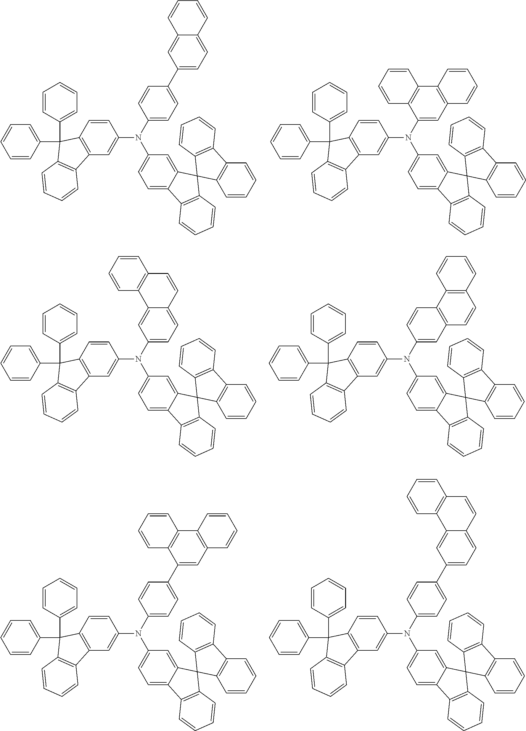


Material for Organic EL Devices

wherein R311 to R316 may be the same or different and each independently represent a cyano group, —CONH2, a carboxyl group, or —COOR317 wherein R317 represents an alkyl group having 1 to 20 carbon atoms or a cycloalkyl group having 3 to 20 carbon atoms; and R311 and R312, R313 and R314, or R315 and R316 may be bonded to each other to form a group represented by —CO—O—CO—.


Evaluation of Emission Efficiency of Organic EL Device
| TABLE A-1 | ||
| Measured results | ||
| Emission | Driving | 80% | ||||
| efficiency | voltage | lifetime | ||||
| First hole | Second hole | (cd/A) | (V) | (h) | ||
| transporting | transporting | @10 mA/ | @10 mA/ | @50 mA/ | ||
| material | material | cm2 | cm2 | cm2 | ||
| Examples |
| A1-1 | X1 | H-A1 | 9.5 | 4.5 | 280 |
| A1-2 | X1 | H-A2 | 9.6 | 4.5 | 280 |
| A1-3 | X1 | H-A3 | 9.5 | 4.4 | 290 |
| A1-4 | X1 | H-A4 | 9.6 | 4.5 | 300 |
| A1-5 | X1 | H-A5 | 9.7 | 4.4 | 290 |
| A1-6 | X1 | H-A6 | 9.6 | 4.5 | 300 |
| A1-7 | X1 | H-A7 | 9.7 | 4.4 | 290 |
| A1-8 | X1 | H-A8 | 9.7 | 4.6 | 320 |
| A1-9 | X1 | H-A9 | 9.5 | 4.3 | 320 |
| A1-10 | X1 | H-A10 | 9.5 | 4.3 | 290 |
| A1-11 | X1 | H-A11 | 9.7 | 4.8 | 300 |
| A1-12 | X1 | H-A12 | 9.7 | 4.8 | 300 |
| A1-13 | X1 | H-A13 | 9.4 | 4.4 | 280 |
| A1-14 | X1 | H-A14 | 9.5 | 4.4 | 290 |
| A1-15 | X1 | H-A15 | 9.4 | 4.3 | 290 |
| A1-16 | X1 | H-A16 | 9.8 | 4.5 | 300 |
| A1-17 | X1 | H-A17 | 9.8 | 4.6 | 290 |
| A1-18 | X1 | H-A18 | 9.7 | 4.4 | 320 |
| Comparative Examples |
| a1-1 | X1 | a1 | 9.8 | 4.8 | 200 |
| a1-2 | X1 | a2 | 9.8 | 4.9 | 220 |
| a1-3 | X1 | a3 | 8.2 | 4.5 | 220 |
| a1-4 | X1 | a4 | 7.8 | 4.3 | 250 |

| TABLE A-2 | ||
| Measured results | ||
| Emission | Driving | 80% | ||||
| efficiency | voltage | lifetime | ||||
| First hole | Second hole | (cd/A) | (V) | (h) | ||
| transporting | transporting | @10 mA/ | @10 mA/ | @50 mA/ | ||
| material | material | cm2 | cm2 | cm2 | ||
| Examples |
| A2-1 | H-A1 | Y1 | 9.5 | 4.4 | 300 |
| A2-2 | H-A2 | Y1 | 9.5 | 4.3 | 300 |
| A2-3 | H-A3 | Y1 | 9.3 | 4.3 | 310 |
| A2-4 | H-A4 | Y1 | 9.3 | 4.4 | 300 |
| A2-5 | H-A5 | Y1 | 9.7 | 4.4 | 300 |
| A2-6 | H-A6 | Y1 | 9.3 | 4.4 | 290 |
| A2-7 | H-A7 | Y1 | 9.6 | 4.4 | 290 |
| A2-8 | H-A8 | Y1 | 9.5 | 4.4 | 300 |
| A2-9 | H-A9 | Y1 | 9.5 | 4.2 | 350 |
| A2-10 | H-A10 | Y1 | 9.4 | 4.2 | 300 |
| A2-11 | H-A11 | Y1 | 10.1 | 4.7 | 310 |
| A2-12 | H-A12 | Y1 | 10.1 | 4.6 | 300 |
| A2-13 | H-A13 | Y1 | 9.5 | 4.3 | 310 |
| A2-14 | H-A14 | Y1 | 9.5 | 4.2 | 320 |
| A2-15 | H-A15 | Y1 | 9.5 | 4.2 | 310 |
| A2-16 | H-A16 | Y1 | 9.5 | 4.4 | 320 |
| A2-17 | H-A17 | Y1 | 9.8 | 4.3 | 320 |
| A2-18 | H-A18 | Y1 | 9.4 | 4.4 | 350 |
| Comparative Examples |
| a2-1 | a1 | Y1 | 9.5 | 4.8 | 250 |
| a2-2 | a2 | Y1 | 9.5 | 5.4 | 220 |


Evaluation of Emission Efficiency of Organic EL Device
| TABLE B-1 | ||
| Measured results | ||
| Emission | Driving | 80% | ||||
| efficiency | voltage | lifetime | ||||
| First hole | Second hole | (cd/A) | (V) | (h) | ||
| transporting | transporting | @10 mA/ | @10 mA/ | @50 mA/ | ||
| material | material | cm2 | cm2 | cm2 | ||
| Examples |
| B1-1 | X1 | H-B1 | 9.4 | 4.0 | 290 |
| B1-2 | X1 | H-B2 | 9.5 | 4.0 | 290 |
| B1-3 | X1 | H-B3 | 9.3 | 3.9 | 300 |
| B1-4 | X1 | H-B4 | 9.3 | 3.9 | 300 |
| B1-5 | X1 | H-B5 | 9.6 | 4.2 | 300 |
| B1-6 | X1 | H-B6 | 9.8 | 4.2 | 290 |
| B1-7 | X1 | H-B7 | 9.6 | 4.2 | 280 |
| B1-8 | X1 | H-B8 | 9.8 | 4.2 | 260 |
| B1-9 | X1 | H-B9 | 9.8 | 4.1 | 300 |
| B1-10 | X1 | H-B10 | 9.3 | 3.9 | 300 |
| B1-11 | X1 | H-B11 | 9.3 | 3.9 | 300 |
| B1-12 | X1 | H-B12 | 9.3 | 3.7 | 280 |
| B1-13 | X1 | H-B13 | 9.3 | 3.8 | 290 |
| B1-14 | X1 | H-B14 | 9.4 | 3.9 | 330 |
| B1-15 | X1 | H-B15 | 9.3 | 3.7 | 300 |
| B1-16 | X1 | H-B16 | 10.0 | 4.3 | 300 |
| B1-17 | X1 | H-B17 | 10.0 | 4.2 | 300 |
| B1-18 | X1 | H-B18 | 9.4 | 3.9 | 310 |
| B1-19 | X1 | H-B19 | 9.6 | 3.9 | 310 |
| B1-20 | X1 | H-B20 | 9.3 | 3.8 | 330 |
| Comparative Examples |
| b1-1 | X1 | b1 | 9.5 | 3.8 | 200 |
| b1-2 | X1 | b2 | 9.8 | 3.9 | 220 |


| TABLE B-2 | ||
| Measured results | ||
| Emission | Driving | 80% | ||||
| efficiency | voltage | lifetime | ||||
| First hole | Second hole | (cd/A) | (V) | (h) | ||
| transporting | transporting | @10 mA/ | @10 mA/ | @50 mA/ | ||
| material | material | cm2 | cm2 | cm2 | ||
| Examples |
| B2-1 | H-B1 | Y1 | 9.7 | 3.8 | 320 |
| B2-2 | H-B2 | Y1 | 9.7 | 3.8 | 320 |
| B2-3 | H-B3 | Y1 | 9.5 | 3.6 | 330 |
| B2-4 | H-B4 | Y1 | 9.5 | 3.7 | 330 |
| B2-5 | H-B5 | Y1 | 9.6 | 3.9 | 330 |
| B2-6 | H-B6 | Y1 | 10.0 | 3.9 | 330 |
| B2-7 | H-B7 | Y1 | 9.5 | 3.9 | 320 |
| B2-8 | H-B8 | Y1 | 9.9 | 3.9 | 320 |
| B2-9 | H-B9 | Y1 | 9.9 | 3.8 | 300 |
| B2-10 | H-B10 | Y1 | 9.7 | 3.8 | 340 |
| B2-11 | H-B11 | Y1 | 9.7 | 3.8 | 330 |
| B2-12 | H-B12 | Y1 | 9.6 | 3.6 | 340 |
| B2-13 | H-B13 | Y1 | 9.6 | 3.7 | 340 |
| B2-14 | H-B14 | Y1 | 9.7 | 3.7 | 350 |
| B2-15 | H-B15 | Y1 | 9.9 | 3.6 | 300 |
| B2-16 | H-B16 | Y1 | 10.2 | 4.0 | 300 |
| B2-17 | H-B17 | Y1 | 10.2 | 4.0 | 300 |
| B2-18 | H-B18 | Y1 | 9.7 | 3.6 | 330 |
| B2-19 | H-B19 | Y1 | 9.8 | 3.5 | 320 |
| B2-20 | H-B20 | Y1 | 9.7 | 3.6 | 350 |
| B2-21 | H-B1 | Y1 | 9.7 | 3.5 | 330 |
| B2-22 | H-B2 | Y1 | 9.8 | 3.5 | 330 |
| B2-23 | H-B3 | Y1 | 9.6 | 3.4 | 340 |
| B2-24 | H-B4 | Y1 | 9.6 | 3.5 | 330 |
| Comparative Examples |
| b2-1 | b1 | Y1 | 9.5 | 3.9 | 250 |
| b2-2 | b2 | Y1 | 9.5 | 4.0 | 220 |
| b2-3 | b1 | Y1 | 9.5 | 3.7 | 260 |
| b2-4 | b2 | Y1 | 9.5 | 3.8 | 220 |


| TABLE B-3 | ||
| Measured results | ||
| External | ||||||
| quantum | Driving | 80% | ||||
| efficiency | voltage | lifetime | ||||
| First hole | Second hole | (EQE) | (V) | (h) | ||
| transporting | transporting | @10 mA/ | @10 mA/ | @50 mA/ | ||
| material | material | cm2 | cm2 | cm2 | ||
| Examples |
| B3-1 | H-B1 | RH-1 | 17.0 | 4.2 | 530 |
| B3-2 | H-B1 | RH-2 | 18.0 | 4.4 | 300 |
| Comparative Examples |
| b3-1 | b1 | RH-1 | 7.5 | 5.2 | 110 |
| b3-2 | b1 | RH-2 | 7.2 | 5.5 | 60 |
- 1: Organic EL device
- 2: Substrate
- 3: Anode
- 4: Cathode
- 5: Light emitting layer
- 6: Anode-side organic thin film layer
- 7: Cathode-side organic thin film layer
- 10: Emission unit
Claims (17)


Applications Claiming Priority (16)
| Application Number | Priority Date | Filing Date | Title |
|---|---|---|---|
| JPJP2014-143249 | 2014-07-11 | ||
| JP2014143248 | 2014-07-11 | ||
| JP2014143249 | 2014-07-11 | ||
| JPJP2014-143248 | 2014-07-11 | ||
| JP2014-143248 | 2014-07-11 | ||
| JP2014-143249 | 2014-07-11 | ||
| JP2014-255559 | 2014-12-17 | ||
| JPJP2014-255562 | 2014-12-17 | ||
| JP2014-255565 | 2014-12-17 | ||
| JPJP2014-255559 | 2014-12-17 | ||
| JP2014255562 | 2014-12-17 | ||
| JP2014255559 | 2014-12-17 | ||
| JPJP2014-255565 | 2014-12-17 | ||
| JP2014-255562 | 2014-12-17 | ||
| JP2014255565 | 2014-12-17 | ||
| PCT/JP2015/070045 WO2016006709A1 (en) | 2014-07-11 | 2015-07-13 | Compound, material for organic electroluminescent element, organic electroluminescent element, and electronic device |
Publications (2)
| Publication Number | Publication Date |
|---|---|
| US20160176801A1 US20160176801A1 (en) | 2016-06-23 |
| US10944057B2 true US10944057B2 (en) | 2021-03-09 |
Family
ID=55064333
Family Applications (3)
| Application Number | Title | Priority Date | Filing Date |
|---|---|---|---|
| US14/909,930 Active 2036-05-12 US10944057B2 (en) | 2014-07-11 | 2015-07-13 | Compound, material for organic electroluminescence devices, organic electroluminescence device, and electronic equipment |
| US14/910,156 Active 2035-07-19 US10516112B2 (en) | 2014-07-11 | 2015-07-13 | Compound, organic electroluminescent element material, organic electroluminescent element, and electronic device |
| US15/308,461 Active 2036-03-10 US10854822B2 (en) | 2014-07-11 | 2015-07-13 | Compound, material for organic electroluminescent element, organic electroluminescent element, and electronic device |
Family Applications After (2)
| Application Number | Title | Priority Date | Filing Date |
|---|---|---|---|
| US14/910,156 Active 2035-07-19 US10516112B2 (en) | 2014-07-11 | 2015-07-13 | Compound, organic electroluminescent element material, organic electroluminescent element, and electronic device |
| US15/308,461 Active 2036-03-10 US10854822B2 (en) | 2014-07-11 | 2015-07-13 | Compound, material for organic electroluminescent element, organic electroluminescent element, and electronic device |
Country Status (6)
| Country | Link |
|---|---|
| US (3) | US10944057B2 (en) |
| EP (3) | EP3018128B1 (en) |
| JP (3) | JP6611055B2 (en) |
| KR (3) | KR102545858B1 (en) |
| CN (3) | CN105431408B (en) |
| WO (3) | WO2016006710A1 (en) |
Families Citing this family (28)
| Publication number | Priority date | Publication date | Assignee | Title |
|---|---|---|---|---|
| WO2014034795A1 (en) * | 2012-08-31 | 2014-03-06 | 出光興産株式会社 | Aromatic amine derivative, and organic electroluminescent element using same |
| US10355217B2 (en) | 2013-12-06 | 2019-07-16 | Merck Patent Gmbh | Compounds and organic electronic devices |
| WO2017148564A1 (en) | 2016-03-03 | 2017-09-08 | Merck Patent Gmbh | Materials for organic electroluminescent devices |
| KR102639784B1 (en) | 2016-10-25 | 2024-02-26 | 삼성디스플레이 주식회사 | Monoamine compound and organic electroluminescence device including the same |
| KR102700186B1 (en) * | 2016-12-27 | 2024-08-29 | 주식회사 동진쎄미켐 | Novel compound and organic electroluminescent divice including the same |
| WO2018154740A1 (en) * | 2017-02-24 | 2018-08-30 | 富士電機株式会社 | Electrophotographic photoreceptor, method for manufacturing same, and electrophotographic device using same |
| JP2020093979A (en) | 2017-03-08 | 2020-06-18 | 出光興産株式会社 | Compound, material for organic electroluminescence device, organic electroluminescence device, and electronic device |
| KR102495414B1 (en) | 2017-03-08 | 2023-02-02 | 이데미쓰 고산 가부시키가이샤 | Chemical compounds, materials for organic electroluminescent devices, organic electroluminescent devices, and electronic devices |
| KR102154386B1 (en) * | 2017-06-16 | 2020-09-09 | 주식회사 엘지화학 | Compound, coating composition comprising the same, organic light emitting device using the same and method of manufacturing the same |
| KR102142676B1 (en) * | 2017-10-24 | 2020-08-07 | 주식회사 엘지화학 | Novel compound and organic light emitting device comprising the same |
| WO2019083122A1 (en) * | 2017-10-24 | 2019-05-02 | 주식회사 엘지화학 | Novel compound and organic light emitting element using same |
| KR102578544B1 (en) | 2017-12-11 | 2023-09-13 | 엘지디스플레이 주식회사 | Electroluminescent Display Device |
| EP3502107B1 (en) * | 2017-12-20 | 2022-01-26 | Samsung Display Co., Ltd. | 1-aminodibenzofuran-based compound and organic light-emitting device including the same |
| KR102240075B1 (en) * | 2018-02-28 | 2021-04-13 | 주식회사 엘지화학 | Organic light emitting device |
| WO2019185060A1 (en) * | 2018-03-29 | 2019-10-03 | 江苏三月光电科技有限公司 | Compound using arylamine-attached bi-dimethylfluorene as nucleus, and application thereof |
| CN110317140B (en) * | 2018-03-29 | 2022-05-13 | 江苏三月科技股份有限公司 | Compound with arylamine and bis-dimethyl fluorene as cores and application thereof |
| WO2019192954A1 (en) * | 2018-04-04 | 2019-10-10 | Merck Patent Gmbh | Materials for electronic devices |
| JP2021167278A (en) * | 2018-05-10 | 2021-10-21 | 出光興産株式会社 | Compound, material for organic electroluminescent element, organic electroluminescent element, and electronic device |
| KR102559633B1 (en) * | 2018-05-31 | 2023-08-02 | 주식회사 동진쎄미켐 | Novel compound and organic electroluminescent divice including the same |
| WO2020075964A1 (en) * | 2018-10-10 | 2020-04-16 | 주식회사 엘지화학 | Novel compound and organic light emitting diode comprising same |
| CN109293516B (en) * | 2018-11-03 | 2022-01-14 | 长春海谱润斯科技股份有限公司 | Triarylamine compound and organic light-emitting device thereof |
| JP7461300B2 (en) | 2018-11-30 | 2024-04-03 | 出光興産株式会社 | Compound, material for organic electroluminescence device, organic electroluminescence device, and electronic device |
| CN113166088A (en) | 2018-12-20 | 2021-07-23 | 默克专利有限公司 | Material for electronic devices |
| WO2021149954A1 (en) * | 2020-01-23 | 2021-07-29 | 주식회사 엘지화학 | Organic light emitting device |
| KR20220086754A (en) | 2020-12-16 | 2022-06-24 | 삼성디스플레이 주식회사 | Organic electroluminescence device and amine compound for organic electroluminescence device |
| EP4227289A4 (en) * | 2021-01-11 | 2024-06-26 | Lg Chem, Ltd. | Novel compound, coating composition comprising same, organic light-emitting device using same and manufacturing method therefor |
| CN117343078A (en) | 2021-11-25 | 2024-01-05 | 北京夏禾科技有限公司 | Organic electroluminescent materials and devices |
| CN116283725B (en) * | 2023-01-16 | 2025-06-24 | 烟台显华科技集团股份有限公司 | Aromatic amine substituted dibenzo five-membered ring compound and its application |
Citations (39)
| Publication number | Priority date | Publication date | Assignee | Title |
|---|---|---|---|---|
| JPH06102683A (en) | 1992-09-21 | 1994-04-15 | Canon Inc | Electrophotographic photoreceptor, electrophotographic apparatus and facsimile equipped with the electrophotographic photoreceptor |
| JPH1095972A (en) | 1996-08-02 | 1998-04-14 | Mitsui Petrochem Ind Ltd | Organic electroluminescent device |
| JPH11144875A (en) | 1997-11-06 | 1999-05-28 | Mitsui Chem Inc | Organic electroluminescent element |
| JPH11184119A (en) | 1997-12-17 | 1999-07-09 | Canon Inc | Electrophotographic photoreceptor, process cartridge having the electrophotographic photoreceptor, and electrophotographic apparatus |
| US20030118866A1 (en) | 2001-10-30 | 2003-06-26 | Lg Electronics Inc. | Organic electroluminescent device |
| US20040157084A1 (en) * | 2003-02-07 | 2004-08-12 | Samsung Sdi Co., Ltd. | Emitting compound for organic electroluminescent device and organic electroluminescent device using the same |
| US20060232198A1 (en) | 2005-04-18 | 2006-10-19 | Idemitsu Kosan Co., Ltd. | Aromatic triamine compound and organic electroluminescence device using the same |
| US20070278938A1 (en) | 2006-04-26 | 2007-12-06 | Idemitsu Kosan Co., Ltd. | Aromatic amine derivative and electroluminescence device using the same |
| JP2008300503A (en) | 2007-05-30 | 2008-12-11 | Sony Corp | Organic electroluminescence device and display device |
| CN101341115A (en) | 2005-12-20 | 2009-01-07 | 佳能株式会社 | 4-aminofluorene compounds and organic light-emitting devices |
| JP2009010364A (en) | 2007-05-30 | 2009-01-15 | Sony Corp | Organic electroluminescence device and display device |
| WO2011021520A1 (en) | 2009-08-19 | 2011-02-24 | 出光興産株式会社 | Aromatic amine derivatives and organic electroluminescent elements using same |
| JP2011187959A (en) | 2010-03-08 | 2011-09-22 | Samsung Mobile Display Co Ltd | Organic light-emitting device, and method of manufacturing the same |
| WO2012011642A1 (en) | 2010-07-23 | 2012-01-26 | 고려대학교 산학협력단 | Quasi-solid polymer electrolyte for dye-sensitized solar cell, hole transport material contained in same, and dye-sensitized solar cell containing the electrolyte |
| US20120181530A1 (en) | 2009-10-01 | 2012-07-19 | Shigeaki Funyuu | Material for organic electronics, organic electronic element, organic electroluminescent element, display element using organic electroluminescent element, illuminating device, and display device |
| US20130105771A1 (en) | 2010-04-23 | 2013-05-02 | Dong-wan Ryu | Compound for optoelectronic device, organic light emitting diode including the same, and display including the organic light emitting diode |
| WO2013087142A1 (en) | 2011-12-12 | 2013-06-20 | Merck Patent Gmbh | Compounds for electronic devices |
| KR20130096334A (en) | 2011-06-24 | 2013-08-30 | 덕산하이메탈(주) | Organic electronic element, and a compound for the same |
| KR20130121597A (en) | 2012-04-27 | 2013-11-06 | (주)위델소재 | Using triphenylamine as hole transporting mateial and organic electroluminescent device using the same |
| WO2013182263A1 (en) | 2012-06-06 | 2013-12-12 | Merck Patent Gmbh | Phenanthrene compounds for organic electronic devices |
| WO2014015935A2 (en) | 2012-07-23 | 2014-01-30 | Merck Patent Gmbh | Compounds and organic electronic devices |
| WO2014015937A1 (en) | 2012-07-23 | 2014-01-30 | Merck Patent Gmbh | Compounds and organic electroluminescent devices |
| US20140042411A1 (en) | 2011-04-08 | 2014-02-13 | Fujifilm Corporation | Method for purifying organic material, material for organic electronics, photoelectric conversion device, optical sensor, imaging device, and organic electroluminescence device |
| KR20140024734A (en) | 2012-08-21 | 2014-03-03 | 롬엔드하스전자재료코리아유한회사 | Novel organic electroluminescence compounds and organic electroluminescence device containing the same |
| WO2014034795A1 (en) | 2012-08-31 | 2014-03-06 | 出光興産株式会社 | Aromatic amine derivative, and organic electroluminescent element using same |
| KR101389527B1 (en) | 2013-09-17 | 2014-04-25 | 덕산하이메탈(주) | Organic electronic element using a compound for organic electronic element, and an electronic device thereof |
| CN103755574A (en) | 2014-01-26 | 2014-04-30 | 黑龙江省科学院石油化学研究院 | Method for synthesizing tri(9,9-dialkyl-9H-fluorenyl) amine with multiphoton absorption property |
| WO2014088285A1 (en) | 2012-12-06 | 2014-06-12 | 덕산하이메탈(주) | Compound for organic electronic element, organic electronic element using same, and electronic device therewith |
| WO2014112728A1 (en) | 2013-01-17 | 2014-07-24 | 희성소재(주) | Pyrazole-based compound and organic light emitting device using same |
| KR20140098502A (en) | 2013-01-31 | 2014-08-08 | 덕산하이메탈(주) | Compound for organic electronic element, organic electronic element using the same, and a electronic device thereof |
| US20140291643A1 (en) * | 2013-03-26 | 2014-10-02 | Semiconductor Energy Laboratory Co., Ltd. | Organic Compound, Light-Emitting Element, Light-Emitting Device, Display Device, Electronic Device, and Lighting Device |
| KR20150007476A (en) | 2013-07-11 | 2015-01-21 | 덕산하이메탈(주) | Organic electronic element using a compound for organic electronic element, and an electronic device thereof |
| US20150065730A1 (en) * | 2012-02-14 | 2015-03-05 | Merck Patent Gmbh | Spirobifluorene compounds for organic electroluminescent devices |
| WO2015041428A1 (en) | 2013-09-17 | 2015-03-26 | 덕산네오룩스 주식회사 | Organic electronic element using compound for organic electronic element and electronic device thereof |
| WO2015082056A1 (en) | 2013-12-06 | 2015-06-11 | Merck Patent Gmbh | Compounds and organic electronic devices |
| KR101530049B1 (en) | 2014-10-24 | 2015-06-18 | 덕산네오룩스 주식회사 | Display device using a composition for organic electronic element, and an organic electronic element thereof |
| WO2015162912A1 (en) | 2014-04-21 | 2015-10-29 | 出光興産株式会社 | Organic electroluminescent element |
| WO2016122150A2 (en) | 2015-01-29 | 2016-08-04 | 덕산네오룩스 주식회사 | Compound for organic electronic element, organic electronic element using same, and electronic device thereof |
| US20170373254A1 (en) | 2014-06-03 | 2017-12-28 | Samsung Display Co., Ltd. | Organic light-emitting device |
Family Cites Families (3)
| Publication number | Priority date | Publication date | Assignee | Title |
|---|---|---|---|---|
| KR20120011445A (en) | 2010-07-29 | 2012-02-08 | 롬엔드하스전자재료코리아유한회사 | Novel organic light emitting compound and organic electroluminescent device comprising same |
| KR102098061B1 (en) * | 2012-03-19 | 2020-04-08 | 덕산네오룩스 주식회사 | Compound for organic electronic element, organic electronic element using the same, and a electronic device thereof |
| US9291301B2 (en) * | 2012-08-06 | 2016-03-22 | Donald Allan Brinkmann | Support device |
-
2015
- 2015-07-13 KR KR1020167002762A patent/KR102545858B1/en active Active
- 2015-07-13 US US14/909,930 patent/US10944057B2/en active Active
- 2015-07-13 US US14/910,156 patent/US10516112B2/en active Active
- 2015-07-13 US US15/308,461 patent/US10854822B2/en active Active
- 2015-07-13 CN CN201580001554.6A patent/CN105431408B/en active Active
- 2015-07-13 WO PCT/JP2015/070046 patent/WO2016006710A1/en not_active Ceased
- 2015-07-13 WO PCT/JP2015/070045 patent/WO2016006709A1/en not_active Ceased
- 2015-07-13 JP JP2016504820A patent/JP6611055B2/en active Active
- 2015-07-13 JP JP2016504413A patent/JP6601627B2/en active Active
- 2015-07-13 CN CN201580001555.0A patent/CN105431417A/en active Pending
- 2015-07-13 KR KR1020167002841A patent/KR102387509B1/en active Active
- 2015-07-13 KR KR1020167002768A patent/KR102398726B1/en active Active
- 2015-07-13 WO PCT/JP2015/070047 patent/WO2016006711A1/en not_active Ceased
- 2015-07-13 EP EP15819013.2A patent/EP3018128B1/en active Active
- 2015-07-13 EP EP15818448.1A patent/EP3127894B1/en active Active
- 2015-07-13 CN CN201580001549.5A patent/CN105658619A/en active Pending
- 2015-07-13 EP EP15818619.7A patent/EP3018120B1/en active Active
- 2015-07-13 JP JP2015560883A patent/JP6611043B2/en active Active
Patent Citations (47)
| Publication number | Priority date | Publication date | Assignee | Title |
|---|---|---|---|---|
| JPH06102683A (en) | 1992-09-21 | 1994-04-15 | Canon Inc | Electrophotographic photoreceptor, electrophotographic apparatus and facsimile equipped with the electrophotographic photoreceptor |
| JPH1095972A (en) | 1996-08-02 | 1998-04-14 | Mitsui Petrochem Ind Ltd | Organic electroluminescent device |
| JPH11144875A (en) | 1997-11-06 | 1999-05-28 | Mitsui Chem Inc | Organic electroluminescent element |
| JPH11184119A (en) | 1997-12-17 | 1999-07-09 | Canon Inc | Electrophotographic photoreceptor, process cartridge having the electrophotographic photoreceptor, and electrophotographic apparatus |
| US20030118866A1 (en) | 2001-10-30 | 2003-06-26 | Lg Electronics Inc. | Organic electroluminescent device |
| US20040157084A1 (en) * | 2003-02-07 | 2004-08-12 | Samsung Sdi Co., Ltd. | Emitting compound for organic electroluminescent device and organic electroluminescent device using the same |
| US20090115320A1 (en) | 2005-04-18 | 2009-05-07 | Idemitsu Kosan Co., Ltd. | Aromatic triamine compound and organic electtroluminescence device using the same |
| US20060232198A1 (en) | 2005-04-18 | 2006-10-19 | Idemitsu Kosan Co., Ltd. | Aromatic triamine compound and organic electroluminescence device using the same |
| US20100033081A1 (en) * | 2005-12-20 | 2010-02-11 | Canon Kabushiki Kaisha | 4-aminofluorene compound and organic light emitting device |
| CN101341115A (en) | 2005-12-20 | 2009-01-07 | 佳能株式会社 | 4-aminofluorene compounds and organic light-emitting devices |
| US20070278938A1 (en) | 2006-04-26 | 2007-12-06 | Idemitsu Kosan Co., Ltd. | Aromatic amine derivative and electroluminescence device using the same |
| JP2009010364A (en) | 2007-05-30 | 2009-01-15 | Sony Corp | Organic electroluminescence device and display device |
| JP2008300503A (en) | 2007-05-30 | 2008-12-11 | Sony Corp | Organic electroluminescence device and display device |
| WO2011021520A1 (en) | 2009-08-19 | 2011-02-24 | 出光興産株式会社 | Aromatic amine derivatives and organic electroluminescent elements using same |
| US20120146014A1 (en) | 2009-08-19 | 2012-06-14 | Idemitsu Kosan Co., Ltd. | Aromatic amine derivatives and organic electroluminescent elements using same |
| US20120181530A1 (en) | 2009-10-01 | 2012-07-19 | Shigeaki Funyuu | Material for organic electronics, organic electronic element, organic electroluminescent element, display element using organic electroluminescent element, illuminating device, and display device |
| JP2011187959A (en) | 2010-03-08 | 2011-09-22 | Samsung Mobile Display Co Ltd | Organic light-emitting device, and method of manufacturing the same |
| US20130105771A1 (en) | 2010-04-23 | 2013-05-02 | Dong-wan Ryu | Compound for optoelectronic device, organic light emitting diode including the same, and display including the organic light emitting diode |
| WO2012011642A1 (en) | 2010-07-23 | 2012-01-26 | 고려대학교 산학협력단 | Quasi-solid polymer electrolyte for dye-sensitized solar cell, hole transport material contained in same, and dye-sensitized solar cell containing the electrolyte |
| US20140042411A1 (en) | 2011-04-08 | 2014-02-13 | Fujifilm Corporation | Method for purifying organic material, material for organic electronics, photoelectric conversion device, optical sensor, imaging device, and organic electroluminescence device |
| KR20130096334A (en) | 2011-06-24 | 2013-08-30 | 덕산하이메탈(주) | Organic electronic element, and a compound for the same |
| WO2013087142A1 (en) | 2011-12-12 | 2013-06-20 | Merck Patent Gmbh | Compounds for electronic devices |
| US20150065730A1 (en) * | 2012-02-14 | 2015-03-05 | Merck Patent Gmbh | Spirobifluorene compounds for organic electroluminescent devices |
| KR20130121597A (en) | 2012-04-27 | 2013-11-06 | (주)위델소재 | Using triphenylamine as hole transporting mateial and organic electroluminescent device using the same |
| WO2013182263A1 (en) | 2012-06-06 | 2013-12-12 | Merck Patent Gmbh | Phenanthrene compounds for organic electronic devices |
| US20150179940A1 (en) * | 2012-07-23 | 2015-06-25 | Merck Patent Gmbh | Compounds and organic electronic devices |
| WO2014015935A2 (en) | 2012-07-23 | 2014-01-30 | Merck Patent Gmbh | Compounds and organic electronic devices |
| WO2014015937A1 (en) | 2012-07-23 | 2014-01-30 | Merck Patent Gmbh | Compounds and organic electroluminescent devices |
| US20150179953A1 (en) | 2012-07-23 | 2015-06-25 | Merck Patent Gmbh | Compounds and organic electroluminescent devices |
| KR20140024734A (en) | 2012-08-21 | 2014-03-03 | 롬엔드하스전자재료코리아유한회사 | Novel organic electroluminescence compounds and organic electroluminescence device containing the same |
| WO2014034795A1 (en) | 2012-08-31 | 2014-03-06 | 出光興産株式会社 | Aromatic amine derivative, and organic electroluminescent element using same |
| US20150243891A1 (en) | 2012-08-31 | 2015-08-27 | Idemitsu Kosan Co., Ltd. | Aromatic amine derivative, and organic electroluminescent element using same |
| EP2891648A1 (en) | 2012-08-31 | 2015-07-08 | Idemitsu Kosan Co., Ltd | Aromatic amine derivative, and organic electroluminescent element using same |
| WO2014088285A1 (en) | 2012-12-06 | 2014-06-12 | 덕산하이메탈(주) | Compound for organic electronic element, organic electronic element using same, and electronic device therewith |
| WO2014112728A1 (en) | 2013-01-17 | 2014-07-24 | 희성소재(주) | Pyrazole-based compound and organic light emitting device using same |
| KR20140098502A (en) | 2013-01-31 | 2014-08-08 | 덕산하이메탈(주) | Compound for organic electronic element, organic electronic element using the same, and a electronic device thereof |
| US20140291643A1 (en) * | 2013-03-26 | 2014-10-02 | Semiconductor Energy Laboratory Co., Ltd. | Organic Compound, Light-Emitting Element, Light-Emitting Device, Display Device, Electronic Device, and Lighting Device |
| KR20150007476A (en) | 2013-07-11 | 2015-01-21 | 덕산하이메탈(주) | Organic electronic element using a compound for organic electronic element, and an electronic device thereof |
| WO2015041428A1 (en) | 2013-09-17 | 2015-03-26 | 덕산네오룩스 주식회사 | Organic electronic element using compound for organic electronic element and electronic device thereof |
| KR101389527B1 (en) | 2013-09-17 | 2014-04-25 | 덕산하이메탈(주) | Organic electronic element using a compound for organic electronic element, and an electronic device thereof |
| WO2015082056A1 (en) | 2013-12-06 | 2015-06-11 | Merck Patent Gmbh | Compounds and organic electronic devices |
| US20160301005A1 (en) | 2013-12-06 | 2016-10-13 | Merck Patent Gmbh | Compounds and organic electronic devices |
| CN103755574A (en) | 2014-01-26 | 2014-04-30 | 黑龙江省科学院石油化学研究院 | Method for synthesizing tri(9,9-dialkyl-9H-fluorenyl) amine with multiphoton absorption property |
| WO2015162912A1 (en) | 2014-04-21 | 2015-10-29 | 出光興産株式会社 | Organic electroluminescent element |
| US20170373254A1 (en) | 2014-06-03 | 2017-12-28 | Samsung Display Co., Ltd. | Organic light-emitting device |
| KR101530049B1 (en) | 2014-10-24 | 2015-06-18 | 덕산네오룩스 주식회사 | Display device using a composition for organic electronic element, and an organic electronic element thereof |
| WO2016122150A2 (en) | 2015-01-29 | 2016-08-04 | 덕산네오룩스 주식회사 | Compound for organic electronic element, organic electronic element using same, and electronic device thereof |
Non-Patent Citations (24)
| Title |
|---|
| Chinese Office Action dated Apr. 28, 2020 in Patent Application No. 201580001554.6, 5 pages. |
| Chinese Office Action dated Apr. 3, 2020 in Chinese Patent Application No. 201580001555.0, 5 pages. |
| Combined Office Action and Search Report dated Sep. 28, 2018 in Chinese Patent Application No. 201580001555.0 (with English translation of categories of cited documents). |
| Extended European Search Report dated Nov. 24, 2016 in Patent Application No. 15819013.2. |
| International Search Report dated Oct. 6, 201 5 in PCT/JP2015/070045. |
| Notification of Reasons for Refusal dated Mar. 5, 2019 in Japanese Patent Application No. 2016-504413 with machine generated English translation. |
| Office Action (Notification of Reasons for Refusal) dated Feb. 5, 2019 in Japanese Patent Application No. 2016-504820 with computer generated English translation. |
| Office Action as received in the corresponding Chinese Patent Application No. 201580001549.5 dated Nov. 4, 2019 / English Translation not available, 10 pages. |
| Office Action as received in the corresponding Chinese Patent Application No. 201580001554.6 dated May 21, 2016 w/English Translation. |
| Office Action dated Apr. 3, 2020 in co-pending U.S. Appl. No. 15/308,461, 21 pages. |
| Office Action dated Aug. 28, 2018 in the corresponding Japanese patent application with machine English translation (JP-OA 2015-560883. |
| Office Action dated Aug. 28, 2018 in the corresponding Japanese patent application with machine English translation (JP-OA 2016-504820). |
| Office Action dated Dec. 13, 2018 in co-pending U.S. Appl. No. 15/308,461, 20 pages. |
| Office Action dated Feb. 5, 2020 in European Patent Application No. 15 818 448.1 filed Jul. 13, 2015, 5 pages. |
| Office Action dated Jun. 21, 2019 in European Patent Application No. 15 818 448.1. |
| Office Action dated May 17, 2019 in co-pending U.S. Appl. No. 15/308,461, 16 pages. |
| Office Action dated Nov. 16, 2018 in European Patent Application No. 15 818 619.7. |
| Office Action dated Nov. 8, 2018 in European Patent Application No. 15 818 448.1. |
| Office Action in Chinese Application No. 201580001549.5, dated Jul. 23, 2020. |
| Office Action in Chinese Application No. 201580001555.0: dated Jan. 13, 2021. |
| Office Acton (Notification of Reasons for Refusal) dated Feb. 5, 2019 in Japanese Patent Application No. 2015-560883 with computer generated English translation. |
| The Second Office Action dated Feb. 22, 2019 in Chinese Patent Application No. 20158001549.5 with machine generated English translation. |
| The Second Office Action dated June 17, 2019 in Chinese Patent Appiication No. 201580001555.0 with machine generated English translation. |
| The Third Office Action dated Oct. 16, 2019 in Chinese Patent Application No. 201580001554.6 with computer-generated English translation, 12 pages. |
Also Published As
Similar Documents
| Publication | Publication Date | Title |
|---|---|---|
| US10944057B2 (en) | Compound, material for organic electroluminescence devices, organic electroluminescence device, and electronic equipment | |
| US10756275B2 (en) | Compound, material for organic electroluminescence devices, organic electroluminescence device, and electronic equipment | |
| US10243148B2 (en) | Aromatic amine compound, and organic electroluminescent elements including the compound | |
| US12274162B2 (en) | Compound, material for organic electroluminescent element, organic electroluminescent element, and electronic apparatus | |
| US20230047512A1 (en) | Compound and organic electroluminescent element using same | |
| US10790449B2 (en) | Compound, material for organic electroluminescence element, organic electroluminescence element, and electronic device | |
| US20180029983A1 (en) | Compound, organic electroluminescent element material, organic electroluminescent element, and electronic device |
Legal Events
| Date | Code | Title | Description |
|---|---|---|---|
| AS | Assignment |
Owner name: IDEMITSU KOSAN CO., LTD., JAPAN Free format text: ASSIGNMENT OF ASSIGNORS INTEREST;ASSIGNORS:KATO, TOMOKI;YABUNOUCHI, NOBUHIRO;FUNAHASHI, MASAKAZU;AND OTHERS;SIGNING DATES FROM 20160113 TO 20160127;REEL/FRAME:037658/0857 |
|
| STPP | Information on status: patent application and granting procedure in general |
Free format text: FINAL REJECTION MAILED |
|
| STPP | Information on status: patent application and granting procedure in general |
Free format text: RESPONSE AFTER FINAL ACTION FORWARDED TO EXAMINER |
|
| STPP | Information on status: patent application and granting procedure in general |
Free format text: ADVISORY ACTION MAILED |
|
| STPP | Information on status: patent application and granting procedure in general |
Free format text: DOCKETED NEW CASE - READY FOR EXAMINATION |
|
| STPP | Information on status: patent application and granting procedure in general |
Free format text: NON FINAL ACTION MAILED |
|
| STPP | Information on status: patent application and granting procedure in general |
Free format text: DOCKETED NEW CASE - READY FOR EXAMINATION |
|
| STCF | Information on status: patent grant |
Free format text: PATENTED CASE |
|
| MAFP | Maintenance fee payment |
Free format text: PAYMENT OF MAINTENANCE FEE, 4TH YEAR, LARGE ENTITY (ORIGINAL EVENT CODE: M1551); ENTITY STATUS OF PATENT OWNER: LARGE ENTITY Year of fee payment: 4 |