US10935919B2 - Image forming apparatus - Google Patents
Image forming apparatus Download PDFInfo
- Publication number
- US10935919B2 US10935919B2 US16/561,869 US201916561869A US10935919B2 US 10935919 B2 US10935919 B2 US 10935919B2 US 201916561869 A US201916561869 A US 201916561869A US 10935919 B2 US10935919 B2 US 10935919B2
- Authority
- US
- United States
- Prior art keywords
- image forming
- temperature
- color misregistration
- correction
- forming apparatus
- Prior art date
- Legal status (The legal status is an assumption and is not a legal conclusion. Google has not performed a legal analysis and makes no representation as to the accuracy of the status listed.)
- Active
Links
- 238000012546 transfer Methods 0.000 claims abstract description 70
- 239000003086 colorant Substances 0.000 claims abstract description 15
- 238000001514 detection method Methods 0.000 claims description 65
- 108091008695 photoreceptors Proteins 0.000 claims description 8
- 238000005259 measurement Methods 0.000 claims description 2
- 238000012937 correction Methods 0.000 abstract description 156
- 230000015572 biosynthetic process Effects 0.000 abstract description 23
- 238000012545 processing Methods 0.000 description 48
- 230000008859 change Effects 0.000 description 12
- 230000003287 optical effect Effects 0.000 description 11
- 238000004364 calculation method Methods 0.000 description 10
- 239000004065 semiconductor Substances 0.000 description 9
- 238000002849 thermal shift Methods 0.000 description 8
- 230000005484 gravity Effects 0.000 description 7
- 238000010586 diagram Methods 0.000 description 6
- 239000000758 substrate Substances 0.000 description 6
- 101100208381 Caenorhabditis elegans tth-1 gene Proteins 0.000 description 4
- 230000006870 function Effects 0.000 description 3
- 238000004590 computer program Methods 0.000 description 2
- 239000010432 diamond Substances 0.000 description 2
- 230000001678 irradiating effect Effects 0.000 description 2
- 230000007246 mechanism Effects 0.000 description 2
- 238000000034 method Methods 0.000 description 2
- 238000012805 post-processing Methods 0.000 description 2
- 230000008569 process Effects 0.000 description 2
- 230000009467 reduction Effects 0.000 description 2
- 230000004044 response Effects 0.000 description 2
- 238000011144 upstream manufacturing Methods 0.000 description 2
- 238000004378 air conditioning Methods 0.000 description 1
- 230000008901 benefit Effects 0.000 description 1
- 230000002542 deteriorative effect Effects 0.000 description 1
- 238000011161 development Methods 0.000 description 1
- 230000007613 environmental effect Effects 0.000 description 1
- 238000010438 heat treatment Methods 0.000 description 1
- 238000012986 modification Methods 0.000 description 1
- 230000004048 modification Effects 0.000 description 1
- 230000004043 responsiveness Effects 0.000 description 1
- 238000007790 scraping Methods 0.000 description 1
Images


Classifications
-
- G—PHYSICS
- G03—PHOTOGRAPHY; CINEMATOGRAPHY; ANALOGOUS TECHNIQUES USING WAVES OTHER THAN OPTICAL WAVES; ELECTROGRAPHY; HOLOGRAPHY
- G03G—ELECTROGRAPHY; ELECTROPHOTOGRAPHY; MAGNETOGRAPHY
- G03G15/00—Apparatus for electrographic processes using a charge pattern
- G03G15/50—Machine control of apparatus for electrographic processes using a charge pattern, e.g. regulating differents parts of the machine, multimode copiers, microprocessor control
- G03G15/5054—Machine control of apparatus for electrographic processes using a charge pattern, e.g. regulating differents parts of the machine, multimode copiers, microprocessor control by measuring the characteristics of an intermediate image carrying member or the characteristics of an image on an intermediate image carrying member, e.g. intermediate transfer belt or drum, conveyor belt
-
- G—PHYSICS
- G03—PHOTOGRAPHY; CINEMATOGRAPHY; ANALOGOUS TECHNIQUES USING WAVES OTHER THAN OPTICAL WAVES; ELECTROGRAPHY; HOLOGRAPHY
- G03G—ELECTROGRAPHY; ELECTROPHOTOGRAPHY; MAGNETOGRAPHY
- G03G15/00—Apparatus for electrographic processes using a charge pattern
- G03G15/65—Apparatus which relate to the handling of copy material
- G03G15/6555—Handling of sheet copy material taking place in a specific part of the copy material feeding path
- G03G15/6558—Feeding path after the copy sheet preparation and up to the transfer point, e.g. registering; Deskewing; Correct timing of sheet feeding to the transfer point
- G03G15/6561—Feeding path after the copy sheet preparation and up to the transfer point, e.g. registering; Deskewing; Correct timing of sheet feeding to the transfer point for sheet registration
-
- G—PHYSICS
- G03—PHOTOGRAPHY; CINEMATOGRAPHY; ANALOGOUS TECHNIQUES USING WAVES OTHER THAN OPTICAL WAVES; ELECTROGRAPHY; HOLOGRAPHY
- G03G—ELECTROGRAPHY; ELECTROPHOTOGRAPHY; MAGNETOGRAPHY
- G03G15/00—Apparatus for electrographic processes using a charge pattern
- G03G15/50—Machine control of apparatus for electrographic processes using a charge pattern, e.g. regulating differents parts of the machine, multimode copiers, microprocessor control
- G03G15/5054—Machine control of apparatus for electrographic processes using a charge pattern, e.g. regulating differents parts of the machine, multimode copiers, microprocessor control by measuring the characteristics of an intermediate image carrying member or the characteristics of an image on an intermediate image carrying member, e.g. intermediate transfer belt or drum, conveyor belt
- G03G15/5058—Machine control of apparatus for electrographic processes using a charge pattern, e.g. regulating differents parts of the machine, multimode copiers, microprocessor control by measuring the characteristics of an intermediate image carrying member or the characteristics of an image on an intermediate image carrying member, e.g. intermediate transfer belt or drum, conveyor belt using a test patch
-
- G—PHYSICS
- G03—PHOTOGRAPHY; CINEMATOGRAPHY; ANALOGOUS TECHNIQUES USING WAVES OTHER THAN OPTICAL WAVES; ELECTROGRAPHY; HOLOGRAPHY
- G03G—ELECTROGRAPHY; ELECTROPHOTOGRAPHY; MAGNETOGRAPHY
- G03G15/00—Apparatus for electrographic processes using a charge pattern
- G03G15/01—Apparatus for electrographic processes using a charge pattern for producing multicoloured copies
- G03G15/0105—Details of unit
- G03G15/0131—Details of unit for transferring a pattern to a second base
-
- G—PHYSICS
- G03—PHOTOGRAPHY; CINEMATOGRAPHY; ANALOGOUS TECHNIQUES USING WAVES OTHER THAN OPTICAL WAVES; ELECTROGRAPHY; HOLOGRAPHY
- G03G—ELECTROGRAPHY; ELECTROPHOTOGRAPHY; MAGNETOGRAPHY
- G03G15/00—Apparatus for electrographic processes using a charge pattern
- G03G15/04—Apparatus for electrographic processes using a charge pattern for exposing, i.e. imagewise exposure by optically projecting the original image on a photoconductive recording material
- G03G15/04036—Details of illuminating systems, e.g. lamps, reflectors
-
- G—PHYSICS
- G03—PHOTOGRAPHY; CINEMATOGRAPHY; ANALOGOUS TECHNIQUES USING WAVES OTHER THAN OPTICAL WAVES; ELECTROGRAPHY; HOLOGRAPHY
- G03G—ELECTROGRAPHY; ELECTROPHOTOGRAPHY; MAGNETOGRAPHY
- G03G15/00—Apparatus for electrographic processes using a charge pattern
- G03G15/14—Apparatus for electrographic processes using a charge pattern for transferring a pattern to a second base
- G03G15/16—Apparatus for electrographic processes using a charge pattern for transferring a pattern to a second base of a toner pattern, e.g. a powder pattern, e.g. magnetic transfer
- G03G15/1605—Apparatus for electrographic processes using a charge pattern for transferring a pattern to a second base of a toner pattern, e.g. a powder pattern, e.g. magnetic transfer using at least one intermediate support
- G03G15/1615—Apparatus for electrographic processes using a charge pattern for transferring a pattern to a second base of a toner pattern, e.g. a powder pattern, e.g. magnetic transfer using at least one intermediate support relating to the driving mechanism for the intermediate support, e.g. gears, couplings, belt tensioning
Definitions
- the present disclosure relates to an image forming apparatus such as a laser printer, a digital copier and the like which performs image formation by scanning a laser beam.
- An image forming apparatus which forms a color image by an electrophotographic system includes a plurality of image forming portions for increasing speed. Each image forming portion forms an image of a corresponding color on a photoreceptor by, for example, each step of charging, exposure, and development. The image formed on the photoreceptor of each image forming portion is sequentially superimposed on and transferred to a transfer member and a sheet, and a full-color image is formed.
- a laser scanner is used to expose the photoreceptor. The laser scanner exposes the photoreceptor by deflecting a laser beam by a deflector. The deflector generates heat.
- optical components such as a lens, a mirror and the like are deformed, or a position or an attitude of the optical component changes. These changes of the optical system result in deviation of an irradiation position of the laser beam.
- the deviation of the irradiation position causes the deviation between images when the images of the respective colors are superimposed. Due to the deviation between images, color misregistration occurs in the color image.
- the image forming apparatus performs color misregistration correction to the color misregistration.
- the color misregistration correction is performed by forming a detection image for detecting color misregistration on a transfer member to which the image is transferred from the photoreceptor, by detecting a color misregistration correction value by reading the detection image by a sensor, and by adjusting image-writing start timing and the like according to the color misregistration correction value.
- the image-writing start timing is timing to start the exposure of the photoreceptor with the laser scanner.
- the color misregistration correction is hereinafter referred to as “auto registration”.
- the auto registration is performed at appropriate time intervals or for every predetermined number of sheets on which the image formation is performed.
- necessity to perform the auto registration increases. Frequent auto-registration leads to increased downtime.
- a state in the image forming apparatus when a power source is turned on is often similar to that when the power source is previously turned on.
- 8,107,833 B2 proposes an image forming apparatus in which, if a difference with a temperature of the image forming apparatus when the power source is previously turned on is less than a predetermined temperature, the color misregistration correction value when the power source is previously turned on is used, and if the difference is a predetermined temperature or more, a new color misregistration value is detected.
- Timing to turn on the power source of the image forming apparatus varies depending on the day.
- a temperature outside the image forming apparatus and a temperature inside the image forming apparatus also vary.
- the variation in the temperature directly influences a color misregistration amount so that correction residual due to the color misregistration correction becomes large. If the correction residual is unacceptably large, frequency to perform the auto registration increases.
- a conventional image forming apparatus determines whether to perform the auto registration when the power source is turned on. In an actual operation, the image forming apparatus also performs the auto registration after the image forming apparatus is left unoperated for a long time.
- an image forming apparatus which reduces the frequency to perform the auto registration to reduce the downtime is desired.
- An image forming apparatus includes: a plurality of image forming units configured to form a plurality of images of different colors; an intermediate transfer member to which the images are transferred; a transfer portion to which the images are transferred from the intermediate transfer member to a sheet; a sensor configured to measure color patterns on the intermediate transfer member, the color patterns being used to detect color misregistration; a detector configured to detect a temperature; a controller configured to control the plurality of image forming units to form color patterns of different colors, control the sensor to measure the color patterns, detect the color misregistration on the basis of a measurement result of the sensor, control a relative position of images to be formed by the plurality of image forming units on the basis of the detected color misregistration and a detection result of the detector; and a memory configured to store reference color misregistration, wherein the controller controls, without forming the color patterns, the relative position on the basis of the reference color misregistration stored in the memory and a detection result of the detector in a case where (i) an elapsed time from previous
- FIG. 1 is a diagram showing a configuration of an image forming apparatus.
- FIG. 2 is an explanatory view of a laser scanner.
- FIG. 3 is an explanatory view of a laser scanner.
- FIG. 4 is an explanatory view of a color misregistration correction in a sub-scanning direction.
- FIG. 5 is an explanatory view of a color misregistration correction in a main scanning direction.
- FIG. 6 is an illustration of a detection image for detecting color misregistration.
- FIG. 7 is an explanatory view of a controller.
- FIG. 8 is a graph showing changes of temperature inside the laser scanner and a temperature outside the apparatus over time.
- FIG. 9 is a graph showing relation between the temperature inside the laser scanner and a color misregistration amount.
- FIG. 10 is a flowchart showing processing from a start of a job to a calculation of a correction value.
- FIG. 11 is a diagram showing relation between a correction residual and a temperature.
- FIG. 12 is a flowchart showing processing from a start of a job to a calculation of a correction value.
- FIG. 13 is a flowchart showing processing from a start of a job to a calculation of a correction value.
- FIG. 14 is a diagram explaining color misregistration prediction propriety determination of an overtime job.
- FIG. 15 is a diagram explaining color misregistration prediction propriety determination of an overtime job.
- FIG. 16 is a flowchart showing processing from a start of a job to a calculation of a correction value.
- FIG. 1 is a diagram showing a configuration of an electrophotographic image forming apparatus.
- An image forming apparatus 100 includes four image forming portions 101 Y, 101 M, 101 C, and 101 K, a laser scanner 200 , an intermediate transfer belt 106 , a fixing device 108 , and a sheet feeding mechanism.
- the image forming portion 101 Y is an image forming part for forming a toner image of yellow (Y).
- the image forming portion 101 M is an image forming part for forming a toner image of magenta (M).
- the image forming portion 101 C is an image forming part for forming a toner image of cyan (C).
- the image forming portion 101 K is an image forming part for forming a toner image of black (K).
- the sheet feeding mechanism feeds a sheet from a storage part 109 for storing a sheet to a discharge part 110 .
- the image is formed on the sheet during conveyance.
- the laser scanner 200 is disposed between the image forming portions 101 Y, 101 M, 101 C, and 101 K and the storage part 109 in a vertical direction.
- the image forming portions 101 Y, 101 M, 101 C, and 101 K are respectively provided with photosensitive drums 102 Y, 102 M, 102 C, and 102 K which are photoreceptors.
- the photosensitive drums 102 Y, 102 M, 102 C, and 102 K are arranged in parallel in a horizontal direction along the intermediate transfer belt 106 .
- the photosensitive drums 102 Y, 102 M, 102 C, and 102 K rotate in a clockwise direction in FIG. 1 .
- Transfer rollers 105 Y, 105 M, 105 C, and 105 K are provided at positions opposite to the photosensitive drums 102 Y, 102 M, 102 C, and 102 K with the intermediate transfer belt 106 interposed therebetween.
- Transfer parts Ty, Tm, Tc, and Tk are formed between the photosensitive drums 102 Y, 102 M, 102 C, and 102 K and the transfer rollers 105 Y, 105 M, 105 C, and 105
- Chargers 103 Y, 103 M, 103 C, and 103 K, developing devices 104 Y, 104 M, 104 C, and 104 K, and drum cleaners 111 Y, 111 M, 111 C, and 111 K are provided around the photosensitive drums 102 Y, 102 M, 102 C, and 102 K along a rotation direction.
- the chargers 103 Y, 103 M, 103 C, and 103 K uniformly charge surfaces of the corresponding photosensitive drums 102 Y, 102 M, 102 C, and 102 K.
- electrostatic latent images are formed on the surfaces.
- the laser scanner 200 emits optical beams (laser beams) LY, LM, LC, and LK.
- the laser scanner 200 scans the photosensitive drums 102 Y 102 M, 102 C, and 102 K with the laser beams LY, LM, LC, and LK to form the electrostatic latent images.
- the developing devices 104 Y, 104 M, 104 C, and 104 K develop the electrostatic latent images formed on the photosensitive drums 102 Y, 102 M, 102 C, and 102 K with developer such as toners of corresponding colors.
- developer such as toners of corresponding colors.
- toner images of corresponding colors are formed on the photosensitive drums 102 Y, 102 M, 102 C, and 102 K.
- the toner images formed on the respective photosensitive drums 102 Y, 102 M, 102 C, and 102 K are transferred to the intermediate transfer belt 106 by the transfer rollers 105 Y, 105 M, 105 C, and 105 K in the transfer parts Ty, Tm, Tc, and Tk.
- the intermediate transfer belt 106 is an image carrier which rotates counterclockwise in FIG. 1 .
- the toner images of the respective colors are transferred in order from an upstream side in the rotation direction.
- a full-color toner image is formed on the intermediate transfer belt 106 .
- the intermediate transfer belt 106 carries the full-color toner image in this manner.
- the drum cleaners 111 Y, 111 M, 111 C, and 111 K remove the toner remaining on the photosensitive drums 102 Y, 102 M, 102 C, and 102 K after the transfer.
- the intermediate transfer belt 106 conveys the toner image to the transfer part T 2 .
- the transfer part T 2 corresponds to a position where the toner image is transferred from the intermediate transfer belt 106 to the sheet, and is provided on a conveying path which conveys the sheet.
- the sheet is fed from the storage part 109 to the conveying path.
- the conveying path is provided with a sheet feeding roller 120 , a registration roller 121 , a transfer roller 107 which constitutes the transfer part T 2 , and the fixing device 108 in order from an upstream side in a sheet conveying direction.
- the sheet feeding roller 120 feeds the sheet one by one from the storage part 109 to the conveying path.
- the sheet feeding roller 120 conveys the sheet to the registration roller 121 .
- the registration roller 121 performs a skew correction of the sheet and conveys the sheet to the transfer part T 2 according to a timing at which the intermediate transfer belt 106 conveys the toner image to the transfer part T 2 .
- the transfer roller 107 When the toner image on the intermediate transfer belt 106 and the sheet enter the transfer part T 2 , the transfer roller 107 is applied with a transfer voltage. Due to this, the toner image on the intermediate transfer belt 106 is transferred to the sheet. The sheet having the toner image transferred thereto is conveyed to the fixing device 108 . The fixing device 108 fixes the toner image on the sheet by conveying the sheet while heating. This finishes the image formation on the sheet. Thereafter, the sheet is discharged to the discharge part 110 . It should be noted that a transfer member cleaner 112 is arranged near the intermediate transfer belt 106 . The transfer member cleaner 112 has a blade which contacts with the intermediate transfer belt 106 . The transfer member cleaner 112 cleans the intermediate transfer belt 106 by scraping the toner remaining on the intermediate transfer belt 106 after the transfer using the blade.
- the image forming portions 101 Y, 101 M, 101 C, and 101 K, the intermediate transfer belt 106 and the transfer roller 107 as described above function as the image forming part, which is disposed between the storage part 109 and the discharge part 110 in a vertical direction.
- the image forming apparatus 100 has a color misregistration correction function for correcting the color misregistration (deviation of image forming position) between images of different colors.
- the image forming apparatus 100 includes a color misregistration detection sensor 400 for detecting a detection image for detecting color misregistration (color pattern), described later, which is formed on the intermediate transfer belt 106 .
- the detection image is formed including all color patterns (toner images) of yellow, magenta, cyan, and black.
- the color misregistration detection sensor 400 is arranged to detect the detection image at a position where the detection images of all four colors can be detected and a shape of the detection image is not deformed by a roller pressure of the transfer roller 107 of the transfer part T 2 .
- the image forming apparatus 100 performs the color misregistration correction using a temperature change amount as a trigger.
- the image forming apparatus 100 includes a temperature sensor 601 for detecting an environmental temperature (temperature outside the apparatus) where the image forming apparatus 100 is installed and a temperature sensor 602 for detecting temperature inside the laser scanner 200 .
- the image forming apparatus 100 determines whether the color misregistration correction can be performed or not depending on magnitude of the respective temperature change amounts of the temperature outside the apparatus and the temperature inside the laser scanner.
- the temperature sensor may be provided at a position where the temperature outside the apparatus and the temperature inside the apparatus can be detected.
- the temperature sensor for detecting the temperature inside the apparatus may be provided on a substrate of the laser scanner 200 , in the image forming portions 101 Y, 101 M, 101 C, and 101 K, in the fixing device 108 and the like. In this case, depending on the temperature change amount detected by these temperature sensors, the image forming apparatus 100 determines whether the color misregistration correction can be performed or not.
- Each temperature sensor is a temperature detection part.
- FIG. 2 and FIG. 3 are explanatory views of the laser scanner 200 .
- FIG. 2 is a cross-sectional view of the laser scanner 200
- FIG. 3 is a transparent perspective view of the laser scanner 200 .
- Light source units 93 a and 93 b including a semiconductor laser are disposed on a side surface of a housing 85 of the laser scanner 200 to expose the photosensitive drums 102 Y, 102 M, 102 C, and 102 K.
- the light source unit 93 a includes a semiconductor laser for irradiating the photosensitive drums 102 Y and 102 M with the laser beams LY and LM.
- the light source unit 93 b includes a semiconductor laser for irradiating the photosensitive drums 102 C and 102 K with the laser beams LC and LK.
- An opening is provided on a side wall of the housing 85 .
- the semiconductor lasers of the light source units 93 a and 93 b are disposed at positions where the laser beams emitted enter the housing 85 via the opening.
- the housing 85 is provided with a rotary polygon mirror (polygon mirror) 42 , a drive motor 41 for rotating to drive the polygon mirror 42 , and a deflection unit including a circuit board (not shown) for controlling the drive motor 41 therein. Moreover, the housing 85 is provided with an optical system including optical lenses 60 a to 60 d and reflection mirrors 62 a to 62 h therein. The laser beams emitted from the semiconductor lasers are guided to the photosensitive drums 102 Y, 102 M, 102 C, and 102 K via the housing 85 .
- the laser beam LK irradiated on the photosensitive drum 102 K enters the housing 85 from the semiconductor laser in the light source unit 93 b , is deflected by the polygon mirror 42 , passes through the optical lenses 60 a and 60 b , and is reflected by the reflection mirror 62 a .
- the laser beam LK reflected by the reflection mirror 62 a passes through a transparent window (not shown) provided on the housing 85 and irradiates the photosensitive drum 102 K.
- the laser beam LK scans the photosensitive drum 102 K by variation of a deflection angle of the laser beam LK by a rotation of the polygon mirror 42 .
- the laser beam LC irradiated on the photosensitive drum 102 C enters the housing 85 from the semiconductor laser in the light source unit 93 b , is deflected by the polygon mirror 42 , passes through the optical lenses 60 a and 60 b , and is reflected by the reflection mirrors 62 b , 62 c , and 62 d .
- the laser beam LC reflected by the reflection mirror 62 d passes through a transparent window (not shown) provided on the housing 85 and irradiates the photosensitive drum 102 C.
- the laser beam LC scans the photosensitive drum 102 C by variation of a deflection angle of the laser beam LC by the rotation of the polygon mirror 42 .
- the laser beam LM irradiated on the photosensitive drum 102 M enters the housing 85 from the semiconductor laser in the light source unit 93 a , is deflected by the polygon mirror 42 , passes through the optical lenses 60 c and 60 d , and is reflected by the reflection mirrors 62 e , 62 f , and 62 g .
- the laser beam LM reflected by the reflection mirror 62 g passes through a transparent window (not shown) provided on the housing 85 and irradiates the photosensitive drum 102 M.
- the laser beam LM scans the photosensitive drum 102 M by variation of a deflection angle of the laser beam LM by the rotation of the polygon mirror 42 .
- the laser beam LY irradiated on the photosensitive drum 102 Y enters the housing 85 from the semiconductor laser in the light source unit 93 a , is deflected by the polygon mirror 42 , passes through the optical lenses 60 c and 60 d , and is reflected by the reflection mirror 62 h .
- the laser beam LY reflected by the reflection mirror 62 h passes through a transparent window (not shown) provided on the housing 85 and irradiates the photosensitive drum 102 Y.
- the laser beam LY scans the photosensitive drum 102 Y by variation of a deflection angle of the laser beam LY by the rotation of the polygon mirror 42 .
- the laser beams LY, LM, LC, and LK emitted from the light source units 93 a and 93 b are guided to the photosensitive drums 102 Y, 102 M, 102 C, and 102 K by the polygon mirror 42 and the optical system in the housing 85 and imaged.
- the exposure positions where the laser beams LY, LM, LC, LK are imaged on the photosensitive drums 102 Y, 102 M, 102 C, and 102 K move according to the rotation of the polygon mirror 42 .
- the photosensitive drums 102 Y, 102 M, 102 C, and 102 K are scanned by the laser beams LY, the LM, LC, and LK, respectively.
- FIG. 4 , FIG. 5 , and FIG. 6 are explanatory views of the color misregistration correction of the present embodiment.
- a direction in which the laser scanner 200 scans the photosensitive drums 102 Y, 102 M, 102 C, and 102 K with the laser beams LY, LM, LC, and LK is a main scanning direction
- a direction which is orthogonal to the main scanning direction is a sub-scanning direction.
- the main scanning direction is a direction which is orthogonal to a direction (conveying direction) in which the intermediate transfer belt 106 rotates.
- the sub-scanning direction is a direction (conveying direction) in which the intermediate transfer belt 106 rotates.
- FIG. 4 is an explanatory view of the color misregistration correction in the sub-scanning direction.
- the detection image for detecting color misregistration in the sub-scanning direction includes a yellow correction pattern 501 Y, a magenta correction pattern 501 M, a cyan correction pattern 501 C, and a black correction pattern 501 K.
- the correction patterns of the respective colors, 501 Y, 501 M, 501 C, and 501 K are linear images extending in the main scanning direction.
- the yellow correction pattern 501 Y, the magenta correction pattern 501 M, the cyan correction pattern 501 C and the black correction pattern 501 K are formed on the intermediate transfer belt 106 in parallel in the main scanning direction and at predetermined intervals in the sub-scanning direction.
- a reference color for the color misregistration correction is the yellow correction pattern 501 Y.
- the four-color correction patterns, 501 Y, 501 M, 501 C, and 501 K become a set of detection images for detecting color misregistration in the sub-scanning direction.
- the color misregistration amount in the sub-scanning direction is measured as follows. Here, the color misregistration amount of magenta in the sub-scanning direction will be described. Center of gravity positions of the respective correction patterns 501 Y, 501 M, 501 C, and 501 K are detected from a detection result of the color misregistration detection sensor 400 . The center of gravity positions of the respective correction patterns 501 Y, 501 M, 501 C, and 501 K when no color misregistration is caused are set to YR 1 , MR 1 , CR 1 , and KR 1 .
- the magenta correction pattern 501 M is shifted in the sub-scanning direction and formed at a position of a correction pattern 501 M′.
- the center of gravity position of the magenta correction pattern 501 M′ is shifted from the position MR 1 to a position MR 1 ′.
- the color misregistration amount of the magenta correction pattern 501 M′ in the sub-scanning direction with respect to the yellow correction pattern 501 Y is expressed by a following equation.
- the color misregistration correction in the sub-scanning direction is performed by adjusting the image-writing start timing by the laser scanner 200 using the calculated color misregistration amount in the sub-scanning direction as a correction value.
- the color misregistration correction of the other colors in the sub-scanning direction based on yellow is similarly performed.
- yellow is used as the reference color, although the reference color may be a different color.
- FIG. 5 is an explanatory view of the color misregistration correction in the main scanning direction.
- the detection image for detecting color misregistration in the main scanning direction includes yellow correction patterns 521 Y and 522 Y, magenta correction patterns 521 M and 522 M, cyan correction patterns 521 C and 522 C, and black correction patterns 521 K and 522 K.
- the correction patterns 521 Y, 521 M, 521 C, and 521 K are linear images inclined by a predetermined angle ⁇ with respect to the main scanning direction.
- the correction patterns 522 Y, 522 M, 522 C, and 522 K are linear images inclined by a predetermined angle— ⁇ with respect to the main scanning direction.
- the correction patterns 521 Y, 521 M, 521 C, and 521 K and the correction patterns 522 Y, 522 M, 522 C, and 522 K are formed inclined by the same angle in a reverse direction with respect to the main scanning direction.
- the yellow correction pattern 521 Y, the magenta correction pattern 521 M, the cyan correction pattern 521 C and the black correction pattern 521 K are respectively formed on the intermediate transfer belt 106 in parallel and at predetermined intervals in the sub-scanning direction.
- the yellow correction pattern 522 Y, the magenta correction pattern 522 M, the cyan correction pattern 522 C and the black correction pattern 522 K are respectively formed on the intermediate transfer belt 106 in parallel and at predetermined intervals in the sub-scanning direction.
- the reference colors for the color misregistration correction are the yellow correction patterns 521 Y and 522 Y.
- the four-color correction patterns, 521 Y, 522 Y, 521 M, 522 M, 521 C, 522 C, 521 K, and 522 K become a set of detection images for detecting color misregistration in the main scanning direction.
- the color misregistration amount in the main scanning direction is measured as follows. Here, the color misregistration amount of magenta in the main scanning direction is described. The color misregistration amount in the main scanning direction is also measured on the basis of the center of gravity position in the sub-scanning direction. The center of gravity positions of the respective correction patterns 521 Y, 522 Y, 521 M, 522 M, 521 C, 522 C, 521 K, and 522 K are detected from the detection result of the color misregistration detection sensor 400 .
- the center of gravity positions of the respective correction patterns 521 Y, 522 Y, 521 M, 522 M, 521 C, 522 C, 521 K, and 522 K when no color misregistration is caused are set to YR 3 , YR 4 , MR 3 , MR 4 , CR 3 , CR 4 , KR 3 , and KR 4 .
- magenta correction patterns 521 M and 522 M are shifted in the main scanning direction and formed at positions of correction patterns 521 M′ and 522 M′.
- the center of gravity positions of the magenta correction patterns 521 M′ and 522 M′ are shifted from the positions MR 3 and MR 4 to the positions MR 3 ′ and MR 4 ′.
- a reading position of the color misregistration detection sensor 400 is expressed by a dotted line in FIG. 5 .
- the color misregistration amounts of the magenta correction patterns 521 M′ and 522 M′ in the sub-scanning direction with respect to the yellow correction patterns 521 Y and 522 Y are expressed by a following equation because both are geometrically equal.
- Color misregistration amount in the sub-scanning direction ⁇ ( MR 3′ ⁇ YR 3) ⁇ ( MR 4′ ⁇ YR 4) ⁇ /2
- the calculated color misregistration amount in the sub-scanning direction is converted to the color misregistration amount in the main scanning direction by a following equation using the angle ⁇ by which the correction pattern inclines with respect to the main scanning direction.
- Color misregistration amount in the main scanning direction ⁇ ( MR 3′ ⁇ YR 3) ⁇ ( MR 4′ ⁇ YR 4) ⁇ /2 tan ⁇
- the color misregistration correction in the main scanning direction is performed by adjusting the image-writing start timing by the laser scanner 200 using the calculated color misregistration amount in the main scanning direction as a correction value.
- the color misregistration correction of the other colors in the main scanning direction based on yellow is similarly performed.
- yellow is used as the reference color, although the reference color may be a different color.
- FIG. 6 is an illustration of the detection image for detecting color misregistration which is formed on the intermediate transfer belt 106 when the color misregistration correction is actually performed.
- the detection image for detecting color misregistration of the present embodiment consists of the detection image shown in FIG. 4 and the detection image shown in FIG. 5 .
- FIG. 6 six sets of detection images for detecting color misregistration in the sub-scanning direction and two sets of detection images for detecting color misregistration in the main scanning direction are combined.
- the combined images are formed at both ends of the intermediate transfer belt 106 in the main scanning direction.
- the number of sets of the respective detection images and an order in which the images are formed are not limited to this.
- a shape of each correction pattern is not limited to those illustrated in FIG. 4 and FIG. 5 .
- the shape may be a vertical line, a cross line, a triangle and the like.
- FIG. 7 is an explanatory view of a controller for controlling an operation of the image forming apparatus 100 .
- a controller 700 includes a central processing unit (CPU) 703 , a random access memory (RAM) 704 , a memory 705 , an input IF 701 , and an output IF 702 .
- the CPU 703 controls the entire operation of the image forming apparatus 100 by executing a computer program stored in the memory 705 by using the RAM 704 as a working area.
- the input IF 701 is an input interface, to which the color misregistration detection sensor 400 , the temperature sensor 601 , and the temperature sensor 602 are connected.
- the input IF 701 obtains detection results detected by the color misregistration detection sensor 400 , the temperature sensor 601 , and the temperature sensor 602 and transmits the obtained results to the CPU 703 .
- an input device (not shown) is connected to the input IF 701 .
- the input device is, for example, a touch panel and various key buttons provided in the image forming apparatus 100 .
- the input IF 701 transmits an instruction and the like from the input device to the CPU 703 .
- the output IF 702 is an output interface, and transmits various control signals to the image forming portions 101 Y, 101 M, 101 C, and 101 K, a laser driver 707 , the transfer part T 2 , and the fixing device 108 in response to the instruction of the CPU 703 .
- the laser driver 707 controls to drive the laser scanner 200 in response to the received control signals.
- the RAM 704 is used as the working area.
- the RAM 704 is provided with storage areas 7041 to 7045 .
- the storage area 7041 stores a color misregistration correction flag which indicates necessity of color misregistration correction.
- the CPU 703 determines the necessity of the color misregistration correction according to, for example, the detection results detected by the temperature sensor 601 and the temperature sensor 602 (temperature outside the apparatus, temperature inside the laser scanner).
- the storage area 7042 stores the detection result, detected by the color misregistration detection sensor 400 , of the detection image formed on the intermediate transfer belt 106 (pattern reading data).
- the storage area 7043 stores current temperatures which are the current detection results of the temperature sensor 601 and the temperature sensor 602 (temperature outside the apparatus Tout, temperature inside the laser scanner Tscn).
- the storage area 7044 stores a current time t.
- the storage area 7045 stores a color misregistration correction value X based on the color misregistration amount detected from the pattern reading data. When performing the color misregistration correction, the image-writing start timing by the laser scanner 200 is corrected on the basis of the color misregistration correction value X.
- the memory 705 consists of a nonvolatile memory, a hard disk drive (HDD) and the like.
- storage areas 7051 to 7060 are formed therein.
- the storage area 7051 stores a correction value aregX calculated at the time of the previous auto registration.
- the storage region 7053 stores the detection result of the temperature sensor 601 (temperature outside the apparatus aregTout) and the detection result of the temperature sensor 602 (temperature inside the laser scanner aregTscn) at the time of the previous auto registration.
- the storage area 7052 stores a correction value m1aregX calculated during the auto registration at the time of the previous overtime job.
- the storage area 7054 stores the detection result of the temperature sensor 601 (temperature outside the apparatus m1aregTout) if the auto registration is performed before the image is formed on the basis of the previous overtime job. Further, the storage area 7054 stores the detection result of the temperature sensor 602 (temperature inside the laser scanner m1aregTscn) if the auto registration is performed before the image is formed on the basis of the previous overtime job.
- the “overtime job” will be described later.
- the storage area 7055 stores a time prevt at which the previous job is finished.
- the storage area 7056 stores the image data of the detection image which is formed on the intermediate transfer belt 106 during the auto registration.
- the storage areas 7057 and 7058 store two prediction equations of thermal shift.
- the storage area 7059 stores time threshold tth.
- the storage area 7060 stores temperature threshold Tth1 and temperature threshold Tth2.
- the CPU 703 includes an auto registration operation part 7031 , a thermal shift prediction operation part 7032 , and an overtime job determination part 7033 .
- the CPU 703 forms the detection image for detecting color misregistration on the intermediate transfer belt 106 by the image forming portions 101 Y to 101 K.
- the CPU 703 obtains the detection result, detected by the color misregistration detection sensor 400 , of the detection image formed on the intermediate transfer belt 106 (pattern reading data).
- the CPU 703 obtains the color misregistration correction value X from the color misregistration amount (color misregistration amount data) which is calculated from the detection result.
- the CPU 703 calculates the color misregistration correction value X by the auto registration operation part 7031 , the thermal shift prediction operation part 7032 , and the overtime job determination part 7033 . At this time, the CPU 703 predicts the color misregistration amount on the basis of the detection result of the temperature sensor 601 (temperature outside the apparatus) and the detection result of the temperature sensor 602 (temperature inside the laser scanner). In the image formation thereafter, the CPU 703 reduces the color misregistration by correcting the image-writing start timing by the laser scanner 200 according to the correction value X.
- the auto registration operation part 7031 calculates the color misregistration amount on the basis of the detection result, detected by the color misregistration detection sensor 400 , of the detection image formed on the intermediate transfer belt 106 (pattern reading data). Details of the processing of the thermal shift prediction operation part 7032 and the overtime job determination part 7033 will be described later.
- FIG. 8 is a graph showing changes over time of the temperature inside the laser scanner and the temperature outside the apparatus. This graph shows changes over time of each temperature from a previous day when the image forming apparatus 100 is left unoperated to a next morning.
- the image forming apparatus 100 performs a job immediately after the power source is turned on at a time point at which the temperature starts to rise.
- the image forming apparatus 100 performs the other jobs in a transitional period during which the temperature increases.
- an internal state of a deformation model of the laser scanner 200 at a time point when performing the respective jobs is different.
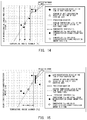
- FIG. 9 is a graph showing relation between the temperature inside the laser scanner and the color misregistration amount. This graph shows the relation after turning on the power source of the image forming apparatus 100 after leaving the image forming apparatus 100 for about 15 hours at a constant temperature after the use of the image forming apparatus 100 .
- a square represents the relation between the temperature inside the laser scanner immediately after turning on the power source and the color misregistration amount.
- a circle represents the relation between the temperature inside the laser scanner when performing the job and the color misregistration amount. Relational equation between the temperature inside the laser scanner and the color misregistration amount immediately after turning on the power source is different from that when performing the job.
- the prediction equation of the color misregistration used in the job at another point of time is similarly used in the job after leaving the image forming apparatus 100 unoperated for a long time, prediction error according to the difference of the internal state is generated.
- the auto registration is performed in the pre-operation of the job immediately after leaving the image forming apparatus 100 for a long time, downtime increases.
- the image forming apparatus 100 according to the present embodiment performs the color misregistration correction (auto registration) while suppressing the occurrence of the downtime. Embodiments will be described in the following.
- FIG. 10 is a flow chart showing processing from a start of a job to a calculation of a correction value.
- overtime job is a job which is performed after an elapsed time ⁇ t since the previous job is finished has elapsed predetermined time threshold tth or more.
- a “normal job” is a job other than the overtime job.
- Tout represents the detection result of the current temperature sensor 601 (temperature outside the apparatus).
- Tscn represents the detection result of the current temperature sensor 602 (temperature inside the laser scanner).
- X represents the color misregistration correction value.
- a suffix attached to a left side of each symbol represents a value stored in the memory 705 .
- areg represents a value stored at the time of the previous auto registration.
- m1areg represents a value stored at the time of the auto registration during the previous overtime job.
- m1aregTout represents the detection result of the temperature sensor 601 (temperature outside the apparatus) when the auto registration is performed before the image is formed on the basis of the previous overtime job.
- the temperature outside the apparatus m1aregTout is stored in the memory 705 .
- the CPU 703 When receiving the print job (Step S 101 ), the CPU 703 obtains the current time t, the temperature outside the apparatus Tout which is the detection result of the temperature sensor 601 , and the temperature inside the laser scanner Tscn which is the detection result of the temperature sensor 602 (Step S 102 ). The CPU 703 obtains the elapsed time ⁇ t since the previous job is finished from the current time t and the time prevt at which the previous job is finished (Step S 103 ). The CPU 703 determines whether the elapsed time ⁇ t is the time threshold tth or more or not (Step S 104 ). It means that the CPU 703 determines whether the elapsed time from the previous image formation is a predetermined time or longer or not.
- Step S 104 determines whether the correction value m1aregX, the temperature outside the apparatus m1aregTout, and the temperature inside the laser scanner m1aregTscn in the memory 705 are cleared or not (Step S 106 ).
- the CPU 703 determines that the correction value m1aregX, the temperature outside the apparatus m1aregTout, and the temperature inside the laser scanner m1aregTscn are cleared if the correction value is an initial value and the temperature is an initial temperature.
- Step S 106 the CPU 703 determines whether or not an absolute value of a temperature difference between the current temperature outside the apparatus Tout and the temperature outside the apparatus m1aregTout when performing the auto registration in the previous overtime job is smaller than the temperature threshold value Tth (Step S 107 ).
- the CPU 703 determines whether a temperature difference between the temperature outside the apparatus Tout detected before the image forming operation after the image forming apparatus 100 is left unoperated for a predetermined time or longer this time and the temperature outside the apparatus m1aregTout detected before the image forming operation after the image forming apparatus 100 is left unoperated for a predetermined time or longer previously is less than a predetermined temperature or not. It means that the CPU 703 determines whether or not the detected temperature at the time of the pre-operation this time is changed by a predetermined temperature or more from the detected temperature at the time of the previous pre-operation.
- Step S 106 if it is determined that the correction value m1aregX, the temperature outside the apparatus m1aregTout, and the temperature inside the laser scanner m1aregTscn are cleared (Step S 106 : Y), the CPU 703 performs the auto registration in the pre-operation (Step S 108 ). Moreover, if the absolute value of the temperature difference between the temperature outside the apparatus Tout and the temperature outside the apparatus m1aregTout is the temperature threshold Tth or more (Step S 107 : N), the CPU 703 performs the auto registration in the pre-operation (Step S 108 ).
- the CPU 703 also performs the auto registration in the pre-operation even in a case where the temperature difference between the temperature outside the apparatus Tout and the temperature outside the apparatus m1aregTout is a predetermined temperature or more. This is because it is likely that the current color misregistration is different from the color misregistration in the previous pre-operation.
- X0 is an initial value of the correction value, which is a predetermined value.
- the CPU 703 updates a value to be stored in the memory 705 to a value calculated by a following equation (3) by performing the auto registration during the overtime job (Step S 109 ). After updating the value, the CPU 703 calculates the correction value X by the normal job (Step S 105 ).
- Step S 107 if it is determined that the absolute value of the temperature difference between the temperature outside the apparatus Tout and the temperature outside the apparatus m1aregTout is less than the temperature threshold value Tth (Step S 107 : Y), the CPU 703 updates a value to be stored in the memory 705 to a value calculated by a following equation (4) when performing the auto registration (Step S 110 ).
- aregX m1aregX
- aregTout m1aregTout
- gTscn m1aregTscn Equation (4)
- the CPU 703 calculates the correction value X using a following equation (5) (Step S 111 ).
- the CPU 703 calculates the correction value X from the current temperature inside the laser scanner Tscn, the temperature inside the laser scanner m1aregTscn at the time of the auto registration during the previous overtime job, and the correction value m1aregX at the time of the auto registration during the previous overtime job.
- ⁇ 1 is a predetermined coefficient.
- the equation (5) is a prediction equation of the thermal shift.
- the color misregistration correction value X is calculated by either the normal job or the overtime job.
- the CPU 703 reflects the calculated correction value X to correct the respective control timing and performs the image forming processing according to the print job (Step S 112 , Step S 113 ).
- the coefficient ⁇ 2 used in the equation (1) and the coefficient ⁇ 1 used in the equation (5) are coefficients of the prediction equation of the thermal shift, which are experimentally derived.
- the image forming apparatus 100 according to the present embodiment is so configured that the temperature sensor 601 detects the temperature outside the apparatus Tout, but the temperature sensor 601 may detect a temperature outside the laser scanner 200 (temperature outside the laser scanner). In this case, a term of the temperature outside the apparatus used in the prediction equation may be replaced by the temperature outside the laser scanner.
- the CPU 703 may determine whether to perform the auto registration or not on the basis of a comparison result of the current temperature outside the laser scanner and a reference temperature of the temperature outside the laser scanner stored in the memory 705 .
- the detection temperature used for the prediction and determination of the job is not limited to the temperature outside the apparatus but may be used in combination with the temperature of the substrate of the laser scanner 200 and the like.
- the current temperature inside the laser scanner Tscn and the temperature inside the laser scanner m1aregTscn at the time of the auto registration during the previous overtime job may be used.
- the CPU 703 performs the auto registration in the pre-operation of the job.
- the color misregistration correction value X is calculated by applying the prediction equation dedicated to predict the color misregistration amount to a job such as the overtime job immediately after leaving the image forming apparatus 100 for a long time, in which the relational equation between the color misregistration amount and the temperature of the overtime job is different from that at performing timing of the other jobs.
- FIG. 11 shows relation between the correction residual and the temperature when performing the auto registration.
- a case of performing three types of color misregistration corrections in particular, performing the correction of the equation (1) for the normal job, performing the correction of the equation (1) for the overtime job, and performing the correction of the equation (5) for the overtime job, will be described.
- FIG. 11 shows that, regardless of a type of prediction equation, correction accuracy is significantly improved by performing the correction by the overtime job compared with the case of performing the correction by the normal job.
- the correction using the equation (5) reduces an inclination of the relational equation between the correction residual and the temperature to approximately half with respect to the correction using equation (1).
- a temperature range which needs no auto registration in the pre-operation is doubled with respect to color misregistration tolerance.
- the temperature threshold Tth is approximately equal to 3° C. (temperature threshold Tth ⁇ 3° C.)
- the temperature threshold Tth is approximately equal to 6° C. (temperature threshold value Tth ⁇ 6° C.).
- the image forming apparatus 100 of the present embodiment is capable of reducing the downtime due to the auto registration in the pre-operation while maintaining the performance of the color misregistration correction after leaving the image forming apparatus 100 for a long time by switching to perform the two correction patterns of the overtime job and the normal job. Further, by separately using the prediction equation for predicting the color misregistration amount in the overtime job and the normal job, it is possible to accurately perform the color misregistration correction.
- FIG. 12 is a flow chart showing processing from a start of a job to a calculation of a correction value according to a second embodiment.
- the processing from the step S 101 to the step S 113 is the same processing as the processing of the first embodiment shown in FIG. 10 .
- the CPU 703 determines whether the absolute value of the temperature difference between the current temperature outside the apparatus Tout and the temperature outside the apparatus m1aregTout is smaller than the temperature threshold Tth2 or not (Step S 115 ).
- the temperature threshold value Tth2 is set to a value smaller than the temperature threshold Tth.
- Step S 115 Y
- the CPU 703 performs the processing of the step S 114 . If it is determined that the absolute value of the temperature difference between the current temperature outside the apparatus Tout and the temperature outside the apparatus m1aregTout is the temperature threshold Tth2 or more (Step S 115 : N), the CPU 703 performs the auto registration in a post-operation after the print job is performed (Step S 116 ).
- the “post-processing” is a preliminary operation required to finish the image formation.
- the CPU 703 updates a value to be stored in the memory 705 to a value calculated by the equation (2) when performing the auto registration. Thereafter, the CPU 703 updates a value to be stored in the memory 705 to a value calculated by the equation (3) (Step S 117 ) and performs the processing of the step S 114 .
- the detection temperature used for the prediction and the determination of the job is not limited to the temperature outside the apparatus, but may also be used in combination with the temperature of the substrate of the laser scanner 200 and the like.
- the current temperature inside the laser scanner Tscn and the temperature inside the laser scanner m1aregTscn when performing the auto registration during the previous overtime job may be used.
- the internal state of the image forming apparatus 100 is not similar to the internal state of the image forming apparatus 100 at the time of the previous overtime job.
- the temperature outside the apparatus greatly differs depending on a day such as at the time of a change of season or an environment in which the temperature outside the apparatus is not stable due to air conditioning control and the like
- the temperature outside the apparatus at the time of the daily overtime job is unstable. Since the temperature outside the apparatus is unstable, the temperature inside the apparatus is unstable. This is why the internal state of the image forming apparatus 100 is not similar to the internal state at the time of the previous overtime job.
- the image forming apparatus 100 which is installed in an environment in which the temperature outside the apparatus greatly varies at the time of the daily overtime job is configured not to perform the color misregistration correction on the basis of the value stored in the memory 705 at the time of the overtime job.
- FIG. 13 is a flow chart showing processing from a start of a job to a calculation of a correction value according to a third embodiment.
- the processing in the step S 101 to the step S 104 is the same processing as the first embodiment shown in FIG. 10 .
- a suffix attached to a left side of each symbol represents a value stored in the memory 705 .
- “m1areg” represents a value stored at the time of the auto registration during the previous overtime job. The number included in “m1areg” indicates that it is a value at the time of the auto registration earlier than that number.
- m1aregTout represents the detection result of the temperature sensor 601 (temperature outside the apparatus) stored one time before, that is, at the time of the auto registration during the previous overtime job.
- “ave” represents an average value of the values stored at the time of the auto registration during the overtime jobs for the past several times. It should be noted that, in this embodiment, the average value of the values for the past three times is described as an example, but it is not limited to the past three times as long as it is multiple times.
- Step S 104 If it is determined that the elapsed time ⁇ t is less than the time threshold tth in the step S 104 (Step S 104 : N), the CPU 703 performs the processing as the normal job and performs the processing of the step S 105 . If it is determined that the elapsed time ⁇ t is the time threshold tth or more in the processing of the step S 104 (Step S 104 : Y), the CPU 703 performs the processing of the overtime job. The CPU 703 determines whether the results of the auto registration at the time of the overtime job for the past few times (in the present embodiment, three times) stored in the memory 705 are cleared or not (Step S 201 ).
- Step S 201 the CPU 703 calculates the average value of the values of the results of the auto registration at the time of the overtime job for the past three times (Step S 202 ).
- the CPU 703 calculates an average value aveTout of the temperatures outside the apparatus m1aregTout, m2aregTout and m3aregTout.
- the CPU 703 calculates an average value aveTscn of the temperatures inside the laser scanner m1aregTscn, m2aregTscn and m3aregTscn.
- the CPU 703 calculates an average value aveX of the correction values m1aregX, m2aregX and m3aregX.
- the CPU 703 determines whether variation in the temperatures inside the laser scanner for the past three times, m1aregTscn, m2aregTscn and m3aregTscn, is within a predetermined range or not (Step S 203 ).
- the CPU 703 determines whether the temperature difference between each of the temperatures inside the laser scanner for the past three times, m1aregTscn, m2aregTscn and m3aregTscn and the average value aveTout is smaller than the temperature threshold Tth1 or not. It means that the CPU 703 determines whether the temperature difference between a plurality of temperatures inside the laser scanner and their average value is less than a predetermined temperature or not.
- the CPU 703 determines that the variation in the temperatures inside the laser scanner m1aregTscn, m2aregTscn, and m3aregTscn is within a predetermined range (less than a predetermined temperature) (Step S 203 : Y). In this case, the CPU 703 determines whether the absolute value of the temperature difference between the average value aveTout of the temperatures inside the laser scanner and the current temperature inside the laser scanner Tscn is smaller than the temperature threshold value Tth2 or not (Step S 204 ).
- Step S 201 If it is determined that the results of the auto registration in the memory 705 are cleared (Step S 201 : Y), the CPU 703 performs the processing of the step S 108 .
- the CPU 703 also performs the processing of the step S 108 even in a case where the variation in the temperature inside the laser scanner is not within a predetermined range (Step S 203 : N), that is, in a case where the temperature difference is a predetermined temperature or more.
- the CPU 703 also performs the processing of the step S 108 if the absolute value of the temperature difference between the average value aveTout and the temperature inside the laser scanner Tscn is the temperature threshold Tth2 or more (Step S 204 : N).
- the CPU 703 updates a value to be stored in the memory 705 to a value to be calculated by a following equation (6) when performing the auto registration in the overtime job (Step S 207 ).
- the CPU 703 discards the results of the auto registration prior to the past three times when updating the value in the memory 705 . Thereafter, the CPU 703 performs the processing of the step S 105 .
- Step S 204 If it is determined that the absolute value of the temperature difference between the average value aveTout and the temperature inside the laser scanner Tscn is less than the temperature threshold Tth2 (Step S 204 : N), the CPU 703 updates a value to be stored in the memory 705 to a value calculated by a following equation (7) when performing the auto registration (Step S 205 ).
- the CPU 703 calculates the correction value X from the current temperature inside the laser scanner Tscn, the average value aveTscn of the temperatures inside the laser scanner, and the average value aveX of the correction values using an equation (8) (Step S 206 ).
- the equation (8) is a prediction equation of the thermal shift.
- the correction value X calculated here is a predicted value.
- the CPU 703 performs the same processing as the steps S 112 to S 114 of the first embodiment shown in FIG. 10 and finishes the processing.
- X ⁇ 1( Tscn ⁇ aveTscn )+ aveX Equation (8)
- FIG. 14 and FIG. 15 are diagrams each explaining color misregistration prediction propriety determination of the overtime job.
- the color misregistration prediction propriety determination of the overtime job is performed by determining whether the variation in the temperatures inside the laser scanner m1aregTscn, m2 aregTscn and m3aregTscn of the processing of the step S 203 is within a predetermined range or not.
- FIG. 14 and FIG. 15 show relation between the temperature inside the laser scanner and a color misregistration change (prediction) amount in the overtime job or in the result of the auto registration performed in the overtime job.
- the image-writing start timing by the laser scanner 200 is adjusted according to the color misregistration change prediction amount.
- a circle represents relation between the temperatures inside the laser scanner m1aregTscn, m2aregTscn, and m3aregTscn and the color misregistration change amount at the time of the auto registration performed in the overtime job for the past three times.
- An asterisk represents relation between the average value aveTscn and the average value aveX.
- aveTscn represents the average value of the temperatures inside the laser scanner m1aregTscn, m2aregTscn, and m3aregTscn.
- aveX represents the average value of the color misregistration change amounts.
- Inside of a solid line frame represents an area where the difference between the temperature inside laser scanner of the past and its average value aveTscn is within the temperature threshold Tth1.
- a black diamond represents relation between the temperature inside the laser scanner Tscn and the actual color misregistration change amount in the overtime job this time.
- a white diamond represents relation between the temperature inside the laser scanner Tscn and the color misregistration change prediction amount X this time. This is predicted on the basis of the average value aveTscn of the temperatures inside the laser scanner and the average value aveX of the color misregistration change amounts using the temperature inside the laser scanner Tscn and the prediction equation in the overtime job this time.
- the temperatures inside the laser scanner m1aregTscn, m2aregTscn, and m3aregTscn which are the results of the auto registration at the time of the overtime job for the past three times fall in the region in the solid line frame. In this case, it is considered that the internal state at the time of the overtime job for the past three times is stable and similar. Therefore, the CPU 703 determines that it is possible to predict the color misregistration amount.
- FIG. 14 the temperatures inside the laser scanner m1aregTscn, m2aregTscn, and m3aregTscn which are the results of the auto registration at the time of the overtime job for the past three times fall in the region in the solid line frame. In this case, it is considered that the internal state at the time of the overtime job for the past three times is stable and similar. Therefore, the CPU 703 determines that it is possible to predict the color misregistration amount.
- FIG. 14 the temperatures inside the laser scanner m1aregTsc
- the temperature used for the prediction and the determination of the job is not limited to the temperature inside the laser scanner, but may also be used in combination with the temperature outside the apparatus, the temperature of the substrate of the laser scanner 200 and the like.
- the current temperature outside the apparatus Tout and the average value aveTout of the temperatures outside the apparatus may be used.
- the temperature outside the apparatus Tout and the temperature near the outside the apparatus such as the temperature on the substrate of the laser scanner 200 have good responsiveness to the change of the temperature outside the apparatus so that, by using the temperature to determine the job, it is possible to determine with high accuracy that the internal state is not similar.
- FIG. 16 is a flow chart showing processing from a start of a job to a calculation of a correction value according to a fourth embodiment.
- the processing of the steps S 101 to S 105 , S 108 , S 201 to S 207 is the same processing as the processing of the third embodiment shown in FIG. 13 .
- the CPU 703 determines whether the absolute value of the temperature difference between the temperature inside the laser scanner Tscn and the average value aveTscn of the temperatures inside the laser scanner is smaller than temperature threshold Tth3 or not (Step S 208 ).
- the temperature threshold Tth3 is set to a value smaller than the temperature threshold Tth2 and stored in the storage region 7060 of the memory 705 .
- Step S 208 : Y If it is determined that the absolute value of the temperature difference between the temperatures inside the laser scanner is smaller than the temperature threshold Tth3 (Step S 208 : Y), the CPU 703 performs the processing of the step S 114 . If it is determined that the absolute value of the temperature difference between the temperatures inside the laser scanner is the temperature threshold Tth3 or more (Step S 208 : N), the CPU 703 performs the auto registration in the post-operation of the print job by the same processing as the processing of the step S 116 of the first embodiment (Step S 209 ). Thereafter, the CPU 703 updates a value to be stored in the memory 705 to a value calculated by the equation (6) and performs the processing of the step S 114 .
- the detection temperature used for the prediction and the determination of the job is not limited to the temperature inside the laser scanner, but may also be used in combination with the temperature outside the apparatus, the temperature of the substrate of the laser scanner 200 and the like.
- the current temperature outside the apparatus Tout and the average value aveTout of the temperatures outside the apparatus may be used.
- the number of times to perform the auto registration in the pre-operation by the processing of the step S 108 can be reduced. This realizes the further reduction of the downtime.
- the image forming apparatus 100 of the present disclosure is capable of reducing the downtime by reducing the frequency to perform the auto registration.
Landscapes
- Physics & Mathematics (AREA)
- General Physics & Mathematics (AREA)
- Engineering & Computer Science (AREA)
- Microelectronics & Electronic Packaging (AREA)
- Color Electrophotography (AREA)
- Control Or Security For Electrophotography (AREA)
Abstract
Description
Color Misregistration Amount in the Sub-Scanning Direction=(MR1′−YR1)−(MR1−YR1)=MR1′−MR1
Color misregistration amount in the sub-scanning direction={(MR3′−YR3)−(MR4′−YR4)}/2
Color misregistration amount in the main scanning direction={(MR3′−YR3)−(MR4′−YR4)}/2 tan θ
X=α2×(Tscn−aregTscn)+aregX Equation (1)
aregX=X0
aregTout=Tout
aregTscn=Tscn Equation (2)
m1aregX=aregX
m1aregTout=aregTout
m1aregTscn=aregTscn Equation (3)
aregX=m1aregX
aregTout=m1aregTout
aregTscn=m1aregTscn Equation (4)
X=α1×(Tscn−m1aregTscn)+m1aregX Equation (5)
prevt=t Equation (6)
m1aregX=aregX
m1aregTout=aregTout
m1aregTscn=aregTscn
m2aregX=m1aregX
m2aregTout=m1aregTout
m2aregTscn=m1aregTscn
m3aregX=m2aregX
m3aregTout=m2aregTout
m3aregTscn=m2aregTscn Equation (6)
aregX=aveX
aregTout=aveTout
aregTscn=aveTscn Equation (7)
X=α1(Tscn−aveTscn)+aveX Equation (8)
Claims (6)
Applications Claiming Priority (3)
| Application Number | Priority Date | Filing Date | Title |
|---|---|---|---|
| JP2018-169153 | 2018-09-10 | ||
| JP2018169153A JP7195828B2 (en) | 2018-09-10 | 2018-09-10 | image forming device |
| JPJP2018-169153 | 2018-09-10 |
Publications (2)
| Publication Number | Publication Date |
|---|---|
| US20200081390A1 US20200081390A1 (en) | 2020-03-12 |
| US10935919B2 true US10935919B2 (en) | 2021-03-02 |
Family
ID=69720754
Family Applications (1)
| Application Number | Title | Priority Date | Filing Date |
|---|---|---|---|
| US16/561,869 Active US10935919B2 (en) | 2018-09-10 | 2019-09-05 | Image forming apparatus |
Country Status (3)
| Country | Link |
|---|---|
| US (1) | US10935919B2 (en) |
| JP (1) | JP7195828B2 (en) |
| CN (1) | CN110888307A (en) |
Citations (11)
| Publication number | Priority date | Publication date | Assignee | Title |
|---|---|---|---|---|
| US7978995B2 (en) * | 2006-08-21 | 2011-07-12 | Konica Minolta Business Technologies, Inc. | Image forming apparatus for image density adjustment |
| US8107833B2 (en) | 2005-11-11 | 2012-01-31 | Ricoh Company, Ltd. | Image forming apparatus and method of correcting color misregistration in image forming apparatus |
| US8175474B2 (en) * | 2008-05-27 | 2012-05-08 | Canon Kabushiki Kaisha | Image forming apparatus with dynamic characteristic calculation |
| US8958730B2 (en) * | 2012-09-06 | 2015-02-17 | Canon Kabushiki Kaisha | Image forming apparatus |
| US9091987B2 (en) * | 2012-09-12 | 2015-07-28 | Ricoh Company, Limited | Image forming apparatus and image forming apparatus control method |
| US9141017B2 (en) * | 2013-02-19 | 2015-09-22 | Canon Kabushiki Kaisha | Image forming apparatus |
| US9291932B2 (en) * | 2011-12-01 | 2016-03-22 | Canon Kabushiki Kaisha | Image forming apparatus having misregistration correction |
| US9310705B2 (en) * | 2012-08-02 | 2016-04-12 | Canon Kabushiki Kaisha | Color image forming apparatus |
| US10073403B2 (en) * | 2016-05-26 | 2018-09-11 | Oki Data Corporation | Image formation apparatus that executes misregistration correction |
| US10254699B2 (en) * | 2016-08-12 | 2019-04-09 | Canon Kabushiki Kaisha | Image forming apparatus to correct timing of image formation |
| US10341502B2 (en) * | 2016-10-11 | 2019-07-02 | Canon Kabushiki Kaisha | Image forming apparatus that executes image processing corresponding to resolution |
Family Cites Families (12)
| Publication number | Priority date | Publication date | Assignee | Title |
|---|---|---|---|---|
| JP4622206B2 (en) | 2001-11-09 | 2011-02-02 | 富士ゼロックス株式会社 | Color image forming apparatus |
| JP4468798B2 (en) | 2003-12-19 | 2010-05-26 | 株式会社リコー | Color image forming apparatus |
| JP4488205B2 (en) | 2004-11-30 | 2010-06-23 | 株式会社リコー | Image forming apparatus |
| JP2007101721A (en) | 2005-09-30 | 2007-04-19 | Kyocera Mita Corp | Image forming apparatus |
| JP2007182018A (en) | 2006-01-10 | 2007-07-19 | Canon Inc | Image forming apparatus |
| JP2008009107A (en) | 2006-06-29 | 2008-01-17 | Ricoh Co Ltd | Image forming apparatus |
| JP4596048B2 (en) | 2008-06-20 | 2010-12-08 | コニカミノルタビジネステクノロジーズ株式会社 | Image forming apparatus and preparation operation execution method |
| JP2010102122A (en) | 2008-10-23 | 2010-05-06 | Konica Minolta Business Technologies Inc | Image forming apparatus, control method and control program |
| JP6436609B2 (en) | 2012-09-06 | 2018-12-12 | キヤノン株式会社 | Image forming apparatus |
| JP6306925B2 (en) | 2014-04-08 | 2018-04-04 | キヤノン株式会社 | Image forming apparatus |
| JP2015215512A (en) | 2014-05-12 | 2015-12-03 | キヤノン株式会社 | Image forming apparatus |
| JP6469067B2 (en) | 2016-11-18 | 2019-02-13 | キヤノン株式会社 | Image forming apparatus |
-
2018
- 2018-09-10 JP JP2018169153A patent/JP7195828B2/en active Active
-
2019
- 2019-09-05 CN CN201910834297.4A patent/CN110888307A/en not_active Withdrawn
- 2019-09-05 US US16/561,869 patent/US10935919B2/en active Active
Patent Citations (11)
| Publication number | Priority date | Publication date | Assignee | Title |
|---|---|---|---|---|
| US8107833B2 (en) | 2005-11-11 | 2012-01-31 | Ricoh Company, Ltd. | Image forming apparatus and method of correcting color misregistration in image forming apparatus |
| US7978995B2 (en) * | 2006-08-21 | 2011-07-12 | Konica Minolta Business Technologies, Inc. | Image forming apparatus for image density adjustment |
| US8175474B2 (en) * | 2008-05-27 | 2012-05-08 | Canon Kabushiki Kaisha | Image forming apparatus with dynamic characteristic calculation |
| US9291932B2 (en) * | 2011-12-01 | 2016-03-22 | Canon Kabushiki Kaisha | Image forming apparatus having misregistration correction |
| US9310705B2 (en) * | 2012-08-02 | 2016-04-12 | Canon Kabushiki Kaisha | Color image forming apparatus |
| US8958730B2 (en) * | 2012-09-06 | 2015-02-17 | Canon Kabushiki Kaisha | Image forming apparatus |
| US9091987B2 (en) * | 2012-09-12 | 2015-07-28 | Ricoh Company, Limited | Image forming apparatus and image forming apparatus control method |
| US9141017B2 (en) * | 2013-02-19 | 2015-09-22 | Canon Kabushiki Kaisha | Image forming apparatus |
| US10073403B2 (en) * | 2016-05-26 | 2018-09-11 | Oki Data Corporation | Image formation apparatus that executes misregistration correction |
| US10254699B2 (en) * | 2016-08-12 | 2019-04-09 | Canon Kabushiki Kaisha | Image forming apparatus to correct timing of image formation |
| US10341502B2 (en) * | 2016-10-11 | 2019-07-02 | Canon Kabushiki Kaisha | Image forming apparatus that executes image processing corresponding to resolution |
Also Published As
| Publication number | Publication date |
|---|---|
| JP7195828B2 (en) | 2022-12-26 |
| JP2020042152A (en) | 2020-03-19 |
| CN110888307A (en) | 2020-03-17 |
| US20200081390A1 (en) | 2020-03-12 |
Similar Documents
| Publication | Publication Date | Title |
|---|---|---|
| US9207611B2 (en) | Image forming apparatus and control method thereof | |
| US10126689B2 (en) | Image forming apparatus | |
| US11494602B2 (en) | Image forming apparatus | |
| JP2015028597A (en) | Image forming apparatus | |
| JP2008180948A (en) | Image forming method and image forming apparatus | |
| JP2018130968A (en) | Image formation apparatus, adjustment method for formation condition, and adjustment program for formation condition | |
| WO2011096087A1 (en) | Image formation device | |
| JP2018084617A (en) | Image forming apparatus and color misregistration adjustment method for image forming apparatus | |
| US10935919B2 (en) | Image forming apparatus | |
| JP2010107539A (en) | Color image forming apparatus | |
| JP6932485B2 (en) | Image forming device | |
| JP6292960B2 (en) | Image forming apparatus | |
| US10732558B2 (en) | Image forming apparatus | |
| JP2010072325A (en) | Image forming apparatus and optical scanner | |
| JP6584580B2 (en) | Image forming apparatus | |
| JP4597062B2 (en) | Beam scanning apparatus, image forming apparatus, timing correction method, and timing correction program | |
| JP2021071698A (en) | Image forming apparatus | |
| JP6156072B2 (en) | Image forming apparatus | |
| US11086271B2 (en) | Image forming apparatus determining color misregistration based on various temperatures | |
| JP2024031310A (en) | image forming device | |
| US9285743B2 (en) | Image forming apparatus | |
| JP6349883B2 (en) | Image forming apparatus, forming condition adjusting method, and forming condition adjusting program | |
| JP2016177197A (en) | Image formation device and image formation method | |
| JP2004144876A (en) | Optical scanning device and image forming apparatus | |
| JP2011197137A (en) | Image forming apparatus, image forming method, and program of the same |
Legal Events
| Date | Code | Title | Description |
|---|---|---|---|
| FEPP | Fee payment procedure |
Free format text: ENTITY STATUS SET TO UNDISCOUNTED (ORIGINAL EVENT CODE: BIG.); ENTITY STATUS OF PATENT OWNER: LARGE ENTITY |
|
| AS | Assignment |
Owner name: CANON KABUSHIKI KAISHA, JAPAN Free format text: ASSIGNMENT OF ASSIGNORS INTEREST;ASSIGNORS:HAMANO, AKIRA;ISHIKAWA, RIN;TSUJIMURA, TAKASHI;AND OTHERS;SIGNING DATES FROM 20191220 TO 20200302;REEL/FRAME:052240/0887 |
|
| STPP | Information on status: patent application and granting procedure in general |
Free format text: DOCKETED NEW CASE - READY FOR EXAMINATION |
|
| STCF | Information on status: patent grant |
Free format text: PATENTED CASE |
|
| MAFP | Maintenance fee payment |
Free format text: PAYMENT OF MAINTENANCE FEE, 4TH YEAR, LARGE ENTITY (ORIGINAL EVENT CODE: M1551); ENTITY STATUS OF PATENT OWNER: LARGE ENTITY Year of fee payment: 4 |