US10934915B2 - Internal combustion engine - Google Patents
Internal combustion engine Download PDFInfo
- Publication number
- US10934915B2 US10934915B2 US16/326,414 US201716326414A US10934915B2 US 10934915 B2 US10934915 B2 US 10934915B2 US 201716326414 A US201716326414 A US 201716326414A US 10934915 B2 US10934915 B2 US 10934915B2
- Authority
- US
- United States
- Prior art keywords
- urea
- water solution
- filter
- internal combustion
- combustion engine
- Prior art date
- Legal status (The legal status is an assumption and is not a legal conclusion. Google has not performed a legal analysis and makes no representation as to the accuracy of the status listed.)
- Active
Links
Images


Classifications
-
- F—MECHANICAL ENGINEERING; LIGHTING; HEATING; WEAPONS; BLASTING
- F01—MACHINES OR ENGINES IN GENERAL; ENGINE PLANTS IN GENERAL; STEAM ENGINES
- F01N—GAS-FLOW SILENCERS OR EXHAUST APPARATUS FOR MACHINES OR ENGINES IN GENERAL; GAS-FLOW SILENCERS OR EXHAUST APPARATUS FOR INTERNAL-COMBUSTION ENGINES
- F01N3/00—Exhaust or silencing apparatus having means for purifying, rendering innocuous, or otherwise treating exhaust
- F01N3/08—Exhaust or silencing apparatus having means for purifying, rendering innocuous, or otherwise treating exhaust for rendering innocuous
- F01N3/10—Exhaust or silencing apparatus having means for purifying, rendering innocuous, or otherwise treating exhaust for rendering innocuous by thermal or catalytic conversion of noxious components of exhaust
- F01N3/18—Exhaust or silencing apparatus having means for purifying, rendering innocuous, or otherwise treating exhaust for rendering innocuous by thermal or catalytic conversion of noxious components of exhaust characterised by methods of operation; Control
- F01N3/20—Exhaust or silencing apparatus having means for purifying, rendering innocuous, or otherwise treating exhaust for rendering innocuous by thermal or catalytic conversion of noxious components of exhaust characterised by methods of operation; Control specially adapted for catalytic conversion
- F01N3/206—Adding periodically or continuously substances to exhaust gases for promoting purification, e.g. catalytic material in liquid form, NOx reducing agents
- F01N3/2066—Selective catalytic reduction [SCR]
-
- B—PERFORMING OPERATIONS; TRANSPORTING
- B01—PHYSICAL OR CHEMICAL PROCESSES OR APPARATUS IN GENERAL
- B01D—SEPARATION
- B01D19/00—Degasification of liquids
- B01D19/0031—Degasification of liquids by filtration
-
- B—PERFORMING OPERATIONS; TRANSPORTING
- B01—PHYSICAL OR CHEMICAL PROCESSES OR APPARATUS IN GENERAL
- B01D—SEPARATION
- B01D19/00—Degasification of liquids
- B01D19/0036—Flash degasification
-
- B—PERFORMING OPERATIONS; TRANSPORTING
- B01—PHYSICAL OR CHEMICAL PROCESSES OR APPARATUS IN GENERAL
- B01D—SEPARATION
- B01D19/00—Degasification of liquids
- B01D19/0063—Regulation, control including valves and floats
-
- B—PERFORMING OPERATIONS; TRANSPORTING
- B01—PHYSICAL OR CHEMICAL PROCESSES OR APPARATUS IN GENERAL
- B01D—SEPARATION
- B01D2239/00—Aspects relating to filtering material for liquid or gaseous fluids
- B01D2239/02—Types of fibres, filaments or particles, self-supporting or supported materials
- B01D2239/0208—Single-component fibres
-
- B—PERFORMING OPERATIONS; TRANSPORTING
- B01—PHYSICAL OR CHEMICAL PROCESSES OR APPARATUS IN GENERAL
- B01D—SEPARATION
- B01D2239/00—Aspects relating to filtering material for liquid or gaseous fluids
- B01D2239/06—Filter cloth, e.g. knitted, woven non-woven; self-supported material
- B01D2239/0604—Arrangement of the fibres in the filtering material
- B01D2239/0618—Non-woven
-
- B—PERFORMING OPERATIONS; TRANSPORTING
- B01—PHYSICAL OR CHEMICAL PROCESSES OR APPARATUS IN GENERAL
- B01D—SEPARATION
- B01D2239/00—Aspects relating to filtering material for liquid or gaseous fluids
- B01D2239/12—Special parameters characterising the filtering material
- B01D2239/1216—Pore size
-
- B—PERFORMING OPERATIONS; TRANSPORTING
- B01—PHYSICAL OR CHEMICAL PROCESSES OR APPARATUS IN GENERAL
- B01D—SEPARATION
- B01D29/00—Filters with filtering elements stationary during filtration, e.g. pressure or suction filters, not covered by groups B01D24/00 - B01D27/00; Filtering elements therefor
- B01D29/88—Filters with filtering elements stationary during filtration, e.g. pressure or suction filters, not covered by groups B01D24/00 - B01D27/00; Filtering elements therefor having feed or discharge devices
- B01D29/90—Filters with filtering elements stationary during filtration, e.g. pressure or suction filters, not covered by groups B01D24/00 - B01D27/00; Filtering elements therefor having feed or discharge devices for feeding
- B01D29/904—Filters with filtering elements stationary during filtration, e.g. pressure or suction filters, not covered by groups B01D24/00 - B01D27/00; Filtering elements therefor having feed or discharge devices for feeding directing the mixture to be filtered on the filtering element in a manner to clean the filter continuously
-
- B—PERFORMING OPERATIONS; TRANSPORTING
- B01—PHYSICAL OR CHEMICAL PROCESSES OR APPARATUS IN GENERAL
- B01D—SEPARATION
- B01D39/00—Filtering material for liquid or gaseous fluids
- B01D39/14—Other self-supporting filtering material ; Other filtering material
-
- B—PERFORMING OPERATIONS; TRANSPORTING
- B01—PHYSICAL OR CHEMICAL PROCESSES OR APPARATUS IN GENERAL
- B01D—SEPARATION
- B01D39/00—Filtering material for liquid or gaseous fluids
- B01D39/14—Other self-supporting filtering material ; Other filtering material
- B01D39/16—Other self-supporting filtering material ; Other filtering material of organic material, e.g. synthetic fibres
- B01D39/1607—Other self-supporting filtering material ; Other filtering material of organic material, e.g. synthetic fibres the material being fibrous
- B01D39/1615—Other self-supporting filtering material ; Other filtering material of organic material, e.g. synthetic fibres the material being fibrous of natural origin
-
- B—PERFORMING OPERATIONS; TRANSPORTING
- B01—PHYSICAL OR CHEMICAL PROCESSES OR APPARATUS IN GENERAL
- B01D—SEPARATION
- B01D39/00—Filtering material for liquid or gaseous fluids
- B01D39/14—Other self-supporting filtering material ; Other filtering material
- B01D39/20—Other self-supporting filtering material ; Other filtering material of inorganic material, e.g. asbestos paper, metallic filtering material of non-woven wires
- B01D39/2003—Glass or glassy material
- B01D39/2017—Glass or glassy material the material being filamentary or fibrous
-
- B—PERFORMING OPERATIONS; TRANSPORTING
- B01—PHYSICAL OR CHEMICAL PROCESSES OR APPARATUS IN GENERAL
- B01D—SEPARATION
- B01D39/00—Filtering material for liquid or gaseous fluids
- B01D39/14—Other self-supporting filtering material ; Other filtering material
- B01D39/20—Other self-supporting filtering material ; Other filtering material of inorganic material, e.g. asbestos paper, metallic filtering material of non-woven wires
- B01D39/2027—Metallic material
- B01D39/2031—Metallic material the material being particulate
- B01D39/2034—Metallic material the material being particulate sintered or bonded by inorganic agents
-
- B—PERFORMING OPERATIONS; TRANSPORTING
- B01—PHYSICAL OR CHEMICAL PROCESSES OR APPARATUS IN GENERAL
- B01D—SEPARATION
- B01D53/00—Separation of gases or vapours; Recovering vapours of volatile solvents from gases; Chemical or biological purification of waste gases, e.g. engine exhaust gases, smoke, fumes, flue gases, aerosols
- B01D53/34—Chemical or biological purification of waste gases
- B01D53/92—Chemical or biological purification of waste gases of engine exhaust gases
- B01D53/94—Chemical or biological purification of waste gases of engine exhaust gases by catalytic processes
- B01D53/9404—Removing only nitrogen compounds
- B01D53/9409—Nitrogen oxides
- B01D53/9431—Processes characterised by a specific device
-
- F—MECHANICAL ENGINEERING; LIGHTING; HEATING; WEAPONS; BLASTING
- F01—MACHINES OR ENGINES IN GENERAL; ENGINE PLANTS IN GENERAL; STEAM ENGINES
- F01N—GAS-FLOW SILENCERS OR EXHAUST APPARATUS FOR MACHINES OR ENGINES IN GENERAL; GAS-FLOW SILENCERS OR EXHAUST APPARATUS FOR INTERNAL-COMBUSTION ENGINES
- F01N2610/00—Adding substances to exhaust gases
- F01N2610/02—Adding substances to exhaust gases the substance being ammonia or urea
-
- F—MECHANICAL ENGINEERING; LIGHTING; HEATING; WEAPONS; BLASTING
- F01—MACHINES OR ENGINES IN GENERAL; ENGINE PLANTS IN GENERAL; STEAM ENGINES
- F01N—GAS-FLOW SILENCERS OR EXHAUST APPARATUS FOR MACHINES OR ENGINES IN GENERAL; GAS-FLOW SILENCERS OR EXHAUST APPARATUS FOR INTERNAL-COMBUSTION ENGINES
- F01N2610/00—Adding substances to exhaust gases
- F01N2610/10—Adding substances to exhaust gases the substance being heated, e.g. by heating tank or supply line of the added substance
-
- F—MECHANICAL ENGINEERING; LIGHTING; HEATING; WEAPONS; BLASTING
- F01—MACHINES OR ENGINES IN GENERAL; ENGINE PLANTS IN GENERAL; STEAM ENGINES
- F01N—GAS-FLOW SILENCERS OR EXHAUST APPARATUS FOR MACHINES OR ENGINES IN GENERAL; GAS-FLOW SILENCERS OR EXHAUST APPARATUS FOR INTERNAL-COMBUSTION ENGINES
- F01N2610/00—Adding substances to exhaust gases
- F01N2610/14—Arrangements for the supply of substances, e.g. conduits
- F01N2610/1406—Storage means for substances, e.g. tanks or reservoirs
-
- F—MECHANICAL ENGINEERING; LIGHTING; HEATING; WEAPONS; BLASTING
- F01—MACHINES OR ENGINES IN GENERAL; ENGINE PLANTS IN GENERAL; STEAM ENGINES
- F01N—GAS-FLOW SILENCERS OR EXHAUST APPARATUS FOR MACHINES OR ENGINES IN GENERAL; GAS-FLOW SILENCERS OR EXHAUST APPARATUS FOR INTERNAL-COMBUSTION ENGINES
- F01N2610/00—Adding substances to exhaust gases
- F01N2610/14—Arrangements for the supply of substances, e.g. conduits
- F01N2610/1426—Filtration means
-
- F—MECHANICAL ENGINEERING; LIGHTING; HEATING; WEAPONS; BLASTING
- F01—MACHINES OR ENGINES IN GENERAL; ENGINE PLANTS IN GENERAL; STEAM ENGINES
- F01N—GAS-FLOW SILENCERS OR EXHAUST APPARATUS FOR MACHINES OR ENGINES IN GENERAL; GAS-FLOW SILENCERS OR EXHAUST APPARATUS FOR INTERNAL-COMBUSTION ENGINES
- F01N2610/00—Adding substances to exhaust gases
- F01N2610/14—Arrangements for the supply of substances, e.g. conduits
- F01N2610/1433—Pumps
-
- F—MECHANICAL ENGINEERING; LIGHTING; HEATING; WEAPONS; BLASTING
- F01—MACHINES OR ENGINES IN GENERAL; ENGINE PLANTS IN GENERAL; STEAM ENGINES
- F01N—GAS-FLOW SILENCERS OR EXHAUST APPARATUS FOR MACHINES OR ENGINES IN GENERAL; GAS-FLOW SILENCERS OR EXHAUST APPARATUS FOR INTERNAL-COMBUSTION ENGINES
- F01N2610/00—Adding substances to exhaust gases
- F01N2610/14—Arrangements for the supply of substances, e.g. conduits
- F01N2610/1453—Sprayers or atomisers; Arrangement thereof in the exhaust apparatus
-
- F—MECHANICAL ENGINEERING; LIGHTING; HEATING; WEAPONS; BLASTING
- F01—MACHINES OR ENGINES IN GENERAL; ENGINE PLANTS IN GENERAL; STEAM ENGINES
- F01N—GAS-FLOW SILENCERS OR EXHAUST APPARATUS FOR MACHINES OR ENGINES IN GENERAL; GAS-FLOW SILENCERS OR EXHAUST APPARATUS FOR INTERNAL-COMBUSTION ENGINES
- F01N2610/00—Adding substances to exhaust gases
- F01N2610/14—Arrangements for the supply of substances, e.g. conduits
- F01N2610/1466—Means for venting air out of conduits or tanks
-
- F—MECHANICAL ENGINEERING; LIGHTING; HEATING; WEAPONS; BLASTING
- F01—MACHINES OR ENGINES IN GENERAL; ENGINE PLANTS IN GENERAL; STEAM ENGINES
- F01N—GAS-FLOW SILENCERS OR EXHAUST APPARATUS FOR MACHINES OR ENGINES IN GENERAL; GAS-FLOW SILENCERS OR EXHAUST APPARATUS FOR INTERNAL-COMBUSTION ENGINES
- F01N2610/00—Adding substances to exhaust gases
- F01N2610/14—Arrangements for the supply of substances, e.g. conduits
- F01N2610/1473—Overflow or return means for the substances, e.g. conduits or valves for the return path
-
- F—MECHANICAL ENGINEERING; LIGHTING; HEATING; WEAPONS; BLASTING
- F01—MACHINES OR ENGINES IN GENERAL; ENGINE PLANTS IN GENERAL; STEAM ENGINES
- F01N—GAS-FLOW SILENCERS OR EXHAUST APPARATUS FOR MACHINES OR ENGINES IN GENERAL; GAS-FLOW SILENCERS OR EXHAUST APPARATUS FOR INTERNAL-COMBUSTION ENGINES
- F01N2610/00—Adding substances to exhaust gases
- F01N2610/14—Arrangements for the supply of substances, e.g. conduits
- F01N2610/148—Arrangement of sensors
Definitions
- the present invention relates to an internal combustion engine including a urea-water solution injection in the exhaust system as well as a method for degasification and filtration.
- Degasification refers to removing gases and other volatile substances from liquids and solids in a controlled manner.
- the most commonly used method for degasification is to subject the material to be degassed to a vacuum. If ultrasound is introduced into a liquid, for example via a sonotrode, a high-frequency alternating pressure field is formed therein. The short-term negative pressure which is periodically formed results in cavities. This effect is referred to as cavitation.
- the cavities are formed at gas pockets, for example, which act as cavitation nuclei.
- the dissolved gas diffuses into the cavitation bubbles and prevents them from completely imploding during the subsequent pressure increase:
- the bubbles grow with every oscillation process. If standing waves are formed through reflections, the bubbles are pushed to their nodes, where they coalesce and ultimately migrate to the surface as a result of their buoyancy. Due to the temperature dependency of the Henry constant, a degasification may also be achieved solely by raising the temperature. The easiest possibility is to feed energy at decreased pressure and is referred to as boiling in vacuum. This effect may be observed during the normal boiling procedure; air bubbles forming in the water in this case.
- the present invention provides an internal combustion engine including a urea-water solution injection in the exhaust system, including at least one urea-water solution tank, at least one pump, at least one intake line leading to the pump, at least one urea-water solution metering valve which is connected to the pump with the aid of a pressure line, and at least one return line which leads from the pump to the urea-water solution tank and at whose end opposite to the pump a filter element is situated, as well as at least one urea-water solution sensor situated in the urea-water solution tank, and a method for degasification and filtration of the urea-water solution, in particular for use in an internal combustion engine.
- a urea-water solution injection in the exhaust system including at least one urea-water solution tank, at least one pump, at least one intake line leading to the pump, at least one urea-water solution metering valve which is connected to the pump with the aid of a pressure line, and at least one return line which leads from the pump to the urea
- the urea-water solution sensor measures the proportion of urea in the solution with water. This takes place, for example, by measuring the density with the aid of ultrasound or infrared measurement. Tiny bubbles in the measuring path of the sensor falsify the measuring result.
- the advantage of the present invention is the prevention or reduction of the entry of tiny bubbles (which have formed in the pump or in the lines, for example) into the urea-water solution tank, whereby suitable measuring conditions for the urea-water solution sensor are achieved.
- the filter is a precoat filter or a cartridge filter, or a spatial filter, or a multi-layer bed filter, or a magnetic filter.
- the filter includes flexible filter media or rigid filter media or packed beds.
- the filter material is a strainer or a paper filter or a glass fiber mat, or a ceramic, or a sintered metal, or a needle felt.
- the pore size of the filter is smaller than 70 micrometers.
- the filter is a two-dimensional filter or a three-dimensional filter or a multilayer filter or a surface filter or a depth filter.
- One advantageous refinement provides that the urea-water solution tank is subjected to a vacuum and/or is provided with venting additives.
- the urea-water solution tank includes an ultrasound generator and/or a heater, the ultrasound generator being situated in the quality sensor.
- FIG. 1 shows a schematic representation of the urea-water solution tank up to the injector
- FIG. 2 shows a schematic representation of the internal combustion engine including the urea-water solution tank and metering valve]
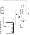
- FIG. 3 shows a variant of the representation in FIG. 2 including a return flow from the metering valve.
- FIG. 1 shows a schematic representation of urea-water solution tank 7 in which the urea water solution is contained and which includes a quality sensor 3 .
- urea-water solution tank 7 an intake line is situated at the one end of which a filter is situated and at the other end of which urea-water solution pump 6 is situated.
- a return line is also situated at the side of which opposite to the pump a filter 1 is situated which retains air bubbles.
- a pressure line runs from pump 6 to urea-water solution metering valve 8 .
- FIG. 2 a schematic representation of the internal combustion engine including urea-water solution tank 7 , engine control unit (ECU), urea-water solution pump 6 , and metering valve 8 which meters into the exhaust system is illustrated.
- Urea-water solution tank 7 includes a filter 1 at the return flow for bubble deposition, a filter 2 at the intake line, a quality sensor 3 , a fill level sensor 4 , and a temperature sensor 5 which are all connected to engine control unit (ECU) of internal combustion engine (ICE).
- ECU engine control unit
- ICE internal combustion engine
- a return line is also situated at the side of which opposite to pump 6 a filter 1 is situated which retains air bubbles.
- a pressure line runs from pump 6 controlled by engine control unit (ECU) to urea-water solution metering valve 8 which meters urea-water solution into the exhaust system and is also controlled by engine control unit (ECU) of internal combustion engine (ICE).
- ECU engine control unit
- FIG. 3 shows a schematic representation of the internal combustion engine including urea-water solution tank 7 , engine control unit (ECU), urea-water solution pump 6 , and metering valve 8 which meters into the exhaust system.
- Urea-water solution tank 7 includes a filter 1 at the return flow for bubble deposition, a filter 2 at the intake line, a quality sensor 3 , a fill level sensor 4 , and a temperature sensor 5 which are all connected to engine control unit (ECU) of internal combustion engine (ICE).
- ECU engine control unit
- ICE internal combustion engine
- a return line is also situated at the side of which opposite to pump 6 a filter 1 is situated which retains air bubbles.
- a pressure line runs from pump 6 controlled by engine control unit (ECU) to urea-water solution metering valve 8 which meters urea-water solution into the exhaust system and is also controlled by engine control unit (ECU) of internal combustion engine (ICE).
- ECU engine control unit
- ICE internal combustion engine
Landscapes
- Chemical & Material Sciences (AREA)
- Chemical Kinetics & Catalysis (AREA)
- Engineering & Computer Science (AREA)
- Health & Medical Sciences (AREA)
- Combustion & Propulsion (AREA)
- Toxicology (AREA)
- Mechanical Engineering (AREA)
- General Engineering & Computer Science (AREA)
- Exhaust Gas After Treatment (AREA)
- Life Sciences & Earth Sciences (AREA)
- Geology (AREA)
- Degasification And Air Bubble Elimination (AREA)
- Filtration Of Liquid (AREA)
- Exhaust Gas Treatment By Means Of Catalyst (AREA)
- Inorganic Chemistry (AREA)
- Biomedical Technology (AREA)
- Environmental & Geological Engineering (AREA)
- Analytical Chemistry (AREA)
- General Chemical & Material Sciences (AREA)
- Oil, Petroleum & Natural Gas (AREA)
Abstract
Description
- 1 filter at the return flow for bubble deposition
- 2 filter at the intake line
- 3 quality sensor
- 4 fill level sensor
- 5 temperature sensor
- 6 urea-water solution pump
- 7 urea-water solution tank
- 8 urea-water solution metering valve
- ECU engine control unit
- ICE internal combustion engine
Claims (14)
Applications Claiming Priority (3)
| Application Number | Priority Date | Filing Date | Title |
|---|---|---|---|
| DE102016010100.8 | 2016-08-24 | ||
| DE102016010100.8A DE102016010100B4 (en) | 2016-08-24 | 2016-08-24 | internal combustion engine |
| PCT/EP2017/000958 WO2018036647A2 (en) | 2016-08-24 | 2017-08-07 | Internal combustion engine |
Publications (2)
| Publication Number | Publication Date |
|---|---|
| US20190186320A1 US20190186320A1 (en) | 2019-06-20 |
| US10934915B2 true US10934915B2 (en) | 2021-03-02 |
Family
ID=59631715
Family Applications (1)
| Application Number | Title | Priority Date | Filing Date |
|---|---|---|---|
| US16/326,414 Active US10934915B2 (en) | 2016-08-24 | 2017-08-07 | Internal combustion engine |
Country Status (5)
| Country | Link |
|---|---|
| US (1) | US10934915B2 (en) |
| EP (1) | EP3504404A2 (en) |
| JP (1) | JP7083337B2 (en) |
| DE (1) | DE102016010100B4 (en) |
| WO (1) | WO2018036647A2 (en) |
Families Citing this family (1)
| Publication number | Priority date | Publication date | Assignee | Title |
|---|---|---|---|---|
| DE102021112195A1 (en) | 2021-05-11 | 2022-11-17 | Bayerische Motoren Werke Aktiengesellschaft | Method for reducing the accumulation of bubbles in a tank of a motor vehicle and exhaust gas aftertreatment device |
Citations (11)
| Publication number | Priority date | Publication date | Assignee | Title |
|---|---|---|---|---|
| US5832717A (en) | 1996-03-21 | 1998-11-10 | Societe Nationale D'etude Et De Construction De Moteurs D'aviation "Snecma" | Fuel injection supply circuit for providing a metered decontaminated flow of fuel to the fuel injectors |
| US20020081239A1 (en) | 2000-10-19 | 2002-06-27 | Hydraulik-Ring Gmbh | Device for exhaust gas after treatment of diesel engines |
| DE102007012918A1 (en) | 2007-03-19 | 2008-09-25 | Robert Bosch Gmbh | Controllable liquid valve operating method for increasing resistance of valve against freezing, involves initiating rest condition after delivery of liquid, and repeatedly opening and closing liquid valve at high frequency |
| WO2009118325A1 (en) | 2008-03-28 | 2009-10-01 | Inergy Automotive Systems Research (Société Anonyme) | SCR SYSTEM FOR PURIFYING EXHAUST GASES IN NOx |
| EP2206897A1 (en) | 2009-01-09 | 2010-07-14 | Robert Bosch GmbH | Supply device for a SCR system |
| DE102009029400A1 (en) | 2009-09-11 | 2011-03-24 | Robert Bosch Gmbh | Fuel tank for storing liquid, has main tank, inner tank and conveying device for conveying stored fluid from tank volume |
| WO2013029950A1 (en) | 2011-08-29 | 2013-03-07 | Inergy Automotive Systems Research (Société Anonyme) | Supply system for a liquid |
| EP2708710A2 (en) | 2012-09-13 | 2014-03-19 | TI Group Automotive Systems, L.L.C. | Fluid distribution system and components thereof |
| US20140166126A1 (en) | 2012-12-17 | 2014-06-19 | Deere & Company | Reductant delivery system |
| US20140334983A1 (en) * | 2013-05-07 | 2014-11-13 | Tenneco Automotive Operating Company Inc. | Reductant Sensor System |
| WO2016076830A1 (en) | 2014-11-10 | 2016-05-19 | Cummins Emission Solutions, Inc. | Exhaust fluid filter including hydrocarbon detection witness media |
Family Cites Families (5)
| Publication number | Priority date | Publication date | Assignee | Title |
|---|---|---|---|---|
| JP2000129311A (en) | 1998-10-28 | 2000-05-09 | Bridgestone Corp | Metallic fiber non-woven fabric sintered sheet |
| JP4214077B2 (en) | 2004-04-08 | 2009-01-28 | 日野自動車株式会社 | Urea water storage device |
| JP5381618B2 (en) | 2009-10-27 | 2014-01-08 | スズキ株式会社 | Scooter type motorcycle |
| JP6024478B2 (en) | 2013-01-28 | 2016-11-16 | いすゞ自動車株式会社 | Urea water pipe blockage detection device for urea SCR |
| US9089791B2 (en) * | 2013-03-14 | 2015-07-28 | Cummins Ip, Inc. | Apparatus, method, and system for reductant filtration |
-
2016
- 2016-08-24 DE DE102016010100.8A patent/DE102016010100B4/en active Active
-
2017
- 2017-08-07 JP JP2019510642A patent/JP7083337B2/en active Active
- 2017-08-07 EP EP17752287.7A patent/EP3504404A2/en not_active Withdrawn
- 2017-08-07 WO PCT/EP2017/000958 patent/WO2018036647A2/en not_active Ceased
- 2017-08-07 US US16/326,414 patent/US10934915B2/en active Active
Patent Citations (15)
| Publication number | Priority date | Publication date | Assignee | Title |
|---|---|---|---|---|
| US5832717A (en) | 1996-03-21 | 1998-11-10 | Societe Nationale D'etude Et De Construction De Moteurs D'aviation "Snecma" | Fuel injection supply circuit for providing a metered decontaminated flow of fuel to the fuel injectors |
| US20020081239A1 (en) | 2000-10-19 | 2002-06-27 | Hydraulik-Ring Gmbh | Device for exhaust gas after treatment of diesel engines |
| DE102007012918A1 (en) | 2007-03-19 | 2008-09-25 | Robert Bosch Gmbh | Controllable liquid valve operating method for increasing resistance of valve against freezing, involves initiating rest condition after delivery of liquid, and repeatedly opening and closing liquid valve at high frequency |
| US20110016853A1 (en) * | 2008-03-28 | 2011-01-27 | Inergy Automotive Systems Research (Societe Anonyme) | SCR system for purifying exhaust gases in NOx |
| WO2009118325A1 (en) | 2008-03-28 | 2009-10-01 | Inergy Automotive Systems Research (Société Anonyme) | SCR SYSTEM FOR PURIFYING EXHAUST GASES IN NOx |
| EP2206897A1 (en) | 2009-01-09 | 2010-07-14 | Robert Bosch GmbH | Supply device for a SCR system |
| DE102009000097A1 (en) | 2009-01-09 | 2010-07-15 | Robert Bosch Gmbh | Conveyor for an SCR system |
| DE102009029400A1 (en) | 2009-09-11 | 2011-03-24 | Robert Bosch Gmbh | Fuel tank for storing liquid, has main tank, inner tank and conveying device for conveying stored fluid from tank volume |
| WO2013029950A1 (en) | 2011-08-29 | 2013-03-07 | Inergy Automotive Systems Research (Société Anonyme) | Supply system for a liquid |
| EP2708710A2 (en) | 2012-09-13 | 2014-03-19 | TI Group Automotive Systems, L.L.C. | Fluid distribution system and components thereof |
| US20140166126A1 (en) | 2012-12-17 | 2014-06-19 | Deere & Company | Reductant delivery system |
| US20140334983A1 (en) * | 2013-05-07 | 2014-11-13 | Tenneco Automotive Operating Company Inc. | Reductant Sensor System |
| DE112014002334T5 (en) | 2013-05-07 | 2016-01-14 | Tenneco Automotive Operating Company Inc. | Reducing agent sensor system |
| US9752486B2 (en) | 2013-05-07 | 2017-09-05 | Tenneco Automotive Operating Company Inc. | Reductant sensor system |
| WO2016076830A1 (en) | 2014-11-10 | 2016-05-19 | Cummins Emission Solutions, Inc. | Exhaust fluid filter including hydrocarbon detection witness media |
Non-Patent Citations (1)
| Title |
|---|
| ISR of PCT/EP2017/000958, dated Feb. 16, 2018. |
Also Published As
| Publication number | Publication date |
|---|---|
| EP3504404A2 (en) | 2019-07-03 |
| WO2018036647A3 (en) | 2018-04-19 |
| US20190186320A1 (en) | 2019-06-20 |
| DE102016010100A1 (en) | 2018-03-01 |
| JP7083337B2 (en) | 2022-06-10 |
| JP2019532207A (en) | 2019-11-07 |
| DE102016010100B4 (en) | 2025-07-24 |
| WO2018036647A2 (en) | 2018-03-01 |
Similar Documents
| Publication | Publication Date | Title |
|---|---|---|
| CN105189965B (en) | Recirculating Exhaust Treatment Fluid Systems | |
| KR101462565B1 (en) | Monitoring method real-time fouling potential in Reverse Osmosis Process for Seawater Desalination and Desalination equipment having such monitoring function | |
| EP2573345B1 (en) | Scr system | |
| CN102791976B (en) | Urea quality diagnosis system | |
| KR20110018454A (en) | Drain device, fuel filter, fuel supply device, vehicle engine, vehicle, and liquid drain method | |
| CN104220741B (en) | For providing the filtration system of cleaning fuel | |
| US20120304626A1 (en) | Method for determining an amount of liquid removed from a tank and reducing agent supply device for a motor vehicle | |
| US10934915B2 (en) | Internal combustion engine | |
| CN102893004A (en) | NOx sensor diagnostic device and SCR system | |
| CN105556301B (en) | Vehicle urea tank associated with a sensing chamber for acoustic quality inspection and level sensing | |
| WO2015179432A1 (en) | Reduction of aeration interference via tortuous path and sensor boot | |
| DE102006013263A1 (en) | Liquid`s urea water solution concentration determining method for exhaust gas cleaning in motor vehicle, involves determining concentration of urea water solution in liquid, under drawing of measurement of speed of sound | |
| CN104250041A (en) | Water treatment system, and water treating method in water treatment system | |
| Cui et al. | Influence of released air on effective backwashing length in dead-end hollow fiber membrane system | |
| EP2784299A1 (en) | Diesel fuel stabilization for enhanced combustion | |
| JP2007296516A (en) | Leak detection method and apparatus for membrane filtration system | |
| KR101584186B1 (en) | Measuring device for heat-resistant rubber in solid propulsion system | |
| Bert | Hydrodynamic techniques for fouling control in membrane systems | |
| CN223254951U (en) | Groundwater nonaqueous phase liquid pollution processing system | |
| KR101023791B1 (en) | Filtration membrane damage detection device using piezoelectric body | |
| Ayrancı | Design and performance evaluation of a fuel filter | |
| JP6098317B2 (en) | Moisture collector | |
| RU2006125707A (en) | METHOD FOR MAINTAINING A LIQUID LEVEL AND A DEVICE FOR ITS IMPLEMENTATION | |
| JP2010043611A (en) | Fuel filter device | |
| ITTO20120268A1 (en) | PURIFICATION SYSTEM FOR FUELS |
Legal Events
| Date | Code | Title | Description |
|---|---|---|---|
| FEPP | Fee payment procedure |
Free format text: ENTITY STATUS SET TO UNDISCOUNTED (ORIGINAL EVENT CODE: BIG.); ENTITY STATUS OF PATENT OWNER: LARGE ENTITY |
|
| AS | Assignment |
Owner name: DEUTZ AKTIENGESELLSCHAFT, GERMANY Free format text: ASSIGNMENT OF ASSIGNORS INTEREST;ASSIGNORS:STENGEL, RALPH;WEBER, DOMINIC;BROLL, PETER;AND OTHERS;SIGNING DATES FROM 20190205 TO 20190226;REEL/FRAME:048549/0211 |
|
| STPP | Information on status: patent application and granting procedure in general |
Free format text: DOCKETED NEW CASE - READY FOR EXAMINATION |
|
| STPP | Information on status: patent application and granting procedure in general |
Free format text: NON FINAL ACTION MAILED |
|
| STPP | Information on status: patent application and granting procedure in general |
Free format text: FINAL REJECTION MAILED |
|
| STCF | Information on status: patent grant |
Free format text: PATENTED CASE |
|
| MAFP | Maintenance fee payment |
Free format text: PAYMENT OF MAINTENANCE FEE, 4TH YEAR, LARGE ENTITY (ORIGINAL EVENT CODE: M1551); ENTITY STATUS OF PATENT OWNER: LARGE ENTITY Year of fee payment: 4 |