US10934045B2 - Method and apparatus for labeling of support structures - Google Patents
Method and apparatus for labeling of support structures Download PDFInfo
- Publication number
- US10934045B2 US10934045B2 US16/047,220 US201816047220A US10934045B2 US 10934045 B2 US10934045 B2 US 10934045B2 US 201816047220 A US201816047220 A US 201816047220A US 10934045 B2 US10934045 B2 US 10934045B2
- Authority
- US
- United States
- Prior art keywords
- label
- manipulator
- effector assembly
- location
- previous
- Prior art date
- Legal status (The legal status is an assumption and is not a legal conclusion. Google has not performed a legal analysis and makes no representation as to the accuracy of the status listed.)
- Active, expires
Links
Images


Classifications
-
- B—PERFORMING OPERATIONS; TRANSPORTING
- B65—CONVEYING; PACKING; STORING; HANDLING THIN OR FILAMENTARY MATERIAL
- B65C—LABELLING OR TAGGING MACHINES, APPARATUS, OR PROCESSES
- B65C1/00—Labelling flat essentially-rigid surfaces
- B65C1/02—Affixing labels to one flat surface of articles, e.g. of packages, of flat bands
- B65C1/021—Affixing labels to one flat surface of articles, e.g. of packages, of flat bands the label being applied by movement of the labelling head towards the article
-
- B—PERFORMING OPERATIONS; TRANSPORTING
- B65—CONVEYING; PACKING; STORING; HANDLING THIN OR FILAMENTARY MATERIAL
- B65C—LABELLING OR TAGGING MACHINES, APPARATUS, OR PROCESSES
- B65C9/00—Details of labelling machines or apparatus
- B65C9/0015—Preparing the labels or articles, e.g. smoothing, removing air bubbles
-
- B—PERFORMING OPERATIONS; TRANSPORTING
- B65—CONVEYING; PACKING; STORING; HANDLING THIN OR FILAMENTARY MATERIAL
- B65C—LABELLING OR TAGGING MACHINES, APPARATUS, OR PROCESSES
- B65C1/00—Labelling flat essentially-rigid surfaces
- B65C1/02—Affixing labels to one flat surface of articles, e.g. of packages, of flat bands
-
- B—PERFORMING OPERATIONS; TRANSPORTING
- B65—CONVEYING; PACKING; STORING; HANDLING THIN OR FILAMENTARY MATERIAL
- B65C—LABELLING OR TAGGING MACHINES, APPARATUS, OR PROCESSES
- B65C9/00—Details of labelling machines or apparatus
- B65C9/08—Label feeding
- B65C9/18—Label feeding from strips, e.g. from rolls
-
- B—PERFORMING OPERATIONS; TRANSPORTING
- B65—CONVEYING; PACKING; STORING; HANDLING THIN OR FILAMENTARY MATERIAL
- B65C—LABELLING OR TAGGING MACHINES, APPARATUS, OR PROCESSES
- B65C9/00—Details of labelling machines or apparatus
- B65C9/26—Devices for applying labels
-
- B—PERFORMING OPERATIONS; TRANSPORTING
- B65—CONVEYING; PACKING; STORING; HANDLING THIN OR FILAMENTARY MATERIAL
- B65C—LABELLING OR TAGGING MACHINES, APPARATUS, OR PROCESSES
- B65C9/00—Details of labelling machines or apparatus
- B65C9/26—Devices for applying labels
- B65C9/36—Wipers; Pressers
-
- B—PERFORMING OPERATIONS; TRANSPORTING
- B65—CONVEYING; PACKING; STORING; HANDLING THIN OR FILAMENTARY MATERIAL
- B65C—LABELLING OR TAGGING MACHINES, APPARATUS, OR PROCESSES
- B65C9/00—Details of labelling machines or apparatus
- B65C9/40—Controls; Safety devices
-
- B—PERFORMING OPERATIONS; TRANSPORTING
- B65—CONVEYING; PACKING; STORING; HANDLING THIN OR FILAMENTARY MATERIAL
- B65C—LABELLING OR TAGGING MACHINES, APPARATUS, OR PROCESSES
- B65C9/00—Details of labelling machines or apparatus
- B65C9/46—Applying date marks, code marks, or the like, to the label during labelling
-
- B—PERFORMING OPERATIONS; TRANSPORTING
- B65—CONVEYING; PACKING; STORING; HANDLING THIN OR FILAMENTARY MATERIAL
- B65C—LABELLING OR TAGGING MACHINES, APPARATUS, OR PROCESSES
- B65C9/00—Details of labelling machines or apparatus
- B65C9/0015—Preparing the labels or articles, e.g. smoothing, removing air bubbles
- B65C2009/0059—Preparing the articles
Definitions
- a retail facility may contain a wide variety of products disposed on support structures such as shelves, which bear labels containing product information such as prices, barcodes and the like.
- the placement of products within the facility, the selection of products on the shelves, and the formatting of the labels, may all change over time, requiring previous labels to be replaced with new labels.
- the replacement of labels is typically performed manually, in a time-consuming and error-prone process. Similar issues may be present in other environments in which inventoried objects are managed, such as in warehouse environments.
- FIG. 1 is a schematic of a mobile automation system.
- FIG. 2A depicts a mobile automation apparatus in the system of FIG. 1 .
- FIG. 2B is a block diagram of certain internal components of the mobile automation apparatus in the system of FIG. 1 .
- FIGS. 3A and 3B are top and front views, respectively, of a label manipulator of the mobile automation apparatus in the system of FIG. 1 .
- FIG. 4 is a flowchart of a method for labeling support structures.
- FIG. 5 illustrates a support structure bearing labels for replacement through the method of FIG. 4 .
- FIGS. 6A and 6B depict detection of support structure reference features during performance of the method of FIG. 4 .
- FIG. 6C illustrates example images captured during the detection process illustrated in FIGS. 6A and 6B .
- FIG. 7 is a flowchart of a method for label replacement.
- FIGS. 8A-8C illustrate previous label detection at block 705 of the method of FIG. 7 .
- FIG. 9A illustrates the label manipulator of FIGS. 3A and 3B in an extended configuration.
- FIG. 9B illustrates an image captured by the label manipulator of FIGS. 3A and 3B following placement of a new label.
- FIG. 10 illustrates a label manipulator set according to a further embodiment.
- Examples disclosed herein are directed to an apparatus for labeling support structures, comprising: a chassis having a locomotive assembly; a label generator supported on the chassis; an effector assembly having a first end coupled to the chassis and a second end movable relative to the chassis; a label manipulator disposed at the second end of the effector assembly, the label manipulator including an image sensor; a controller coupled to the locomotive assembly, the label generator, the effector assembly and the label manipulator, the controller configured to: obtain label placement data defining a location relative to a reference feature on a support structure for a label manipulation operation; control the locomotive assembly to travel to the support structure; detect the reference feature via image data captured at the image sensor; control the effector assembly to place the label manipulator at the location relative to the reference feature; control the effector assembly and the label manipulator to perform the label manipulation operation.
- Additional examples disclosed herein are directed to a method for labeling support structures, comprising: at a controller of an apparatus including a chassis supporting (i) a locomotive assembly, (ii) a label generator, (iii) an effector assembly having a first end coupled to the chassis and a second end movable relative to the chassis and (iv) a label manipulator disposed at the second end of the effector assembly and including an image sensor: obtaining label placement data defining a location relative to a reference feature on a support structure for a label manipulation operation; controlling the locomotive assembly to travel to the support structure; detecting the reference feature via image data captured at the image sensor; controlling the effector assembly to place the label manipulator at the location relative to the reference feature; and controlling the effector assembly and the label manipulator to perform the label manipulation operation.
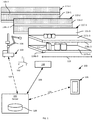
- FIG. 1 depicts a mobile automation system 100 in accordance with the teachings of this disclosure.
- the system 100 includes a server 101 in communication with at least one mobile automation apparatus 103 (also referred to herein simply as the apparatus 103 ) and at least one client computing device 105 via communication links 107 , illustrated in the present example as including wireless links.
- the links 107 are provided by a wireless local area network (WLAN) deployed within the retail environment by one or more access points (not shown).
- WLAN wireless local area network
- the server 101 , the client device 105 , or both, are located outside the retail environment, and the links 107 therefore include wide-area networks such as the Internet, mobile networks, and the like.
- the system 100 also includes a dock 108 for the apparatus 103 in the present example.
- the dock 108 is in communication with the server 101 via a link 109 that in the present example is a wired link. In other examples, however, the link 109 is a wireless link.
- a link 109 is a wired link.
- the link 109 is a wireless link.
- the client computing device 105 is illustrated in FIG. 1 as a mobile computing device, such as a tablet, smart phone or the like. In other examples, the client device 105 is implemented as another type of computing device, such as a desktop computer, a laptop computer, another server, a kiosk, a monitor, and the like.
- the system 100 can include a plurality of client devices 105 in communication with the server 101 via respective links 107 .
- the system 100 is deployed, in the illustrated example, in a retail environment including a plurality of support structures in the form of shelf modules 110 - 1 , 110 - 2 , 110 - 3 and so on (collectively referred to as shelf modules 110 , and generically referred to as a shelf module 110 —this nomenclature is also employed for other elements discussed herein).
- shelf modules 110 Various other support structures for supporting inventoried retail and/or warehouse items disposed thereon are contemplated, including shelves, racks (including racks for hanging inventoried objects, such as clothing racks), peg boards, and the like.
- Each shelf module 110 supports a plurality of products 112 .
- Each shelf module 110 includes a shelf back 116 - 1 , 116 - 2 , 116 - 3 and one or more support surfaces (e.g. an upper support surface 117 a - 3 and a lower support surface 117 b - 3 as illustrated in FIG. 1 ) extending from the shelf back 116 to a respective shelf edge (e.g. shelf edges 118 a - 1 , 118 a - 2 , 118 a - 3 and 118 b - 3 ).
- the shelf modules 110 are typically arranged in a plurality of aisles, each of which includes a plurality of modules 110 aligned end-to-end.
- the shelf edges 118 face into the aisles, through which customers in the retail environment as well as the apparatus 103 may travel.
- the shelf edges 118 typically bear labels, such as adhesive labels affixed to the shelf edges 118 , corresponding to the products 112 and therefore including information such as product names, barcodes or other machine-readable indicators, prices, and the like.
- shelf edge 118 as employed herein, which may also be referred to as the edge of a support surface of a support structure (e.g., the support surfaces 117 ) refers to a surface bounded by adjacent surfaces having different angles of inclination.
- the shelf edges 118 a - 3 is at an angle of about ninety degrees relative to each of the support surface 117 a - 3 and the underside (not shown) of the support surface 117 a - 3 .
- the angles between the shelf edges 118 and the adjacent surfaces, such as the support surfaces 117 is more or less than ninety degrees.
- the apparatus 103 is deployed within the retail environment, and communicates with the server 101 (e.g. via the link 107 ) to navigate, autonomously or partially autonomously, along a length 119 of at least a portion of the shelf modules 110 .
- the apparatus 103 is configured to navigate among the shelf modules 110 , for example according to a frame of reference 102 established within the retail environment.
- the frame of reference 102 can also be referred to as a global frame of reference.
- the apparatus 103 is configured, during such navigation, to track the location of the apparatus 103 relative to the frame of reference 102 .
- the apparatus 103 is configured to perform localization.
- the apparatus 103 is equipped with one or more navigation sensors, including but not limited to image sensors, depth sensors, as well as gyroscopes and/or accelerometers, enabling the apparatus 103 to navigate within the environment.
- the apparatus 103 also includes an effector assembly 104 bearing a label manipulator, to be discussed in greater detail below.
- the apparatus 103 is configured, for example responsive to commands received from the server 101 , to navigate among the shelf modules 110 and replace the above-mentioned labels affixed to the shelf edges 118 with the effector assembly 104 and associated components. For example, certain labels may require periodic replacement to reflect updated prices, reallocation of products 112 among the shelf modules 110 , and the like.
- the server 101 includes a memory storing a repository 120 containing label placement data, for example in the form of a planogram indicating the locations (e.g. in the frame of reference 102 ) of each shelf module 110 , as well as the location of each label on each shelf module.
- Label locations may be expressed in the repository 120 as a distance along a specified shelf edge 118 relative to a reference feature of the module 110 , such as a boundary of the module 110 (e.g. the left side of the module 110 ).
- the label placement data in the repository 120 can also contain further data defining each label, such as the label type (i.e. the physical format of the label), the product identifier corresponding to the label, and the like.
- the apparatus 103 includes a chassis 200 containing a locomotive mechanism 204 (e.g. one or more electrical motors driving wheels, tracks or the like).
- the chassis 200 supports additional components of the apparatus 103 , including a mast 208 which in turn supports the effector assembly 104 .
- the effector assembly 104 in the present example, is a robotic arm fixed to the chassis 200 (via the mast 208 ) at a first end 212 .
- a second end of the effector assembly 104 is movable relative to the chassis 200 , for example with six degrees of freedom (e.g.
- the second end of the effector assembly 104 carries a label manipulator 216 .
- the label manipulator 216 is configured to grasp labels and to release labels, as well as to capture data (e.g. image data) for use in positioning the manipulator 216 via control of the effector assembly 104 .
- the apparatus 103 also includes a receptacle 220 for receiving discarded labels removed from shelf edges 118 by the manipulator 216 .
- the apparatus 103 further includes a label generator 224 for generating new labels for placement on the shelf edges 118 via control of the effector assembly 104 and the manipulator 216 .
- the label generator 224 in the present example, is a label printer containing, for example, a roll of blank adhesive-backed labels and a printhead configured to apply pigmentation (e.g. ink, thermally-induced pigment changes in the blank labels, or the like) to blank labels.
- Embodiments of the printer 224 include a direct thermal printer and a thermal transfer printer.
- the printer 224 can be configured to remove the backing from printed labels as the labels exit the printer 224 .
- the label generator 224 can include a supply of previously printed (or otherwise previously generated) labels, and is configured to simply dispense the previously generated labels via an outlet.
- the apparatus 103 also includes a pressure generator 228 configured to supply one or both of a vacuum (i.e. negative pressure) or pressurized air to the manipulator 216 to allow the manipulator 216 to grasp and release labels.
- the generator 228 can be implemented as a plurality of distinct components, such as one or more pumps and associated storage tanks (e.g. air storage tanks).
- the memory 254 stores computer readable instructions for execution by the processor 250 .
- the memory 254 stores a control application 258 which, when executed by the processor 250 , configures the processor 250 to perform various functions discussed below in greater detail and related to the navigation of the apparatus 103 (e.g. by controlling the locomotive mechanism 203 ).
- the application 258 may also be implemented as a suite of distinct applications in other examples.
- the processor 250 when so configured by the execution of the application 258 , may also be referred to as a controller 250 .
- the functionality implemented by the processor 250 via the execution of the application 258 may also be implemented by one or more specially designed hardware and firmware components, such as FPGAs, ASICs and the like in other embodiments.
- the memory 254 also stores a repository 260 containing, for example, a map of the environment in which the apparatus 103 is deployed, for use in navigation among the shelf modules 110 .
- the apparatus 103 may communicate with the server 101 , for example to receive instructions to navigate to specified locations (e.g. to a given aisle consisting of a set of modules 110 ) and initiate label replacement operations. Navigation to the specified module 110 is implemented by the apparatus 103 based in part on the above-mentioned map.
- the repository 260 can also contain label placement data (e.g. received from the server 101 ) for use in replacing labels on the shelf modules 110 .
- the processor 250 is connected to the effector assembly 104 and the pressure generator 228 .
- the processor 250 is enabled, via such connections, to issue commands to the effector assembly 104 to control the position of the label manipulator 216 relative to the chassis 200 , and to enable the pressure generator 228 to generate positive or negative air pressure for application at the manipulator 216 .
- the apparatus 103 can also include a pressure sensor 266 , for example mounted within the manipulator 216 or within an air conduit running between the generator 228 and the manipulator 216 .
- the pressure sensor 266 is configured to provide pressure measurements to the processor 250
- the processor 250 is configured to detect, based at least in part on comparing the pressure measurements to a predetermined pressure threshold required to grasp the label, whether a label is currently grasped by the manipulator 216 .
- the apparatus 103 further includes an image sensor 270 connected with the processor 250 .
- the image sensor 270 which can be for example a digital color camera (e.g. configured to generate RGB images), a greyscale camera, an infrared camera or the like, is implemented as a component of the manipulator 216 , as will be discussed in greater detail below.
- the image sensor 270 is controllable by the processor 250 to capture images of the shelf modules 110 in order to locate the manipulator 216 and manipulate labels on the shelf edges 118 .
- the apparatus 103 also includes a communications interface 274 enabling the apparatus 103 to communicate with other computing devices, such as the server 101 over the link 107 shown in FIG. 1 .
- the communications interface 274 also enables the apparatus 103 to communicate with the server 101 via the dock 108 and the link 109 .
- FIGS. 3A and 3B the manipulator 216 is shown in greater detail.
- FIG. 3A illustrates a top view of the manipulator 216 , when the manipulator 216 is oriented to remove or place a label on a shelf edge 118 .
- FIG. 3B illustrates a front view of the manipulator 216 , the front being the portion of the manipulator 216 configured to contact the shelf edge 118 .
- the manipulator 216 includes a base wall 300 with a seal 304 extending along the perimeter of the base wall 300 .
- the seal 304 can be fabricated of a flexible material, such as rubber, silicone or the like, to deform upon contact with a shelf edge 118 .
- the base wall 300 is placed substantially parallel to the shelf edge 118 .
- the seal 304 is configured to engage the shelf edge 118 to create a substantially sealed cavity around a portion of the shelf edge 118 , defined by the seal 304 and the base wall 300 . In such an embodiment, as shown in FIG.
- a mesh may be disposed across the opening at the front of the seal 304 , to prevent labels from entering the cavity defined by the seal 304 , which prevents the labels from entering and/or otherwise obstructing the air conduit 308 and protects the sensors 266 , 270 .
- FIGS. 3A and 3B Also shown in FIGS. 3A and 3B is an air conduit 308 connecting the manipulator 216 with the pressure generator 228 .
- the air conduit 308 is shown as being disposed within the effector assembly 104 , but in other embodiments can be disposed on an exterior surface of the effector assembly 104 .
- the conduit 308 is configured to transmit pressurized air or vacuum from the generator 228 to the manipulator 216 , for use in retaining or expelling a label sealed abutting the front of the seal 304 .
- FIG. 4 illustrates a method 400 of labeling support structures, which will be described in conjunction with its performance in the system 100 , and in particular by the apparatus 103 , with reference to the components illustrated in FIGS. 2A, 2B, 3A and 3B .
- the apparatus 103 is configured to obtain label placement data.
- the label placement data can be obtained from the server 101 over the link 107 or via the dock 108 .
- the label placement data can be received from the client device 105 .
- the label placement data defines at least one location in the facility for performance of a label manipulation operation, such as replacement of a previous label at the location with a new label, placement of a label in a previously unlabeled location, or removal of a previous label, without replacement of the label.
- the locations are locations on the shelf edges 118 of the shelf modules 110 . Further, in the present example, the locations are defined relative to a reference feature on the support structure.
- each label replacement location is defined as an offset distance along a shelf edge 118 of a shelf module 110 .
- the offset distance is defined from a side of the module 110 (e.g. the leftmost side of the module 110 , also referred to as the boundary of the module 110 ).
- various other reference features can be employed to define the locations in the label placement data, such as machine-readable markers (e.g. physical features of the shelf, graphical indicators such as QR codes, or the like) along the shelf edges, ends of a shelf edge 118 within the boundaries of a module 110 (e.g. when a shelf edge 118 does not extend along the full length 119 of the module 110 ), and the like.
- the label placement data obtained at block 405 therefore contains, in the present example, an identifier of a shelf module 110 , an identifier of a shelf edge 118 of the identified module 110 , and an offset distance along the identified shelf edge 118 , from a predetermined reference feature of the identified module 110 .
- the label placement data can also include label generation data, such as an image for printing on label substrate, or a product identifier permitting the apparatus 103 to retrieve or generate such a label image.
- the label placement data obtained at block 405 can also include an indication of the previous label to be replaced (e.g. a product identifier or the like). Table 1, below, illustrates example label placement data obtained at block 405 .
- Label generation data includes an identification of a label format, which may specify both the size of the label as above, and the arrangement of information on the label (not shown above).
- the product identifiers are employed by the apparatus 103 to retrieve information with which to populate the label format for generation of the label.
- the apparatus 103 is configured to navigate to the next support structure (e.g. the next module 110 ) identified in the label placement data. Navigation is performed via suitable mechanism, such as via the use of the above-mentioned map, navigational sensors of the apparatus 103 , and the like. In the present example, the apparatus 103 is configured to navigate to a predetermined location relative to the module 110 .
- modules 110 may have lengths of about 1.5 m (other module lengths are also contemplated, for example from about 1 m to about 2 m), and the effector assembly 104 may have a reach of about 1 m.
- the apparatus 103 is configured to navigate to a position at a predefined depth relative to the module 110 , approximately half-way along the length 119 of the module 110 , from which the effector assembly 104 can reach any portion of the shelf edges 118 of the module 110 .
- FIG. 6A illustrates such a position, with the apparatus 103 having arrived at a depth 600 relative to the module 110 , about half-way along the length 119 of the module.
- the apparatus 103 is not exactly half-way along the length 119 .
- localization based on inertial sensing e.g. via accelerometers and gyroscopes
- localization based on odometry e.g. via a wheel encoder coupled to the locomotive mechanism 203
- the internal localization maintained by the apparatus 103 may therefore not align exactly with the true position of the apparatus 103 within the environment.
- the apparatus 103 is also configured to place the manipulator 216 at an initial location, from which detection of the above-mentioned reference feature will be initiated.
- Positioning of the manipulator 216 is achieved via control of the effector assembly 104 , for example by issuing commands from the processor 250 to the effector assembly 104 specifying coordinates (e.g. X, Y, Z coordinates and roll, pitch and yaw angles) that define a position and orientation of the manipulator 216 relative to the chassis 200 .
- the effector assembly 104 includes positional sensors (not shown) configured to track the position of the second end (i.e. the manipulator 216 ) of the effector assembly 104 relative to the first end 212 , enabling the effector assembly 104 to position the manipulator 216 responsive to the above-mentioned commands from the processor 250 .
- the initial location is selected based on the known position (in the frame of reference 102 ) of the shelf edge 118 identified in the label placement data, as well as on the predetermined position to which the apparatus 103 navigated at block 410 , and on a navigational error boundary.
- the navigational error mentioned above may have been previously characterized as reaching a maximum of about 0.1 m.
- the height of the apparatus 103 and of the first end 212 of the effector assembly 104 on the apparatus 103 are previously determined, as is the height of the shelf edge 118 a identified in the label placement data shown above.
- the reference feature is the boundary 516
- the apparatus 103 is therefore configured to control the effector assembly 104 to place the manipulator 216 at an initial location at the height of the shelf edge 118 a , at a horizontal position adjacent to the boundary 516 .
- the manipulator 216 may be placed at a distance parallel to the length 119 of about 0.85 m (half of the length 119 plus the maximum potential navigational error of 0.1 m).
- the apparatus 103 is configured to control the image sensor 270 to capture an image. As shown in FIG. 6A , the manipulator 216 is positioned to orient the image sensor 270 towards the module 110 . The image captured at block 415 therefore depicts a portion of the shelf edge 118 a identified in the label placement data.
- the apparatus 103 is configured to determine whether the reference feature is detected in the image captured at block 415 . When the determination is negative, the apparatus 103 is configured to repeat the performance of blocks 415 and 420 , incrementing the location of the manipulator 216 along the shelf edge 118 a for each image capture.
- each incremental movement of the manipulator 216 at block 415 maintains the manipulator 216 at a predetermined height (e.g. the height of the shelf edge 118 a as specified in the repository 120 , the repository 260 , or the label placement data itself) and changes the horizontal location by a predetermined increment to shift the field of view of the image sensor 270 .
- a predetermined height e.g. the height of the shelf edge 118 a as specified in the repository 120 , the repository 260 , or the label placement data itself
- FIG. 6B movement of the effector assembly 104 is illustrated, causing the manipulator 216 to traverse a portion of the shelf edge 118 from an initial position 604 (shown in FIG. 6A ) to a further position 608 .
- FIG. 6C shows a sequence of three images 612 , 616 and 620 captured during the traverse shown in FIG. 6B .
- the determination at block 420 includes determining whether the image captured at block 415 contains a substantially vertical gradient change (e.g. from light, to dark, and back to light) indicative of a gap between modules 110 (which indicates the presence of the module boundary 516 ).
- the determination includes the application of a suitable gradient detection operation, edge detection operation or the like.
- a substantially vertical gradient change e.g. from light, to dark, and back to light
- the image 612 depicts a shelf edge of an adjacent module 110 , and does not contain the boundary 516 .
- the image 616 contains a partial representation of the gap between modules 110 , but does not contain the boundary 516 (e.g. does not contain the complete dark-light-dark transition mentioned above).
- the image 620 meanwhile, contains a dark-light-dark transition representing the boundary 516 . Responsive to capturing the image 620 , therefore, the determination at block 420 is affirmative and the performance of the method 400 proceeds to block 425 .
- the position of the image sensor 270 is fixed relative to the position of the manipulator 216 .
- the image sensor 270 is disposed at the center of the manipulator 216 , and thus the position of the image sensor 270 and of the manipulator 216 relative to a shelf edge 118 are equivalent.
- the image sensor 270 need not be centered on the base wall 300 , but the position of the image sensor 270 relative to the center of the base wall 300 is nevertheless predetermined. Therefore, the location of a reference feature in an image captured by the image sensor 270 indicates the position of the image sensor itself (and therefore the position of the manipulator 216 ) relative to the reference feature.
- the apparatus 103 is configured to control the effector assembly 104 to place the manipulator 216 at the next location defined in the label placement data.
- the apparatus 103 is configured to move the effector assembly 104 to place the manipulator 216 at the specified offset relative to the reference feature.
- the effector assembly 104 is controlled to place the manipulator 150 mm to the right (in the orientation shown in FIGS. 5, 6A and 6B ) of the boundary 516 .
- the apparatus 103 is configured to replace a label at the location specified in the label placement data. The replacement of a label at block 430 will be discussed in greater detail in connection with FIG. 7 .
- the apparatus 103 is configured to determine whether further labels remain to be placed on the current support structure (that is, the current module 110 , to which the apparatus 103 navigated at block 410 ). The determination at block 435 is made with reference to the label placement data obtained at block 405 . If all listed labels in the label placement data for the current module 110 have been placed, the determination at block 435 is negative. When the determination at block 435 is negative, the apparatus 103 proceeds to block 440 . Otherwise, the apparatus 103 returns to block 425 to place the next label for the current support structure.
- the apparatus 103 is configured to determine whether support structures other than the current support structure are identified in the label placement data and remain to be processed. In the example data shown in Table 1 above, only one module 110 is identified. In other examples, however, the label placement data can identify label placement locations on a plurality of distinct modules 110 . When the determination at block 440 is affirmative, the apparatus 103 returns to block 410 to navigate to the next module 110 in the label placement data. As will now be apparent, during the performance of blocks 415 to 435 , the apparatus 103 is configured to remain stationary relative to the current module 110 . That is, although the effector assembly 104 and manipulator 216 move, the chassis 200 remains stationary relative to the module 110 , thus mitigating or eliminating the accumulation of further navigational errors during the label placement process.
- FIG. 7 illustrates a method 700 of label replacement which will be described in conjunction with its performance in the system 100 , and in particular by the apparatus 103 , with reference to the components illustrated in FIGS. 2A, 2B and 3 .
- the apparatus 103 is configured to detect a previous label at the label placement location. Detection of a previous label is achieved, in the present example, by controlling the image sensor 270 to capture one or more images of the shelf edge 118 from the current location of the manipulator 216 (i.e. the location specified in the label placement data for placement of a label).
- the processor 250 is configured to process the captured image(s) to detect a label therein. Label detection can be performed via the detection of a barcode or other label features such as strings of text in a captured image, the detection of one or more edge features (e.g. indicated by gradient changes or the like), or a combination of the above.
- the processor 250 is configured to increment the location of the manipulator 216 to center the manipulator 216 over the partially detected label, and to then capture a further image via the image sensor 270 and repeat the detection.
- FIG. 8B an example image 800 captured via the image sensor 270 is shown.
- the image 800 depicts a portion of the shelf edge 118 a , and depicts a portion of a previous label 804 affixed to the shelf edge 118 a .
- the partial detection of the previous label 804 may indicate that the previous label 804 was not placed exactly at the specified location.
- the processor 250 can be configured to control the effector assembly 104 to move the manipulator 216 along the shelf edge 118 a in the direction of the partially detected label 804 and to capture a further image.
- a further image 808 is shown in FIG. 8C , in which the previous label 804 is fully visible.
- the processor 250 detects the previous label 804 as being coincident with the current position of the manipulator 216 and therefore suitable for removal.
- the processor 250 can also be configured to compare the detected label (e.g. a product identifier decoded from a barcode) to previous label data included in the label placement data. When the previous label detected at block 705 does not match the expected previous label, the processor 250 can be configured to store an error message in the memory 254 .
- the processor 250 can also be configured to select a removal mechanism for the previous label 804 .
- the apparatus 103 is equipped with a single removal mechanism (heated air, delivered via the generator 228 and the heater 262 ). In other examples, however, as noted above, additional removal mechanisms may be deployed on the apparatus 103 (e.g. ultraviolet light).
- the selection at block 705 can be based on the label 804 itself.
- the label placement data or other data in the repository 260 can contain indications of suitable removal mechanisms for each label format, or for particular product identifiers. In other examples, such data is maintained in the repository 120 , and the apparatus 103 transmits a request (e.g. containing the image 808 itself, a product identifier decoded from the barcode on the label 804 , or the like) for a removal mechanism to the server 101 .
- the apparatus 103 is configured, at block 710 , to extend the manipulator 216 towards the shelf edge 118 and to apply the selected removal mechanism. Extension of the manipulator 216 is performed to bring the seal 304 into contact with one or both of the shelf edge 118 a and the previous label 804 .
- the processor 250 is configured to control the effector assembly 104 to extend the manipulator 216 towards the shelf edge 118 a until, for example, one or more sensors (e.g. strain gauges or the like) in the effector assembly 104 register a threshold resistance indicating that the seal 304 has contacted the shelf edge 118 a .
- FIG. 9A the manipulator 216 is shown following extension to contact the shelf edge 118 a . As shown in FIG. 9A , the seal 304 has deformed against the shelf edge 118 a to form the previously mentioned cavity, indicated at 900 .
- the processor 250 is configured to apply the selected removal mechanism.
- the processor 250 is configured to control the generator 228 to emit pressurized air into the conduit 308 for emission into the cavity 900 , and to enable the heater 262 to heat the above-mentioned pressurized air. Heated air can be applied to the cavity (and therefore to the previous label 804 within the cavity 900 ) for a predetermined period of time, or until a thermal sensor (not shown) in the manipulator 216 indicates that the previous label 804 has reached a predetermined temperature (e.g. beyond which an adhesive affixing the label 804 to the shelf edge 118 a is expected to soften).
- a predetermined temperature is a temperature of about 60 degrees Celsius (140 degrees Fahrenheit)
- the processor 250 is configured to interrupt application of the removal mechanism and to apply a vacuum to the cavity 900 before retracting the manipulator 216 from the shelf edge 118 a .
- the processor 250 is configured to disable the heater 262 and to control the generator 228 to apply a vacuum to the cavity 900 via the conduit 308 .
- the vacuum applied to the cavity 900 serves to secure the previous label 804 to the seal 304 .
- Retraction of the manipulator 216 then serves to remove the previous label 804 from the shelf edge, the adhesive securing the previous label 804 having been softened by the application of heat at block 710 .
- the processor 250 is configured to determine whether a vacuum is maintained within the cavity 900 after retraction of the manipulator 216 (e.g. to a depth from the module 110 as shown in FIG. 6B ). The determination at block 720 is made by receiving sensor data from the pressure sensor 266 and comparing the sensor data to a threshold to determine whether the cavity 900 remains under negative pressure (i.e. remains closed at the seal 304 by the label 804 ), or whether the cavity 900 is open, indicating that the label 804 has not been removed from the shelf edge 118 a . When the determination at block 720 is negative, the apparatus 103 is configured to repeat the performance of block 710 . When the determination at block 720 is affirmative, the processor 250 is configured to proceed to block 725 .
- the processor 250 is configured to control the effector assembly 104 to place the manipulator 216 adjacent to the receptacle 220 .
- the receptacle 220 is affixed to the chassis 200 , and therefore has a predetermined position relative to the first end 212 of the effector assembly 104 .
- the processor 250 is therefore configured to issue a command to the effector assembly 104 to place the manipulator 216 at the above-mentioned predetermined position, and to remove the vacuum from the manipulator 216 . Removal of the vacuum, as will now be apparent, permits the previous label 804 to fall into the receptacle 220 . In some examples, the removal of the vacuum can be supplemented with application of pressurized air into the manipulator 216 to expel the label 804 .
- the processor 250 is configured to control the effector assembly 104 to place the manipulator 216 at an outlet of the label generator 224 .
- a location of the label generator 224 relative to the first end 212 of the effector assembly 104 can be stored in the memory 254 and transmitted to the effector assembly 104 at block 730 .
- the label generator 224 is a label printer in the present example, and is configured to generate a label according to the label placement data responsive to an instruction from the processor 250 .
- the processor 250 is further configured to apply a vacuum to the manipulator 216 at block 730 , for example responsive to a signal from the label generator 224 indicating that generation of the new label is complete. In other examples, the vacuum is applied responsive to detection of the new label at the outlet of the label generator 224 in an image captured by the image sensor 270 .
- the performance of the method 700 can skip from block 705 directly to block 730 .
- the processor 250 Responsive to obtaining the new label from the label generator 224 at block 730 (which can be confirmed via a vacuum assessment as described in conjunction with block 720 ), at block 735 the processor 250 is configured to reposition the manipulator 216 to the label placement location defined in the label placement data (i.e. the initial location referred to in connection with block 705 and shown in FIG. 8A ). The processor 250 is then configured to extend the manipulator 216 towards the shelf edge 118 a as shown in FIG. 9A , and to apply pressurized air to the manipulator 216 via control of the generator 228 .
- the extension of the manipulator 216 to contact the shelf edge 118 a presses the new label against the shelf edge 118 a to affix the new label to the shelf edge 118 a (via adhesive on the back of the new label).
- the processor 250 is configured to determine whether the new label was successfully placed at block 735 .
- the processor 250 can be configured to retract the manipulator 216 from the shelf edge 118 a and control the image sensor 270 to capture an image of the shelf edge 118 a .
- the determination at block 740 is affirmative, and the apparatus returns to block 435 of the method 400 .
- FIG. 9B illustrates an image 904 captured at block 740 , and showing that a new label 908 has been successfully affixed to the shelf edge 118 a.
- the new label is assumed to have fallen from the manipulator 216 or the shelf edge 118 a , and the apparatus 103 returns to block 730 to obtain another copy of the new label from the label generator 224 .
- the effector assembly 104 carries a plurality of manipulators 216 .
- FIG. 10 a front view of a manipulator set 1000 is shown, including manipulators 1004 - 1 , 1004 - 2 , 1004 - 3 , 1004 - 4 supported by a central manipulator housing 1008 disposed on the second end of the effector assembly.
- the housing 1008 is rotatable relative to the effector assembly (e.g. via a suitable motor included within the effector assembly 104 and controllable by the processor 250 ), to place any one of the manipulators 1004 against a shelf edge 118 a .
- the above-mentioned conduit 308 travels to the housing 1008 , and individual conduits 1012 connect the conduit 308 to each manipulator 1004 .
- the conduits 1012 are individually controllable, e.g. via a set of valves in the housing 1008 .
- the apparatus 103 can be configured to repeat blocks 705 - 720 for a plurality of label locations (one location per manipulator 1004 ) to remove a plurality of labels.
- the plurality of previous labels can then be discarded at block 725 , and a plurality of new labels can be collected at block 730 (e.g. by rotating the housing 1008 to successively place each manipulator 1004 at the outlet of the label generator 224 ).
- the apparatus 103 is then configured to repeat the performance of blocks 735 and 740 for each collected label.
- the travel of the manipulator 216 from the shelf edge 118 a to the receptacle 220 , to the label generator 224 , and back to the shelf edge 118 a need only be performed once for each set of labels equal in number to the number of manipulators 1004 in the set 1000 .
- the manipulator 216 can include a mechanical removal mechanism suitable for direct contact with a label, such as a scraper.
- the performance of block 410 of the method 400 includes only placement of the manipulator 216 at an initial location, without navigating to a support structure.
- the apparatus 103 may lack a controllable locomotive mechanism, and may instead be moved to the support structure by an operator. Following arrival at the support structure, the operator may activate an input on the apparatus 103 to initiate the performance of block 410 (that is, the control of the manipulator 216 ).
- a includes . . . a”, “contains . . . a” does not, without more constraints, preclude the existence of additional identical elements in the process, method, article, or apparatus that comprises, has, includes, contains the element.
- the terms “a” and “an” are defined as one or more unless explicitly stated otherwise herein.
- the terms “substantially”, “essentially”, “approximately”, “about” or any other version thereof, are defined as being close to as understood by one of ordinary skill in the art, and in one non-limiting embodiment the term is defined to be within 10%, in another embodiment within 5%, in another embodiment within 1% and in another embodiment within 0.5%.
- the term “coupled” as used herein is defined as connected, although not necessarily directly and not necessarily mechanically.
- a device or structure that is “configured” in a certain way is configured in at least that way, but may also be configured in ways that are not listed.
- processors such as microprocessors, digital signal processors, customized processors and field programmable gate arrays (FPGAs) and unique stored program instructions (including both software and firmware) that control the one or more processors to implement, in conjunction with certain non-processor circuits, some, most, or all of the functions of the method and/or apparatus described herein.
- processors or “processing devices” such as microprocessors, digital signal processors, customized processors and field programmable gate arrays (FPGAs) and unique stored program instructions (including both software and firmware) that control the one or more processors to implement, in conjunction with certain non-processor circuits, some, most, or all of the functions of the method and/or apparatus described herein.
- FPGAs field programmable gate arrays
- unique stored program instructions including both software and firmware
Landscapes
- Image Analysis (AREA)
- Manipulator (AREA)
- Labeling Devices (AREA)
Abstract
Description
| TABLE 1 |
| Example Label Placement Data |
| Module | Shelf edge | Offset (mm) | Label | Product ID | |
| 110 | 118a | 150 | 1″ × 3″ | 765554 | |
| 110 | 118a | 165 | 1″ × 3″ | 778633 | |
| . . . | . . . | . . . | . . . | ||
Claims (21)
Priority Applications (6)
| Application Number | Priority Date | Filing Date | Title |
|---|---|---|---|
| US16/047,220 US10934045B2 (en) | 2018-07-27 | 2018-07-27 | Method and apparatus for labeling of support structures |
| CN201980050121.8A CN112533837B (en) | 2018-07-27 | 2019-05-30 | Method and apparatus for marking of support structures |
| PCT/US2019/034561 WO2020023110A1 (en) | 2018-07-27 | 2019-05-30 | Method and apparatus for labeling of support structures |
| DE112019003798.6T DE112019003798T5 (en) | 2018-07-27 | 2019-05-30 | METHOD AND DEVICE FOR LABELING SUPPORT STRUCTURES |
| AU2019310299A AU2019310299B2 (en) | 2018-07-27 | 2019-05-30 | Method and apparatus for labeling of support structures |
| GB2100838.8A GB2596375B (en) | 2018-07-27 | 2019-05-30 | Method and apparatus for labeling of support structures |
Applications Claiming Priority (1)
| Application Number | Priority Date | Filing Date | Title |
|---|---|---|---|
| US16/047,220 US10934045B2 (en) | 2018-07-27 | 2018-07-27 | Method and apparatus for labeling of support structures |
Publications (2)
| Publication Number | Publication Date |
|---|---|
| US20200031513A1 US20200031513A1 (en) | 2020-01-30 |
| US10934045B2 true US10934045B2 (en) | 2021-03-02 |
Family
ID=69177841
Family Applications (1)
| Application Number | Title | Priority Date | Filing Date |
|---|---|---|---|
| US16/047,220 Active 2038-11-26 US10934045B2 (en) | 2018-07-27 | 2018-07-27 | Method and apparatus for labeling of support structures |
Country Status (6)
| Country | Link |
|---|---|
| US (1) | US10934045B2 (en) |
| CN (1) | CN112533837B (en) |
| AU (1) | AU2019310299B2 (en) |
| DE (1) | DE112019003798T5 (en) |
| GB (1) | GB2596375B (en) |
| WO (1) | WO2020023110A1 (en) |
Families Citing this family (4)
| Publication number | Priority date | Publication date | Assignee | Title |
|---|---|---|---|---|
| US11090811B2 (en) * | 2018-11-13 | 2021-08-17 | Zebra Technologies Corporation | Method and apparatus for labeling of support structures |
| US11673703B1 (en) * | 2019-06-07 | 2023-06-13 | Wm Recycle America, L.L.C. | Apparatus and method for applying labels to a customer container from a waste collection, disposal and/or recycling vehicle |
| US12252293B2 (en) * | 2021-03-22 | 2025-03-18 | Zebra Technologies Corporation | Adhesive label application system for a robotic device |
| CN116872487A (en) * | 2023-06-05 | 2023-10-13 | 东莞市雅创自动化科技有限公司 | Appearance detection film-pasting and disc-arranging integrated machine and control method thereof |
Citations (26)
| Publication number | Priority date | Publication date | Assignee | Title |
|---|---|---|---|---|
| US5423617A (en) | 1993-04-27 | 1995-06-13 | Csir | Shelf mountable printing apparatus |
| WO1997025204A1 (en) | 1996-01-04 | 1997-07-17 | Aman James A | Automated end labeler system |
| US5674335A (en) * | 1995-01-06 | 1997-10-07 | Aman; James A. | Automated end labeler system |
| US5704049A (en) | 1992-12-22 | 1997-12-30 | Electronic Retailing Systems International Inc. | Subglobal area addressing for electronic price displays |
| US20060279527A1 (en) | 1999-05-03 | 2006-12-14 | E Ink Corporation | Machine-readable displays |
| US20090314413A1 (en) | 2007-12-07 | 2009-12-24 | R.E.D. Stamp, Inc. | Apparatus and method for applying tax stamps |
| US20120197439A1 (en) | 2011-01-28 | 2012-08-02 | Intouch Health | Interfacing with a mobile telepresence robot |
| US20130076586A1 (en) | 2010-06-01 | 2013-03-28 | Marisense Oy | Arrangement for reducing interference in an electronic shelf label |
| US20150363625A1 (en) | 2014-06-13 | 2015-12-17 | Xerox Corporation | Image processing methods and systems for barcode and/or product label recognition |
| CN105857813A (en) | 2016-03-31 | 2016-08-17 | 河北科技大学 | Automatic vision-based labeling device for end faces of reinforcing steel bars in bundle |
| US20170032311A1 (en) | 2014-06-13 | 2017-02-02 | Xerox Corporation | Store shelf imaging system and method |
| US20170286773A1 (en) | 2016-03-29 | 2017-10-05 | Bossa Nova Robotics Ip, Inc. | Planogram Assisted Inventory System and Method |
| WO2017187106A1 (en) | 2016-04-29 | 2017-11-02 | Antoine Rennuit | Method for treating a surface and corresponding automated device |
| US20170323253A1 (en) | 2016-05-04 | 2017-11-09 | Wal-Mart Stores, Inc. | Distributed Autonomous Robot Systems and Methods |
| US20180001481A1 (en) | 2016-05-19 | 2018-01-04 | Simbe Robotics, Inc. | Method for automatically generating waypoints for imaging shelves within a store |
| CN206952978U (en) | 2017-05-23 | 2018-02-02 | 上海全筑建筑装饰集团股份有限公司 | A kind of setting-out robot for construction and decoration |
| US20180088586A1 (en) | 2016-09-26 | 2018-03-29 | X Development Llc | Identification Information for Warehouse Navigation |
| US20180101813A1 (en) | 2016-10-12 | 2018-04-12 | Bossa Nova Robotics Ip, Inc. | Method and System for Product Data Review |
| US20180108120A1 (en) | 2016-10-17 | 2018-04-19 | Conduent Business Services, Llc | Store shelf imaging system and method |
| US20180130011A1 (en) | 2015-02-19 | 2018-05-10 | Mycronic AB | Method, system and device for providing information on a display arranged on a carrier in a surface mount technology system |
| US20180190160A1 (en) | 2016-12-30 | 2018-07-05 | Wal-Mart Stores, Inc. | Electronic Shelf Label System |
| US20180293543A1 (en) | 2017-04-07 | 2018-10-11 | Simbe Robotics, Inc. | Method for tracking stock level within a store |
| US20190077015A1 (en) | 2017-09-12 | 2019-03-14 | Fanuc Corporation | Machine learning device, robot system, and machine learning method |
| US20190389078A1 (en) | 2018-06-22 | 2019-12-26 | Southwest Research Institute | Robotic System for Surface Treatment of Vehicles |
| US20200147803A1 (en) | 2018-11-13 | 2020-05-14 | Zebra Technologies Corporation | Method and apparatus for labeling of support structures |
| US20200147802A1 (en) | 2018-11-13 | 2020-05-14 | Zebra Technologies Corporation | Method and apparatus for labeling of support structures |
Family Cites Families (3)
| Publication number | Priority date | Publication date | Assignee | Title |
|---|---|---|---|---|
| CN1083330C (en) * | 1996-01-04 | 2002-04-24 | 詹姆斯·A·阿曼 | Automatic material end labeling machine and corresponding method |
| CN107284780B (en) * | 2017-06-27 | 2023-09-05 | 苏州有泰精密自动化有限公司 | Automatic labeling machine and labeling method |
| CN108146950A (en) * | 2017-12-14 | 2018-06-12 | 刘静 | It is a kind of can automatically move, the unmanned warehouse logistics robot of heap goods and joint strip code |
-
2018
- 2018-07-27 US US16/047,220 patent/US10934045B2/en active Active
-
2019
- 2019-05-30 GB GB2100838.8A patent/GB2596375B/en active Active
- 2019-05-30 CN CN201980050121.8A patent/CN112533837B/en active Active
- 2019-05-30 WO PCT/US2019/034561 patent/WO2020023110A1/en not_active Ceased
- 2019-05-30 DE DE112019003798.6T patent/DE112019003798T5/en not_active Withdrawn
- 2019-05-30 AU AU2019310299A patent/AU2019310299B2/en active Active
Patent Citations (26)
| Publication number | Priority date | Publication date | Assignee | Title |
|---|---|---|---|---|
| US5704049A (en) | 1992-12-22 | 1997-12-30 | Electronic Retailing Systems International Inc. | Subglobal area addressing for electronic price displays |
| US5423617A (en) | 1993-04-27 | 1995-06-13 | Csir | Shelf mountable printing apparatus |
| US5674335A (en) * | 1995-01-06 | 1997-10-07 | Aman; James A. | Automated end labeler system |
| WO1997025204A1 (en) | 1996-01-04 | 1997-07-17 | Aman James A | Automated end labeler system |
| US20060279527A1 (en) | 1999-05-03 | 2006-12-14 | E Ink Corporation | Machine-readable displays |
| US20090314413A1 (en) | 2007-12-07 | 2009-12-24 | R.E.D. Stamp, Inc. | Apparatus and method for applying tax stamps |
| US20130076586A1 (en) | 2010-06-01 | 2013-03-28 | Marisense Oy | Arrangement for reducing interference in an electronic shelf label |
| US20120197439A1 (en) | 2011-01-28 | 2012-08-02 | Intouch Health | Interfacing with a mobile telepresence robot |
| US20150363625A1 (en) | 2014-06-13 | 2015-12-17 | Xerox Corporation | Image processing methods and systems for barcode and/or product label recognition |
| US20170032311A1 (en) | 2014-06-13 | 2017-02-02 | Xerox Corporation | Store shelf imaging system and method |
| US20180130011A1 (en) | 2015-02-19 | 2018-05-10 | Mycronic AB | Method, system and device for providing information on a display arranged on a carrier in a surface mount technology system |
| US20170286773A1 (en) | 2016-03-29 | 2017-10-05 | Bossa Nova Robotics Ip, Inc. | Planogram Assisted Inventory System and Method |
| CN105857813A (en) | 2016-03-31 | 2016-08-17 | 河北科技大学 | Automatic vision-based labeling device for end faces of reinforcing steel bars in bundle |
| WO2017187106A1 (en) | 2016-04-29 | 2017-11-02 | Antoine Rennuit | Method for treating a surface and corresponding automated device |
| US20170323253A1 (en) | 2016-05-04 | 2017-11-09 | Wal-Mart Stores, Inc. | Distributed Autonomous Robot Systems and Methods |
| US20180001481A1 (en) | 2016-05-19 | 2018-01-04 | Simbe Robotics, Inc. | Method for automatically generating waypoints for imaging shelves within a store |
| US20180088586A1 (en) | 2016-09-26 | 2018-03-29 | X Development Llc | Identification Information for Warehouse Navigation |
| US20180101813A1 (en) | 2016-10-12 | 2018-04-12 | Bossa Nova Robotics Ip, Inc. | Method and System for Product Data Review |
| US20180108120A1 (en) | 2016-10-17 | 2018-04-19 | Conduent Business Services, Llc | Store shelf imaging system and method |
| US20180190160A1 (en) | 2016-12-30 | 2018-07-05 | Wal-Mart Stores, Inc. | Electronic Shelf Label System |
| US20180293543A1 (en) | 2017-04-07 | 2018-10-11 | Simbe Robotics, Inc. | Method for tracking stock level within a store |
| CN206952978U (en) | 2017-05-23 | 2018-02-02 | 上海全筑建筑装饰集团股份有限公司 | A kind of setting-out robot for construction and decoration |
| US20190077015A1 (en) | 2017-09-12 | 2019-03-14 | Fanuc Corporation | Machine learning device, robot system, and machine learning method |
| US20190389078A1 (en) | 2018-06-22 | 2019-12-26 | Southwest Research Institute | Robotic System for Surface Treatment of Vehicles |
| US20200147803A1 (en) | 2018-11-13 | 2020-05-14 | Zebra Technologies Corporation | Method and apparatus for labeling of support structures |
| US20200147802A1 (en) | 2018-11-13 | 2020-05-14 | Zebra Technologies Corporation | Method and apparatus for labeling of support structures |
Non-Patent Citations (4)
| Title |
|---|
| International Search Report and Written Opinion for International Application No. PCT/US2019/034561 dated Aug. 9, 2019. |
| International Search Report and Written Opinion for International Patent Application No. PCT/US2019/051312 dated Nov. 15, 2019. |
| International Search Report and Written Opinion for International Patent Application No. PCT/US2019/054103 dated Jun. 1, 2020. |
| Meyersohn. Walmart turns to robots and apps in stores, Dec. 7, 2018, retrieved from the Internet at [URL: https://www.cnn.com/2018/12/07/business/walmart-robot-janitors-dotcom-store/index.html] dated Oct. 29, 2019. |
Also Published As
| Publication number | Publication date |
|---|---|
| AU2019310299A1 (en) | 2021-01-28 |
| CN112533837A (en) | 2021-03-19 |
| GB2596375B (en) | 2022-09-28 |
| AU2019310299B2 (en) | 2021-02-04 |
| CN112533837B (en) | 2021-10-15 |
| DE112019003798T5 (en) | 2021-04-15 |
| US20200031513A1 (en) | 2020-01-30 |
| GB2596375A (en) | 2021-12-29 |
| GB202100838D0 (en) | 2021-03-10 |
| WO2020023110A1 (en) | 2020-01-30 |
Similar Documents
| Publication | Publication Date | Title |
|---|---|---|
| AU2019310299B2 (en) | Method and apparatus for labeling of support structures | |
| CN113016021B (en) | Method and apparatus for marking of support structures | |
| US11117263B2 (en) | Method and apparatus for labeling of support structures | |
| US11100303B2 (en) | Method, system and apparatus for auxiliary label detection and association | |
| US20180314908A1 (en) | Method and apparatus for label detection | |
| US20190311489A1 (en) | Method, system and apparatus for recovering label positions | |
| US20170270579A1 (en) | Robotic equipment for the location of items in a shop and operating process thereof | |
| CN107406162B (en) | Apparatus and corresponding method for managing commercial objects | |
| US20180203650A1 (en) | Label printer applicator system | |
| CN110497443A (en) | Grasping device, the container of tape label, object hold program and object holding method | |
| US20210262806A1 (en) | Method, System and Apparatus for Navigational Assistance | |
| CN213934902U (en) | Assembly line system for automatically reading electronic tags of products | |
| CN112744421A (en) | Label pasting system and pasting method | |
| US20220180559A1 (en) | On-Site Calibration for Mobile Automation Apparatus | |
| CN106446746A (en) | An RFID-based object-finding navigation system in space | |
| CN104401677A (en) | Physical distribution management system and physical distribution management method | |
| JP6629520B2 (en) | Robot system | |
| CN206236102U (en) | A kind of space based on RFID is looked for something navigation system | |
| US20200182623A1 (en) | Method, system and apparatus for dynamic target feature mapping | |
| US12252293B2 (en) | Adhesive label application system for a robotic device | |
| CN210270904U (en) | Device for automatically converting one-dimensional or two-dimensional code into electronic tag | |
| CN117621043A (en) | Method and autonomous robot for inventory taking in structures | |
| JP2008094541A (en) | Sorting cart and sorting system | |
| JP2023086277A (en) | Labeling device and method | |
| TW201947475A (en) | System for using automatic vehicle to confirm item positions and method thereof |
Legal Events
| Date | Code | Title | Description |
|---|---|---|---|
| FEPP | Fee payment procedure |
Free format text: ENTITY STATUS SET TO UNDISCOUNTED (ORIGINAL EVENT CODE: BIG.); ENTITY STATUS OF PATENT OWNER: LARGE ENTITY |
|
| AS | Assignment |
Owner name: ZIH CORP., ILLINOIS Free format text: ASSIGNMENT OF ASSIGNORS INTEREST;ASSIGNOR:BEACH, ROBERT E.;REEL/FRAME:046835/0636 Effective date: 20180904 |
|
| STPP | Information on status: patent application and granting procedure in general |
Free format text: DOCKETED NEW CASE - READY FOR EXAMINATION |
|
| AS | Assignment |
Owner name: ZEBRA TECHNOLOGIES CORPORATION, ILLINOIS Free format text: MERGER;ASSIGNOR:ZIH CORP.;REEL/FRAME:048470/0848 Effective date: 20181220 |
|
| AS | Assignment |
Owner name: JPMORGAN CHASE BANK, N.A., AS COLLATERAL AGENT, NEW YORK Free format text: SECURITY INTEREST;ASSIGNOR:ZEBRA TECHNOLOGIES CORPORATION;REEL/FRAME:049674/0916 Effective date: 20190701 |
|
| STPP | Information on status: patent application and granting procedure in general |
Free format text: RESPONSE TO NON-FINAL OFFICE ACTION ENTERED AND FORWARDED TO EXAMINER |
|
| AS | Assignment |
Owner name: JPMORGAN CHASE BANK, N.A., NEW YORK Free format text: SECURITY INTEREST;ASSIGNORS:ZEBRA TECHNOLOGIES CORPORATION;LASER BAND, LLC;TEMPTIME CORPORATION;REEL/FRAME:053841/0212 Effective date: 20200901 |
|
| STPP | Information on status: patent application and granting procedure in general |
Free format text: NOTICE OF ALLOWANCE MAILED -- APPLICATION RECEIVED IN OFFICE OF PUBLICATIONS |
|
| STCF | Information on status: patent grant |
Free format text: PATENTED CASE |
|
| AS | Assignment |
Owner name: ZEBRA TECHNOLOGIES CORPORATION, ILLINOIS Free format text: RELEASE OF SECURITY INTEREST - 364 - DAY;ASSIGNOR:JPMORGAN CHASE BANK, N.A.;REEL/FRAME:056036/0590 Effective date: 20210225 Owner name: TEMPTIME CORPORATION, NEW JERSEY Free format text: RELEASE OF SECURITY INTEREST - 364 - DAY;ASSIGNOR:JPMORGAN CHASE BANK, N.A.;REEL/FRAME:056036/0590 Effective date: 20210225 Owner name: LASER BAND, LLC, ILLINOIS Free format text: RELEASE OF SECURITY INTEREST - 364 - DAY;ASSIGNOR:JPMORGAN CHASE BANK, N.A.;REEL/FRAME:056036/0590 Effective date: 20210225 |
|
| MAFP | Maintenance fee payment |
Free format text: PAYMENT OF MAINTENANCE FEE, 4TH YEAR, LARGE ENTITY (ORIGINAL EVENT CODE: M1551); ENTITY STATUS OF PATENT OWNER: LARGE ENTITY Year of fee payment: 4 |