US10924716B2 - Image projection device - Google Patents
Image projection device Download PDFInfo
- Publication number
- US10924716B2 US10924716B2 US16/340,124 US201716340124A US10924716B2 US 10924716 B2 US10924716 B2 US 10924716B2 US 201716340124 A US201716340124 A US 201716340124A US 10924716 B2 US10924716 B2 US 10924716B2
- Authority
- US
- United States
- Prior art keywords
- light beam
- image
- region
- image light
- mirror
- Prior art date
- Legal status (The legal status is an assumption and is not a legal conclusion. Google has not performed a legal analysis and makes no representation as to the accuracy of the status listed.)
- Active
Links
- 210000001525 retina Anatomy 0.000 claims abstract description 58
- 230000003287 optical effect Effects 0.000 claims abstract description 43
- 230000000903 blocking effect Effects 0.000 claims abstract description 36
- 210000005252 bulbus oculi Anatomy 0.000 claims description 28
- 230000007935 neutral effect Effects 0.000 claims description 24
- 239000011295 pitch Substances 0.000 claims description 21
- 230000001678 irradiating effect Effects 0.000 abstract 1
- 210000000695 crystalline len Anatomy 0.000 description 47
- 210000001747 pupil Anatomy 0.000 description 13
- 230000000052 comparative effect Effects 0.000 description 6
- 230000000694 effects Effects 0.000 description 5
- 210000001508 eye Anatomy 0.000 description 5
- 238000010586 diagram Methods 0.000 description 2
- 238000000034 method Methods 0.000 description 2
- 206010047571 Visual impairment Diseases 0.000 description 1
- 238000010521 absorption reaction Methods 0.000 description 1
- 230000004075 alteration Effects 0.000 description 1
- 230000003190 augmentative effect Effects 0.000 description 1
- 210000004087 cornea Anatomy 0.000 description 1
- 239000013078 crystal Substances 0.000 description 1
- 230000007423 decrease Effects 0.000 description 1
- 238000012938 design process Methods 0.000 description 1
- 238000009792 diffusion process Methods 0.000 description 1
- 239000000463 material Substances 0.000 description 1
- 239000000382 optic material Substances 0.000 description 1
- LFAUPLFEJZHFEF-UHFFFAOYSA-N potassium niobium(5+) oxygen(2-) tantalum(5+) Chemical compound [O-2].[Nb+5].[Ta+5].[K+] LFAUPLFEJZHFEF-UHFFFAOYSA-N 0.000 description 1
- 239000011347 resin Substances 0.000 description 1
- 229920005989 resin Polymers 0.000 description 1
- 238000004088 simulation Methods 0.000 description 1
- 238000006467 substitution reaction Methods 0.000 description 1
- 238000011144 upstream manufacturing Methods 0.000 description 1
Images


Classifications
-
- H—ELECTRICITY
- H04—ELECTRIC COMMUNICATION TECHNIQUE
- H04N—PICTORIAL COMMUNICATION, e.g. TELEVISION
- H04N9/00—Details of colour television systems
- H04N9/12—Picture reproducers
- H04N9/31—Projection devices for colour picture display, e.g. using electronic spatial light modulators [ESLM]
- H04N9/3129—Projection devices for colour picture display, e.g. using electronic spatial light modulators [ESLM] scanning a light beam on the display screen
-
- G—PHYSICS
- G02—OPTICS
- G02B—OPTICAL ELEMENTS, SYSTEMS OR APPARATUS
- G02B26/00—Optical devices or arrangements for the control of light using movable or deformable optical elements
- G02B26/08—Optical devices or arrangements for the control of light using movable or deformable optical elements for controlling the direction of light
- G02B26/10—Scanning systems
- G02B26/101—Scanning systems with both horizontal and vertical deflecting means, e.g. raster or XY scanners
-
- G—PHYSICS
- G02—OPTICS
- G02B—OPTICAL ELEMENTS, SYSTEMS OR APPARATUS
- G02B17/00—Systems with reflecting surfaces, with or without refracting elements
- G02B17/08—Catadioptric systems
- G02B17/0804—Catadioptric systems using two curved mirrors
-
- G—PHYSICS
- G02—OPTICS
- G02B—OPTICAL ELEMENTS, SYSTEMS OR APPARATUS
- G02B27/00—Optical systems or apparatus not provided for by any of the groups G02B1/00 - G02B26/00, G02B30/00
- G02B27/01—Head-up displays
- G02B27/017—Head mounted
- G02B27/0172—Head mounted characterised by optical features
-
- G—PHYSICS
- G02—OPTICS
- G02B—OPTICAL ELEMENTS, SYSTEMS OR APPARATUS
- G02B27/00—Optical systems or apparatus not provided for by any of the groups G02B1/00 - G02B26/00, G02B30/00
- G02B27/42—Diffraction optics, i.e. systems including a diffractive element being designed for providing a diffractive effect
- G02B27/4205—Diffraction optics, i.e. systems including a diffractive element being designed for providing a diffractive effect having a diffractive optical element [DOE] contributing to image formation, e.g. whereby modulation transfer function MTF or optical aberrations are relevant
- G02B27/4227—Diffraction optics, i.e. systems including a diffractive element being designed for providing a diffractive effect having a diffractive optical element [DOE] contributing to image formation, e.g. whereby modulation transfer function MTF or optical aberrations are relevant in image scanning systems
-
- H—ELECTRICITY
- H04—ELECTRIC COMMUNICATION TECHNIQUE
- H04N—PICTORIAL COMMUNICATION, e.g. TELEVISION
- H04N5/00—Details of television systems
- H04N5/64—Constructional details of receivers, e.g. cabinets or dust covers
-
- H—ELECTRICITY
- H04—ELECTRIC COMMUNICATION TECHNIQUE
- H04N—PICTORIAL COMMUNICATION, e.g. TELEVISION
- H04N9/00—Details of colour television systems
- H04N9/12—Picture reproducers
- H04N9/31—Projection devices for colour picture display, e.g. using electronic spatial light modulators [ESLM]
- H04N9/3141—Constructional details thereof
- H04N9/315—Modulator illumination systems
- H04N9/3161—Modulator illumination systems using laser light sources
-
- G—PHYSICS
- G02—OPTICS
- G02B—OPTICAL ELEMENTS, SYSTEMS OR APPARATUS
- G02B27/00—Optical systems or apparatus not provided for by any of the groups G02B1/00 - G02B26/00, G02B30/00
- G02B27/01—Head-up displays
- G02B27/0101—Head-up displays characterised by optical features
- G02B2027/011—Head-up displays characterised by optical features comprising device for correcting geometrical aberrations, distortion
-
- G—PHYSICS
- G02—OPTICS
- G02B—OPTICAL ELEMENTS, SYSTEMS OR APPARATUS
- G02B5/00—Optical elements other than lenses
- G02B5/20—Filters
- G02B5/205—Neutral density filters
Definitions
- the present invention relates to an image projection device.
- Maxwellian view a light beam forming an image is converged near the pupil, and the image is then projected on the retina.
- Patent Document 1 There has been known an image projection device that detects the light reflected by the cornea to adjust the focusing position so that the light beam focuses on the retina (for example, Patent Document 1). There has been also known an image projection device that causes a light emitted from a light source to be reflected by two mirrors with different curvatures in a plane to emit the reflected light to the retina of the user (for example, Patent Documents 2, 3). There has been also known an image projection device in which a stop having a light blocking unit that partially blocks a light and transmissive units that divide the light into partial lights is located on the light path of the light entering into the pupil (for example, Patent Document 4).
- Patent Document 1 Japanese Patent Application Publication No. 2009-258686
- Patent Document 2 Japanese Patent Application Publication No. 2008-46253
- Patent Document 3 International Publication No. 2004/029693
- Patent Document 4 Japanese Patent Application Publication No. 2011-215194
- the present invention has been made in view of the above problems, and aims to provide a good image to a user.
- the present invention is an image projection device including: a light source configured to emit a light beam; an image input unit to which image data is input; a control unit configured to generate an image light beam based on the image data that has been input and control emission of the image light beam from the light source; a lens configured to convert the image light beam emitted from the light source into a substantially parallel light; a scan unit configured to scan the image light beam that has passed through the lens; an optical component configured to reflect the image light beam scanned by the scan unit or allow the image light beam scanned by the scan unit to pass therethrough; a projection mirror configured to irradiate a retina of an eye ball of a user with the image light beam that has been reflected by or has passed through the optical component to project an image on the retina; a light beam blocking unit that is included in a scanning surface of the scan unit, is located on a light path of the image light beam between the scan unit and the lens, and has an aperture that blocks a part of the image light beam and allows a remaining part of the image light beam
- the optical component may be a reflection mirror, and a curvature of the reflection mirror in the third region may be greater than a curvature of the reflection mirror in the fourth region.
- the optical component may be a diffraction grating.
- the first region and the second region may be located at both sides of a position corresponding to a center of the image in the projection mirror in an incident direction of the image light beam, and the first region may be located closer than the second region in the incident direction of the image light beam.
- the present invention is an image projection device including: a light source configured to emit a light beam; an image input unit to which image data is input; a control unit configured to generate an image light beam based on the image data that has been input and control emission of the image light beam from the light source; a lens configured to convert the image light beam emitted from the light source into a substantially parallel light; a scan unit configured to scan the image light beam that has passed through the lens; a reflection mirror configured to reflect the image light beam scanned by the scan unit; a projection mirror configured to irradiate a retina of an eye ball of a user with the image light beam reflected by the reflection mirror to project an image on the retina; and a light beam blocking unit that is included in a scanning surface of the scan unit, is located on a light path of the image light beam between the scan unit and the lens, and has an aperture that blocks a part of the image light beam and allows a remaining part of the image light beam to pass therethrough, wherein a surface of the projection mirror has a free curved surface
- the present invention is an image projection device including: a light source configured to emit a light beam; an image input unit to which image data is input; a control unit configured to generate an image light beam based on the image data that has been input and control emission of the image light beam from the light source; a lens configured to convert the image light beam emitted from the light source into a substantially parallel light; a scan unit configured to scan the image light beam that has passed through the lens; a reflection mirror configured to reflect the image light beam scanned by the scan unit; a projection mirror configured to irradiate a retina of an eye ball of a user with the image light beam reflected by the reflection mirror to project an image on the retina; and a light beam blocking unit that is included in a scanning surface of the scan unit, is located on a light path of the image light beam between the scan unit and the lens, and has an aperture that blocks a part of the image light beam and allows a remaining part of the image light beam to pass therethrough, wherein a surface of the projection mirror has a free curved surface
- the present invention is an image projection device including: a light source configured to emit a light beam; an image input unit to which image data is input; a control unit configured to generate an image light beam based on the image data that has been input and control emission of the image light beam from the light source; a lens configured to convert the image light beam emitted from the light source into a substantially parallel light; a scan unit configured to scan the image light beam that has passed through the lens; a reflection mirror configured to reflect the image light beam scanned by the scan unit; a projection mirror configured to irradiate a retina of an eye ball of a user with the image light beam reflected by the reflection mirror to project an image on the retina; and a light beam blocking unit that is included in a scanning surface of the scan unit, is located on a light path of the image light beam between the scan unit and the lens, and has an aperture that blocks a part of the image light beam and allows a remaining part of the image light beam to pass therethrough, wherein a surface of the projection mirror has a free curved surface
- the present invention is an image projection device including: a light source configured to emit a light beam; an image input unit to which image data is input; a control unit configured to generate an image light beam based on the image data that has been input and control emission of the image light beam from the light source; a lens configured to convert the image light beam emitted from the light source into a substantially parallel light; a scan unit configured to scan the image light beam that has passed through the lens; a reflection mirror configured to reflect the image light beam scanned by the scan unit; a projection mirror configured to irradiate a retina of an eye ball of a user with the image light beam reflected by the reflection mirror to project an image on the retina; and a light beam blocking unit that is included in a scanning surface of the scan unit, is located on a light path of the image light beam between the scan unit and the lens, and has an aperture that blocks a part of the image light beam and allows a remaining part of the image light beam to pass therethrough, wherein a surface of the projection mirror has a free curved surface
- the present invention is an image projection device including: a light source configured to emit a light beam; an image input unit to which image data is input; a control unit configured to generate an image light beam based on the image data that has been input and control emission of the image light beam from the light source; a lens configured to convert the image light beam emitted from the light source into a substantially parallel light; a scan unit configured to scan the image light beam that has passed through the lens; an optical component configured to allow the image light beam scanned by the scan unit to pass therethrough; a projection mirror configured to irradiate a retina of an eye ball of a user with the image light beam that has passed through the optical component to project an image on the retina; and a light beam blocking unit that is included in a scanning surface of the scan unit, is located on a light path of the image light beam between the scan unit and the lens, and has an aperture that blocks a part of the image light beam and allows a remaining part of the image light beam to pass therethrough, wherein a surface of the projection mirror has a
- the present invention is an image projection device including: a light source configured to emit a light beam; an image input unit to which image data is input; a control unit configured to generate an image light beam based on the image data that has been input and control emission of the image light beam from the light source; a lens configured to convert the image light beam emitted from the light source into a substantially parallel light; a scan unit configured to scan the image light beam that has passed through the lens; an optical component configured to allow the image light beam scanned by the scan unit to pass therethrough; a projection mirror configured to irradiate a retina of an eye ball of a user with the image light beam that has passed through the optical component to project an image on the retina; and a light beam blocking unit that is included in a scanning surface of the scan unit, is located on a light path of the image light beam between the scan unit and the lens, and has an aperture that blocks a part of the image light beam and allows a remaining part of the image light beam to pass therethrough, wherein a surface of the projection mirror has a
- a neutral density filter that is located on a light path of the image light beam between the light source and the eye ball, and reduces an intensity of the image light beam may be provided.
- the neutral density filter may be located between the lens and the scan unit.
- the present invention can provide a good image to a user.
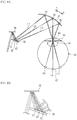
- FIG. 1 illustrates an image projection device in accordance with a first embodiment as viewed from above
- FIG. 2 is an enlarged view of a part of the image projection device in accordance with the first embodiment as viewed from above;
- FIG. 3A is a perspective view illustrating a surface of a reflection mirror included in the image projection device in accordance with the first embodiment
- FIG. 3B is a diagram illustrating a height Z in an X direction of the reflection mirror
- FIG. 4 illustrates contour lines of the reflection mirror included in the image projection device in accordance with the first embodiment
- FIG. 5 illustrates a light path of a laser beam in an image projection device in accordance with a comparative example
- FIG. 6A illustrates a light path of a laser beam in the image projection device in accordance with the first embodiment
- FIG. 6B is an enlarged view of the vicinity of the reflection mirror in FIG. 6A ;
- FIG. 7 illustrates another example of a light beam blocking unit
- FIG. 8A illustrates a light path of a laser beam in an image projection device in accordance with a second embodiment
- FIG. 8B is an enlarged view of the vicinity of a reflection type diffraction grating in FIG. 8A ;
- FIG. 9 illustrates equiphase lines of the reflection type diffraction grating included in the image projection device of the second embodiment
- FIG. 10A illustrates a light path of a laser beam in an image projection device in accordance with a third embodiment
- FIG. 10B is an enlarged view of the vicinity of a transmissive diffraction grating in FIG. 10A ;
- FIG. 11 illustrates equiphase lines of the transmissive diffraction grating included in the image projection device of the third embodiment.
- FIG. 12 is an enlarged view of a part of an image projection device in accordance with a fourth embodiment as viewed from above.
- FIG. 1 illustrates an image projection device in accordance with a first embodiment as viewed from above.
- FIG. 2 is an enlarged view of a part of the image projection device in accordance with the first embodiment as viewed from above.
- a direction in which a light beam that has entered the projection mirror 30 travels in the projection mirror 30 is defined as an X direction, and a direction perpendicular to the X direction in the projection mirror 30 is defined as a Y direction.
- the X direction corresponds to a horizontal direction.
- an image projection device 100 of the first embodiment includes a light source 20 , a lens 22 , a light beam blocking unit 24 , a scan mirror 26 , a reflection mirror 28 , a projection mirror 30 , an image input unit 32 , and a control unit 34 .
- the image projection device 100 of the first embodiment is a spectacle type. Spectacles include a temple 10 and a lens 12 .
- the temple 10 of the spectacles is provided with the light source 20 , the lens 22 , the light beam blocking unit 24 , the scan mirror 26 , and the reflection mirror 28 .
- the lens 12 of the spectacles is provided with the projection mirror 30 .
- the image input unit 32 and the control unit 34 may not be necessarily located in the spectacles, and may be located in an external device (for example, a mobile terminal), and may be located in the temple 10 of the spectacles.
- Image data is input to the image input unit 32 from a camera and/or a recording device that are not illustrated.
- the control unit 34 controls the emission of a laser beam 50 from the light source 20 on the basis of the image data that has been input.
- the light source 20 emits, for example, the laser beam 50 of a single wavelength or the laser beam 50 of a plurality of wavelengths under the control by the control unit 34 . That is, the image data is converted by the light source 20 into the laser beam 50 that is an image light beam.
- the control unit 34 is a processor such as, for example, a central processing unit (CPU).
- AR augmented reality
- the lens 22 is a collimating lens that converts the laser beam 50 emitted from the light source 20 to a substantially parallel laser beam.
- the light beam blocking unit 24 is located on the light path of the laser beam 50 between the lens 22 and the scan mirror 26 .
- the laser beam 50 that has been converted into a substantially parallel light by the lens 22 enters the light beam blocking unit 24 .
- a part of the laser beam 50 that has entered the light beam blocking unit 24 is blocked by the light beam blocking unit 24 , and the remaining part passes through an aperture 36 located in the light beam blocking unit 24 . That is, the light beam blocking unit 24 has the aperture 36 that blocks a part of the laser beam 50 and allows the remaining part to pass therethrough.
- the aperture 36 of the light beam blocking unit 24 has, for example, a substantially circular shape.
- the substantially circular shape is not limited to a complete circular shape, and includes a circular shape of which a part of the outer periphery distorts and an elliptical shape.
- the center of the aperture 36 is substantially aligned with the optical axis of the laser beam 50 .
- the diameter of the aperture 36 is configured so that the diameter of the laser beam 50 when the laser beam 50 that has passed through the light beam blocking unit 24 enters the scan mirror 26 is less than the effective diameter of the scan mirror 26 .
- the diameter of the aperture 36 is equal to or less than the diameter at the intensity of 1/e 2 of the laser beam 50 that has been converted to a substantially parallel light by the lens 22 .
- the scan mirror 26 scans the laser beam 50 that has passed through the light beam blocking unit 24 in the two-dimensional direction to form a projection light for projecting an image onto the retina 62 of the eye ball 60 of the user.
- the scan mirror 26 is, for example, a Micro Electro Mechanical System (MEMS) mirror, and scans the laser beam 50 in the horizontal direction and the vertical direction.
- MEMS Micro Electro Mechanical System
- the directions in which the laser beam 50 is scanned are defined as the X direction and the Y direction, but the laser beam 50 may be scanned in the directions other than the X direction and the Y direction.
- the reflection mirror 28 reflects the laser beam 50 that has been scanned by the scan mirror 26 toward the lens 12 of the spectacles.
- the projection mirror 30 is located on the surface, closer to the eye ball 60 of the user, of the lens 12 of the spectacles.
- the projection mirror 30 irradiates the retina 62 of the eye ball 60 of the user with the laser beam 50 , which has been scanned by the scan mirror 26 and reflected by the reflection mirror 28 , to project an image on the retina 62 . That is, the user recognizes the image by the afterimage effect of the laser beam 50 projected on the retina 62 .
- the projection mirror 30 is designed so that the convergence position of the laser beam 50 scanned by the scan mirror 26 is in the vicinity of a pupil 64 of the eye ball 60 .
- the laser beam 50 enters the projection mirror 30 substantially from the side (i.e., substantially in the X direction).
- the projection mirror 30 is not necessarily in contact with the lens 12 of the spectacles, and may be located in the location from which the laser beam 50 can be emitted to the retina 62 through the pupil 64 of the eye ball 60 .
- only the projection mirror 30 may be provided and the lens 12 of the spectacles may be omitted.
- FIG. 3A is a perspective view illustrating the surface of the reflection mirror included in the image projection device in accordance with the first embodiment
- FIG. 3B illustrates the height Z in the X direction of the reflection mirror.
- the X direction and the Y direction correspond to the X direction and the Y direction in the projection mirror 30 , respectively.
- the height in the reflection mirror 28 corresponds to the Z direction.
- the level difference on the surface of the reflection mirror 28 in the Z direction is enlarged
- the reflection mirror 28 has a substantially planar surface in a region S 0 , a concave surface in a region S 1 , and a convex surface in a region S 2 . Accordingly, the light condensing power is approximately 0 in the region S 0 , positive in the region S 1 , and negative in the region S 2 .
- a ij is a coefficient.
- the coefficients a ij of which i is an odd number is set at a finite value (except 0).
- the light condensing power in the Y direction in the projection mirror 30 is symmetrical about the X-axis.
- the coefficient a ij of which j is an odd number is set at 0.
- the coefficients a 30 and a 12 are set at finite values. This configuration achieves the free curved surface such as FIG. 3A and FIG. 3B .
- the coefficient a 10 and/or a 20 may be set at a finite value.
- the high-order coefficient may be set at a finite value.
- FIG. 4 illustrates contour lines of the reflection mirror included in the image projection device in accordance with the first embodiment.
- the interval between the contour lines is 11.6 ⁇ m.
- Z decreases at farther distances from the center in the +X direction, and Z increases at farther distances from the center in the ⁇ X direction.
- FIG. 4 is a circle because the simulation was conducted on the basis of the retina.
- FIG. 3A corresponds to a part that is cut out as a rectangle from the circle of FIG. 4 .
- FIG. 5 illustrates the light path of a laser beam in the image projection device of the comparative example.
- a light beam L 0 through a light beam L 2 are light beams scanned in the horizontal direction by the scan mirror 26 , and emitted to the projection mirror 30 from the ⁇ X direction.
- the light beam L 0 is a light beam corresponding to the center of the image
- the light beam L 1 and the light beam L 2 are light beams corresponding to the ends of the image.
- the light beam L 0 through the light beam L 2 are respectively reflected by a region R 0 through a region R 2 of the projection mirror 30 .
- the reflected light beam L 0 through the reflected light beam L 2 are converged near the pupil 64 located in the center portion of an iris 66 , pass through a crystalline lens 68 and then reach the retina 62 .
- the region R 0 is a region that reflects the light beam L 0 corresponding to the center of the image.
- the region R 1 is located at the ⁇ X direction side of the region R 0 .
- the region R 2 is located at the +X direction side of the region R 0 .
- the light beam L 0 through the light beam L 2 intersect with each other near the pupil 64 .
- the light beam L 0 reflected by the projection mirror 30 enters the crystalline lens 68 as a substantially parallel light, and focuses near the retina 62 . That is, it is assumed that the focusing position F 0 of the light beam L 0 is in the vicinity of the retina 62 .
- the light beam L 1 reflected by the projection mirror 30 enters the crystalline lens 68 as a diffusion light. Thus, the light beam L 1 focuses at the position behind the retina 62 .
- the light beam L 2 reflected by the projection mirror 30 enters the crystalline lens 68 as a converging light. Thus, the light beam L 2 focuses at the position before the retina 62 .
- the focusing position F 1 of the light beam L 1 is the position farther than the retina 62 from the projection mirror 30 , and the distance between the retina 62 and the focusing position F 1 is D 1 .
- the focusing position F 2 of the light beam L 2 is the position closer to the projection mirror 30 than the retina 62 , and the distance between the focusing position F 2 and the retina 62 is D 2 .
- the reason why the focusing position F 0 through the focusing position F 2 differ as described above is as follows.
- the curvature of the projection mirror 30 differs in the X direction among the region R 0 through the region R 2 and/or the optical path difference among the light beam L 0 through the light beam L 2 is caused.
- the region R 2 has a larger curvature than the region R 1 . That is, the light condensing power in the region R 2 is greater than the light condensing power in the region R 1 .
- the focusing position F 2 is located closer to the light source than the focusing position F 1 is.
- the projection mirror 30 when the projection mirror 30 is arranged in parallel with the face of the user, the light path of the light beam L 2 is longer than that of the light beam L 1 . Accordingly, the focusing position F 2 is located closer to the light source than the focusing position F 1 is.
- the region in which the focusing position greatly deviates from the retina 62 is generated in the image.
- the optical system in the Y direction is substantially symmetrical about the X-axis, and the deviation of the focusing position hardly occurs in the Y direction unlike in the X direction.
- FIG. 6A is a diagram illustrating a light path of the laser beam in the image projection device in accordance with the first embodiment
- FIG. 6B is an enlarged view of the vicinity of the reflection mirror in FIG. 6A .
- the light beam L 0 through the light beam L 2 respectively emitted to the region R 0 through the region R 2 of the projection mirror 30 are respectively reflected by the region S 0 through the region S 2 in the reflection mirror 28 .
- the reflection mirror 28 has a light condensing power of approximately 0 in the region S 0 having a substantially planar surface, has a positive light condensing power in the region S 1 having a concave surface, and has a positive light condensing power in the region S 2 having a convex surface.
- the region R 2 which has a large curvature, of the projection mirror 30 is irradiated with the light beam L 2 reflected by the region S 2 , which has a small light condensing power, of the reflection mirror 28
- the region R 1 which has a small curvature, of the projection mirror 30 is irradiated with the light beam L 1 reflected by the region S 1 , which has a large light condensing power, of the reflection mirror 28 .
- This configuration allows all the light beam L 0 through the light beam L 2 to focus near the retina 62 .
- the surface of the reflection mirror 28 is a free curved surface having a planar surface, a concave surface, and a convex surface corresponding to the change in the curvature of the free curved surface of the projection mirror 30 .
- the concave curved surface and the convex curved surface of the reflection mirror 28 are configured so that the light beam L 1 reflected by the concave surface (the region S 1 ) of the reflection mirror 28 is emitted to the region R 1 of the projection mirror 30 , which has a smaller curvature than the region R 2 of the projection mirror 30 irradiated with the light beam L 2 reflected by the convex surface (the region S 2 ).
- the light condensing power in the region S 1 which reflects the light beam L 1 to be emitted to the region R 1 of the projection mirror 30
- the light condensing power in the region S 2 which reflects the light beam L 2 to be emitted to the region R 2 of the projection mirror 30 , which has a greater light condensing power than the region R 1 .
- the light beam blocking unit 24 having the aperture 36 that blocks a part of the laser beam 50 and allows the remaining part of the laser beam 50 to pass therethrough is located on the light path of the laser beam 50 between the lens 22 and the scan mirror 26 .
- This structure allows the laser beam 50 to enter the scan mirror 26 to have an appropriate diameter, and the optical intensity at the edge of the laser beam 50 (the intensity at the edge of the pupil) is increased.
- the reflection mirror 28 gives an appropriate light condensing power to the laser beam 50 .
- the optical system including the projection mirror 30 is designed under the assumption that the reflection mirror 28 has a planar surface without taking the focusing position F 0 through the focusing position F 2 of the light beam L 0 through the light beam L 2 into consideration. Then, without changing the design of the projection mirror 30 , the surface of the reflection mirror 28 is designed as a free curved surface. Through this design process, the focusing position F 0 through the focusing position F 2 of the light beam L 0 through the light beam L 2 are adjusted.
- the reflection mirror 28 Since the light condensing powers given to the light beam L 0 through the light beam L 2 by the reflection mirror 28 are weak, the reflection mirror 28 hardly affects the trajectories of the light beam L 0 through the light beam L 2 , and the focusing position F 0 through the focusing position F 2 are thus adjusted. Therefore, the optical system can be easily designed.
- FIG. 7 illustrates another example of the light beam blocking unit.
- a region except an effective diameter 44 on a scanning surface 42 of the scan mirror 26 is an absorption part 46 formed of a material that does not reflect the laser beam 50 but absorbs the laser beam 50 , and the scanning surface 42 may function as the light beam blocking unit.
- the light beam blocking unit is located on the light path of the laser beam 50 between the scan mirror 26 and the lens 22 , and the light beam blocking unit may be included in the scanning surface 42 of the scan mirror 26 .
- the region R 1 and the region R 2 of the projection mirror 30 are located at both sides of the position corresponding to the center of the image in the projection mirror 30 (the region R 0 ) in the incident directions of the light beam L 0 through the light beam L 2 .
- the region R 1 is located closer to the optical component (the reflection mirror 28 ) than the region R 2 in the incident directions of the light beam L 0 through the light beam L 2 .
- the region R 0 through the region R 2 are arranged in this manner, in the comparative example, the deviation of the focusing position F 0 through the focusing position F 2 from the retina 62 is large as illustrated in FIG. 5 .
- the light condensing powers of the region S 0 through the region S 2 of the reflection mirror 28 are preferably made to be different.
- the distance between the region R 1 and the region R 2 in the projection mirror 30 is greater than the distance between the region S 1 and the region S 2 in the reflection mirror 28 .
- the light condensing powers of the region R 1 and the region R 2 are made to be largely different.
- the light paths of the light beam L 0 through the light beam L 2 largely differ.
- This configuration causes the large deviation of the focusing position F 1 through the focusing position F 2 from the retina 62 .
- the light condensing powers in the region S 1 and the region S 2 of the reflection mirror 28 are preferably made to be different.
- the distance D 1 between the focusing position F 1 at which the light beam L 1 focuses and the retina 62 and the distance D 2 between the focusing position F 2 at which the light beam L 2 focuses and the retina 62 are respectively smaller than the distances D 1 and D 2 when the light condensing powers in the regions S 1 and the region S 2 of the reflection mirror 28 are assumed to be the same. Accordingly, the focusing position F 0 through the focusing position F 2 of the light beam L 0 through the light beam L 2 can be configured to be in the vicinity of the retina 62 .
- the light condensing powers of the region S 1 and the region S 2 are configured by configuring the curvature in the region S 1 to be greater than the curvature in the region S 2 .
- This configuration allows the light condensing power in the region S 1 to be greater than the light condensing power in the region S 2 .
- the curvature of the concave surface is defined as being positive as in the region S 1 and the curvature of the convex surface is defined as being negative as in the region S 2 as illustrated in FIG. 3A and FIG. 3B .
- the use of the reflection mirror 28 allows the light condensing powers of the light beams L 0 through the light beams L 2 of the individual wavelengths to be set with use of a single curved surface.
- FIG. 8A illustrates a light path of a laser beam in the image projection device in accordance with the second embodiment
- FIG. 8B is an enlarged view of the vicinity of the reflection type diffraction grating in FIG. 8A . As illustrated in FIG. 8A and FIG.
- the image projection device of the second embodiment includes the reflection type diffraction grating 38 instead of the reflection mirror 28 , and the light beam L 0 through the light beam L 2 scanned by the scan mirror 26 are reflected by the region S 0 through the region S 2 of the reflection type diffraction grating 38 and then enter the projection mirror 30 .
- FIG. 9 illustrates equiphase lines of the reflection type diffraction grating included in the image projection device in accordance with the second embodiment.
- the interval between lines is 50 ⁇ 2 ⁇ rad.
- the interval between equiphase lines corresponds to the pitch of the reflection type diffraction grating 38 .
- the use of the reflection type diffraction grating 38 also allows the light condensing power of the region S 0 to be approximately 0, the light condensing power of the region S 1 to be positive, and the light condensing power of the region S 2 to be negative.
- FIG. 10A illustrates a light path of a laser beam in the image projection device in accordance with the third embodiment
- FIG. 10B is an enlarged view of the vicinity of the transmissive diffraction grating in FIG. 10A . As illustrated in FIG. 10A and FIG.
- the image projection device of the third embodiment includes the transmissive diffraction grating 40 instead of the reflection mirror 28 , and the light beam L 0 through the light beam L 2 scanned by the scan mirror 26 respectively pass through the region S 0 through the region S 2 of the transmissive diffraction grating 40 and then enter the projection mirror 30 .
- FIG. 11 illustrates equiphase lines of the transmissive diffraction grating of the image projection device in accordance with the third embodiment.
- the interval between lines is 7.5 ⁇ 2 ⁇ rad.
- the interval between the equiphase lines corresponds to the pitch of the transmissive diffraction grating 40 .
- the use of the transmissive diffraction grating 40 also allows the light condensing power of the region S 0 to be approximately 0, the light condensing power of the region S 1 to be positive, and the light condensing power of the region S 2 to be negative.
- the optical component that reflects the light beam L 0 through the light beam L 2 scanned by the scan mirror 26 or allows the light beam L 0 through the light beam L 2 scanned by the scan mirror 26 to pass therethrough may be the reflection mirror 28 , the reflection type diffraction grating 38 , or the transmissive diffraction grating 40 .
- the pitch in the region S 1 is configured to be greater than the pitch in the region S 2 . This configuration allows the light condensing power in the region S 1 to be greater than the light condensing power in the region S 2 .
- the use of the reflection type diffraction grating 38 or the transmissive diffraction grating 40 as the optical component allows the light condensing power to be more precisely configured.
- the light condensing powers of the reflection type diffraction grating 38 and the transmissive diffraction grating 40 depend on the wavelength.
- the light beam L 0 through the light beam L 2 are preferably a light of a single wavelength.
- diffractive elements corresponding to respective wavelengths are preferably stacked.
- the reflection type diffraction grating 38 has a phase distribution with different phase pitches corresponding to the change in the curvature of the free curved surface of the projection mirror 30 .
- the phase pitches of the reflection type diffraction grating 38 are configured so that the light beam L 1 reflected by the region S 1 , having a wide phase pitch, of the reflection type diffraction grating 38 is emitted to the region R 1 of the projection mirror 30 of which the curvature is less than the curvature of the region R 2 of the projection mirror 30 irradiated with the light beam L 2 reflected by the region S 2 having a narrow phase pitch.
- This configuration allows the light beam L 0 through the light beam L 2 to focus near the retina 62 as illustrated in FIG.
- the diameter of the laser beam 50 to enter the scan mirror 26 is configured to be an appropriate diameter, and the optical intensity at the edge of the laser beam 50 (the intensity at the edge of the eye) is increased. Thus, a good image is provided to the user.
- the transmissive diffraction grating 40 has a phase distribution with different pitches corresponding to the change in the curvature of the free curved surface of the projection mirror 30 .
- the phase pitches of the transmissive diffraction grating 40 are configured so that the light beam L 1 that has passed through the region S 1 , having a wide phase pitch, of the transmissive diffraction grating 40 is emitted to the region R 1 of the projection mirror 30 of which the curvature is less than the curvature of the region R 2 of the projection mirror 30 irradiated with the light beam L 2 that has passed through the region S 2 having a narrow phase pitch.
- This configuration allows the light beam L 0 through the light beam L 2 to focus near the retina 62 as illustrated in FIG. 10A .
- the diameter of the laser beam 50 to enter the scan mirror 26 is configured to be an appropriate diameter, and the optical intensity at the edge of the laser beam 50 (the intensity at the edge of the pupil) is increased. Therefore, a good image is provided to the user.
- the projection mirror 30 may be a diffractive element.
- the light condensing power of the projection mirror 30 in the region R 1 is preferably less than the light condensing power of the projection mirror 30 in the region R 2 .
- the projection mirror 30 may be a half mirror that allows the light in the eye direction of the eye ball 60 to pass therethrough, or may be a total reflection mirror that allows no light to pass therethrough.
- the projection mirror 30 is a half mirror, the real image in the eye direction is allowed to pass through the projection mirror 30 and to be recognized together with the image by the laser beam 50 , while when the projection mirror 30 is a total reflection mirror, only the image by the laser beam 50 can be visually recognized.
- the optical systems of the light beam L 0 through the light beam L 2 are substantially symmetrical about the Y-axis direction.
- the light condensing powers at a pair of positions in the optical component corresponding to a pair of positions in the projection mirror 30 that is symmetrical with respect to the line that passes through the position corresponding to the center of the image in the projection mirror 30 and extending in the X direction are preferably practically the same.
- FIG. 12 is an enlarged view of a part of an image projection device in accordance with a fourth embodiment as viewed from above.
- an image projection device 400 of the fourth embodiment includes a neutral density filter 70 , which reduces the intensity of the laser beam 50 , on the light path of the laser beam 50 between the lens 22 and the scan mirror 26 in addition to the light beam blocking unit 24 .
- the neutral density filter 70 is, for example, an optical coated resin member.
- Other structures are the same as the image projection device 100 of the first embodiment.
- the neutral density filter 70 is located on the light path of the laser beam 50 between the light source 20 and the eye ball 60 . There is a limit to adjusting the intensity of the laser beam 50 by electrically controlling the light source 20 . However, the provision of the neutral density filter 70 in the light path of the laser beam 50 allows the laser beam 50 with an appropriate intensity to be emitted to the retina 62 . This configuration allows an image with an appropriate brightness to be provided to the user.
- the neutral density filter 70 is located further downstream than the light beam blocking unit 24 in the traveling direction of the laser beam 50 , but the neutral density filter 70 may be located further upstream than the light beam blocking unit 24 .
- the neutral density filter 70 is located between the light source 20 and the scan mirror 26 , but may be located at any position between the light source 20 and the eye ball 60 as long as it is located on the light path of the laser beam 50 .
- the neutral density filter 70 may be located between the scan mirror 26 and the reflection mirror 28 , between the reflection mirror 28 and the projection mirror 30 , between the projection mirror 30 and the eye ball 60 , on the scanning surface of the scan mirror 26 , on the reflection surface of the reflection mirror 28 , the reflection surface of the projection mirror 30 , or at two or more of these locations.
- the neutral density filter 70 is preferably located between the lens 22 and the scan mirror 26 as in the fourth embodiment. This is because since the laser beam 50 that has been converted into a substantially parallel light by the lens 22 and has a relatively large diameter passes through the neutral density filter 70 , even when the neutral density filter 70 has an in-plane distribution, the effect of the in-plane distribution is reduced.
- the neutral density filter 70 when the neutral density filter 70 is located further downstream than the scan mirror 26 in the traveling direction of the laser beam 50 , since the laser beam 50 that has been scanned by the scan mirror 26 across the wide area of the neutral density filter 70 enters the neutral density filter 70 , the effect of the in-plane distribution of the neutral density filter 70 is large. However, the neutral density filter 70 located between the lens 22 and the scan mirror 26 causes the laser beam 50 to enter only a certain area of the neutral density filter 70 , thereby reducing the effect of the in-plane distribution.
- the first through fourth embodiments have described, as an example, a case where the image projection device is a spectacle-type HMD, but the image projection device may be other than the HMD.
- the image projection device may be other than the HMD.
- a case where an image is projected on the retina 62 of one of the eye balls 60 has been described, but the image may be projected onto the retinas 62 of both eye balls 60 .
- the scan unit is the scan mirror 26 has been described as an example, but the scan mirror may be other components as long as it can scan a light beam.
- the scan unit may be other components such as Potassium Tantalum Niobium Oxide (KTN) crystal that is an electro-optic material.
- KTN Potassium Tantalum Niobium Oxide
- the laser beam has been described as an example of the light beam, but the light beam may be a light other than the laser beam.
- both the light condensing powers in the region S 1 and the region S 2 of the optical component may be positive or negative.
- a case where the direction in which the light beam L 0 through the light beam L 2 enter the projection mirror 30 is the horizontal direction has been described, but the light beam L 0 through the light beam L 2 may enter the projection mirror 30 in the vertical direction or in an oblique direction.
Landscapes
- Physics & Mathematics (AREA)
- Optics & Photonics (AREA)
- General Physics & Mathematics (AREA)
- Engineering & Computer Science (AREA)
- Multimedia (AREA)
- Signal Processing (AREA)
- Mechanical Optical Scanning Systems (AREA)
- Transforming Electric Information Into Light Information (AREA)
Abstract
Description
Z=Σa ij ×X 1 ×Y j
Claims (12)
Applications Claiming Priority (3)
| Application Number | Priority Date | Filing Date | Title |
|---|---|---|---|
| JP2016201864A JP6209662B1 (en) | 2016-10-13 | 2016-10-13 | Image projection device |
| JP2016-201864 | 2016-10-13 | ||
| PCT/JP2017/034753 WO2018070236A1 (en) | 2016-10-13 | 2017-09-26 | Image projection device |
Publications (2)
| Publication Number | Publication Date |
|---|---|
| US20200014891A1 US20200014891A1 (en) | 2020-01-09 |
| US10924716B2 true US10924716B2 (en) | 2021-02-16 |
Family
ID=59997758
Family Applications (1)
| Application Number | Title | Priority Date | Filing Date |
|---|---|---|---|
| US16/340,124 Active US10924716B2 (en) | 2016-10-13 | 2017-09-26 | Image projection device |
Country Status (4)
| Country | Link |
|---|---|
| US (1) | US10924716B2 (en) |
| JP (1) | JP6209662B1 (en) |
| CN (1) | CN109804296B (en) |
| WO (1) | WO2018070236A1 (en) |
Families Citing this family (11)
| Publication number | Priority date | Publication date | Assignee | Title |
|---|---|---|---|---|
| JP2020502573A (en) * | 2016-12-15 | 2020-01-23 | フサオ イシイ | Optical system of wearable display using laser beam scanner |
| US10698204B1 (en) * | 2017-10-16 | 2020-06-30 | Facebook Technologies, Llc | Immersed hot mirrors for illumination in eye tracking |
| JP2019154815A (en) | 2018-03-13 | 2019-09-19 | 株式会社リコー | Device for detecting inclination position of eyeball, display device and optometry device |
| JP7052577B2 (en) * | 2018-06-07 | 2022-04-12 | 株式会社リコー | Optical equipment, video display equipment, and optometry equipment |
| JP7078985B2 (en) * | 2018-06-12 | 2022-06-01 | 株式会社Qdレーザ | Image projection device |
| WO2020121814A1 (en) * | 2018-12-11 | 2020-06-18 | 株式会社Qdレーザ | Image display device and relay optical system |
| KR102708994B1 (en) * | 2019-06-27 | 2024-09-23 | 가부시키가이샤 리코 | Optical devices, image display devices and ophthalmic devices |
| KR20250172729A (en) * | 2019-09-16 | 2025-12-09 | 루머스 리미티드 | Compact projector for head-mounted displays |
| JP7540364B2 (en) * | 2021-02-26 | 2024-08-27 | セイコーエプソン株式会社 | Optical module and head-mounted display device |
| JP7608910B2 (en) * | 2021-03-22 | 2025-01-07 | 株式会社リコー | Optical device, retinal projection display device, and head-mounted display device |
| WO2023042346A1 (en) * | 2021-09-16 | 2023-03-23 | 株式会社東芝 | Optical device, information processing method, and program |
Citations (23)
| Publication number | Priority date | Publication date | Assignee | Title |
|---|---|---|---|---|
| JPS5216761B2 (en) | 1974-07-31 | 1977-05-11 | ||
| JPH11109882A (en) | 1997-10-06 | 1999-04-23 | Minolta Co Ltd | Video display device |
| JPH11160650A (en) | 1997-11-27 | 1999-06-18 | Nec Corp | Picture display device |
| WO2004029693A1 (en) | 2002-09-24 | 2004-04-08 | Nikon Corp | Image display unit and projection optical system |
| JP2006013127A (en) | 2004-06-25 | 2006-01-12 | Sony Corp | Light source device and display device |
| JP2006251509A (en) | 2005-03-11 | 2006-09-21 | Brother Ind Ltd | Image display device |
| JP2008046253A (en) | 2006-08-11 | 2008-02-28 | Canon Inc | Image display device |
| US20080212295A1 (en) | 2007-03-01 | 2008-09-04 | Hon Hai Precision Industry Co., Ltd. | Retention device for securing expansion card shields |
| US20080225291A1 (en) * | 2007-03-16 | 2008-09-18 | Konica Minolta Sensing, Inc. | Concave diffraction grating device, reflective dispersion device, and spectral device |
| US20090122545A1 (en) * | 2007-11-12 | 2009-05-14 | Seiko Epson Corporation | Light source device and image display apparatus |
| JP2009258686A (en) | 2008-03-28 | 2009-11-05 | Panasonic Corp | Image display device and image display method |
| CN101589327A (en) | 2007-09-26 | 2009-11-25 | 松下电器产业株式会社 | Beam scan type display device, its display method, program, and integrated circuit |
| JP2010211148A (en) | 2009-03-12 | 2010-09-24 | Brother Ind Ltd | Image display apparatus |
| WO2010116726A1 (en) | 2009-04-09 | 2010-10-14 | パナソニック株式会社 | Beam-scanning display device |
| JP2011215194A (en) | 2010-03-31 | 2011-10-27 | Brother Industries Ltd | Direct viewing type image display device |
| US20130265623A1 (en) * | 2012-04-10 | 2013-10-10 | Panasonic Corporation | Computer generated hologram type display device |
| CN103592762A (en) | 2012-08-17 | 2014-02-19 | 精工爱普生株式会社 | Image display device and head-mounted image display device |
| JP2014048498A (en) | 2012-08-31 | 2014-03-17 | Olympus Corp | Eccentric optical system, image projection device using eccentric optical system, and image pickup device using eccentric optical system |
| JP2015111231A (en) | 2013-05-31 | 2015-06-18 | 株式会社Qdレーザ | Image projection apparatus and projection apparatus |
| US20150205126A1 (en) | 2013-11-27 | 2015-07-23 | Magic Leap, Inc. | Virtual and augmented reality systems and methods |
| WO2016091743A1 (en) | 2014-12-12 | 2016-06-16 | Carl Zeiss Smart Optics Gmbh | Display devices |
| WO2017056802A1 (en) | 2015-09-29 | 2017-04-06 | 株式会社Qdレーザ | Image projection device |
| US20190137857A1 (en) * | 2016-06-09 | 2019-05-09 | Qd Laser, Inc. | Image projection system, image projection device, image projection method, image projection program, and server device |
-
2016
- 2016-10-13 JP JP2016201864A patent/JP6209662B1/en active Active
-
2017
- 2017-09-26 US US16/340,124 patent/US10924716B2/en active Active
- 2017-09-26 WO PCT/JP2017/034753 patent/WO2018070236A1/en not_active Ceased
- 2017-09-26 CN CN201780062365.9A patent/CN109804296B/en active Active
Patent Citations (32)
| Publication number | Priority date | Publication date | Assignee | Title |
|---|---|---|---|---|
| JPS5216761B2 (en) | 1974-07-31 | 1977-05-11 | ||
| JPH11109882A (en) | 1997-10-06 | 1999-04-23 | Minolta Co Ltd | Video display device |
| JPH11160650A (en) | 1997-11-27 | 1999-06-18 | Nec Corp | Picture display device |
| US6081304A (en) | 1997-11-27 | 2000-06-27 | Nec Corporation | Image display apparatus |
| WO2004029693A1 (en) | 2002-09-24 | 2004-04-08 | Nikon Corp | Image display unit and projection optical system |
| US20060072215A1 (en) | 2002-09-24 | 2006-04-06 | Kenji Nishi | Image display unit and projection optical system |
| JP2006013127A (en) | 2004-06-25 | 2006-01-12 | Sony Corp | Light source device and display device |
| JP2006251509A (en) | 2005-03-11 | 2006-09-21 | Brother Ind Ltd | Image display device |
| JP2008046253A (en) | 2006-08-11 | 2008-02-28 | Canon Inc | Image display device |
| US20080212295A1 (en) | 2007-03-01 | 2008-09-04 | Hon Hai Precision Industry Co., Ltd. | Retention device for securing expansion card shields |
| US20080225291A1 (en) * | 2007-03-16 | 2008-09-18 | Konica Minolta Sensing, Inc. | Concave diffraction grating device, reflective dispersion device, and spectral device |
| CN101589327A (en) | 2007-09-26 | 2009-11-25 | 松下电器产业株式会社 | Beam scan type display device, its display method, program, and integrated circuit |
| US20100060551A1 (en) | 2007-09-26 | 2010-03-11 | Keiji Sugiyama | Beam scanning-type display device, method, program and integrated circuit |
| US20090122545A1 (en) * | 2007-11-12 | 2009-05-14 | Seiko Epson Corporation | Light source device and image display apparatus |
| JP2009258686A (en) | 2008-03-28 | 2009-11-05 | Panasonic Corp | Image display device and image display method |
| US20090316115A1 (en) | 2008-03-28 | 2009-12-24 | Tatsuo Itoh | Image display apparatus and image display method |
| JP2010211148A (en) | 2009-03-12 | 2010-09-24 | Brother Ind Ltd | Image display apparatus |
| WO2010116726A1 (en) | 2009-04-09 | 2010-10-14 | パナソニック株式会社 | Beam-scanning display device |
| US20110102874A1 (en) | 2009-04-09 | 2011-05-05 | Keiji Sugiyama | Beam scanning display apparatus |
| JP2011215194A (en) | 2010-03-31 | 2011-10-27 | Brother Industries Ltd | Direct viewing type image display device |
| US20130265623A1 (en) * | 2012-04-10 | 2013-10-10 | Panasonic Corporation | Computer generated hologram type display device |
| CN103592762A (en) | 2012-08-17 | 2014-02-19 | 精工爱普生株式会社 | Image display device and head-mounted image display device |
| US20140049831A1 (en) | 2012-08-17 | 2014-02-20 | Seiko Epson Corporation | Image display device and head-mounted image display device |
| JP2014048498A (en) | 2012-08-31 | 2014-03-17 | Olympus Corp | Eccentric optical system, image projection device using eccentric optical system, and image pickup device using eccentric optical system |
| JP2015111231A (en) | 2013-05-31 | 2015-06-18 | 株式会社Qdレーザ | Image projection apparatus and projection apparatus |
| CN105264423A (en) | 2013-05-31 | 2016-01-20 | Qd激光公司 | Image projection device and projection device |
| US20160103324A1 (en) * | 2013-05-31 | 2016-04-14 | Qd Laser Inc. | Image projection device and projection device |
| US20150205126A1 (en) | 2013-11-27 | 2015-07-23 | Magic Leap, Inc. | Virtual and augmented reality systems and methods |
| CN105934902A (en) | 2013-11-27 | 2016-09-07 | 奇跃公司 | Virtual and augmented reality systems and methods |
| WO2016091743A1 (en) | 2014-12-12 | 2016-06-16 | Carl Zeiss Smart Optics Gmbh | Display devices |
| WO2017056802A1 (en) | 2015-09-29 | 2017-04-06 | 株式会社Qdレーザ | Image projection device |
| US20190137857A1 (en) * | 2016-06-09 | 2019-05-09 | Qd Laser, Inc. | Image projection system, image projection device, image projection method, image projection program, and server device |
Non-Patent Citations (4)
| Title |
|---|
| International Search Report of the International Searching Authority for International Application No. PCT/JP2017/034753 dated Dec. 13, 2017 (10 sheets). |
| Office Action of Chinese Patent Application No. 201780062365.9 dated Nov. 9, 2020 (7 sheets, 7 sheets translation, 14 sheets total). |
| Office Action of Japanese Patent Application No. 2016-201864: Decision to Grant a Patent dated Aug. 29, 2017 (3 pages, 3 pages translation, 6 pages total). |
| Office Action of Japanese Patent Application No. 2016-201864: Notification of Reasons for Refusal dated Jun. 27, 2017 (5 pages, 5 pages translation, 10 pages total). |
Also Published As
| Publication number | Publication date |
|---|---|
| JP6209662B1 (en) | 2017-10-04 |
| JP2018063365A (en) | 2018-04-19 |
| US20200014891A1 (en) | 2020-01-09 |
| CN109804296B (en) | 2021-05-18 |
| WO2018070236A1 (en) | 2018-04-19 |
| CN109804296A (en) | 2019-05-24 |
Similar Documents
| Publication | Publication Date | Title |
|---|---|---|
| US10924716B2 (en) | Image projection device | |
| US12292571B2 (en) | Tilting array based display | |
| US10627631B2 (en) | Image projection device and projection device | |
| US10365548B2 (en) | Systems, devices, and methods for focusing laser projectors | |
| US10921598B2 (en) | Image projection device | |
| EP3690517A1 (en) | Image projection device | |
| CN107807448B (en) | Virtual reality display optical system | |
| CN107797290B (en) | Virtual reality display optical system and virtual reality glasses | |
| US20240329408A1 (en) | Method and system for performing optical imaging in augmented reality devices | |
| JP6209705B2 (en) | Image projection device | |
| CN113534477A (en) | Optical assembly, display system and manufacturing method | |
| KR102751192B1 (en) | Anamorphic optical system and display apparatus including the same | |
| JP2022151880A (en) | image projection device | |
| CN114280776A (en) | Optical assembly, near-to-eye display device and manufacturing method | |
| JP2021067895A (en) | Laser scanning device | |
| KR102884536B1 (en) | Display system with variable beam expansion for multiple lasers | |
| JP2024534954A (en) | Liquid crystal eyebox guidance in a waveguide eyewear display |
Legal Events
| Date | Code | Title | Description |
|---|---|---|---|
| FEPP | Fee payment procedure |
Free format text: ENTITY STATUS SET TO UNDISCOUNTED (ORIGINAL EVENT CODE: BIG.); ENTITY STATUS OF PATENT OWNER: LARGE ENTITY |
|
| AS | Assignment |
Owner name: QD LASER, INC., JAPAN Free format text: ASSIGNMENT OF ASSIGNORS INTEREST;ASSIGNORS:SUZUKI, MAKOTO;HASEGAWA, KINYA;REEL/FRAME:049356/0433 Effective date: 20190204 |
|
| STPP | Information on status: patent application and granting procedure in general |
Free format text: RESPONSE TO NON-FINAL OFFICE ACTION ENTERED AND FORWARDED TO EXAMINER |
|
| STPP | Information on status: patent application and granting procedure in general |
Free format text: AWAITING TC RESP., ISSUE FEE NOT PAID |
|
| STPP | Information on status: patent application and granting procedure in general |
Free format text: PUBLICATIONS -- ISSUE FEE PAYMENT VERIFIED |
|
| STCF | Information on status: patent grant |
Free format text: PATENTED CASE |
|
| MAFP | Maintenance fee payment |
Free format text: PAYMENT OF MAINTENANCE FEE, 4TH YEAR, LARGE ENTITY (ORIGINAL EVENT CODE: M1551); ENTITY STATUS OF PATENT OWNER: LARGE ENTITY Year of fee payment: 4 |