US10909747B2 - Systems and methods for providing immersive graphical interfaces - Google Patents
Systems and methods for providing immersive graphical interfaces Download PDFInfo
- Publication number
- US10909747B2 US10909747B2 US15/938,317 US201815938317A US10909747B2 US 10909747 B2 US10909747 B2 US 10909747B2 US 201815938317 A US201815938317 A US 201815938317A US 10909747 B2 US10909747 B2 US 10909747B2
- Authority
- US
- United States
- Prior art keywords
- virtual environment
- virtual
- planar element
- alternate
- environment
- Prior art date
- Legal status (The legal status is an assumption and is not a legal conclusion. Google has not performed a legal analysis and makes no representation as to the accuracy of the status listed.)
- Active, expires
Links
Images


Classifications
-
- G—PHYSICS
- G06—COMPUTING; CALCULATING OR COUNTING
- G06F—ELECTRIC DIGITAL DATA PROCESSING
- G06F3/00—Input arrangements for transferring data to be processed into a form capable of being handled by the computer; Output arrangements for transferring data from processing unit to output unit, e.g. interface arrangements
- G06F3/01—Input arrangements or combined input and output arrangements for interaction between user and computer
- G06F3/011—Arrangements for interaction with the human body, e.g. for user immersion in virtual reality
- G06F3/013—Eye tracking input arrangements
-
- G—PHYSICS
- G06—COMPUTING; CALCULATING OR COUNTING
- G06F—ELECTRIC DIGITAL DATA PROCESSING
- G06F3/00—Input arrangements for transferring data to be processed into a form capable of being handled by the computer; Output arrangements for transferring data from processing unit to output unit, e.g. interface arrangements
- G06F3/01—Input arrangements or combined input and output arrangements for interaction between user and computer
- G06F3/011—Arrangements for interaction with the human body, e.g. for user immersion in virtual reality
-
- G—PHYSICS
- G06—COMPUTING; CALCULATING OR COUNTING
- G06T—IMAGE DATA PROCESSING OR GENERATION, IN GENERAL
- G06T15/00—3D [Three Dimensional] image rendering
- G06T15/10—Geometric effects
- G06T15/20—Perspective computation
-
- G—PHYSICS
- G06—COMPUTING; CALCULATING OR COUNTING
- G06F—ELECTRIC DIGITAL DATA PROCESSING
- G06F3/00—Input arrangements for transferring data to be processed into a form capable of being handled by the computer; Output arrangements for transferring data from processing unit to output unit, e.g. interface arrangements
- G06F3/01—Input arrangements or combined input and output arrangements for interaction between user and computer
- G06F3/048—Interaction techniques based on graphical user interfaces [GUI]
- G06F3/0481—Interaction techniques based on graphical user interfaces [GUI] based on specific properties of the displayed interaction object or a metaphor-based environment, e.g. interaction with desktop elements like windows or icons, or assisted by a cursor's changing behaviour or appearance
- G06F3/04815—Interaction with a metaphor-based environment or interaction object displayed as three-dimensional, e.g. changing the user viewpoint with respect to the environment or object
-
- G—PHYSICS
- G06—COMPUTING; CALCULATING OR COUNTING
- G06F—ELECTRIC DIGITAL DATA PROCESSING
- G06F3/00—Input arrangements for transferring data to be processed into a form capable of being handled by the computer; Output arrangements for transferring data from processing unit to output unit, e.g. interface arrangements
- G06F3/01—Input arrangements or combined input and output arrangements for interaction between user and computer
- G06F3/048—Interaction techniques based on graphical user interfaces [GUI]
- G06F3/0484—Interaction techniques based on graphical user interfaces [GUI] for the control of specific functions or operations, e.g. selecting or manipulating an object, an image or a displayed text element, setting a parameter value or selecting a range
- G06F3/04845—Interaction techniques based on graphical user interfaces [GUI] for the control of specific functions or operations, e.g. selecting or manipulating an object, an image or a displayed text element, setting a parameter value or selecting a range for image manipulation, e.g. dragging, rotation, expansion or change of colour
-
- G—PHYSICS
- G06—COMPUTING; CALCULATING OR COUNTING
- G06T—IMAGE DATA PROCESSING OR GENERATION, IN GENERAL
- G06T15/00—3D [Three Dimensional] image rendering
- G06T15/005—General purpose rendering architectures
-
- G—PHYSICS
- G06—COMPUTING; CALCULATING OR COUNTING
- G06T—IMAGE DATA PROCESSING OR GENERATION, IN GENERAL
- G06T19/00—Manipulating 3D models or images for computer graphics
- G06T19/006—Mixed reality
-
- G—PHYSICS
- G06—COMPUTING; CALCULATING OR COUNTING
- G06F—ELECTRIC DIGITAL DATA PROCESSING
- G06F2203/00—Indexing scheme relating to G06F3/00 - G06F3/048
- G06F2203/01—Indexing scheme relating to G06F3/01
- G06F2203/012—Walk-in-place systems for allowing a user to walk in a virtual environment while constraining him to a given position in the physical environment
-
- G—PHYSICS
- G06—COMPUTING; CALCULATING OR COUNTING
- G06T—IMAGE DATA PROCESSING OR GENERATION, IN GENERAL
- G06T2200/00—Indexing scheme for image data processing or generation, in general
- G06T2200/24—Indexing scheme for image data processing or generation, in general involving graphical user interfaces [GUIs]
-
- H—ELECTRICITY
- H04—ELECTRIC COMMUNICATION TECHNIQUE
- H04N—PICTORIAL COMMUNICATION, e.g. TELEVISION
- H04N13/00—Stereoscopic video systems; Multi-view video systems; Details thereof
- H04N13/30—Image reproducers
- H04N13/332—Displays for viewing with the aid of special glasses or head-mounted displays [HMD]
- H04N13/344—Displays for viewing with the aid of special glasses or head-mounted displays [HMD] with head-mounted left-right displays
Definitions
- Virtual reality systems may be the beginning of a thrilling experience, one that may be more immersive than almost any other digital entertainment or simulation experience available today.
- Virtual reality systems may enable users to travel through space and time, interact with friends in a three-dimensional world, or play video games in a radically redefined way.
- Virtual reality systems may also be used for purposes other than recreation—governments may use them for military training simulations, doctors may use them to practice surgery, and engineers may use them as visualization aids.
- a graphical interface for a virtual reality system may provide an immersive three-dimensional environment with apparent views into an alternate three-dimensional environment via a tile (e.g., acting as a user interface element), creating a parallax effect between the immersive three-dimensional environment and the alternate three-dimensional environment as shown via the tile.
- a tile e.g., acting as a user interface element
- a computer-implemented method for providing immersive graphical interfaces may include (i) associating a planar element within a virtual environment with an alternate virtual environment and (ii) rendering the virtual environment such that (A) the alternate virtual environment is framed within the planar element, (B) at least one rendered element of the alternate virtual environment renders at a distal depth beyond a proximal depth of the planar element within the virtual environment, and (C) altering a viewpoint within the virtual environment relative to a position of the planar element within the virtual environment produces a parallax effect between the virtual environment and the rendered element of the alternate virtual environment due at least in part to the rendered element of the alternate virtual environment being rendered at the distal depth beyond the proximal depth of the planar element within the virtual environment.
- the computer-implemented method may render the virtual environment within a virtual reality system.
- the virtual environment may include a graphical user interface.
- the planar element may include an element of the graphical user interface.
- the method may further include (i) receiving, via the graphical user interface, an input directed to the planar element and (ii) performing an action relating to a virtual reality application that includes the alternate virtual environment, where the action is responsive to (A) identifying an association between the planar element and the alternate virtual environment and (B) the input directed to the planar element.
- the action may replace the virtual environment with the alternate virtual environment.
- the alternate virtual environment may be framed within the planar element
- the planar element may be positioned within the virtual environment, such that elements of the virtual environment may be obscured by the planar element.
- altering the viewpoint within the virtual environment relative to the position of the planar element within the virtual environment may reveal a portion of the virtual environment otherwise obscured by the planar element.
- altering the viewpoint within the virtual environment relative to the position of the planar element within the virtual environment may include altering the viewpoint within the virtual environment. Additionally or alternatively, altering the viewpoint within the virtual environment relative to the position of the planar element within the virtual environment may include altering the position of the planar element within the virtual environment.
- the computer-implemented method may further include receiving, via a virtual reality interface, an input to manipulate the planar element.
- altering the viewpoint within the virtual environment relative to the position of the planar element within the virtual environment may include manipulating the planar element in response to the input.
- the input may include an input to manually grasp the planar element. Additionally or alternatively, the input may include a hand movement after manually grasping the planar element.
- a corresponding system for providing immersive graphical interfaces may include several modules stored in memory, including an association module and a rendering module, and one or more physical processors that execute the modules.
- the association module may associate a planar element within a virtual environment with an alternate virtual environment.
- the rendering module may render the virtual environment such that (i) the alternate virtual environment is framed within the planar element, (i) at least one rendered element of the alternate virtual environment renders at a distal depth beyond a proximal depth of the planar element within the virtual environment, and (i) altering a viewpoint within the virtual environment relative to a position of the planar element within the virtual environment produces a parallax effect between the virtual environment and the rendered element of the alternate virtual environment due at least in part to the rendered element of the alternate virtual environment being rendered at the distal depth beyond the proximal depth of the planar element within the virtual environment.
- a computer-readable medium may include one or more computer-executable instructions that, when executed by at least one processor of a computing device, may cause the computing device to (i) associate a planar element within a virtual environment with an alternate virtual environment and (ii) render the virtual environment such that (A) the alternate virtual environment is framed within the planar element, (B) at least one rendered element of the alternate virtual environment renders at a distal depth beyond a proximal depth of the planar element within the virtual environment, and (C) altering a viewpoint within the virtual environment relative to a position of the planar element within the virtual environment produces a parallax effect between the virtual environment and the rendered element of the alternate virtual environment due at least in part to the rendered element of the alternate virtual environment being rendered at the distal depth beyond the proximal depth of the planar element within the virtual environment.
- FIG. 1 is a flow diagram of an exemplary method for providing immersive graphical interfaces.
- FIG. 2 is an illustration of an exemplary immersive graphical environment showing an alternate virtual environment.
- FIG. 3 provides another view of the immersive graphical environment.
- FIG. 4 provides an additional view of the immersive graphical environment.
- FIG. 5 provides a further view of the immersive graphical environment.
- FIG. 6 provides another view of the immersive graphical environment.
- FIG. 7 is an illustration of an exemplary immersive graphical environment showing an alternate virtual environment.
- FIG. 8 shows the immersive graphical environment of FIG. 7 in the process of being replaced by the alternate virtual environment of FIG. 7 .
- FIG. 9 shows the immersive graphical environment of FIG. 7 replaced with the alternate virtual environment shown in FIG. 7 .
- FIG. 10 is an illustration of an exemplary immersive graphical environment showing an alternate virtual environment.
- FIG. 11 shows the immersive graphical environment of FIG. 10 with a different view of the alternate virtual environment of FIG. 10 .
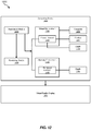
- FIG. 12 is a block diagram of an exemplary system for providing immersive graphical interfaces.
- a graphical interface for a virtual reality system that provides an immersive three-dimensional environment with apparent views into alternate three-dimensional environments.
- a planar element e.g., a tile acting as a user interface element
- the tile frames a view of an alternate virtual environment.
- the view of the alternate virtual environment changes according to the viewpoint of the user and/or according to the position of the tile. Because the effective depth of the alternate virtual environment as seen through the tile is greater than the depth of the tile relative to the user, a change in viewpoint creates a parallax effect between the immersive three-dimensional environment and the alternate virtual environment viewed via the tile.
- the systems and methods described herein may provide intuitive and easily navigable interfaces while maintaining immersion and engagement with a virtual environment.
- these systems and methods may simultaneously improve immersion while conveying information about the interface element.
- these systems and methods may further improve immersion as well as enable a user to intuitively gather additional information (e.g., in the form of different views of the alternate virtual environment) through natural movements (e.g., head movements to view the alternate virtual environment from a different angle and/or hand movements to move the interface element to provide different views of the alternate virtual environment).
- the systems and methods described herein may improve the functioning of computing devices.
- the systems and methods described herein may improve the functioning of a computing device by improving a graphical user interface used to operate the computing device.
- these systems and methods may improve a computing device by making it easier, more intuitive, and/or more engaging for users to discover, locate, and/or navigate to relevant functions and/or applications while minimizing user frustration, confusion, and/or disinterest when attempting to operate the computing device.
- these systems and methods may more effectively unlock the advantages of a user's computing device by providing a graphical user interface that helps a user to access functions and/or applications when needed.
- the systems and methods described herein may improve the functioning of a virtual reality system (e.g., a virtual reality headset) by providing effective, intuitive, and/or immersive interfaces for the virtual reality system.
- a virtual reality system e.g., a virtual reality headset
- FIG. 1 is a flow diagram of an exemplary computer-implemented method 100 for providing immersive graphical interfaces.
- the steps shown in FIG. 1 may be performed by any suitable computer-executable code and/or computing system, including the system(s) illustrated in FIG. 12 .
- each of the steps shown in FIG. 1 may represent an algorithm whose structure includes and/or is represented by multiple sub-steps, examples of which will be provided in greater detail below.
- one or more of the systems described herein may associate a planar element within a virtual environment with an alternate virtual environment.
- the term “virtual environment” may refer to a three-dimensional model.
- a virtual reality system may present a view of a virtual environment to a user by assigning a viewpoint within a three-dimensional model to the user.
- the virtual reality system may modify the viewpoint responsive to input from the user (including, e.g., head movements and/or other body movements that would naturally and analogously modify the user's viewpoint in the real world).
- a user may interact with and/or manipulate elements of the virtual environment through inputs to the virtual reality system.
- the virtual environment may represent any of a variety of types of environments.
- the virtual environment may represent the environment of a virtual reality application (e.g., a game and/or a simulation application).
- the virtual environment may include a graphical user interface.
- the virtual environment may represent an interface environment and/or a menu environment from which the user of a virtual reality system may select one or more applications and/or functions of the virtual reality system.
- the term “planar element” may refer to a two-dimensional element (e.g., within a three-dimensional model). Additionally or alternatively, the term “planar element” may refer to an approximately two-dimensional element (e.g., a three-dimensional element with relatively little depth). In some examples, a face and/or a portion of the surface of a three-dimensional element may include the planar element. In some examples, the planar element may be represented as a stand-alone element within a larger model.
- the planar element may represent any of a variety of types of graphical and/or virtual elements.
- the planar element may represent an element of a graphical user interface.
- the planar element may represent a tile that a user may select as an interface element to activate one or more functions and/or applications of a virtual reality system.
- One or more systems described herein may associate the planar element within the virtual environment with the alternate virtual environment in any of a variety of contexts and in any of a variety of ways. For example, systems described herein may associate the planar element with the alternate virtual environment by identifying metadata attached to the planar element that designates the alternate virtual environment as pertaining to the planar element.
- the alternate virtual environment may represent and/or be included within a virtual reality application. Accordingly, in some examples, the planar element may act as an interface element relating to the virtual reality application.
- systems described herein may associate the alternate virtual environment with the planar element based on an association between the planar element and the virtual reality application.
- the virtual environment may include a graphical user interface and the planar element may represent an element of the graphical user interface.
- systems described herein may receive, via the graphical user interface, an input directed to the planar element. For example, a user may virtually touch, target, grasp, move, and/or otherwise interact with the planar element within the virtual environment. Systems described herein may then perform an action relating to a virtual reality application that includes the alternate virtual environment, responsive to having identified an association between the planar element and the alternate virtual environment and having detected the input directed to the planar element.
- systems described herein may load the virtual reality application, activate a function of the virtual reality application, show a demo of the virtual reality application, rate the virtual reality application, share the virtual reality application with another user, and/or initiate a purchase, a download, and/or an installation of the virtual reality application.
- the systems described herein may replace the virtual environment with the alternate virtual environment.
- one or more of the systems described herein may render the virtual environment according to characteristics 120 ( a ), 120 ( b ), and 120 ( c ).
- Systems described herein may render the virtual environment such that the alternate virtual environment is framed within the planar element. For example, whereas a virtual reality system may render various elements within a virtual environment by showing textures on the surfaces of the elements, systems described herein may dynamically show a view of the alternate virtual environment on the surface of the planar element. Additionally or alternatively, systems described herein may use a ray casting technique to render portions of the virtual environment and may propagate rays that intersect with the planar element along to the alternate virtual environment to determine what is projected onto the user's viewpoint via the planar element.
- systems described herein may render at least one rendered element of the alternate virtual environment at a distal depth beyond a proximal depth of the planar element within the virtual environment.
- the planar element may be a given distance from the user's viewpoint
- elements within the alternate virtual environment may be rendered as being at greater distances from the user's viewpoint.
- the alternate virtual environment may be rendered on a single plane (e.g., at a depth beyond the depth of the planar element).
- the alternate virtual environment may be rendered on multiple parallel planes at varying depths beyond the depth of the planar element (e.g., the planes at varying depths thereby exhibiting parallax effects relative to each other when the user's viewpoint changes).
- the alternate virtual environment may be rendered as a three-dimensional model (e.g., with elements at arbitrary depths and with arbitrary orientations).
- altering the user's viewpoint within the virtual environment relative to the position of the planar element within the virtual environment may produce a parallax effect between the virtual environment and the rendered element of the alternate virtual environment due to the rendered element of the alternate virtual environment being rendered at a different, more distant, depth in comparison to the depth of the planar element within the virtual environment.
- the apparent shift of the planar element in the user's field of view may be greater than the apparent shift of the rendered element of the alternate virtual environment in the user's field of view.
- the user may see different areas of the alternate virtual environment and/or see elements within the alternate virtual environment from different angles.
- altering the viewpoint within the virtual environment relative to the position of the planar element within the virtual environment may include altering the viewpoint within the virtual environment.
- the user may acquire a different view of the alternate virtual environment via the planar element through a change of viewpoint (whether programmatically, by user input, or both).
- altering the viewpoint within the virtual environment relative to the position of the planar element within the virtual environment may include altering the position of the planar element within the virtual environment.
- the user may acquire a different view of the alternate virtual environment via the planar element when the planar element moves (whether programmatically, by user input, or both).
- systems described herein may render the virtual environment as if the alternate virtual environment were beyond the planar element, these systems may nevertheless render elements of the virtual environment behind the planar element when the user's viewpoint changes (e.g., by moving around the planar element and/or by viewing the elements of the virtual environment that were previously behind the planar element from an oblique angle). As another example, these systems may render elements of the virtual environment behind the planar element when the planar element moves, shrinks, and/or disappears. Thus, systems described herein may render the virtual environment such that altering the user's viewpoint within the virtual environment relative to the position of the planar element within the virtual environment reveals a portion of the virtual environment otherwise obscured by the planar element.
- FIG. 2 illustrates a virtual reality view 200 .
- view 200 may include a virtual environment 210 .
- Virtual environment 210 may include a tile 220 .
- Tile 220 may show an alternate virtual environment 230 .
- tile 220 may also show a title element 232 .
- Virtual environment 210 may also include tiles 240 , 242 , 244 , and 246 .
- virtual environment 210 may include icons 250 , 252 , and 254 .
- virtual environment 210 may represent a menu environment within which a user may navigate a virtual reality system (e.g., to browse available virtual reality applications).
- tiles 220 , 240 , 242 , 244 , and 246 as well as icons 250 , 252 , and 254 , may represent two-dimensional user interface elements within virtual environment 210 .
- FIG. 3 illustrates a virtual reality view 300 .
- View 300 may represent a different view of virtual environment 210 from that shown in FIG. 2 .
- a user may have turned to the right (e.g., without otherwise significantly changing her viewpoint within virtual environment 210 ). Accordingly, the user may see substantially the same aspects of alternate virtual environment 230 within the frame of tile 220 .
- FIG. 4 illustrates a virtual reality view 400 .
- View 400 may represent a different view of virtual environment 210 from that shown in FIGS. 2-3 .
- the user may have tilted her head to the left and moved her head laterally to the right.
- the user's view of alternate virtual environment 230 via tile 220 may have changed due to the parallax effect between tile 220 and the elements of alternate virtual environment 230 (e.g., because the visible elements of alternate virtual environment 230 are rendered as at a greater depth than tile 220 ).
- title element 232 may be rendered at the same depth as tile 220 within virtual environment 210 and, therefore, may not appear to move relative to the frame of tile 220 .
- FIG. 5 illustrates a virtual reality view 500 .
- View 500 may represent a different view of virtual environment 210 from that shown in FIGS. 2-4 .
- the user may have tilted her head to the right and moved her head laterally to the left.
- the user's view of alternate virtual environment 230 via tile 220 may have again changed due to the parallax effect between tile 220 and the elements of alternate virtual environment 230 .
- FIG. 6 illustrates a virtual reality view 600 .
- View 600 may represent a different view of virtual environment 210 from that shown in FIGS. 2-5 .
- the user may have tilted her head to the right and moved her head laterally to the right.
- the user's view of alternate virtual environment 230 via tile 220 may have again changed due to the parallax effect between tile 220 and the elements of alternate virtual environment 230 .
- elements of alternate virtual environment 230 may appear to have shifted to the right in the user's field of view relative to tile 220 in the user's field of view (e.g., because tile 220 , being at a lesser depth, shifts more rapidly to the left within the user's field of view when the user's head moves laterally to the right than do elements of alternate virtual environment 230 , being at a greater depth).
- the alternate virtual environment may replace the virtual environment in the user's view (e.g., via an interaction with the planar element).
- FIG. 7 illustrates a virtual reality view 700 .
- View 700 may include a virtual environment 710 .
- a tile 720 within virtual environment 710 may represent a graphical user interface element.
- tile 720 may show an alternate virtual environment 730 .
- the systems described herein may replace virtual environment 710 with alternate virtual environment 730 , leaving the user immersed within alternate virtual environment 730 .
- FIG. 8 shows a virtual reality view 800 .
- View 800 may follow view 700 and may show virtual environment 710 in a different state than that shown in FIG. 7 .
- the user may have selected tile 720 , causing tile to progressively move closer to the user's viewpoint, thereby causing alternate virtual environment 730 to consume a greater proportion of the user's field of view.
- FIG. 9 shows a virtual reality view 900 .
- View 900 follow view 800 and may show alternate virtual environment 730 (e.g., after tile 720 reached the user's viewpoint, thereby causing alternate virtual environment 730 to consume the entirety of the user's field of view).
- tile 720 may disappear (e.g., because tile 720 is an element within virtual environment 710 and the user has become immersed in alternate virtual environment 730 .
- FIG. 10 illustrates a virtual reality view 1000 .
- View 1000 may include a virtual environment 1010 .
- Virtual environment 1010 may include a tile 1020 that shows an alternate virtual environment 1030 (e.g., corresponding to virtual environment 210 shown in FIGS. 2-6 and/or virtual environment 710 in FIGS. 7-9 ).
- a virtual hand 1040 e.g., controlled by the user's hand movements may reach out to and grasp tile 1020 .
- FIG. 11 illustrates a virtual reality view 1100 .
- View 1100 may show virtual environment 1010 in a different state than that shown in FIG. 10 .
- the user may have brought her hand inward and rotated her hand toward her right side, causing virtual hand 1040 to make similar movements within virtual environment 1010 .
- virtual hand 1040 is grasping tile 1020
- tile 1020 also moves within virtual environment 1010 .
- the user has a different view of virtual environment 1030 (without, e.g., having changed her viewpoint within virtual environment 1010 ).
- the user may decide whether and/or how to interact with tile 1020 .
- FIG. 12 illustrates a system 1200 for providing immersive graphical interfaces.
- system 1200 may include a computing device 1202 in communication with a virtual reality display 1204 .
- an association module 1210 and/or a rendering module 1220 may execute on computing device 1202 .
- Association module 1210 may associate a planar element 1232 within a virtual environment 1230 with an alternate virtual environment 1240 .
- Rendering module 1220 may render virtual environment 1230 such that (i) alternate virtual environment 1240 is framed within planar element 1232 , (ii) at least one rendered element 1242 of alternate virtual environment 1240 renders at a distal depth 1244 beyond a proximal depth 1236 of planar element 1232 within virtual environment 1230 , and (iii) altering a viewpoint 1238 within virtual environment 1230 relative to a position 1234 of planar element 1232 within virtual environment 1230 produces a parallax effect between virtual environment 1230 and rendered element 1242 of alternate virtual environment 1240 due at least in part to rendered element 1242 of alternate virtual environment 1240 being rendered at distal depth 1244 beyond proximal depth 1236 of planar element 1232 within virtual environment 1230 .
- the systems and methods described herein may provide intuitive and easily navigable interfaces while maintaining immersion and engagement with a virtual environment.
- these systems and methods may simultaneously improve immersion while conveying information about the interface element.
- these systems and methods may further improve immersion as well as enable a user to intuitively gather additional information (e.g., in the form of different views of the alternate virtual environment) through natural movements (e.g., head movements to view the alternate virtual environment from a different angle and/or hand movements to move the interface element to provide different views of the alternate virtual environment).
- computing devices and systems described and/or illustrated herein broadly represent any type or form of computing device or system capable of executing computer-readable instructions, such as those contained within the modules described herein.
- these computing device(s) may each include at least one memory device and at least one physical processor.
- the term “memory device” generally refers to any type or form of volatile or non-volatile storage device or medium capable of storing data and/or computer-readable instructions.
- a memory device may store, load, and/or maintain one or more of the modules described herein. Examples of memory devices include, without limitation. Random Access Memory (RAM), Read Only Memory (ROM), flash memory, Hard Disk Drives (HDDs), Solid-State Drives (SSDs), optical disk drives, caches, variations or combinations of one or more of the same, or any other suitable storage memory.
- RAM Random Access Memory
- ROM Read Only Memory
- HDDs Hard Disk Drives
- SSDs Solid-State Drives
- optical disk drives caches, variations or combinations of one or more of the same, or any other suitable storage memory.
- the term “physical processor” generally refers to any type or form of hardware-implemented processing unit capable of interpreting and/or executing computer-readable instructions.
- a physical processor may access and/or modify one or more modules stored in the above-described memory device.
- Examples of physical processors include, without limitation, microprocessors, microcontrollers, Central Processing Units (CPUs), Field-Programmable Gate Arrays (FPGAs) that implement softcore processors.
- ASICs Application-Specific integrated Circuits
- modules described and/or illustrated herein may represent portions of a single module or application.
- one or more of these modules may represent one or more software applications or programs that, when executed by a computing device, may cause the computing device to perform one or more tasks.
- one or more of the modules described and/or illustrated herein may represent modules stored and configured to run on one or more of the computing devices or systems described and/or illustrated herein.
- One or more of these modules may also represent all or portions of one or more special-purpose computers configured to perform one or more tasks.
- one or more of the modules described herein may transform data, physical devices, and/or representations of physical devices from one form to another.
- one or more of the modules recited herein may receive a virtual environment model to be transformed, transform the virtual environment mode, output a result of the transformation to a virtual reality display, use the result of the transformation to provide a graphical interface, and store the result of the transformation to provide a view of an alternate virtual environment, within a virtual environment.
- one or more of the modules recited herein may transform a processor, volatile memory, non-volatile memory, and/or any other portion of a physical computing device from one form to another by executing on the computing device, storing data on the computing device, and/or otherwise interacting with the computing device.
- the term “computer-readable medium” generally refers to any form of device, carrier, or medium capable of storing or carrying computer-readable instructions.
- Examples of computer-readable media include, without limitation, transmission-type media, such as carrier waves, and non-transitory-type media, such as magnetic-storage media (e.g., hard disk drives, tape drives, and floppy disks), optical-storage media (e.g., Compact Disks (CDs), Digital Video Disks (DVDs), and BLU-RAY disks), electronic-storage media (e.g., solid-state drives and flash media), and other distribution systems.
- transmission-type media such as carrier waves
- non-transitory-type media such as magnetic-storage media (e.g., hard disk drives, tape drives, and floppy disks), optical-storage media (e.g., Compact Disks (CDs), Digital Video Disks (DVDs), and BLU-RAY disks), electronic-storage media (e.g., solid-state drives
- Embodiments of the instant disclosure may include or be implemented in conjunction with an artificial reality system.
- Artificial reality is a form of reality that has been adjusted in some manner before presentation to a user, which may Include, e.g., a virtual reality (VR), an augmented reality (AR), a mixed reality (MR), a hybrid reality, or some combination and/or derivatives thereof.
- Artificial reality content may include completely generated content or generated content combined with captured (e.g., real-world) content.
- the artificial reality content may include video, audio, haptic feedback, or some combination thereof, any of which may be presented in a single channel or in multiple channels (such as stereo video that produces a three-dimensional effect to the viewer).
- artificial reality may also be associated with applications, products, accessories, services, or some combination thereof, that are used to, e.g., create content in an artificial reality and/or are otherwise used in (e.g., perform activities in) an artificial reality.
- the artificial reality system that provides the artificial reality content may be implemented on various platforms, including a head-mounted display (HMD) connected to a host computer system, a standalone HMD, a mobile device or computing system, or any other hardware platform capable of providing artificial reality content to one or more viewers.
- HMD head-mounted display
Abstract
Description
Claims (20)
Priority Applications (3)
| Application Number | Priority Date | Filing Date | Title |
|---|---|---|---|
| US15/938,317 US10909747B2 (en) | 2018-03-28 | 2018-03-28 | Systems and methods for providing immersive graphical interfaces |
| CN201811624864.5A CN110333773B (en) | 2018-03-28 | 2018-12-28 | System and method for providing an immersive graphical interface |
| US17/150,401 US11568594B1 (en) | 2018-03-28 | 2021-01-15 | Systems and methods for providing immersive graphical interfaces |
Applications Claiming Priority (1)
| Application Number | Priority Date | Filing Date | Title |
|---|---|---|---|
| US15/938,317 US10909747B2 (en) | 2018-03-28 | 2018-03-28 | Systems and methods for providing immersive graphical interfaces |
Related Child Applications (1)
| Application Number | Title | Priority Date | Filing Date |
|---|---|---|---|
| US17/150,401 Continuation US11568594B1 (en) | 2018-03-28 | 2021-01-15 | Systems and methods for providing immersive graphical interfaces |
Publications (2)
| Publication Number | Publication Date |
|---|---|
| US20190304166A1 US20190304166A1 (en) | 2019-10-03 |
| US10909747B2 true US10909747B2 (en) | 2021-02-02 |
Family
ID=68056450
Family Applications (2)
| Application Number | Title | Priority Date | Filing Date |
|---|---|---|---|
| US15/938,317 Active 2038-05-06 US10909747B2 (en) | 2018-03-28 | 2018-03-28 | Systems and methods for providing immersive graphical interfaces |
| US17/150,401 Active 2038-04-05 US11568594B1 (en) | 2018-03-28 | 2021-01-15 | Systems and methods for providing immersive graphical interfaces |
Family Applications After (1)
| Application Number | Title | Priority Date | Filing Date |
|---|---|---|---|
| US17/150,401 Active 2038-04-05 US11568594B1 (en) | 2018-03-28 | 2021-01-15 | Systems and methods for providing immersive graphical interfaces |
Country Status (2)
| Country | Link |
|---|---|
| US (2) | US10909747B2 (en) |
| CN (1) | CN110333773B (en) |
Families Citing this family (8)
| Publication number | Priority date | Publication date | Assignee | Title |
|---|---|---|---|---|
| US9132352B1 (en) | 2010-06-24 | 2015-09-15 | Gregory S. Rabin | Interactive system and method for rendering an object |
| US11245889B1 (en) | 2018-11-08 | 2022-02-08 | Tanzle, Inc. | Perspective based green screening |
| US11288733B2 (en) * | 2018-11-14 | 2022-03-29 | Mastercard International Incorporated | Interactive 3D image projection systems and methods |
| US11145113B1 (en) * | 2021-02-19 | 2021-10-12 | Tanzle, Inc. | Nested stereoscopic projections |
| CN113327316A (en) * | 2021-06-30 | 2021-08-31 | 联想(北京)有限公司 | Image processing method, device, equipment and storage medium |
| US20230419617A1 (en) * | 2022-06-22 | 2023-12-28 | Meta Platforms Technologies, Llc | Virtual Personal Interface for Control and Travel Between Virtual Worlds |
| WO2023249918A1 (en) * | 2022-06-22 | 2023-12-28 | Meta Platforms Technologies, Llc | Virtual personal interface for control and travel between virtual worlds |
| US11755180B1 (en) | 2022-06-22 | 2023-09-12 | Meta Platforms Technologies, Llc | Browser enabled switching between virtual worlds in artificial reality |
Citations (6)
| Publication number | Priority date | Publication date | Assignee | Title |
|---|---|---|---|---|
| US20130016102A1 (en) * | 2011-07-12 | 2013-01-17 | Amazon Technologies, Inc. | Simulating three-dimensional features |
| US20130182077A1 (en) * | 2012-01-17 | 2013-07-18 | David Holz | Enhanced contrast for object detection and characterization by optical imaging |
| US20140002492A1 (en) * | 2012-06-29 | 2014-01-02 | Mathew J. Lamb | Propagation of real world properties into augmented reality images |
| US20150212688A1 (en) * | 2014-01-30 | 2015-07-30 | Mental Canvas LLC | Gesture-based user interface and method for navigating in three-dimensional space |
| US20170031502A1 (en) * | 2014-09-26 | 2017-02-02 | Sensel Inc. | Systems and methods for manipulating a virtual environment |
| US20170358137A1 (en) * | 2016-06-13 | 2017-12-14 | Disney Enterprises, Inc. | System and method for rendering views of a virtual space |
Family Cites Families (3)
| Publication number | Priority date | Publication date | Assignee | Title |
|---|---|---|---|---|
| EP3037917B1 (en) * | 2014-12-24 | 2021-05-19 | Nokia Technologies Oy | Monitoring |
| US9818228B2 (en) * | 2015-08-07 | 2017-11-14 | Microsoft Technology Licensing, Llc | Mixed reality social interaction |
| US10412438B2 (en) * | 2016-03-14 | 2019-09-10 | The Directv Group, Inc. | Method and system for viewing sports content within a virtual reality environment |
-
2018
- 2018-03-28 US US15/938,317 patent/US10909747B2/en active Active
- 2018-12-28 CN CN201811624864.5A patent/CN110333773B/en active Active
-
2021
- 2021-01-15 US US17/150,401 patent/US11568594B1/en active Active
Patent Citations (6)
| Publication number | Priority date | Publication date | Assignee | Title |
|---|---|---|---|---|
| US20130016102A1 (en) * | 2011-07-12 | 2013-01-17 | Amazon Technologies, Inc. | Simulating three-dimensional features |
| US20130182077A1 (en) * | 2012-01-17 | 2013-07-18 | David Holz | Enhanced contrast for object detection and characterization by optical imaging |
| US20140002492A1 (en) * | 2012-06-29 | 2014-01-02 | Mathew J. Lamb | Propagation of real world properties into augmented reality images |
| US20150212688A1 (en) * | 2014-01-30 | 2015-07-30 | Mental Canvas LLC | Gesture-based user interface and method for navigating in three-dimensional space |
| US20170031502A1 (en) * | 2014-09-26 | 2017-02-02 | Sensel Inc. | Systems and methods for manipulating a virtual environment |
| US20170358137A1 (en) * | 2016-06-13 | 2017-12-14 | Disney Enterprises, Inc. | System and method for rendering views of a virtual space |
Also Published As
| Publication number | Publication date |
|---|---|
| CN110333773B (en) | 2024-03-19 |
| CN110333773A (en) | 2019-10-15 |
| US20190304166A1 (en) | 2019-10-03 |
| US11568594B1 (en) | 2023-01-31 |
Similar Documents
| Publication | Publication Date | Title |
|---|---|---|
| US11568594B1 (en) | Systems and methods for providing immersive graphical interfaces | |
| US10222981B2 (en) | Holographic keyboard display | |
| US10055888B2 (en) | Producing and consuming metadata within multi-dimensional data | |
| CN107810465B (en) | System and method for generating a drawing surface | |
| US10409443B2 (en) | Contextual cursor display based on hand tracking | |
| US9886102B2 (en) | Three dimensional display system and use | |
| US8717360B2 (en) | Presenting a view within a three dimensional scene | |
| TWI571130B (en) | Volumetric video presentation | |
| US8788973B2 (en) | Three-dimensional gesture controlled avatar configuration interface | |
| US11023035B1 (en) | Virtual pinboard interaction using a peripheral device in artificial reality environments | |
| US11627360B2 (en) | Methods, systems, and media for object grouping and manipulation in immersive environments | |
| US10976804B1 (en) | Pointer-based interaction with a virtual surface using a peripheral device in artificial reality environments | |
| US11507019B2 (en) | Displaying holograms via hand location | |
| WO2020226847A1 (en) | Capture indicator for a virtual world | |
| US11023036B1 (en) | Virtual drawing surface interaction using a peripheral device in artificial reality environments | |
| WO2022218146A1 (en) | Devices, methods, systems, and media for an extended screen distributed user interface in augmented reality | |
| US11554323B2 (en) | System and method for precise positioning with touchscreen gestures | |
| JP2021531587A (en) | How and devices to add interactive objects to a virtual reality environment | |
| Kumar et al. | Tourgether360: Exploring 360 Tour Videos with Others |
Legal Events
| Date | Code | Title | Description |
|---|---|---|---|
| FEPP | Fee payment procedure |
Free format text: ENTITY STATUS SET TO UNDISCOUNTED (ORIGINAL EVENT CODE: BIG.); ENTITY STATUS OF PATENT OWNER: LARGE ENTITY |
|
| AS | Assignment |
Owner name: OCULUS VR, LLC, CALIFORNIA Free format text: ASSIGNMENT OF ASSIGNORS INTEREST;ASSIGNORS:JUN YU, AGATHA YICK;SCOTT, MATTHEW ALAN;REEL/FRAME:045606/0124 Effective date: 20180402 |
|
| AS | Assignment |
Owner name: FACEBOOK TECHNOLOGIES, LLC, CALIFORNIA Free format text: CHANGE OF NAME;ASSIGNOR:OCULUS VR, LLC;REEL/FRAME:047112/0836 Effective date: 20180904 |
|
| STPP | Information on status: patent application and granting procedure in general |
Free format text: FINAL REJECTION MAILED |
|
| STPP | Information on status: patent application and granting procedure in general |
Free format text: ADVISORY ACTION MAILED |
|
| STPP | Information on status: patent application and granting procedure in general |
Free format text: DOCKETED NEW CASE - READY FOR EXAMINATION |
|
| STPP | Information on status: patent application and granting procedure in general |
Free format text: NON FINAL ACTION MAILED |
|
| STPP | Information on status: patent application and granting procedure in general |
Free format text: RESPONSE TO NON-FINAL OFFICE ACTION ENTERED AND FORWARDED TO EXAMINER |
|
| STPP | Information on status: patent application and granting procedure in general |
Free format text: PUBLICATIONS -- ISSUE FEE PAYMENT VERIFIED |
|
| STCF | Information on status: patent grant |
Free format text: PATENTED CASE |
|
| AS | Assignment |
Owner name: META PLATFORMS TECHNOLOGIES, LLC, CALIFORNIA Free format text: CHANGE OF NAME;ASSIGNOR:FACEBOOK TECHNOLOGIES, LLC;REEL/FRAME:060199/0876 Effective date: 20220318 |