US10908994B2 - Memory system and method of controlling nonvolatile memory - Google Patents
Memory system and method of controlling nonvolatile memory Download PDFInfo
- Publication number
- US10908994B2 US10908994B2 US16/541,269 US201916541269A US10908994B2 US 10908994 B2 US10908994 B2 US 10908994B2 US 201916541269 A US201916541269 A US 201916541269A US 10908994 B2 US10908994 B2 US 10908994B2
- Authority
- US
- United States
- Prior art keywords
- decoding
- memory
- result
- decoding result
- index information
- Prior art date
- Legal status (The legal status is an assumption and is not a legal conclusion. Google has not performed a legal analysis and makes no representation as to the accuracy of the status listed.)
- Active
Links
Images


Classifications
-
- G—PHYSICS
- G06—COMPUTING OR CALCULATING; COUNTING
- G06F—ELECTRIC DIGITAL DATA PROCESSING
- G06F11/00—Error detection; Error correction; Monitoring
- G06F11/07—Responding to the occurrence of a fault, e.g. fault tolerance
- G06F11/08—Error detection or correction by redundancy in data representation, e.g. by using checking codes
- G06F11/10—Adding special bits or symbols to the coded information, e.g. parity check, casting out 9's or 11's
- G06F11/1008—Adding special bits or symbols to the coded information, e.g. parity check, casting out 9's or 11's in individual solid state devices
- G06F11/1068—Adding special bits or symbols to the coded information, e.g. parity check, casting out 9's or 11's in individual solid state devices in sector programmable memories, e.g. flash disk
-
- H—ELECTRICITY
- H03—ELECTRONIC CIRCUITRY
- H03M—CODING; DECODING; CODE CONVERSION IN GENERAL
- H03M13/00—Coding, decoding or code conversion, for error detection or error correction; Coding theory basic assumptions; Coding bounds; Error probability evaluation methods; Channel models; Simulation or testing of codes
- H03M13/29—Coding, decoding or code conversion, for error detection or error correction; Coding theory basic assumptions; Coding bounds; Error probability evaluation methods; Channel models; Simulation or testing of codes combining two or more codes or code structures, e.g. product codes, generalised product codes, concatenated codes, inner and outer codes
- H03M13/2906—Coding, decoding or code conversion, for error detection or error correction; Coding theory basic assumptions; Coding bounds; Error probability evaluation methods; Channel models; Simulation or testing of codes combining two or more codes or code structures, e.g. product codes, generalised product codes, concatenated codes, inner and outer codes using block codes
- H03M13/2909—Product codes
-
- G—PHYSICS
- G06—COMPUTING OR CALCULATING; COUNTING
- G06F—ELECTRIC DIGITAL DATA PROCESSING
- G06F11/00—Error detection; Error correction; Monitoring
- G06F11/07—Responding to the occurrence of a fault, e.g. fault tolerance
- G06F11/08—Error detection or correction by redundancy in data representation, e.g. by using checking codes
- G06F11/10—Adding special bits or symbols to the coded information, e.g. parity check, casting out 9's or 11's
- G06F11/1008—Adding special bits or symbols to the coded information, e.g. parity check, casting out 9's or 11's in individual solid state devices
- G06F11/1012—Adding special bits or symbols to the coded information, e.g. parity check, casting out 9's or 11's in individual solid state devices using codes or arrangements adapted for a specific type of error
-
- G—PHYSICS
- G11—INFORMATION STORAGE
- G11C—STATIC STORES
- G11C11/00—Digital stores characterised by the use of particular electric or magnetic storage elements; Storage elements therefor
- G11C11/56—Digital stores characterised by the use of particular electric or magnetic storage elements; Storage elements therefor using storage elements with more than two stable states represented by steps, e.g. of voltage, current, phase, frequency
- G11C11/5621—Digital stores characterised by the use of particular electric or magnetic storage elements; Storage elements therefor using storage elements with more than two stable states represented by steps, e.g. of voltage, current, phase, frequency using charge storage in a floating gate
- G11C11/5642—Sensing or reading circuits; Data output circuits
-
- G—PHYSICS
- G11—INFORMATION STORAGE
- G11C—STATIC STORES
- G11C29/00—Checking stores for correct operation ; Subsequent repair; Testing stores during standby or offline operation
- G11C29/52—Protection of memory contents; Detection of errors in memory contents
-
- H—ELECTRICITY
- H03—ELECTRONIC CIRCUITRY
- H03M—CODING; DECODING; CODE CONVERSION IN GENERAL
- H03M13/00—Coding, decoding or code conversion, for error detection or error correction; Coding theory basic assumptions; Coding bounds; Error probability evaluation methods; Channel models; Simulation or testing of codes
- H03M13/29—Coding, decoding or code conversion, for error detection or error correction; Coding theory basic assumptions; Coding bounds; Error probability evaluation methods; Channel models; Simulation or testing of codes combining two or more codes or code structures, e.g. product codes, generalised product codes, concatenated codes, inner and outer codes
- H03M13/2906—Coding, decoding or code conversion, for error detection or error correction; Coding theory basic assumptions; Coding bounds; Error probability evaluation methods; Channel models; Simulation or testing of codes combining two or more codes or code structures, e.g. product codes, generalised product codes, concatenated codes, inner and outer codes using block codes
- H03M13/2927—Decoding strategies
-
- H—ELECTRICITY
- H03—ELECTRONIC CIRCUITRY
- H03M—CODING; DECODING; CODE CONVERSION IN GENERAL
- H03M13/00—Coding, decoding or code conversion, for error detection or error correction; Coding theory basic assumptions; Coding bounds; Error probability evaluation methods; Channel models; Simulation or testing of codes
- H03M13/37—Decoding methods or techniques, not specific to the particular type of coding provided for in groups H03M13/03 - H03M13/35
- H03M13/3707—Adaptive decoding and hybrid decoding, e.g. decoding methods or techniques providing more than one decoding algorithm for one code
-
- H—ELECTRICITY
- H03—ELECTRONIC CIRCUITRY
- H03M—CODING; DECODING; CODE CONVERSION IN GENERAL
- H03M13/00—Coding, decoding or code conversion, for error detection or error correction; Coding theory basic assumptions; Coding bounds; Error probability evaluation methods; Channel models; Simulation or testing of codes
- H03M13/37—Decoding methods or techniques, not specific to the particular type of coding provided for in groups H03M13/03 - H03M13/35
- H03M13/45—Soft decoding, i.e. using symbol reliability information
-
- G—PHYSICS
- G11—INFORMATION STORAGE
- G11C—STATIC STORES
- G11C11/00—Digital stores characterised by the use of particular electric or magnetic storage elements; Storage elements therefor
- G11C11/56—Digital stores characterised by the use of particular electric or magnetic storage elements; Storage elements therefor using storage elements with more than two stable states represented by steps, e.g. of voltage, current, phase, frequency
- G11C11/5621—Digital stores characterised by the use of particular electric or magnetic storage elements; Storage elements therefor using storage elements with more than two stable states represented by steps, e.g. of voltage, current, phase, frequency using charge storage in a floating gate
- G11C11/5628—Programming or writing circuits; Data input circuits
-
- G—PHYSICS
- G11—INFORMATION STORAGE
- G11C—STATIC STORES
- G11C29/00—Checking stores for correct operation ; Subsequent repair; Testing stores during standby or offline operation
- G11C29/04—Detection or location of defective memory elements, e.g. cell constructio details, timing of test signals
- G11C2029/0409—Online test
-
- G—PHYSICS
- G11—INFORMATION STORAGE
- G11C—STATIC STORES
- G11C29/00—Checking stores for correct operation ; Subsequent repair; Testing stores during standby or offline operation
- G11C29/04—Detection or location of defective memory elements, e.g. cell constructio details, timing of test signals
- G11C2029/0411—Online error correction
-
- G—PHYSICS
- G11—INFORMATION STORAGE
- G11C—STATIC STORES
- G11C29/00—Checking stores for correct operation ; Subsequent repair; Testing stores during standby or offline operation
- G11C29/02—Detection or location of defective auxiliary circuits, e.g. defective refresh counters
- G11C29/021—Detection or location of defective auxiliary circuits, e.g. defective refresh counters in voltage or current generators
-
- G—PHYSICS
- G11—INFORMATION STORAGE
- G11C—STATIC STORES
- G11C29/00—Checking stores for correct operation ; Subsequent repair; Testing stores during standby or offline operation
- G11C29/02—Detection or location of defective auxiliary circuits, e.g. defective refresh counters
- G11C29/028—Detection or location of defective auxiliary circuits, e.g. defective refresh counters with adaption or trimming of parameters
-
- H—ELECTRICITY
- H03—ELECTRONIC CIRCUITRY
- H03M—CODING; DECODING; CODE CONVERSION IN GENERAL
- H03M13/00—Coding, decoding or code conversion, for error detection or error correction; Coding theory basic assumptions; Coding bounds; Error probability evaluation methods; Channel models; Simulation or testing of codes
- H03M13/03—Error detection or forward error correction by redundancy in data representation, i.e. code words containing more digits than the source words
- H03M13/05—Error detection or forward error correction by redundancy in data representation, i.e. code words containing more digits than the source words using block codes, i.e. a predetermined number of check bits joined to a predetermined number of information bits
- H03M13/13—Linear codes
- H03M13/19—Single error correction without using particular properties of the cyclic codes, e.g. Hamming codes, extended or generalised Hamming codes
Definitions
- Embodiments described herein relate generally to a memory system.
- error-correction encoded data red in order to protect data to be stored. Therefore, in a case where data stored on the memory system is read, error-correction encoded data is decoded.
- FIG. 1 is a block diagram illustrating a schematic configuration example of a memory system according to a first embodiment
- FIG. 2 illustrates an example of a multi-dimensional error correction code according to the first embodiment
- FIG. 3 is a block diagram illustrating an example of a functional configuration of an encoding/decoding unit according to the first embodiment
- FIG. 4 illustrates an overview of a repetition decoding process according to the first embodiment
- FIG. 5 illustrates an example of an LLR table
- FIG. 6 illustrates an example of an RS code in which 8 bits constitute a symbol
- FIG. 7 illustrates examples of calculation results of absolute values of LLRs
- FIG. 8 is a flowchart illustrating an example of the repetition decoding process in the first embodiment
- FIG. 9 is a block diagram illustrating an example of a functional configuration of an encoding/decoding unit according to a second embodiment
- FIG. 10 is a flowchart illustrating an example of a repetition decoding process in the second embodiment
- FIG. 11 is a block diagram illustrating an example of a functional configuration of an encoding/decoding unit according to a third embodiment.
- FIG. 12 is a flowchart illustrating an example of a repetition decoding process in the third embodiment.
- a memory system in one embodiment includes a nonvolatile memory and a memory controller.
- the nonvolatile memory stores a multi-dimensional error correction code including at least one symbol that is capable of being protected by at least a first component code and a second component code.
- the memory controller reads the error correction code from the nonvolatile memory, executes hard decision decoding of the first component code with respect to the read error correction code, outputs a first decoding result and index information for calculating likelihood of the first decoding result, executes, in a case where the hard decision decoding fails, soft decision decoding of the second component code by using the first decoding result and the index information and outputs a decoding result as a hard bit, and executes, in a case where the soft decision decoding fails, hard decision decoding with respect to the result of the soft decision decoding output as the hard bit.
- FIG. 1 is a block diagram illustrating a schematic configuration example of a memory system according to a first embodiment.
- a memory system 1 includes a memory controller 10 and a nonvolatile memory 20 .
- the memory system 1 is connectable to a host 30 , and FIG. 1 illustrates a state in which the memory system 1 is connected to the host 30 .
- the host 30 may be, for example, an electronic device such as a personal computer or a mobile terminal.
- the nonvolatile memory 20 is a nonvolatile memory that stores data in a nonvolatile manner and is, for example, a NAND flash memory (hereinafter, simply referred to as “NAND memory”).
- NAND memory a NAND flash memory
- a case where a NAND memory is used as the nonvolatile memory 20 will be exemplified.
- storage devices other than the NAND memory such as a three-dimensional structure flash memory, a resistance random access memory (ReRAM), and a ferroelectric random access memory (FeRAM).
- ReRAM resistance random access memory
- FeRAM ferroelectric random access memory
- the memory system 1 may be a memory card or the like including the memory controller 10 and the nonvolatile memory 20 as a single package or may be a solid state drive (SSD) or the like.
- SSD solid state drive
- the memory controller 10 is a semiconductor integrated circuit configured as, for example, a system-on-a-chip (SoC). Part of or the whole operation of each constituent member of the memory controller 10 described below may be achieved by a central processing unit (CPU) executing firmware or may be achieved by hardware.
- SoC system-on-a-chip
- the memory controller 10 controls writing to the nonvolatile memory 20 in response to a write request from the host 30 . Further, the memory controller 10 controls reading from the nonvolatile memory 20 in response to a read request from the host 30 .
- the memory controller 10 includes a host interface (host I/F) 15 , a memory interface (memory I/F) 13 , a controller 11 , an encoding/decoding unit (codec) 14 , a data buffer 12 , and a shared memory 17 .
- the host I/F 15 , the memory I/F 13 , the controller 11 , the encoding/decoding unit 14 , the data buffer 12 , and the shared memory 17 are connected to each other via an internal bus 16 .
- the host I/F 15 executes a process conforming to an interface standard between the host I/F 15 and the host 30 and outputs a request received from the host 30 , user data to be written, and the like to the internal bus 16 . Further, the host I/F 15 transmits user data read from the nonvolatile memory 20 and then restored, a response from the controller 11 , and the like to the host 30 .
- the memory I/F 13 performs a process of writing to the nonvolatile memory 20 on the basis of an instruction from the controller 11 . Further, the memory I/F 13 performs a process of reading from the nonvolatile memory 20 on the basis of an instruction from the controller 11 .
- the data buffer 12 temporarily stores user data that the memory controller 10 receives from the host 30 until the user data is stored on the nonvolatile memory 20 . Further, the data buffer 12 temporarily stores user data read from the nonvolatile memory 20 until the user data is transmitted to the host 30 .
- the data buffer 12 can be, for example, a general memory such as a static random access memory (SRAM) or a dynamic random access memory (DRAM).
- the controller 11 comprehensively controls constituent members of the memory system 1 .
- the controller 11 receives a request from the host 30 via the host I/F 15 , the controller 11 performs control in response to the request. For example, in response to a write request from the host 30 , the controller 11 instructs the memory I/F 13 to write user data and parity to the nonvolatile memory 20 . Further, in response to a read request from the host 30 , the controller 11 instructs the memory I/F 13 to read user data and parity from the nonvolatile memory 20 .
- the controller 11 determines a storage area (memory area) in the nonvolatile memory 20 for user data accumulated in the data buffer 12 . That is, the controller 11 manages a writing destination of the user data.
- a correspondence between a logical address of user data received from the host 30 and a physical address indicating a storage area in the nonvolatile memory 20 on which the user data is stored is stored on, for example, the data buffer 12 as an address translation table.
- the controller 11 receives a read request from the host 30 , the controller 11 translates a logical address specified by the read request to a physical address by using the above-mentioned address translation table and instructs the memory I/F 13 to perform reading from the physical address.
- each memory cell is a single level cell (SLC)
- SLC single level cell
- MLC multi-level cell
- a single memory cell group corresponds to a plurality of pages.
- each memory cell is connected not only to a word line hut also to a bit line. Therefore, each memory cell can be identified by using an address for identifying a word line and an address for identifying a bit line.
- a memory cell is a two-bit/cell memory cell
- a data value of each of two bits is associated with four threshold distributions of Er, A, B, and C levels. This correspondence is referred to as “data coding”.
- Data coding is determined in advance.
- electric charges are injected to the memory cells so that the memory cells have levels (threshold distributions) corresponding to data values to be stored in accordance with data coding.
- a single memory cell group corresponds to two pages. Two bits that each memory cell can store correspond to two pages, respectively.
- the two pages are referred to as “lower page” and “upper page”.
- User data transmitted from the host 30 is transferred to the internal bus 16 and is temporarily stored on the data buffer 12 .
- the encoding/decoding unit 14 encodes user data to be stored on the nonvolatile memory 20 , thereby generating encoded data (code word). Further, the encoding/decoding unit 14 decodes encoded data read from the nonvolatile memory 20 (referred also as “read information” or “received word”), thereby restoring the encoded data to user data.
- data encoded by the encoding/decoding unit 14 may include not only user data but also control data used inside the memory controller 10 and the like.
- the controller 11 instructs the encoding/decoding unit 14 to encode user data when the user data is written to the nonvolatile memory 20 .
- the controller 11 determines a storage location (storage address) of a code word in the nonvolatile memory 20 and instructs the memory I/F 13 to store the code word in the determined storage location.
- the encoding/decoding unit 14 encodes the user data in the data buffer 12 to generate a code word on the basis of the instruction from the controller 11 .
- An encoding method can be, for example, an encoding method using a low-density parity-check (LDPC) code, a Dose-Chaudhuri-Hocquenghem (BCH) code, or a Reed-Solomon (RS) code.
- LDPC low-density parity-check
- BCH Dose-Chaudhuri-Hocquenghem
- RS Reed-Solomon
- the controller 11 specifies an address in the nonvolatile memory 20 and instructs the memory I/F 13 to perform reading. Further, the controller 11 instructs the coding/decoding unit 14 to start decoding.
- the memory I/F 13 executes reading from the specified address in the nonvolatile memory 20 in accordance with the instruction from the controller 11 and inputs read information obtained by this reading to the encoding/decoding unit 14 . Then, the encoding/decoding unit 14 decodes the input read information.
- the encoding/decoding unit 14 can also be used as, for example, an encoder/decoder of each component code of a multi-dimensional error correction code.
- a multi-dimensional error correction code indicates a code including at least one or more symbols serving as units constituting the error correction code that are protected by a plurality of smaller component codes in a multiplex manner.
- a symbol includes, for example, elements of alphabets of one bit (elements of a binary field), a finite field other than the binary field, or the like.
- FIG. 2 illustrates a configuration example of a product code as an example of a multi-dimensional error correction code.
- a product code 500 illustrated in FIG. 2 has a structure in which information bits (which may be symbols) d 0 to d 3 are protected by hamming codes 511 to 515 and 521 to 525 having an information length of two bits and a parity length of three bits in a row direction (lateral direction in the drawing) and a column direction (longitudinal direction in the drawing), respectively.
- all information bits d 0 to d 3 and parity bits p 0 to p 20 are doubly protected by the hamming codes 511 to 515 in the row direction (also referred to as “dimension 1”) and the hamming codes 521 to 525 in the column direction (also referred to as “dimension 2”).
- One of two component codes included in the product code is the hamming codes 511 to 515 , and the other one is the hamming codes 521 to 525 .
- the encoding/decoding unit 14 In decoding of the product code in FIG. 2 , first, for example, the encoding/decoding unit 14 successively decodes the hamming codes 511 to 515 in the dimension 1 included in the product code. In a case where there is a hamming code that is not successfully decoded among the hamming codes 511 to 515 in the dimension 1, the encoding/decoding unit 14 corrects an error that can be corrected in the decoding of the hamming codes 511 to 515 in the dimension 1 and decodes the hamming codes 521 to 525 in the dimension 2.
- the encoding/decoding unit 14 corrects an error that can be corrected in the decoding of the hamming codes 521 to 525 in the dimension 2 and decodes the hamming codes 511 to 515 in the dimension 1 again.
- decoding of the hamming codes 511 to 515 in the dimension 1 and decoding of the hamming codes 521 to 525 in the dimension 2 are repeatedly executed until a termination condition is satisfied.
- the decoding repeated as described above is referred to as “repetition decoding process” in some cases.
- the product code is used to achieve an encoding method having a high correction ability and low computational complexity.
- a multi-dimensional error correction code is not limited to the product code 500 exemplified in FIG. 2 and may be, for example, a generalized low density parity check code (generalized LDPC code) or the like.
- general multi-dimensional error correction code including a generalized LDPC code multiplexity of protection may differ between symbols.
- component codes cannot be grouped into the dimensions 1 and 2.
- the present technology is also applicable to a multi-dimensional error correction code having such a code structure.
- a product code is used as a multi-dimensional error correction code will be described.
- one of decoding processes of two component codes included in a repetition decoding process of a product code is hard decision decoding, and the other one is soft decision decoding.
- Hard decision decoding is a decoding method in which only binary information of one bit of “0” or “1” read from the nonvolatile memory 20 is used as input, an error is corrected by using a redundant bit referred to as “parity”, and the binary information of the one bit of “0” or “1” is output.
- soft decision decoding information indicating a probability that a value of each bit stored on the nonvolatile memory 20 is “0” is used as input (received word). Further, in soft decision decoding, for example, decision (posteriori value hard decision) is executed on the basis of a probability that each decoded bit is “0”, and binary information of one bit of “0” or “1” is output.
- data to which a decoding result of hard decision decoding is reflected is used as input of soft decision decoding in repeated decoding processes other than a first decoding process.
- a decoding result of hard decision decoding binary information of one bit
- information for calculating likelihood of the decoding on the basis of the decoding result is obtained, and the obtained information is also reflected to input of soft decision decoding.
- the likelihood of the decoding is indicated by, for example, a log likelihood ratio (LLR).
- the information for calculating the likelihood (LLR) of the decoding is, for example, index information of a table (LLR table) for obtaining an LLR.
- FIG. 3 is a block diagram illustrating an example of a functional configuration of the encoding/decoding unit 14 .
- FIG. 3 illustrates an example where the two-dimensional product code illustrated in FIG. 2 is encoded/decoded.
- the two-dimensional error correction code will be mainly described as an example.
- a similar method is applicable to an N-dimensional (N represents an integer of two or more) error correction code.
- the encoding/decoding unit 14 includes encoders 202 a and 201 b and decoders 202 a and 202 b .
- the encoders 201 a and 201 b encode component codes in the dimensions 1 and 2, respectively.
- the decoders 202 a and 202 b decode component codes in the dimensions 1 and 2, respectively.
- description will be made on the assumption that the decoder 202 a performs hard decision decoding of a component code (first component code) in the dimension 1 and the decoder 202 b performs soft decision decoding of a component code (second component code) in the dimension 2.
- the shared memory 17 in FIG. 2 stores data referred to in encoding performed by the encoders 201 a and 201 b and decoding performed by the decoders 202 a and 202 b .
- the shared memory 17 stores, for example, each piece of input data that is used when an n-dimensional (n is an integer of 1 or more but N or less) error correction code is decoded in an m-th (m is an integer of 1 or more) decoding process of the decoders 202 a and 202 b . Further, the shared memory 17 stores each piece of output data serving as a decoding result of the n-dimensional error correction code in the m-th decoding process.
- the shared memory 17 may be provided inside the encoding/decoding unit 14 .
- FIG. 4 illustrates an overview of the repetition decoding process according to this embodiment.
- the repetition decoding process is a process in which decoding processes are repeatedly performed by the decoders 202 a and 202 b .
- Data to be decoded which is read from the nonvolatile memory 20 via the memory I/F 13 , is stored on the shared memory 17 (Step S 11 ).
- the decoder 202 a and the decoder 202 b each can access the shared memory 17 .
- the decoder 202 b performs soft decision decoding by using likelihood (likelihood information) of the read data. Therefore, the memory controller 10 executes reading from the nonvolatile memory 20 by soft-bit read.
- the soft-bit read is a method of reading data by using a reading voltage (reference reading voltage) serving as a reference of determination of a bit value and a plurality of reading voltages shifted toward lower and higher sides from the reference reading voltage by a given value ( ⁇ R).
- a reference reading voltage and six reading voltages shifted from the reference reading voltage by ⁇ R, ⁇ 2 ⁇ R, and ⁇ 3 ⁇ R are used.
- the number of reading voltages shifted from the reference reading voltage is not limited thereto.
- a reading result obtained by using the reading voltage shifted from the reference reading voltage by + ⁇ R is referred to as “reading result of + ⁇ R” in some cases. The same applies to ⁇ R, ⁇ 2 ⁇ R, and +3 ⁇ R.
- HB bit value indicating “1” or “0” read by using the reference reading voltage
- the shared memory 17 stores the HB together with soft bits SB1 to SB4.
- Each soft bit is, for example, a value of one bit calculated as follows. Note that the following is an example where data is read from a lower page of a three-bit/cell memory cell. In a case where data is read from another memory cell or another page, soft bits that are appropriately determined therefor may be stored. The number of soft bits is not limited to four.
- the SB1 is XNOR of a reading result + ⁇ 2R and a reading result of ⁇ 2R.
- the SB2 is XNOR of XNOR2 and + ⁇ R when XNOR of ⁇ 3R and +3 ⁇ R is XNOR1 and XNOR of XNOR1 and ⁇ R is XNOR2.
- the SB3 is a reading result of an HB on a middle page.
- the SB4 is a reading result of an HB on an upper page.
- the soft bits (SB1 to SB4) correspond to index information for calculating likelihood (LLR) of decoding.
- this index information is referred to as “SB indexes”.
- An LLR is determined by using the HB and the SB indexes as an index.
- the decoder 202 b acquires an HB and SB indexes (SB1 to SB4) written in the shared memory 17 and calculates likelihood (LLR) of decoding on the basis of a value of each acquired bit.
- the decoder 202 b calculates the LLR by using an LLR table determined in advance.
- the LLR table is information (correspondence information) in which an index including an HB and SB indexes and an LLR are associated with each other.
- FIG. 5 illustrates an example of the LLR table.
- a value of an LLR is associated with each index including an HB and SB indexes (SB1 to SB4) in the LLR table.
- the LLR table used by the decoder 202 b is determined in advance by a vendor of the memory system 1 for, for example, soft decision decoding that is used without being combined with a product code.
- the LLR table is corrected by the vendor of the memory system 1 so as to use the unused index as an index for the decoder 202 a , and the corrected LLR table is used.
- the index for the decoder 202 a indicates an index with which the decoder 202 b can calculate an LLR indicating likelihood of decoding performed by the decoder 202 a (hereinafter, referred to as “LLR of the decoder 202 a ” in some cases).
- LLR of the decoder 202 a an index with which the decoder 202 b can calculate a value closest to the LLR of the decoder 202 a may be used among the indexes in the LLR table determined in advance.
- the decoder 202 a inputs an HB (binary information of one bit of “0” or “1”) written in the shared memory 17 and executes hard decision decoding (Step S 12 ).
- the decoder 202 a determines SB indexes on the basis not only the HB obtained by hard decision decoding but also a state of decoding (error correction) performed by the decoder 202 a and writes (overwrites) the determined SB indexes to the shared memory 17 (Step S 13 ).
- the state of decoding is, for example, the number of correction bits.
- the decoder 202 a determines, as the SB indexes based on the state of decoding, values with which an LLR based on the state of decoding is calculated.
- the HB and the SB indexes written by the decoder 202 a are used in the next soft decision decoding performed by the decoder 202 b (Step S 14 ). That is, the decoder 202 b can execute soft decision decoding by using not only the HB hut also the SB indexes that are changed on the basis of a state of hard decision decoding performed by the decoder 202 a . This makes it possible to improve accuracy of soft decision decoding.
- the decoder 202 b translates the HB and the SB indexes written by the decoder 202 a into an LLR by using the LLR table (Step S 15 ).
- the decoder 202 b executes decision (posteriori value hard decision) as to whether the read data is “0” or “1” by using the obtained LLR and writes (overwrites) binary information of one bit as a decoding result HB of soft decision decoding to the shared memory 17 (Step S 16 ).
- the decoder 202 a decodes a certain code word and obtains a code word Y serving as a decoding result. Further, the number of correction bits t, which is used when the code word Y is obtained, is ⁇ .
- Y t ⁇ )) (1)
- P(b i 0
- P(b i 1
- an absolute value of the LLR indicates reliability of the bit data. The larger the absolute value of the LLR is, the higher the reliability is, and the smaller the absolute value of the LLR is, the lower the reliability is.
- the symbol b i is a bit determined as “0” by decoding performed by the decoder 202 a .
- P(b i 0
- Y t ⁇ ) can be deformed as in the following expression (4).
- an antilogarithm of log in the expression (1) is expressed by a ratio of a probability that the correction correct to a probability that the correction is wrong (error correction).
- a second term on a right side in the expression (2) cannot be omitted, i.e., in a region in which the probability that the correction is correct and the probability that the correction is error correction have substantially the same order, a value can be calculated more accurately by calculating a value by using the expression (2) than by omitting the second term in the expression (2) as in the expression (3).
- a probability that correction is correctly performed when the number of correction bits is ⁇ at a BER ( ⁇ ) expected in advance can be calculated by simulation. That is, for example, a probability that correction of a code word is correct and a probability that the correction of a code word is error correction can be calculated by assuming a certain BER and the number of correction bits ⁇ and simulating error correction with respect to the nonvolatile memory 20 on which error bits are stored at random. Then, the LLR can be calculated by substituting those probabilities for the expression (1).
- the probability that the correction of the code word is correct and the probability that the correction is error correction can be calculated by using calculation expressions, instead of simulation.
- a calculation method of the LLR will be described by using an example where the decoder 202 a uses an RS code.
- r 8 bits
- the expression (6) can be further deformed as in the following expression (10). Note that (N/2r) corresponds to contribution to error correction and detection caused by abbreviation of the RS code word.
- Y t ⁇ ), respectively, in the expression (1).
- FIG. 7 illustrates examples of calculation results of absolute values of LLRs, which are obtained at the time of one-bit correction when the number of bits in a symbol of the RS code is 8.
- N denotes the number of symbols.
- BER denotes an error rate.
- the values of the LLRs are expressed by decimals in FIG. 7 , discretized values obtained by rounding the values to the nearest whole numbers may be used.
- the LLR table for use in soft decision decoding is defined in advance by the vendor of the memory system 1 so that the LLR indicating likelihood of decoding performed by the decoder 202 a calculated as described above is calculated when soft decision decoding is performed by the decoder 202 b , and, at the time of decoding, the decoder 202 a determines an index (HB, SB indexes) in this LLR table on the basis of a state of decoding. For example, the decoder 202 a determines an index for each combination of the HB and the number of correction bits t of the decoder 202 a as follows.
- the indexes which are associated with the values of the LLRs calculated as described above on the basis of the HB and the number of correction bits t, are defined for the indexes IDX1 to IDX6, respectively, by the vendor of the memory system 1 .
- the indexes other than the HB correspond to SB indexes. Therefore, determining indexes includes determining SB indexes.
- the decoder 202 a determines an index corresponding to the HB obtained by hard decision decoding and the number of correction bits t on the basis of, for example, six indexes defined in advance by the vendor of the memory system 1 as described above.
- the decoder 202 a writes values of the HB and the SB1 to SB4 corresponding to the determined index to the shared memory 17 .
- FIG. 8 is a flowchart illustrating an example of the repetition decoding process in this embodiment.
- the controller 11 instructs the memory I/F 13 to read data (user data and parity) from the nonvolatile memory 20 .
- the read data is stored on the hared memory 17 .
- the memory I/F 13 writes an HB and SB1 to SB4 to the shared memory 17 (Step S 101 ).
- the decoder 202 b reads the data (HB, SB1 to SB4) for use in soft decision decoding from the shared memory 17 (Step S 102 ).
- the decoder 202 b executes soft decision decoding with respect to the read data (Step S 103 ).
- the decoder 202 a stores an HB serving as a result of soft decision decoding on the shared memory 17 (Step S 104 ).
- the encoding/decoding unit 14 determines whether all errors have been corrected (Step S 105 ). In a case where ail the errors have been corrected (Step S 105 : Yes), the repetition decoding process is terminated.
- the decoder 202 a reads the data (HB) for use in hard decision decoding from the shared memory 17 (Step S 106 ).
- the decoder 202 a executes hard decision decoding with respect to the read data (Step S 107 ).
- the decoder 202 a determines values of the SB indexes SB1 to SB4) on the basis of the HB serving as the decoding result and the number of correction bits corrected by the hard decision decoding (Step S 108 ).
- the decoder 202 a stores the HB serving as the decoding result and the determined SB indexes (SB1 to SB4) on the shared memory 17 (Step S 109 ).
- the encoding/decoding unit 14 determines whether all the errors have been corrected (Step S 110 ). In a case where all the errors have been corrected (Step S 110 : Yes), the repetition decoding process is terminated.
- Step S 110 determines whether to terminate the repetition decoding.
- the encoding/decoding unit 14 determines that, for example, the repetition decoding is terminated in a case where the number of times of repetition decoding reaches an upper limit number (M times) set in advance.
- M times an upper limit number
- Step S 111 determines that the repetition decoding is not terminated.
- Step S 111 determines that the repetition decoding is terminated.
- an SB-index arithmetic unit having a function of determining SB indexes may be included in the shared memory 17 .
- the decoder 202 a provides the HB serving as the decoding result of the hard decision decoding and the number of correction bits to the SB-index arithmetic unit of the shared memory 17 .
- the SB-index arithmetic unit determines values of SB indexes (SB1 to SB4) on the basis of the HB and the number of correction bits received from the decoder 202 a .
- the SB-index arithmetic unit stores the determined values of the SB indexes in a storage area of the shared memory 17 .
- index information is determined on the basis of a decoding result (HB) and the number of correction bits.
- SB indexes are determined also in consideration of an absolute value ⁇ of an original LLR of a corrected bit. That is, in this embodiment, the number of correction bits and the absolute value ⁇ of the original LLR are used as a state of hard decision decoding.
- the original LLR is an LLR calculated by using SB1 to SB4 that are stored on the shared memory 17 when reading from the nonvolatile memory 20 is performed.
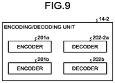
- FIG. 9 is a block diagram illustrating an example of a functional configuration of an encoding/decoding unit 14 - 2 in the second embodiment. Note that a schematic configuration of a memory system according to the second embodiment is similar to the schematic configuration of the memory system in the first embodiment illustrated in FIG. 1 except for the encoding/decoding unit 14 - 2 , and therefore description thereof will be omitted.
- the encoding/decoding unit 14 - 2 includes encoders 201 a and 201 b and decoders 202 - 2 a and 202 b .
- a function of the decoder 202 - 2 a is different from that of the decoder 202 a in the first embodiment.
- Other functions are similar to those in the first embodiment, and therefore the functions are denoted by the same reference signs, and description thereof will be omitted.
- the decoder 202 - 2 a determines SB indexes on the basis of not only a decoding result (HB) and the number of correction bits but also an absolute value ⁇ of an original LLR of the corrected bit. For example, SB1 to SB4 obtained when reading from the nonvolatile memory 20 is performed are stored in an area of the shared memory 17 , the area being different from a storage area for SB1 to SB4 that are updated in repetition decoding, and the decoder 202 - 2 a calculates the original LLR on the basis of the SB1 to SB4 stored in the area and an LLR table (stored on the shared memory 17 , for example). For example, the original LLR may be calculated by using the SB1 to SB4 obtained when reading from the nonvolatile memory 20 is performed, be stored on the shared memory 17 , and be referred to in the decoder 202 - 2 a.
- an LLR obtained after the i-th bit is decoded is expressed by the following expression (11).
- abs(LLR) denotes an absolute value of the LLR.
- LLR ( b i ) log( P ( b i 0
- a probability that correction of a code word corrected with the number of correction bits ⁇ is correct and a probability that the correction is error correction when an error rate (BER) expected in a certain code is ⁇ are obtained in advance by simulation.
- a probability that correction is correct and a probability that the correction is error correction when an expected error rate (BER) is ⁇ and an absolute value of an LLR of a bit corrected with the number of correction bits ⁇ is ⁇ are calculated by simulation.
- the decoder 202 - 2 a determines values of indexes as follows, for example, on the basis of the HB serving as a result of hard decision decoding performed by the decoder 202 - 2 a , the number of correction bits ⁇ performed at the time of the hard decision decoding, and the absolute value ⁇ of the original LLR.
- the decoder 202 - 2 a may determine different indexes for respective combinations of the HB, the number of correction bits t, and a range including the absolute value ⁇ of the original LLR.
- a condition of the range and the number of indexes are not limited to the above-mentioned examples.
- a value indicating a boundary of the range is not limited to “3” and may be another value.
- a condition of a range of 3 or more may be used, such as ⁇ 3, 3 ⁇ 5, and 5 ⁇ .
- twelve indexes for twelve combinations in total may be used on the basis of values of the HB (0 or 1) and the number of correction bits t (1 or 2).
- the value of the LLR may be integrated on the basis of the number of usable indexes. For example, in a case where eight indexes are unused and twelve indexes cannot be allotted, the twelve indexes may be used by being integrated into the above-mentioned eight indexes.
- FIG. 10 is a flowchart illustrating an example of the repetition decoding process in this embodiment.
- Step S 208 is different from Step S 108 in FIG. 8 illustrating the flow of the repetition decoding process in the first embodiment.
- Step S 201 , Step S 202 , Step S 203 , Step S 204 , Step S 205 , Step S 206 , Step S 207 , Step S 209 , Step S 210 , and Step S 211 are similar to Step S 101 , Step S 102 , Step S 103 , Step S 104 , Step S 105 , Step S 106 , Step S 107 , Step S 109 , Step S 110 , and Step S 111 , respectively, in FIG. 8 illustrating the flow of the repetition decoding process in the first embodiment, and therefore description thereof will be omitted.
- Step S 208 the decoder 202 - 2 a determines values of SB indexes (SB1 to SB4) on the basis of an HB serving as a decoding result, the number of correction bits performed by hard decision decoding, and an absolute value of an original LLR of a correction bit (Step S 208 ).
- an SB-index arithmetic unit having a function of determining SB indexes may be included in the shared memory 17 .
- the decoder 202 - 2 a provides the HB serving as the decoding result of the hard decision decoding and correction information (the number of correction bits, a position of a correction bit, and the like) to the SB-index arithmetic unit of the shared memory 17 .
- the SB-index arithmetic unit calculates the original LLR on the basis of an LLR table and original SB1 to SB4.
- the SB-index arithmetic unit determines values of SB indexes (SB1 to SB4) on the basis of the HB and the number of correction bits received from the decoder 202 - 2 a and a calculated absolute value of the original LLR.
- the SB-index arithmetic unit stores the determined values of the SB indexes in a storage area of the shared memory 17 .
- indexes for calculating an LLR are determined in consideration of not only a decoding result and the number of correction bits but also an original LLR of a correction bit. Therefore, it is possible to calculate an LLR accurately, as compared to the first embodiment.
- an incremental Euclidian distance (IED) serving as an index indicating likelihood of decoding is used instead of an absolute value ⁇ of an original LLR used in the second embodiment. That is, in this embodiment, the IED is used as a state of hard decision decoding.
- the IED indicates, for example, a sum of absolute values of original LLRs of all correction bits obtained when a code word Y serving as a decoding result is obtained.
- FIG. 11 is a block diagram illustrating an example of a functional configuration of an encoding/decoding unit 14 - 3 in the third embodiment. Note that a schematic configuration of a memory system according to the third embodiment is similar to the schematic configuration of the memory system in the first embodiment illustrated in FIG. 1 except for the encoding/decoding unit 14 - 3 , and therefore description thereof will be omitted.
- the encoding/decoding unit 14 - 3 includes encoders 201 a and 201 b and decoders 202 - 3 a and 202 b .
- a function of the decoder 202 - 3 a is different from that of the decoder 202 a in the first embodiment.
- Other functions are similar to those in the first embodiment, and therefore the functions are denoted by the same reference signs, and description thereof will be omitted.
- the decoder 202 - 3 a determines SB indexes on the basis of not only a decoding result (HB) but also a value ⁇ of the IED. For example, SB1 to SB4 obtained when reading from the nonvolatile memory 20 is performed are stored in an area of the shared memory 17 , the area being different from a storage area for SB1 to SB4 that are updated in repetition decoding, and the decoder 202 - 3 a calculates the original LLR of each of one or more correction bits on the basis of the SB1 to SB4 stored in the area and an LLR table (stored in the shared memory 17 , for example). Further, the decoder 202 - 3 a calculates a sum of the absolute values of the LLRs calculated for the respective correction bits as the value ⁇ of the IED.
- an LLR obtained after the i-th bit is decoded is expressed by the following expression (12).
- the expression (12) expresses an LLR obtained after each bit is decoded, where an IED (Y IED ) for the decoded code word Y is ⁇ .
- LLR ( b i ) log( P ( b i 0
- Y IED ⁇ )) (12)
- a probability that correction is correct and a probability that correction is error correction when an expected error rate (BER) is ⁇ and a value of the IED is ⁇ are obtained by simulation.
- the decoder 202 - 3 a determines values of indexes as follows, for example, on the basis of the HB serving as a result of hard decision decoding performed by the decoder 202 - 3 a and the value ⁇ of the IED.
- the decoder 202 - 3 a may determine different indexes for respective combinations of the HB and a range including the value ⁇ of the IED.
- a condition of the range and the number of indexes are not limited to the above-mentioned examples.
- the value of the LLR may be integrated on the basis of the number of usable indexes.
- FIG. 12 is a flowchart illustrating an example of the repetition decoding process in this embodiment.
- Step S 308 is different from Step S 108 in FIG. 8 illustrating the flow of the repetition decoding process in the first embodiment.
- Step S 301 , Step S 302 , Step S 303 , Step S 304 , Step S 305 , Step S 306 , Step S 307 , Step S 309 , Step S 310 , and Step S 311 are similar to Step S 101 , Step S 102 , Step S 103 , Step S 104 , Step S 105 , Step S 106 , Step S 107 , Step S 109 , Step S 110 , and Step S 111 , respectively, in FIG. 8 illustrating the flow of the repetition decoding process in the first embodiment, and therefore description thereof will be omitted.
- Step S 309 the decoder 202 - 3 a determines values of SB indexes (SB1 to SB4) on the basis of an HB serving as a decoding result and a value ⁇ of the IED that is a sum of absolute values of original LLRs (Step S 308 ).
- an SB-index arithmetic unit having a function of determining SB indexes may be included in the shared memory 17 .
- the decoder 202 - 3 a provides the HB serving as the decoding result of the hard decision decoding and correction information (the number of correction bits, a position of a correction bit, and the like) to the SB-index arithmetic unit of the shared memory 17 .
- the SB-index arithmetic unit calculates the original LLR of each of one or more corrections bits on the basis of an LLR table and original SB1 to SB4.
- the SB-index arithmetic unit calculates a sum of absolute values of the LLRs calculated for the respective correction bits as the value ⁇ of the IED.
- the SB-index arithmetic unit determines values of SB indexes (SB1 to SB4) on the basis of the HB received from the decoder 202 - 3 a and the calculated value ⁇ of the IED.
- the SB-index arithmetic unit stores the determined values of the SB indexes in a storage area of the shared memory 17 .
- indexes for calculating an LLR are determined in consideration of not only a decoding result but also a sum (IED) of absolute values of original LLRs of correction bits. Therefore, it is possible to calculate an LLR accurately, as compared to the first embodiment.
Landscapes
- Engineering & Computer Science (AREA)
- Theoretical Computer Science (AREA)
- Physics & Mathematics (AREA)
- Probability & Statistics with Applications (AREA)
- Quality & Reliability (AREA)
- General Engineering & Computer Science (AREA)
- General Physics & Mathematics (AREA)
- Computer Hardware Design (AREA)
- Error Detection And Correction (AREA)
- Detection And Correction Of Errors (AREA)
- Techniques For Improving Reliability Of Storages (AREA)
Abstract
Description
LLR(b i)=log(P(
P(b i=0|Y t=α)=P(b i=0, X=Y t=α |Y t=α)+P(b i=0, X≠Y t=α |Y t=α) (2)
P(b i=0|Y t=α ≈P(b i=0, X=Y t=α |Y t=α) (3)
-
- When the i-th bit is corrected from “1” to “0” LLR(bi)=log(P(
b i0|Yt=1)/P(bi=1|Yt=1))=log 9=2.19 - When the i-th bit is corrected from “0” to “1” LLR(bi)=log(P(bi=0|Yt=1)/P(bi=1|Yt=1))=log (1/9)=−2.19
- When the i-th bit is corrected from “1” to “0” LLR(bi)=log(P(
P cor, α=t=N C 1×r C t×βt×(1−β)Nr-t (5)
P mis, α=1 =P mis, α=1, e=3 +P mis, α=1, e=5 +P mis, α=1, e=7+ . . . (6)
P mis, α=2 =P mis, α=2, e=2 +P mis, α=2, e=4 +P mis, α=2, e=6+ . . . (7)
P mis, α=3 =P mis, α=3, e=3 +P mis, α=3, e=5 +P mis, α=3, e=7+ . . . (8)
P mis, α=4 =P mis, α=4, e=4 +P mis, α=4, e=6 +P mis, α=4, e=8+ . . . (9)
-
- HB=“0”, t=1: index IDX1
- HB=“0”, t=2: index IDX2
- HB=“0”, t=3: index IDX3
- HB=“1”, t=1: index IDX4
- HB=“1”, t=2: index IDX5
- HB=“1”, t=3: index IDX6
LLR(b i)=log(P(
-
- HB=“0”, t=1, γ<3: index IDX1
- HB=“0”, t=1, γ≥3: index IDX2
- HB=“0”, t=2, γ<3: index IDX3
- HB=“0”, t=2, γ≥3: index IDX4
- HB=“1”, t=1, γ<3: index IDX5
- HB=“1”, t=1, γ≥3: index IDX6
- HB=“1”, t=2, γ<3: index IDX7
- HB=“1”, t=2, γ≥3: index IDX8
LLR(b i)=log(P(
-
- HB=“0”, IED≤1: index IDX1
- HB=“0”, 1<IED≤3: index IDX2
- HB=“0”, 3<IED≤5: index IDX3
- HB=“0”, 5<IED≤9: index IDX4
- HB=“0”, 9<IED: index IDX5
- HB=“1”, IED≤1: index IDX6
- HB=“1”, 1<IED≤3: index IDX7
- HB=“1”, 3<IED≤5: index IDX8
- HB=“1”, 5<IED≤9: index IDX9
- HB=“1”, 9<IED: index IDX10
Claims (20)
Applications Claiming Priority (2)
| Application Number | Priority Date | Filing Date | Title |
|---|---|---|---|
| JP2019-051045 | 2019-03-19 | ||
| JP2019051045A JP7237674B2 (en) | 2019-03-19 | 2019-03-19 | memory system |
Publications (2)
| Publication Number | Publication Date |
|---|---|
| US20200301777A1 US20200301777A1 (en) | 2020-09-24 |
| US10908994B2 true US10908994B2 (en) | 2021-02-02 |
Family
ID=72515797
Family Applications (1)
| Application Number | Title | Priority Date | Filing Date |
|---|---|---|---|
| US16/541,269 Active US10908994B2 (en) | 2019-03-19 | 2019-08-15 | Memory system and method of controlling nonvolatile memory |
Country Status (2)
| Country | Link |
|---|---|
| US (1) | US10908994B2 (en) |
| JP (1) | JP7237674B2 (en) |
Families Citing this family (5)
| Publication number | Priority date | Publication date | Assignee | Title |
|---|---|---|---|---|
| JP2021044750A (en) * | 2019-09-12 | 2021-03-18 | キオクシア株式会社 | Memory system |
| CN113473460B (en) * | 2021-06-07 | 2022-07-01 | 西安电子科技大学 | Wireless physical layer key negotiation method based on error correcting code judgment |
| JP7614968B2 (en) | 2021-07-19 | 2025-01-16 | キオクシア株式会社 | Semiconductor memory device and system |
| CN113890673B (en) * | 2021-09-01 | 2023-03-14 | 哲库科技(北京)有限公司 | Decoding method, decoding device and storage medium |
| JP7797180B2 (en) * | 2021-11-26 | 2026-01-13 | キオクシア株式会社 | Memory system and non-volatile memory |
Citations (13)
| Publication number | Priority date | Publication date | Assignee | Title |
|---|---|---|---|---|
| US20100058152A1 (en) | 2008-09-04 | 2010-03-04 | Kabushiki Kaisha Toshiba | Decoding apparatus and method |
| JP4599625B2 (en) | 2008-02-20 | 2010-12-15 | 株式会社シンセシス | Error correction decoder |
| US20140208182A1 (en) | 2013-01-21 | 2014-07-24 | Sony Coporation | Controller, information processing system, method of controlling controller, and program |
| US20150169406A1 (en) * | 2013-12-16 | 2015-06-18 | Sandisk Technologies Inc. | Decoding techniques for a data storage device |
| US20160006458A1 (en) * | 2014-07-01 | 2016-01-07 | Sandisk Technologies Inc. | Decoding techniques for low-density parity check codes |
| US20160247576A1 (en) * | 2015-02-23 | 2016-08-25 | SK Hynix Inc. | Memory controller and operating method thereof |
| US20160246673A1 (en) * | 2015-02-23 | 2016-08-25 | SK Hynix Inc. | Controller, semiconductor memory system and operating method thereof |
| US20160266972A1 (en) * | 2015-03-10 | 2016-09-15 | Kabushiki Kaisha Toshiba | Memory controller, storage device and decoding method |
| US20160266968A1 (en) * | 2015-03-09 | 2016-09-15 | Kabushiki Kaisha Toshiba | Memory controller, storage device and decoding method |
| US20170257122A1 (en) * | 2016-03-02 | 2017-09-07 | Kabushiki Kaisha Toshiba | Memory controller and decoding method |
| US9954558B1 (en) * | 2016-03-03 | 2018-04-24 | Avago Technologies General Ip (Singapore) Pte. Ltd. | Fast decoding of data stored in a flash memory |
| US20180341543A1 (en) * | 2017-05-26 | 2018-11-29 | SK Hynix Inc. | Controller, semiconductor memory system and operating method thereof |
| US20190295659A1 (en) * | 2018-03-21 | 2019-09-26 | SK Hynix Inc. | Memory controller and memory system having the same |
Family Cites Families (1)
| Publication number | Priority date | Publication date | Assignee | Title |
|---|---|---|---|---|
| JP6840591B2 (en) | 2017-03-24 | 2021-03-10 | キオクシア株式会社 | Decryptor |
-
2019
- 2019-03-19 JP JP2019051045A patent/JP7237674B2/en active Active
- 2019-08-15 US US16/541,269 patent/US10908994B2/en active Active
Patent Citations (14)
| Publication number | Priority date | Publication date | Assignee | Title |
|---|---|---|---|---|
| JP4599625B2 (en) | 2008-02-20 | 2010-12-15 | 株式会社シンセシス | Error correction decoder |
| US20100058152A1 (en) | 2008-09-04 | 2010-03-04 | Kabushiki Kaisha Toshiba | Decoding apparatus and method |
| US20140208182A1 (en) | 2013-01-21 | 2014-07-24 | Sony Coporation | Controller, information processing system, method of controlling controller, and program |
| JP2014140111A (en) | 2013-01-21 | 2014-07-31 | Sony Corp | Controller, information processing system, method of controlling controller, and program |
| US20150169406A1 (en) * | 2013-12-16 | 2015-06-18 | Sandisk Technologies Inc. | Decoding techniques for a data storage device |
| US20160006458A1 (en) * | 2014-07-01 | 2016-01-07 | Sandisk Technologies Inc. | Decoding techniques for low-density parity check codes |
| US20160247576A1 (en) * | 2015-02-23 | 2016-08-25 | SK Hynix Inc. | Memory controller and operating method thereof |
| US20160246673A1 (en) * | 2015-02-23 | 2016-08-25 | SK Hynix Inc. | Controller, semiconductor memory system and operating method thereof |
| US20160266968A1 (en) * | 2015-03-09 | 2016-09-15 | Kabushiki Kaisha Toshiba | Memory controller, storage device and decoding method |
| US20160266972A1 (en) * | 2015-03-10 | 2016-09-15 | Kabushiki Kaisha Toshiba | Memory controller, storage device and decoding method |
| US20170257122A1 (en) * | 2016-03-02 | 2017-09-07 | Kabushiki Kaisha Toshiba | Memory controller and decoding method |
| US9954558B1 (en) * | 2016-03-03 | 2018-04-24 | Avago Technologies General Ip (Singapore) Pte. Ltd. | Fast decoding of data stored in a flash memory |
| US20180341543A1 (en) * | 2017-05-26 | 2018-11-29 | SK Hynix Inc. | Controller, semiconductor memory system and operating method thereof |
| US20190295659A1 (en) * | 2018-03-21 | 2019-09-26 | SK Hynix Inc. | Memory controller and memory system having the same |
Non-Patent Citations (1)
| Title |
|---|
| S. Jeon, E. Hwang, B. V. K. V. Kumar and M. K. Cheng, "LDPC Codes for Memory Systems with Scrubbing," 2010 IEEE Global Telecommunications Conference GLOBECOM 2010, Miami, FL, 2010, pp. 1-6. (Year: 2010). * |
Also Published As
| Publication number | Publication date |
|---|---|
| US20200301777A1 (en) | 2020-09-24 |
| JP7237674B2 (en) | 2023-03-13 |
| JP2020155861A (en) | 2020-09-24 |
Similar Documents
| Publication | Publication Date | Title |
|---|---|---|
| US10908994B2 (en) | Memory system and method of controlling nonvolatile memory | |
| CN111726121B (en) | Error correction decoder and memory system having the same | |
| US20210211142A1 (en) | Decoding device and decoding method | |
| US10574272B2 (en) | Memory system | |
| US10423484B2 (en) | Memory controller, memory system, and control method | |
| US11025281B2 (en) | Memory system | |
| US20160266972A1 (en) | Memory controller, storage device and decoding method | |
| US10795761B2 (en) | Memory system and method of controlling non-volatile memory | |
| US10467090B2 (en) | Memory controller and decoding method | |
| KR20200033688A (en) | Error correction circuit and operating method thereof | |
| US11150813B2 (en) | Memory system | |
| US11455209B2 (en) | Memory system | |
| KR102314481B1 (en) | Siso decoding method, decoder and semiconductor memory system using the same | |
| US11664822B2 (en) | Multidimensional encoding and decoding in memory system | |
| US11309918B2 (en) | Memory system | |
| KR102226174B1 (en) | Iterative decoder, decoding method and semiconductor memory system | |
| US11204831B2 (en) | Memory system | |
| US20250096816A1 (en) | Memory system and control method | |
| US11886738B2 (en) | Memory system and memory control method | |
| KR102530269B1 (en) | Ldpc decoder, semiconductor memory system and operating method thereof | |
| US12411732B2 (en) | Memory system and control method | |
| US12619362B2 (en) | Memory system and control method | |
| US20250285702A1 (en) | Memory system and method of controlling non-volatile memory | |
| US20240264749A1 (en) | Memory system and control method | |
| US20260056839A1 (en) | Memory system, memory controller, and control method |
Legal Events
| Date | Code | Title | Description |
|---|---|---|---|
| AS | Assignment |
Owner name: TOSHIBA MEMORY CORPORATION, JAPAN Free format text: ASSIGNMENT OF ASSIGNORS INTEREST;ASSIGNORS:KIFUNE, NAOKO;UCHIKAWA, HIRONORI;FUJIKI, TAKAHIRO;AND OTHERS;SIGNING DATES FROM 20190725 TO 20190731;REEL/FRAME:050059/0929 |
|
| FEPP | Fee payment procedure |
Free format text: ENTITY STATUS SET TO UNDISCOUNTED (ORIGINAL EVENT CODE: BIG.); ENTITY STATUS OF PATENT OWNER: LARGE ENTITY |
|
| STPP | Information on status: patent application and granting procedure in general |
Free format text: NOTICE OF ALLOWANCE MAILED -- APPLICATION RECEIVED IN OFFICE OF PUBLICATIONS |
|
| STPP | Information on status: patent application and granting procedure in general |
Free format text: PUBLICATIONS -- ISSUE FEE PAYMENT RECEIVED |
|
| STCF | Information on status: patent grant |
Free format text: PATENTED CASE |
|
| AS | Assignment |
Owner name: KIOXIA CORPORATION, JAPAN Free format text: CHANGE OF NAME AND ADDRESS;ASSIGNOR:TOSHIBA MEMORY CORPORATION;REEL/FRAME:058905/0582 Effective date: 20191001 |
|
| MAFP | Maintenance fee payment |
Free format text: PAYMENT OF MAINTENANCE FEE, 4TH YEAR, LARGE ENTITY (ORIGINAL EVENT CODE: M1551); ENTITY STATUS OF PATENT OWNER: LARGE ENTITY Year of fee payment: 4 |