US10908697B2 - Character editing based on selection of an allocation pattern allocating characters of a character array to a plurality of selectable keys - Google Patents
Character editing based on selection of an allocation pattern allocating characters of a character array to a plurality of selectable keys Download PDFInfo
- Publication number
- US10908697B2 US10908697B2 US15/634,969 US201715634969A US10908697B2 US 10908697 B2 US10908697 B2 US 10908697B2 US 201715634969 A US201715634969 A US 201715634969A US 10908697 B2 US10908697 B2 US 10908697B2
- Authority
- US
- United States
- Prior art keywords
- keys
- key
- character
- smartphone
- touch screen
- Prior art date
- Legal status (The legal status is an assumption and is not a legal conclusion. Google has not performed a legal analysis and makes no representation as to the accuracy of the status listed.)
- Active, expires
Links
Images


Classifications
-
- G—PHYSICS
- G06—COMPUTING; CALCULATING OR COUNTING
- G06F—ELECTRIC DIGITAL DATA PROCESSING
- G06F3/00—Input arrangements for transferring data to be processed into a form capable of being handled by the computer; Output arrangements for transferring data from processing unit to output unit, e.g. interface arrangements
- G06F3/01—Input arrangements or combined input and output arrangements for interaction between user and computer
- G06F3/02—Input arrangements using manually operated switches, e.g. using keyboards or dials
- G06F3/023—Arrangements for converting discrete items of information into a coded form, e.g. arrangements for interpreting keyboard generated codes as alphanumeric codes, operand codes or instruction codes
- G06F3/0233—Character input methods
- G06F3/0236—Character input methods using selection techniques to select from displayed items
-
- G—PHYSICS
- G06—COMPUTING; CALCULATING OR COUNTING
- G06F—ELECTRIC DIGITAL DATA PROCESSING
- G06F3/00—Input arrangements for transferring data to be processed into a form capable of being handled by the computer; Output arrangements for transferring data from processing unit to output unit, e.g. interface arrangements
- G06F3/01—Input arrangements or combined input and output arrangements for interaction between user and computer
- G06F3/018—Input/output arrangements for oriental characters
-
- G—PHYSICS
- G06—COMPUTING; CALCULATING OR COUNTING
- G06F—ELECTRIC DIGITAL DATA PROCESSING
- G06F3/00—Input arrangements for transferring data to be processed into a form capable of being handled by the computer; Output arrangements for transferring data from processing unit to output unit, e.g. interface arrangements
- G06F3/01—Input arrangements or combined input and output arrangements for interaction between user and computer
- G06F3/02—Input arrangements using manually operated switches, e.g. using keyboards or dials
- G06F3/023—Arrangements for converting discrete items of information into a coded form, e.g. arrangements for interpreting keyboard generated codes as alphanumeric codes, operand codes or instruction codes
- G06F3/0233—Character input methods
- G06F3/0235—Character input methods using chord techniques
-
- G—PHYSICS
- G06—COMPUTING; CALCULATING OR COUNTING
- G06F—ELECTRIC DIGITAL DATA PROCESSING
- G06F3/00—Input arrangements for transferring data to be processed into a form capable of being handled by the computer; Output arrangements for transferring data from processing unit to output unit, e.g. interface arrangements
- G06F3/01—Input arrangements or combined input and output arrangements for interaction between user and computer
- G06F3/02—Input arrangements using manually operated switches, e.g. using keyboards or dials
- G06F3/023—Arrangements for converting discrete items of information into a coded form, e.g. arrangements for interpreting keyboard generated codes as alphanumeric codes, operand codes or instruction codes
- G06F3/0233—Character input methods
- G06F3/0237—Character input methods using prediction or retrieval techniques
-
- G—PHYSICS
- G06—COMPUTING; CALCULATING OR COUNTING
- G06F—ELECTRIC DIGITAL DATA PROCESSING
- G06F3/00—Input arrangements for transferring data to be processed into a form capable of being handled by the computer; Output arrangements for transferring data from processing unit to output unit, e.g. interface arrangements
- G06F3/01—Input arrangements or combined input and output arrangements for interaction between user and computer
- G06F3/048—Interaction techniques based on graphical user interfaces [GUI]
- G06F3/0487—Interaction techniques based on graphical user interfaces [GUI] using specific features provided by the input device, e.g. functions controlled by the rotation of a mouse with dual sensing arrangements, or of the nature of the input device, e.g. tap gestures based on pressure sensed by a digitiser
- G06F3/0488—Interaction techniques based on graphical user interfaces [GUI] using specific features provided by the input device, e.g. functions controlled by the rotation of a mouse with dual sensing arrangements, or of the nature of the input device, e.g. tap gestures based on pressure sensed by a digitiser using a touch-screen or digitiser, e.g. input of commands through traced gestures
- G06F3/04886—Interaction techniques based on graphical user interfaces [GUI] using specific features provided by the input device, e.g. functions controlled by the rotation of a mouse with dual sensing arrangements, or of the nature of the input device, e.g. tap gestures based on pressure sensed by a digitiser using a touch-screen or digitiser, e.g. input of commands through traced gestures by partitioning the display area of the touch-screen or the surface of the digitising tablet into independently controllable areas, e.g. virtual keyboards or menus
Definitions
- the present application relates to an electronic device, a control method and a non-transitory storage medium.
- the electronic devices exemplified above leave room for improvement in technologies relating to character editing operations because it is difficult for visually impaired people to move the cursor to the editing position.
- An electronic device, a control method, and a non-transitory storage medium are disclosed.
- an electronic device comprising: a touch screen; a plurality of first keys arranged along a periphery of the touch screen; a storage configured to stores a character array; and at least one controller configured to execute a character editing process according to an operation on the first key by allocating at least one of characters and phrases included in the character array to each of the first keys and accepting, when detecting the operation on one of the first keys, editing the at least one of the characters and the phrases allocated to the first key on which the operation is detected.
- a control method performed by an electronic device including a touch screen, a plurality of first keys arranged along a periphery of the touch screen, and a storage configured to store a character array
- the control method comprising: executing a character editing process according to an operation on the first key by; allocating at least one of characters and phrases included in the character array to each of the first keys; and accepting, when detecting the operation on one of the first keys, editing the at least one of the characters and the phrases allocated to the first key on which the operation is detected.
- a non-transitory storage medium that stores a program for causing, when executed by an electronic device including a touch screen, a plurality of first keys arranged along a periphery of the touch screen, and a storage configured to store a character array, to execute: executing a character editing process according to an operation on the first key by; allocating at least one of characters and phrases included in the character array to each of the first keys; and accepting, when detecting the operation on one of the first keys, editing the at least one of the characters and the phrases allocated to the first key on which the operation is detected.
- FIG. 1 is a perspective view of a smartphone according to an embodiment
- FIG. 2 is a front view of the smartphone
- FIG. 3 is a rear view of the smartphone
- FIG. 4 is a block diagram of the smartphone
- FIG. 5 is a diagram illustrating an exemplary detection configuration in a touch screen
- FIG. 6 is a table representing exemplary first key data
- FIG. 7 is a table representing exemplary second key data
- FIG. 8 is a table representing exemplary first key data
- FIG. 9 is a table representing exemplary second key data
- FIG. 10 is a diagram illustrating an exemplary display screen
- FIG. 11 is a diagram illustrating exemplary document data
- FIG. 12 is a table illustrating allocation of characters or character arrays to first keys
- FIG. 13 is a diagram illustrating an exemplary display screen according to a character editing process
- FIG. 14 is a diagram illustrating an exemplary display screen according to the character editing process
- FIG. 15 is a diagram illustrating an exemplary display screen according to the character editing process
- FIG. 16 is a diagram illustrating an exemplary display screen according to the character editing process
- FIG. 17 is a diagram illustrating an exemplary display screen according to the character editing process
- FIG. 18 is a diagram illustrating an exemplary display screen according to the character editing process
- FIG. 19 is a diagram illustrating an exemplary display screen according to the character editing process
- FIG. 20 is a diagram illustrating an exemplary display screen according to the character editing process
- FIG. 21 is a diagram illustrating an exemplary display screen according to the character editing process
- FIG. 22 is a diagram illustrating an exemplary display screen according to the character editing process
- FIG. 23 is a diagram illustrating an exemplary display screen according to the character editing process
- FIG. 24 is a diagram illustrating an exemplary display screen according to the character editing process
- FIG. 25 is a diagram illustrating an exemplary display screen according to the character editing process
- FIG. 26 is a diagram illustrating an exemplary display screen according to the character editing process
- FIG. 27 is a diagram illustrating another exemplary display screen according to the character editing process.
- FIG. 28 is a flowchart of an exemplary process procedure of control performed by the smartphone.
- FIG. 29 is a flowchart of an exemplary process procedure of the character editing process performed by the smartphone.
- FIG. 30 is a front view of another exemplary electronic device.
- a smartphone will be described as an exemplary electronic device.
- the smartphone 1 includes a housing 20 .
- the housing 20 includes a front face 1 A, a rear face 1 B and side faces 1 C 1 to 1 C 4 .
- the front face 1 A is a front face of the housing 20 .
- the rear face 1 B is a back face of the housing 20 .
- the side faces 1 C 1 to 1 C 4 are side faces connecting the front face 1 A and the back face 1 B.
- the side faces 1 C 1 to 1 C 4 may be generally referred to as side face 1 C without specifying which face.
- the smartphone 1 includes a touch screen display 2 , buttons (keys) 3 A to 3 C, an illuminance sensor 4 , a proximity sensor 5 , a receiver 7 , a microphone 8 and a camera 12 on the front face 1 A.
- the smartphone 1 includes a speaker 11 and a camera 13 on the rear face 1 B.
- the smartphone 1 includes buttons 3 D to 3 F and a connector 14 on the side face 1 C.
- the buttons 3 A to 3 F may be generally referred to as buttons 3 below without specifying which button.
- the touch screen display 2 includes a display 2 A and a touch screen 2 B.
- each of the display 2 A and the touch screen 2 B is approximately rectangle; however, the shape of the display 2 A and the touch screen 2 B is not limited thereto.
- Each of the display 2 A and the touch screen 2 B may have any shape and is, for example, square or circular.
- the display 2 A and the touch screen 2 B are disposed in a layered manner; however, the arrangement of the display 2 A and the touch screen 2 B is not limited thereto.
- the display 2 A and the touch screen 2 B may be arranged side by side or arrange separately. In the example illustrated in FIG.
- the long sides of the display 2 A are along the long sides of the touch screen 2 B and the short sides of the display 2 A are along the short sides of the touch screen 2 B; however, the manner of layering the display 2 A and the touch screen 2 B is not limited thereto.
- the display 2 A and the touch screen 2 B are arranged in a layered manner, for example, at least one side of the display 2 A need not be along any side of the touch screen 2 B.
- the touch screen display 2 is rectangular and the four sides 2 C, 2 D, 2 E and 2 F are adjacent to the side faces 1 C 1 to 1 C 4 of the housing 20 , respectively.
- the side 2 C of the touch screen display 2 is adjacent to the side face 1 C 4 of the housing 20 .
- the side 2 D of the touch screen display 2 is adjacent to the side face 1 C 3 of the housing 20 .
- the display 2 A includes a display device, such as a liquid crystal display (LCD), an organic electro-luminescence display (OELD) or an inorganic electro-luminescence display (IELD).
- a display device such as a liquid crystal display (LCD), an organic electro-luminescence display (OELD) or an inorganic electro-luminescence display (IELD).
- the display 2 A displays, for example, characters, images, symbols, diagrams, etc.
- the touch screen 2 B detects contact of a finger, a pen, or a stylus pen on the touch screen 2 B.
- the touch screen 2 B detects a position in the touch screen 2 B contacted by multiple fingers, a pen or a stylus pen.
- the finger, the pen or the stylus pen that contacts the touch screen 2 B may be referred to as a “contacting object”.
- the detection system of the touch screen 2 B may be any method, such as a capacitance method, a resistance film method, a surface acoustic wave method or a load sensing method. In order to simplify the following descriptions, it is assumed that the user contacts the touch screen 2 B with the fingers to operate the smartphone 1 .
- the smartphone 1 determines the type of gesture based on at least one of a contact that is detected by the touch screen 2 B, a position in which the contact is detected, a change of a position in which the contact is detected, a time interval between detected contacts and the number of times the contact is detected.
- Gestures are operations performed on the touch screen 2 B. Examples of gestures determined by the smartphone 1 include, but are not limited to, touch, long touch, release, swipe, tap, double tap, long tap, drag, flick, pinch-in, pinch-out, etc.
- the smartphone 1 performs operations according to the gestures that are determined via the touch screen 2 B. This realizes intuitive and easy operability to users.
- the operations performed by the smartphone 1 according to the determined gestures may vary depending on the screen that is displayed on the display 2 A.
- “detection of contact by the touch screen 2 B and determination by the smartphone 1 based on the detected contact that the type of a gesture is X” may be referred to as “detection of X by the smartphone” or “detection of X by the controller” below.
- FIG. 4 is a block diagram of the smartphone 1 .
- the smartphone 1 includes the touch screen display 2 , the buttons 3 , the illuminance sensor 4 , the proximity sensor 5 , a communicator 6 , the receiver 7 , the microphone 8 , a storage 9 , a controller 10 , the speaker 11 , the cameras 12 and 13 , the connector 14 , an acceleration sensor 15 , an orientation sensor 16 , a gyroscope 17 , and an atmospheric pressure sensor 19 .
- the touch screen display 2 includes the display 2 A and the touch screen 2 B.
- the display 2 A displays, for example, characters, images, symbols and diagrams.
- the touch screen 2 B detects contact.
- the controller 10 detects a gesture with respect to the smartphone 1 . Specifically, the controller 10 cooperates with the touch screen 2 B to detect operations (gestures) with respect to the touch screen 2 B (the touch screen display 2 ).
- the touch screen 2 B includes multiple first electrodes 2 B 1 and multiple second electrodes 2 B 2 .
- the first electrodes 2 B 1 are electrodes extending along a direction of long sides of the touch screen 2 B.
- the second electrodes 2 B 2 are electrodes extending along a direction of short sides of the touch screen 2 B.
- the first electrodes 2 B 1 and the second electrodes 2 B 2 intersect in a matrix.
- Each of the intersections of the first electrode 2 B 1 and the second electrode 2 B 2 serves as a detection point 60 of the touch screen 2 B.
- the touch screen 2 B contains multiple detention points 60 .
- the smartphone 1 uses the detection points 60 to specify the position/point of contact in which a contacting object contacts the touch screen 2 B.
- the detection points 60 are positioned in a matrix.
- the detection value at the detection point 60 between the electrodes at which capacitive coupling occurs varies.
- the detection values at the detection points 60 around a point 70 contacted by the contacting object is larger than the detection values at other detection points 60 .
- the smartphone 1 is thus able to detect the point 70 contacted by the contacting object with the touch screen 2 B based on the varied detection values at the detection points 60 .
- the buttons 3 are operated by a user of the smartphone 1 .
- the buttons 3 include the buttons 3 A to 3 F.
- the controller 10 cooperates with the buttons 3 to detect operations on the buttons 3 .
- the operation on the buttons 3 includes, for example, click, double click, triple click, push and multi-push; however, the operations are not limited thereto.
- the buttons 3 A to 3 C are, for example, a home button, a back button and a menu button.
- the button 3 D is, for example, a power on/off button of the smartphone 1 .
- the button 3 D may also serve as a sleep/sleep-release button.
- the buttons 3 E and 3 F are, for example, volume buttons.
- the illuminance sensor 4 detects illuminance of light around the smartphone 1 .
- the illuminance includes the intensity, brightness or luminance of the light.
- the illuminance sensor 4 is used to adjust the luminance of the display 2 A.
- the proximity sensor 5 enables contactless detection of the presence of an object in the vicinity.
- the proximity sensor 5 detects the presence of an object based on, for example, a change in the magnetic field or a change in a return time of a reflective wave of ultrasound.
- the proximity sensor 5 detects that the touch screen display 2 is moved to be close to a face.
- the illuminance sensor 4 and the proximity sensor 5 may be configured as a single sensor.
- the illuminance sensor 4 may be used as a proximity sensor.
- the communicator 6 communicates wirelessly.
- the communication systems supported by the communicator 6 are wireless communication standards.
- the wireless communication standards are, for example, communication standards for, for example, 2G, 3G or 4G cellular phones.
- Examples of cellular phone communication standards include, but are not limited to, LTE (Long Term Evolution), W-CDMA (Wideband Code Division Multiple Access), CDMA2000 (Wideband Code Division Multiple Access 2000), PDC (Personal Digital Cellular), GSM (trademark) (Global System for Mobile Communications), PHS (Personal Handy-phone System), etc.
- the wireless communication standards further include, for example, WiMAX (Worldwide Interoperability for Microwave Access), IEEE802.11, Bluetooth (trademark), IrDA (Infrared Data Association) and NFC (Near Field Communication).
- the communicator 6 may support at least one of the communication standards listed above.
- the receiver 7 and the speaker 11 are an exemplary output unit that outputs sound.
- the receiver 7 and the speaker 11 are able to output, as sound, a sound signal that is transmitted from the controller 10 .
- the receiver 7 may be used to output voice of a partner on calling.
- the speaker 11 may be used to output, for example, ringtone and music. Any one of the receiver 7 and the speaker 11 may have both of the functions.
- the microphone 8 is an exemplary input unit that inputs sound.
- the microphone 8 is able to convert, for example, voice of the user into a sound signal and transmit the sound signal to the controller 10 .
- the storage 9 is able to store programs and data.
- the storage 9 may be also used as a work area in which the results of processes performed by the controller 10 are temporarily stored.
- the storage 9 may include a recording medium.
- the recording medium may include any non-transitory storage medium, such as a semiconductor storage medium or a magnetic storage medium.
- the storage 9 may include multiple types of storage media.
- the storage 9 may include a combination of a portable storage medium, such as a memory card, an optical disk or a magneto-optical disk, and a storage-medium read device.
- the storage 9 may include a storage device that is used as a temporary storage area, such as a random access memory (RAM).
- RAM random access memory
- the programs stored in the storage 9 include an application that is executed on the foreground or the background and a control program that supports operations of the application.
- the application for example, displays a screen on the display 2 A and causes the controller 10 to execute a process corresponding to a gesture that is detected via the touch screen 2 B.
- the control program is, for example, an OS.
- the application and the control program may be installed in the storage 9 via wireless communications by the communicator 6 or a non-transitory storage medium.
- the storage 9 stores, for example, a control program 9 A, an input program 9 B, first key data 9 C, second key data 9 D, condition data 9 E and document data 9 F.
- the control program 9 A is able to provide functions relating to various types of control for causing the smartphone 1 to operate.
- the control program 9 A realizes a calling by, for example, controlling the communicator 6 , the receiver 7 and the microphone 8 .
- the functions that are provided by the control program 9 A include a function of performing various types of control to, for example, change the information displayed on the display 2 A according to the gestures that are detected via the touch screen 2 B.
- the functions that are provided by the control program 9 A include a function of detecting movement or stop of the user who has the smartphone 1 by controlling the acceleration sensor 15 and the atmospheric pressure sensor 19 .
- a function that is provided by the control program 9 A may be used in combination with a function that is provided by another program, such as a calculation application or a calling application.
- the input program 9 B is able to provide a function for inputting texts (characters) to the smartphone 1 .
- the input program 9 B displays first keys in a first key area and displays second keys in a second key area to enable character input.
- the specific method of inputting characters will be described later.
- the input program 9 B may include a function enabling the character input by using another input method.
- the input program 9 B is able to provide a function of reading target information.
- the input program 9 B is able to provide a function of editing characters.
- the first key data 9 C contains information on the first keys displayed in the first key area that is set by the input program 9 B.
- the second key data 9 D contains information on the second keys displayed in the second key area that is set by the input program 9 B.
- the second key data 9 D is key data associated with the first key data 9 C.
- FIG. 6 is a table representing the exemplary first key data.
- FIG. 7 is a table representing the exemplary second key data.
- FIGS. 6 and 7 are exemplary data to perform Japanese “kana” input. Display images and possible inputs in the first key data 9 C are allocated to the first keys in the first key area. For example, a display image of “ row” (a row) and a possible input of “ ” (a) are allocated to 1 of the first key. A display image of “ row” (ka row) and a possible input of “ ” (ka) are allocated to “2” of the first key.
- the second key data 9 D stores correspondence of the second keys contained in the second key area with the first keys. Multiple characters that are allocated to the second keys serve as display images and any one of the characters serves as a possible input. For example, for “ row” (a row) of the first key, “ ” (a) is allocated to 1 of the second key, “ ” (i) is allocated to 2 of the second key, “ ” (u) is allocated to 3 of the second key, “ ” (e) is allocated to 4 of the second key, “ ” (o) is allocated to 5 of the second key, and “line break” is allocated to 6 of the second key, where line break and deletion does not show characters to be input but processing executed when characters are input.
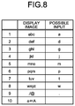
- FIG. 8 is a table representing the exemplary first key data.
- FIG. 9 is a table representing the exemplary second key data.
- FIGS. 8 and 9 are exemplary data for performing alphabet input. Display images and possible inputs in the first key data 9 C are allocated to the first keys contained in the first key area. For example, a display image of “abc” and a possible input of “a” are allocated to 1 of a first key. A display image of “def” and a possible input of “d” are allocated to 2 of the first key.
- the second key data 9 D stores correspondence of the second keys contained in the second key area with the first keys.
- Multiple characters that are allocated to the second keys serve as display images and any one of the characters serves as a possible input. For example, for “abc” of the first key, “a” is allocated to 1 of the second key, “b” is allocated to 2 of the second key, “c” is allocated to 3 of the second key, “A” is allocated to 4 of the second key, “B” is allocated to 5 of the second key, and “C” is allocated to 6 of the second key.
- one character is allocated to one key.
- a character array consisting of two or more characters, such as a word or a sentence, may be allocated to one key. For example, “ ” (arigatou gozaimasu) or “ ” (asu) may be allocated as a possible input to one of the second keys corresponding to “ row” (a row).
- a combination of two or more characters which do not have any meanings may be allocated to one key.
- condition data 9 E various conditions to execute processes by the input program 9 B are set. Specifically, in the condition data 9 E, a correspondence relationship between detected touch gestures and processes to be executed, program conditions, and stop conditions are set.
- the document data 9 F contains information, such as character arrays and characters.
- a character array includes multiple characters. Characters include, for example, kanji characters, hiragana characters, katakana characters, the alphabet and numbers.
- the document data 9 F is created by executing the input program 9 B.
- the document data 9 F is acquired from another electronic device via the communicator 6 .
- the controller 10 includes an arithmetic processing device.
- the arithmetic processing device includes, for example, central processing units (CPU), system-on-a-chips (SoC), micro control units (MCU), field-programmable gate arrays (FPGA) and coprocessors; however, arithmetic processing devices are not limited thereto.
- the controller 10 is able to integrally control operations of the smartphone 1 .
- Various functions of the controller 10 are implemented according to the control by the controller 10 .
- the controller 10 is able to execute commands that are contained in the programs stored in the storage 9 .
- the controller 10 is able to refer to the data stored in the storage 9 when necessary.
- the controller 10 controls a function module according to the data and commands.
- the controller 10 implements various functions by controlling the function module.
- the function module includes, for example, the display 2 A, the communicator 6 , the receiver 7 and the speaker 11 ; however, the function module is not limited thereto.
- the controller 10 may change the control according to a result of detection by a detection module.
- Detection module includes, for example, the touch screen 2 B, the buttons 3 , the illuminance sensor 4 , the proximity sensor 5 , the microphone 8 , the camera 12 , the camera 13 , the acceleration sensor 15 , the orientation sensor 16 , the gyroscope 17 , and the atmospheric pressure sensor 19 ; however, the detection module is not limited thereto.
- the controller 10 is able to execute various types of control to, for example, change the information that is displayed on the display 2 A according to the gesture that is detected via the touch screen 2 B.
- the camera 12 is a front side camera that images an object facing the front face 1 A.
- the camera 13 is a rear side camera that images an object facing the rear face 1 B.
- the connector 14 is a terminal to which another device is connected.
- the connector 14 may be a general-purpose terminal, such as a universal serial bus (USB), a high-definition multimedia interface (HDMI) (trademark), light peak (thunderbolt) (trademark) or an earphone/mic connector.
- the connector 14 may be a dedicated terminal, such as a Dock connector.
- the device connected to the connector 14 includes, for example, external storages, speakers, and communication devices; however, the device is not limited thereto.
- the acceleration sensor 15 is able to detect the direction and magnitude of acceleration act on the smartphone 1 .
- the orientation sensor 16 is able to detect a direction of the earth magnetism.
- the gyroscope 17 is able to detect an angle and an angular velocity of the smartphone 1 .
- the atmospheric pressure sensor 19 is able to detect pressure act on the smartphone 1 . The results of detection by the acceleration sensor 15 , the orientation sensor 16 , the gyroscope 17 and the atmospheric pressure sensor 19 are used in combination to detect changes in a position and an attitude of the smartphone 1 .
- Part or all of the programs and data stored in the storage 9 may be downloaded from another device by wireless communication by the communicator 6 .
- Part or all of the programs and data stored in the storage 9 in FIG. 4 may be stored in a non-transitory storage medium readable by a read device contained in the storage 9 .
- Part or all of the programs and data stored in the storage 9 in FIG. 4 may be stored in a non-transitory storage medium readable by a read device that is connected to the connector 14 .
- the non-transitory storage medium includes, for example, optical disks, such as a CD (trademark), a DVD (trademark) or a Blu-ray (trademark), magneto-optical disks, magnetic storage media, memory cards, and solid-state storage media; however, the non-transitory storage medium is not limited thereto.
- the configuration of the smartphone 1 illustrated in FIG. 4 is an example only. The configuration may be modified within the scope of the application.
- the number of and the type of the buttons 3 are not limited to the example illustrated in FIG. 4 .
- the smartphone 1 may include, instead of the buttons 3 A to 3 C, buttons in the numeric-keypad layout or QWERTY layout as the buttons for screen operation.
- the smartphone 1 may include only one button for screen operation or include no button.
- the smartphone 1 includes two cameras.
- the smartphone 1 may include only one camera or include no camera.
- the smartphone 1 includes four types of sensors in order to detect the position and attitude thereof. The smartphone need not include some of the sensors.
- the smartphone 1 may include another type of sensor to detect at least one of the position and attitude.
- FIG. 10 is a diagram illustrating an exemplary display screen.
- the smartphone 1 displays the screen illustrated in FIG. 10 when executing the character input process by using the input program 9 B.
- the screen illustrated in FIG. 10 includes a first key area 40 , a second key area 42 , a state notifying field 44 , an end key 46 , an input text display field 48 and a determination key 49 .
- Each of the first key area 40 and the second key area 42 contains an area in which multiple software keys are displayed.
- the first key area 40 and the second key area 42 are provided in a position in which the first key area 40 and the second key area 42 overlap the touch screen 2 B.
- the first key area 40 is provided along the side 2 C of the touch screen display 2 and is adjacent to the side 2 C. In other words, the first key area 40 is adjacent to the side face 1 C 4 of the housing 20 .
- multiple first keys 50 a , 50 b , 50 c , 50 d , 50 e , 50 f , 50 g , 50 h , 50 i and 50 j are displayed.
- the first keys 50 a , 50 b , 50 c , 50 d , 50 e , 50 f , 50 g , 50 h , 50 i and 50 j are arranged sequentially along the side 2 C from the top side of the screen to the bottom side.
- Each of the contents of 1 to 10 of the first key data 9 C are allocated to each of the first keys 50 a , 50 b , 50 c , 50 d , 50 e , 50 f , 50 g , 50 h , 50 i and 50 j in the present embodiment. Accordingly, information of 1 of the first key data 9 C is allocated to the first key 50 a and, for “kana” input, an image representing “ row” (a row) is displayed on the first key 50 a.
- the second key area 42 is provided along the side 2 D of the touch screen display 2 and is adjacent to the side 2 D. In other words, the second key area 42 is adjacent to the side face 1 C 3 of the housing 20 .
- the second key area 42 is arranged on a side different from the side of the first key area 40 , i.e., the side facing the side of the first key area 40 in the present embodiment.
- multiple second keys 52 a , 52 b , 52 c , 52 d , 52 e , 52 f , 52 g , 52 h , 52 i and 52 j are displayed.
- the second keys 52 a , 52 b , 52 c , 52 d , 52 e , 52 f , 52 g , 52 h , 52 i and 52 j are sequentially arranged along the side 2 D from the top side of the screen to the bottom side.
- Each of the contents of 1 to 10 of the second key data 9 D are allocated to each of the second keys 52 a , 52 b , 52 c , 52 d , 52 e , 52 f , 52 g , 52 h , 52 i and 52 j according to the present embodiment.
- 1 of the second key data 9 D is allocated to the second key 52 a and, for “kana” input and when “ row” (a row) of the first key 50 a is chosen, an image representing “ ” (a) is displayed on the second key 52 a.
- first keys 50 a , 50 b , 50 c , 50 d , 50 e , 50 f , 50 g , 50 h , 50 i and 50 j will be referred to as first keys 50 when they are not distinguished from one another.
- the second keys 52 a , 52 b , 52 c , 52 d , 52 e , 52 f , 52 g , 52 h , 52 i and 52 j will be referred to as second keys 52 when they are not distinguished from one another.
- the end key 46 is a key to which an ending operation for the text input is allocated.
- the input text display field 48 is a field in which the input character is displayed. In FIG. 10 , an input character array “ ” (arigatou) is displayed. The character array in FIG. 10 is an example only.
- the determination key 49 is a key to which an operation of determining a character that is a possible input as a character to be input is allocated. The determination key 49 is adjacent to both the side 2 C and 2 D. The determination key 49 is adjacent to both the first key area 40 and the second key area 42 . The position in which the determination key 49 is arranged is not limited thereto.
- the smartphone 1 makes a sound output of a character that is a possible input or a character array that is input, i.e., a text/a character array that is displayed on the input text display field 48 in the present embodiment.
- a character that is chosen or a character that is input even in a situation where it is not possible to check the display of the screen.
- the sound output of the character that is a possible input may be made every time when the character that is a possible input changes or alternatively may be made when a rule that is set is satisfied or an operation that is set is executed.
- the images of the first keys 50 and the second keys 52 are displayed on the display 2 A; however, the embodiments are not limited thereto.
- the smartphone 1 it is satisfactory if key inputs are allocated to positions corresponding to the first key area 40 and the second key area 42 in the smartphone 1 , and no image may be displayed. In other words, it is satisfactory if, when the touch screen 2 B detects an input in each area, the input is detected as a key input by allocating each of the first key area 40 , the first keys 50 , the second key area 42 and the second keys 52 to each area in the touchscreen 2 B.
- the electronic device may enable character input in a state where no image is displayed on the display 2 A, or the electronic device need not have the display 2 A. It is preferable that, in a case where no image is displayed, the electronic device makes the above-described sound output when the key operation is detected.
- the case where the contents of the first key data 9 C are allocated to the first keys 50 and the contents of the second key data 9 D are allocated to the second keys 52 in the smartphone 1 has been described; however, the embodiments are not limited thereto.
- the contents of the first key data 9 C may be allocated to the second keys 52 and the contents of the second key data 9 D may be allocated to the first keys 50 .
- the smartphone 1 uses ten keys for the first keys 50 and uses ten keys for the second keys 52 ; however, the embodiments are not limited thereto.
- more than 10 keys or less than 10 keys may be used for the first keys 50 and more than 10 keys or less than 10 keys may be used for the second keys 52 in the smartphone 1 .
- the amount of keys for the first keys 50 may be different from that for the second keys 52 .
- the character editing process includes a process of allocating characters or character arrays to be edited to multiple keys and a process of editing the characters allocated to the keys.
- a case where the character editing process is implemented by executing the input program 9 B will be described; however, the embodiments are not limited thereto.
- the character editing process may be provided as an editing program independently of the input program 9 B.
- FIG. 11 is a diagram illustrating exemplary document data.
- the document data 9 F contains, for example, information representing a document consisting of multiple lines.
- the document contains multiple character arrays.
- the smartphone 1 is able to edit, for example, the document data 9 F that is specified by the user or a character array that are input to the input text display field 48 .
- the document data 9 F contains information representing a Japanese document consisting of nine lines.
- the document data 9 F contains a character array “ ” (mata gojitsu oai dekiru koto wo) as the first line.
- the document data 9 F contains a character array “ ” (kokoromachi ni shite orimasu) as the second line.
- the document data 9 F contains a character array “ ”, (tokorode goshitsumon itadai) as the third line.
- the document data 9 F contains a character array “ ” (teita reino ken desuga, mou) as the fourth line.
- the document data 9 F contains a character array “ ” (sukoshi kaitou ni ojikan itada) as the fifth line.
- the document data 9 F contains a character array “ ” (kemasendeshouka?) as the sixth line.
- the document data 9 F contains a character array “ ” (otesuu okakeshite taihen mou) as the seventh line.
- the document data 9 F contains a character array “ ” (shiwake arimasenga, nanitozo yoro) as the eighth line.
- the document data 9 F contains a character array “ ” (shiku onegai itashimasu) as the ninth line.
- the first to ninth character arrays are linked into one document.
- the smartphone 1 By executing the character editing process of the input program 9 B, the smartphone 1 is able to allocate characters or character arrays to be edited to the first keys 50 or the second keys 52 .
- the smartphone 1 is able to allocate characters or character arrays to be edited to the first keys 50 or the second keys 52 in multiple allocation patterns.
- the multiple allocation patterns include allocation patterns of hiragana character, single character, single word, phrases, single sentence and punctuation marks.
- the hiragana allocation pattern includes an allocation pattern for converting characters or character arrays to be edited into hiragana characters and allocating each hiragana character to the first key 50 or the second key 52 .
- the single character allocation pattern includes an allocation pattern for, regardless of the character type, sequentially allocating characters or character arrays to be edited to the first keys 50 or the second keys 52 .
- the single word allocation pattern includes an allocation pattern for allocating character arrays to be edited to the first keys 50 or the second keys 52 in a minimum unit of language with a meaning and a function grammatically.
- the single line allocation pattern includes an allocation pattern for allocating each line of a document to be edited to the first key 50 or the second key 52 .
- the punctuation mark allocation pattern includes an allocation pattern for allocating character arrays to be edited to the first keys 50 or the second keys 52 in a unit according to punctuation marks.
- FIG. 12 is a table illustrating allocation of characters or character arrays to the first keys 50 .
- the example illustrated in FIG. 12 represents an exemplary case where a user uses the smartphone 1 horizontally.
- the example illustrated in FIG. 12 represents an exemplary case where the document data 9 F illustrated in FIG. 11 is edited.
- the smartphone 1 allocates functions, selective by the user, of backwarding to the previous key group and forwarding to the next key group to the first keys 50 j and 50 a among the ten first keys 50 ; however, the embodiments are not limited thereto.
- the smartphone 1 uses, for example, all the ten first keys 50 as keys to which characters or character arrays are to be allocated.
- a pattern P 1 represents an allocation pattern for “hiragana character”. For example, when the user chooses the hiragana allocation pattern, the smartphone 1 converts kanji characters in the document data 9 F into hiragana characters. For example, the smartphone 1 sequentially allocates the multiple hiragana characters to the first keys 50 i , 50 h , 50 g , 50 f , 50 e , 50 d , 50 c and 50 b , respectively.
- the smartphone 1 is able to sequentially allocate the 9th and the following hiragana characters repeatedly to the first keys 50 i , 50 h , 50 g , 50 f , 50 e , 50 d , 50 c and 50 b , respectively.
- a pattern P 2 represents an allocation pattern for “single character”.
- the smartphone 1 sequentially allocates the multiple characters in the document data 9 F to the first keys 50 i , 50 h , 50 g , 50 f , 50 e , 50 d , 50 c and 50 b , respectively.
- the smartphone 1 is able to sequentially allocate the 9th and the following characters repeatedly to the first keys 50 i , 50 h , 50 g , 50 f , 50 e , 50 d , 50 c and 50 b , respectively.
- a pattern P 3 represents an allocation pattern according to each “word”.
- the smartphone 1 sequentially allocates the multiple words/phrases in the document data 9 F to the first keys 50 i , 50 h , 50 g , 50 f , 50 e , 50 d , 50 c and 50 b , respectively.
- the smartphone 1 is able to sequentially allocate the 9th and the following words/phrases repeatedly to the first keys 50 i , 50 h , 50 g , 50 f , 50 e , 50 d , 50 c and 50 b , respectively.
- the smartphone 1 converts the document data 9 F into hiragana characters and sections the characters into words/phrases; however, the embodiments are not limited thereto.
- the smartphone 1 may, without converting the document data 9 F into hiragana characters, section words/phrases based on the character arrays in which hiragana characters and kanji characters are mixed.
- a pattern 4 represents an allocation pattern according to each “line”.
- the smartphone 1 sequentially allocates the character arrays of the first to eighth lines in the document data 9 F to the first keys 50 i , 50 h , 50 g , 50 f , 50 e , 50 d , 50 c and 50 b , respectively.
- the smartphone 1 is able to sequentially allocate the 9th and the following word arrays repeatedly to the first keys 50 i , 50 h , 50 g , 50 f , 50 e , 50 d , 50 c and 50 b , respectively.
- the smartphone 1 allocates, as the pattern P 1 , the hiragana characters “ ” (ma), “ ” (ta), “ ” (go), “ ” (ji), “ ” (tsu), “ ” (o), “ ” (a) and “ ” (i) to the first keys 50 i , 50 h , 50 g , 50 f , 50 e , 50 d , 50 c and 50 b , respectively.
- the smartphone 1 allocates, as the pattern P 2 , the characters “ ” (ma), “ ” (ta), “ ” (go), “ ” (jitsu), “ ” (o), “ ” (a), “ ” (i) and “ ” (de) in the document data 9 F to the first keys 50 i , 50 h , 50 g , 50 f , 50 e , 50 d , 50 c and 50 b , respectively.
- the smartphone 1 allocates, as the pattern P 3 , the words/phrases “ ” (mata), “ ” (goitsu), “ ” (oai), “ ” (dekiru), “ ” (koto), “ ” (wo) “ ” (kokoromachi) and “ ” (ni) in the document data 9 F to the first keys 50 i , 50 h , 50 g , 50 f , 50 e , 50 d , 50 c and 50 b , respectively.
- the smartphone 1 may section the document containing kanji characters and hiragana characters into words/phrases without converting the kanji characters in the document data 9 F into hiragana characters.
- the smartphone 1 allocates, as the pattern P 4 , the character arrays of the first to eighth lines in the document data 9 F to the first keys 50 i , 50 h , 50 g , 50 f , 50 e , 50 d , 50 c and 50 b , respectively.
- the smartphone 1 displays a horizontal editing screen since the document data 9 F is a horizontal writing; however, the embodiments are not limited thereto.
- the smartphone 1 may display a vertical editing screen even when the document data 9 F is horizontal writing.
- FIGS. 13 to 26 are diagrams illustrating exemplary display screens according to the character editing process.
- the smartphone 1 displays the editing screens illustrated in FIGS. 13 to 26 on the touch screen display 2 .
- Each of the editing screens illustrated in FIGS. 13 to 26 contains the first key area 40 , the second key area 42 , the state notifying field 44 , an editing field 45 , the end key 46 and the determination key 49 .
- the buttons 3 A to 3 C may be used for a fixing operation on the first keys 50 and the second keys 52 .
- the smartphone 1 may use part of the first key area 40 and the second key area 42 for the fixing operation.
- the smartphone 1 may use a key to which no character is allocated in the first key area 40 for the fixing operation.
- the editing field 45 contains a field in which, for example, a document or characters to be edited are displayed.
- the editing field 45 is provided between the first key area 40 and the second key area 42 .
- the second key area 42 is arranged above the editing field 45 and the first key area 40 is arranged below the editing field 45 .
- the first key area 40 is arranged on the right of the editing field 45 and the second key area 42 is arranged on the left of the editing field 45 .
- the smartphone 1 displays the editing screen illustrated in FIG. 13 on the touch screen display 2 .
- the smartphone 1 displays information representing the document in the document data 9 F on the editing field 45 .
- the smartphone 1 displays images which represent types of allocation patterns on the second keys 52 j , 52 i , 52 h , 52 g and 52 f on the editing screen, respectively.
- the smartphone 1 allocates a character deletion function to the second key 52 e and displays the image representing “delete” on the second key 52 e .
- the allocation pattern has not been fixed and thus the smartphone 1 does not allocate characters or character arrays to the first keys 50 .
- the user performs a choosing operation, such as long touch, tap or double tap, on the second key 52 i corresponding to “single character”.
- the choosing operation for example, includes an operation on the determination key 49 or any one of the buttons 3 A to 3 C in a state where the second key 52 i is provisionally chosen.
- the smartphone 1 After detecting the choosing operation on the second key 52 i via the touch screen 2 B, the smartphone 1 changes the second key 52 i on the editing screen to a chosen state. In this case, the smartphone 1 may output sound of, for example, “Reading by single character is set.” from the speaker 11 .
- the smartphone 1 allocates the document data 9 F to the first keys 50 according to the single character allocation pattern corresponding to the chosen second key 52 i.
- the smartphone 1 displays images representing “ ” (ma), “ ” (ta), “ ” (go), “ ” (jitsu), “ ” (o), “ ” (a), “ ” (i) and “ ” (de) in the document data 9 F on the first keys 50 i , 50 h , 50 g , 50 f , 50 e , 50 d , 50 c and 50 b , respectively.
- the smartphone 1 displays images representing “previous” and “next” on the first keys 50 j and 50 a , respectively.
- the smartphone 1 When the first keys 50 j representing “previous” is chosen, the smartphone 1 is able to newly allocate a character group previous to the allocated character group to the first keys 50 i , 50 h , 50 g , 50 f , 50 e , 50 d , 50 c and 50 b .
- the smartphone 1 When the first key 50 a representing “next” is chosen, the smartphone 1 is able to newly allocate a character group next to the allocated character group to the first keys 50 i , 50 h , 50 g , 50 f , 50 e , 50 d , 50 c and 50 b .
- the smartphone 1 need not allocate the functions to the first keys 50 j and 50 a or may make a notification indicating that there is no character group.
- the user performs a provisionally choosing operation on the first key 50 i by, for example, a finger.
- the provisionally choosing operation includes an operation, such as touch.
- the smartphone 1 After detecting the provisionally choosing operation on the first key 50 i via the touch screen 2 B, the smartphone 1 changes the first key 50 i on the screen illustrated in FIG. 15 to a provisionally chosen state.
- the smartphone 1 outputs the sound of “ ” (ma) corresponding to the first key 50 i from the speaker 11 by performing a reading process.
- the reading process includes, for example, a process of converting data to be read into sound.
- the data to be converted into sound includes a character and a character array.
- the smartphone 1 when the user sequentially touches the first keys 50 h and 50 g , the smartphone 1 outputs the sound of “ ” (ta) and “ ” (go) from the speaker 11 .
- a character is a kanji character
- the smartphone 1 is able to read the character and make a sound output of an example using the character for a word.
- the smartphone 1 is able to read as “ , . . . kou of ” (go, . . . kou of kouhan).
- the smartphone 1 when editing characters or character arrays to be edited, the smartphone 1 is able to allocate the characters or character arrays to be edited to the given first keys 50 according to the allocation pattern that is specified by the user.
- the smartphone 1 is able to notify the user of the characters or the character arrays allocated to the first keys 50 by sound.
- the user is able to check the characters to be edited and the sequence of the characters by contacting the first keys 50 arranged along the periphery of the touch screen 2 B and thus is able to find the editing position in the editing field 45 easily.
- the smartphone 1 is able to improve operability for searching for a part that the user wants to edit in the document data 9 F.
- the smartphone 1 is able to reduce possibility that the user takes a wrong part to be edited in the document data 9 F.
- the smartphone 1 changes the first key 50 g to the chosen state after detecting the choosing operation on the first key 50 g via the touch screen 2 B.
- the smartphone 1 accepts editing the chosen character, i.e., enables the editing function.
- the smartphone 1 may display the character “ ” (go) displayed in the editing field 45 and corresponding to the first key 50 g in a display manner different from that of other characters.
- the smartphone 1 displays the character “ ” (go) in a size larger than that of other characters to be enhanced.
- the smartphone 1 may display a cursor on “ ” (go).
- the smartphone 1 allocates display images for performing Japanese “kana” input to the second keys 52 .
- the smartphone 1 displays display images of “ row” (a row), “ row” (ka row), “ row” (sa row), “ row” (ta row), “ row” (na row), “ row” (ha row), “ row” (ma row), “ row” (ya row), “ row” (ra row) and “ row” (wa row) for character input on the second keys 52 j , 52 i , 52 h , 52 g , 52 f , 52 e , 52 d , 52 c , 52 b and 52 a , respectively.
- the smartphone 1 further displays a third key area 47 on the editing screen illustrated in FIG. 17 .
- the third key area 47 includes an area in which multiple software keys are displayed.
- the third key area 47 is provided in a position where the third key area 47 overlaps the touch screen 2 B.
- the third key area 47 is provided along the second key area 42 .
- the third key area 47 is provided along the periphery of the touch screen 2 B.
- multiple third keys 54 a , 54 b , 54 c , 54 d , 54 e and 54 f are displayed.
- the third keys 54 a , 54 b , 54 c , 54 d , 54 e and 54 f of the present embodiment are sequentially arranged from the left of the screen to the right along the second key area 42 .
- the smartphone 1 displays the state notifying field 44 and the third key area 47 between the second key area 42 and the editing field 45 on the editing screen, which reduces the display size of the editing field 45 and thus enables scrolling.
- the third keys 54 a , 54 b , 54 c , 54 d , 54 e and 54 f will be referred to as third keys 54 when they are not distinguished from one another.
- the exemplary smartphone 1 in which the third key area 47 is provided along the second key area 42 will be described; however, the embodiments are not limited thereto.
- the third key area 47 may be provided along the first key area 40 .
- the exemplary smartphone 1 in which the state notifying field 44 and the editing field 45 are provided on the editing screen including the third key area 47 will be described; however, the embodiments are not limited thereto.
- the state notifying field 44 and the editing field 45 need not be provided on the editing screen including the third key area 47 .
- the state notifying field 44 or the editing field 45 may be provided on the editing screen including the third key area 47 .
- the third key area 47 may be provided along the second key area 42 and the first key area 40 .
- the user performs the provisionally choosing operation on the second key 52 j .
- the smartphone 1 After detecting the provisionally choosing operation on the second key 52 j via the touch screen 2 B, the smartphone 1 changes the second key 52 j to the provisionally chosen state.
- the smartphone 1 allocates possible inputs corresponding to “ row” (a row) and a conversion key to the third keys 54 a , 54 b , 54 c , 54 d , 54 e and 54 f .
- row a row
- 54 c a conversion key
- the smartphone 1 displays images representing “ ” (a), “ ” (i), “ ” (u), “ ” (e), “ ” (o), and “convert” on the third keys 54 a , 54 b , 54 c , 54 d , 54 e and 54 f , respectively.
- the user performs the choosing operation on the third key 54 a to which the character “ ” (a) is allocated.
- the smartphone 1 accepts an input of a character corresponding to the third key 54 a and changes the third key 54 a to the chosen state.
- the smartphone 1 displays the chosen character on the state notifying field 44 on the screen.
- the smartphone 1 displays the character “ ” (a) corresponding to the chosen third key 54 a in the state notifying field 44 .
- the user performs the provisionally choosing operation on the second key 52 h to which “ row” (sa row) is allocated and performs the choosing operation on the third key 54 c to which “ ” (su) is allocated.
- the smartphone 1 After detecting the provisionally choosing operation on the second key 52 h via the touch screen 2 B, the smartphone 1 changes the second key 52 h to the provisionally chosen state. In this case, the smartphone 1 allocates possible inputs corresponding to “ row” (sa row) and the conversion key to the third keys 54 a , 54 b , 54 c , 54 d , 54 e and 54 f , respectively.
- the smartphone 1 After detecting the choosing operation on the third key 54 c , the smartphone 1 accepts an input of the character corresponding to the third key 54 c and changes the third key 54 c to the chosen state. In the example illustrated in FIG. 20 , the smartphone 1 additionally displays the character “ ” (su) in the state notifying field 44 . In other words, the smartphone 1 displays the hiragana character array “ ” (asu) in the state notifying field 44 .
- the user performs the choosing operation on the third key 54 f representing “convert” to convert the input characters.
- the smartphone 1 changes the third key 54 f to the chosen state after detecting the choosing operation on the third key 54 f via the touch screen 2 B.
- the smartphone 1 acquires possible conversions of the characters or the character array displayed in the state notifying field 44 .
- the smartphone 1 acquires the possible conversions corresponding to the characters or the character array from, for example, dictionary data or a server.
- the smartphone 1 allocates the possible conversions to the second keys 52 .
- the smartphone 1 displays images of the allocated possible conversions on the second keys 52 .
- the smartphone 1 acquires possible conversions of “ ” (asu), “ ” (asu) and “ ” (asu) as the possible conversions of the characters “ ” (asu).
- the smartphone 1 displays images of “ ” (asu), “ ” (asu) and “ ” (asu) that are the possible conversions on the second keys 52 j , 52 i and 52 h , respectively.
- the smartphone 1 may display the third key area 47 containing the multiple third keys 54 on which no image is displayed on the editing screen illustrated in FIG. 22 .
- the user performs the choosing operation on the second key 52 j representing “ ” (asu).
- the smartphone 1 changes the second key 52 j to the chosen state after detecting the choosing operation on the second key 52 j via the touch screen 2 B.
- the smartphone 1 fixes the editing of the character allocated to the first key 50 g .
- the smartphone 1 fixes the editing of “ ” (go) allocated to the first key 50 g into the characters “ ” (asu).
- the smartphone 1 may display the fixed characters “ ” (asu) in the state notifying field 44 .
- the smartphone 1 reflects the edited characters to the information representing the document displayed in the editing field 45 .
- the smartphone 1 changes “ ” (go) to be edited in the editing field 45 to “ ” (asu) and displays “ ” (asu) in an enhanced manner.
- the smartphone 1 newly allocates the edited “ ” (asu) to the first key 50 g to which “ ” (go) was allocated.
- the smartphone 1 displays images representing “ ” (ma), “ ” (ma), “ ” (asu), “ ” (jitsu), “ ” (o), “ ” (a), “ ” (i) and “ ” (de) in the document data 9 F on the first keys 50 i , 50 h , 50 g , 50 f , 50 e , 50 d , 50 c and 50 b on the editing screen, respectively.
- the smartphone 1 displays multiple images representing the above described allocation pattern types on the second keys 52 j , 52 i , 52 h , 52 g and 52 f on the screen, respectively.
- the smartphone 1 allocates the deletion function in the editing to the second key 52 e and displays the image representing “delete” on the second key 52 e.
- the smartphone 1 after detecting the provisionally choosing operation on any one of the first keys 50 i , 50 h , 50 g , 50 f , 50 e , 50 d , 50 c and 50 b via the touch screen 2 B, the smartphone 1 is able to read a character or a character array allocated to the corresponding first key 50 .
- the smartphone 1 when the user touches the first keys 50 g and 50 f sequentially, the smartphone 1 reads the characters and thus the user is able to recognize that there is the redundant character “ ” (jitsu) followed by “ ” (asu). In order to delete the character of “ ” (jitsu), the user performs a deleting operation on the smartphone 1 .
- the user performs the choosing operation on the second key 52 e representing “delete” in order to delete one character.
- the smartphone 1 determines that deletion of a character or a character array is requested. In this case, the smartphone 1 allocates one character or one character array to be edited to each of the first keys 50 on the editing screen. Accordingly, the smartphone 1 determines that deletion of one character is requested. For example, the smartphone 1 may make a notification indicating that deletion of one character is available by making a sound output.
- the smartphone 1 changes the first key 50 f to the chosen state after detecting the choosing operation on the first key 50 f via the touch screen 2 B.
- the smartphone 1 receives a confirmation for deleting the chosen character from the user and then deletes the character allocated to the first key 50 f .
- the smartphone 1 deletes the character “ ” (jitsu) allocated to the first key 50 f from the document data 9 F.
- the smartphone 1 notifies the user of the deletion of the character by performing the reading process.
- the smartphone 1 makes an output sound of “ , . . . nichi of has been deleted” (jitsu, . . . nichi of nichiyou has been deleted) from the speaker 11 .
- the smartphone 1 deletes the chosen character from the document displayed in the editing field 45 .
- the smartphone 1 re-allocates the characters after the editing to the first keys 50 .
- the smartphone 1 displays images representing “ ” (ma), “ ” (ma), “ ” (a), “ ” (su), “ ” (o), “ ” (a), “ ” (i) and “ ” (de) on the first keys 50 i , 50 h , 50 g , 50 f , 50 e , 50 d , 50 c and 50 b , respectively.
- the smartphone 1 reads the characters and this enables the user to check the edited characters.
- the user is able to confirm that “ ” (gojitsu) in the document displayed in the editing field 45 is changed to “ ” (asu).
- the smartphone when the user performs the choosing operation on the first key 50 to which a character or a character array is allocated, the smartphone is able to edit the character or the character array that is allocated to the first key 50 .
- the smartphone 1 makes it possible to specify a part of the document to be eddited by operating the first keys 50 and change and check the character or the character array of the edited part of the document. Accordingly, for example, it is possible to lower difficulty in editing operations for visually impaired people.
- the smartphone 1 does not change the characters allocated to the first keys 50 except the character to be edited has been described; however the embodiments are not limited thereto.
- the smartphone 1 may re-allocate the characters followed by the edited character and allocated to the first keys 50 at the time when the editing is fixed.
- the smartphone 1 may request the user of the smartphone 1 to re-allocate the characters followed by the edited character and allocated to the first keys 50 .
- the smartphone 1 displays the images representing “ ” (ma), “ ” (ma), “ ” (asu), “ ” (jitsu), “ ” (o), “ ” (a), “ ” (i) and “ ” (de) in the document data 9 F on the first keys 50 i , 50 h , 50 g , 50 f , 50 e , 50 d , 50 c and 50 b on the editing screen, respectively.
- two characters are allocated to the first key 50 g .
- the smartphone 1 when the user wish to allocate the characters after the editing to the first keys 50 one by one, the user performs the choosing operation on the second key 52 i on the editing screen illustrated in FIG. 23 . After detecting the choosing operation on the second key 52 i via the touch screen 2 B, the smartphone 1 changes the second key 52 i on the editing screen to the chosen state. In this case, the smartphone 1 may output sound of, for example, “Reading by single character is set.” from the speaker 11 . By executing the character editing process, the smartphone 1 re-allocates the characters allocated to the first keys 50 after the editing according to the single character allocation pattern corresponding to the chosen second key 52 i.
- FIG. 27 is a diagram illustrating another exemplary display screen according to the character editing process.
- the smartphone 1 displays images representing “ ” (ma), “ ” (ma), “ ” (a), “ ” (su), “ ” (jitsu), “ ” (o), “ ” (a), “ ” (i) after the editing on the first keys 50 i , 50 h , 50 g , 50 f , 50 e , 50 d , 50 c and 50 b , respectively.
- the smartphone 1 when the user sequentially touches the first keys 50 g , 50 f and 50 e , the smartphone 1 reads the characters and thus the user is able to recognize that there is the redundant character “ ” (jitsu) followed by “ ” (a) and “ ” (su). In this case, in order to delete the character “ ” (jitsu), it is satisfactory if the user performs, on the smartphone 1 , an operation of deleting the character “ ” that is allocated to the second key 50 f or the second key 50 e . For example, when the character allocated to the first key is deleted, the smartphone 1 may re-allocate the characters after the editing to the first keys 50 automatically or according to a request from the user.
- FIG. 28 is a flowchart of an exemplary process procedure of control performed by the smartphone 1 .
- the process procedure illustrated in FIG. 28 is implemented by the controller 10 by executing the input program 9 B.
- the process procedure illustrated in FIG. 28 is the process executed in the state where the character editing is requested by the user.
- the controller 10 of the smartphone 1 displays the editing screen on the display 2 A (Step S 101 ). For example, the controller 10 displays the screen illustrated in FIG. 14 on the display 2 A.
- the controller 10 determines whether an operation on the second key 52 is detected via the touch screen 2 B (Step S 102 ). When it is determined that no operation on the second key 52 is detected (NO at Step S 102 ), the controller 10 proceeds to Step S 106 . When it is determined that an operation on the second key 52 is detected (YES at Step S 102 ), the controller 10 proceeds to Step S 103 .
- the controller 10 determines whether it is a provisionally choosing operation on the second key 52 (Step S 103 ). When it is determined that it is a provisionally choosing operation on the second key 52 (YES at Step S 103 ), the controller 10 proceeds to Step S 104 .
- the controller 10 changes the second key 52 on which the provisionally choosing operation is detected to a chosen state (Step S 104 ). For example, the controller 10 displays the second key 52 on the editing screen in a display manner corresponding to the provisionally chosen state. For example, when there is already the second key 52 in the chosen state, the controller 10 is able to releases the chosen state of the second key 52 .
- the controller 10 reads a character or a character array that is allocated to the second key 52 on which the provisionally choosing operation is detected (Step S 105 ). For example, the controller 10 reads the character or the character array that is allocated to the second key 52 by performing the reading process.
- Step S 106 determines whether to end the character editing. For example, when an ending operation for the character editing or a request for ending the character editing is detected, the controller 10 determines to end the character editing. When the controller 10 determines not to end the character editing (NO at Step S 106 ), the controller 10 returns to Step S 102 already described. When the controller 10 determines to end the character editing (YES at Step S 106 ), the controller 10 proceeds to Step S 107 . The controller 10 clears the editing screen on the display 2 A (Step 107 ). After clearing the editing screen, the controller 10 ends the process procedure illustrated in FIG. 28 .
- Step S 108 The controller 10 determines whether it is the choosing operation on the second key 52 (Step S 108 ). When it is determined that it is not the choosing operation on the second key 52 (NO at Step S 108 ), the controller 10 proceeds to Step S 106 already described. When it is determined that it is the choosing operation on the second key 52 (YES at Step S 108 ), the controller 10 proceeds to Step S 109 . The controller 10 executes the character editing process (Step S 109 ). The character editing process will be described later. After ending the character editing process, the controller 10 proceeds to Step S 106 already described.
- FIG. 29 is a flowchart of an exemplary process procedure of the character editing process performed by the smartphone 1 .
- the process procedure illustrated in FIG. 29 is implemented by the controller 10 by executing the input program 9 B.
- the process procedure illustrated in FIG. 29 is the process that is executed at Step S 109 illustrated in FIG. 28 .
- the controller 10 of the smartphone 1 allocates characters to the first keys 50 according to the allocation pattern corresponding to the second key 52 on which the choosing operation is detected (S 201 ). For example, as illustrated in FIG. 14 , the controller 10 allocates the characters in the document data 9 F to the first keys 50 b to 50 i according to the chosen allocation pattern.
- the controller 10 changes the first keys 50 on the editing screen based on the result of allocation to the first keys 50 (S 202 ). For example, the controller 10 displays the images representing the allocated characters on the first keys 50 .
- the controller 10 determines whether an operation on the first key 50 on the editing screen is detected via the touch screen 2 B (S 203 ). When it is determined that no operation on the first key 50 is detected (NO at S 203 ), the controller 10 proceeds to S 207 described later. When it is determined that an operation on the first key 50 is detected (YES at S 203 ), the controller 10 proceeds to S 204 . The controller 10 determines whether it is a provisionally choosing operation on the first key 50 (S 204 ). When it is determined that it is a provisionally choosing operation on the first key 50 (YES at S 204 ), the controller 10 proceeds to S 205 .
- the controller 10 changes the first key 50 on which the provisionally choosing operation is detected to the chosen state (S 205 ). For example, the controller 10 displays the first key 50 on the editing screen in the display manner corresponding to the provisionally chosen state. For example, when there is already the first key 50 in the chosen state, the controller 10 is able to releases the chosen state of the first key 50 .
- the controller 10 reads the character or character array that is allocated to the first key 50 on which the provisionally choosing operation is detected (S 206 ). For example, the controller 10 reads the character or character array allocated to the first key 50 by performing the reading process.
- the controller 10 determines whether to end the character editing process (S 207 ). For example, when an ending operation of the character editing or a request for clearing the editing screen by the user is detected, the controller 10 determines to end the character editing process. When the controller 10 determines not to end the character editing process (NO at S 207 ), the controller 10 returns to S 203 . When the controller 10 determines to end the character editing process (YES at S 207 ), the controller 10 ends the process procedure illustrated in FIG. 29 .
- the controller 10 proceeds to S 208 .
- the controller 10 determines whether it is the choosing operation on the first key 50 (S 208 ). When it is determined that it is not the choosing operation on the first key 50 (NO at S 208 ), the controller 10 proceeds to S 207 already described. When it is determined that it is the choosing operation on the first key 50 (YES at S 208 ), the controller 10 proceeds to Step 209 .
- the controller 10 specifies the character corresponding to the first key 50 on which the choosing operation is detected as the character to be edited (S 209 ).
- the controller 10 executes the character editing process on the specified character (S 210 ).
- the character that is specified as the character to be edited may be a character array.
- the character editing process includes a process of causing the user to edit the character to be edited that is allocated to the first key 50 .
- the character editing process includes a process of causing the user to input a character by using the second key 52 and the third key 54 while maintaining the character allocated to the first key 50 .
- the character editing process includes a process of converting the character that is input by the user.
- the character editing process includes a process of reading the character that is edited by performing the reading process.
- the character editing process includes a process of ending the editing of the character to be edited when a fixing operation of the editing performed by the user is detected.
- the editing process includes a process of causing the user to delete the character allocated to the first key 50 .
- the smartphone 1 allocates the characters or character arrays to be edited to the first keys 50 on the editing screen; however, the embodiments are not limited thereto.
- the smartphone 1 may allocate the characters or character arrays to be edited to the second keys 52 or the third keys 54 .
- the smartphone 1 displays the images of the allocated characters or character arrays on the first keys 50 ; however, the embodiments are not limited thereto.
- the smartphone 1 allocate a key input in a position corresponding to each of the first keys 50 and display no image.
- the smartphone 1 detect the input as a key input and the touch screen 2 B allocate a virtual key to each area.
- the electronic device may enable character editing in a state where no image is displayed on the display 2 A, or the electronic device need not include the display 2 A.
- the electronic device displays no image, it is preferable that a sound output be made when the above-described key operation is detected.
- Each of t programs illustrated in FIG. 4 may be divided into multiple modules or may be combined with another program.
- the smartphone 1 has been described as an exemplary electronic device including the touch screen 2 B; however, the electronic device according to the attached claims is not limited to smartphones.
- the electronic device according to the application may be a portable electronic device other than a smartphone.
- the portable electronic device includes, for example, mobile phones, tablets, portable personal computers, digital cameras, smart watches, media players, electronic book readers, navigators, and game machines; however, the electronic device is not limited thereto.
- FIG. 30 is a front view of another exemplary electronic device.
- An electronic device 101 illustrated in FIG. 30 includes a housing 101 a and a touch screen display 102 whose peripheries are circular.
- a first key area 110 and a second key area 112 are provided in different positions along the peripheries of the housing 101 a and the touch screen display 102 .
- Providing the first key area 110 and the second key area 112 along the peripheries of the housing 101 a and the touch screen display 102 when the peripheries are circular enables easy key input even in a state where the touched area is not checked. According to FIG.
- the electronic device without sides includes the housing 101 a and the touch screen display 102 whose outer shapes (peripheries) are circular; however, the embodiments are not limited thereto.
- the electronic device may include the housing 101 a and the touch screen display 102 whose outer shapes (peripheries) are oval.
- the electronic device may include the housing 101 a and the touch screen display 102 whose outer shapes (peripheries) are polygonal but not rectangular, or are a shape that is a combination of arc and straight line.
Abstract
Description
Claims (15)
Applications Claiming Priority (2)
| Application Number | Priority Date | Filing Date | Title |
|---|---|---|---|
| JP2016-129311 | 2016-06-29 | ||
| JP2016129311A JP6925789B2 (en) | 2016-06-29 | 2016-06-29 | Electronics, control methods, and programs |
Publications (2)
| Publication Number | Publication Date |
|---|---|
| US20180004303A1 US20180004303A1 (en) | 2018-01-04 |
| US10908697B2 true US10908697B2 (en) | 2021-02-02 |
Family
ID=60807531
Family Applications (1)
| Application Number | Title | Priority Date | Filing Date |
|---|---|---|---|
| US15/634,969 Active 2038-02-16 US10908697B2 (en) | 2016-06-29 | 2017-06-27 | Character editing based on selection of an allocation pattern allocating characters of a character array to a plurality of selectable keys |
Country Status (2)
| Country | Link |
|---|---|
| US (1) | US10908697B2 (en) |
| JP (1) | JP6925789B2 (en) |
Families Citing this family (1)
| Publication number | Priority date | Publication date | Assignee | Title |
|---|---|---|---|---|
| JP7357563B2 (en) | 2020-02-05 | 2023-10-06 | シャープ株式会社 | Input editing device and input editing method |
Citations (8)
| Publication number | Priority date | Publication date | Assignee | Title |
|---|---|---|---|---|
| US20110018812A1 (en) * | 2009-07-21 | 2011-01-27 | Cisco Technology, Inc. | Fast Typographical Error Correction for Touchscreen Keyboards |
| US20110035209A1 (en) * | 2009-07-06 | 2011-02-10 | Macfarlane Scott | Entry of text and selections into computing devices |
| JP2012032894A (en) | 2010-07-28 | 2012-02-16 | Kyocera Corp | Electronic apparatus |
| US20120262488A1 (en) | 2009-12-23 | 2012-10-18 | Nokia Corporation | Method and Apparatus for Facilitating Text Editing and Related Computer Program Product and Computer Readable Medium |
| US20120296647A1 (en) * | 2009-11-30 | 2012-11-22 | Kabushiki Kaisha Toshiba | Information processing apparatus |
| US20150161099A1 (en) * | 2013-12-10 | 2015-06-11 | Samsung Electronics Co., Ltd. | Method and apparatus for providing input method editor in electronic device |
| US20170003873A1 (en) * | 2013-07-02 | 2017-01-05 | Realvalue Co., Ltd. | Method for controlling mobile device, recording medium storing program to implement the method, distributing server for distributing application, and mobile device |
| US20170277430A1 (en) * | 2015-03-03 | 2017-09-28 | Omron Corporation | Program for character input system, character input device, and information processing device |
Family Cites Families (1)
| Publication number | Priority date | Publication date | Assignee | Title |
|---|---|---|---|---|
| JP2006148536A (en) * | 2004-11-19 | 2006-06-08 | Sony Corp | Portable terminal, and character inputting method and program |
-
2016
- 2016-06-29 JP JP2016129311A patent/JP6925789B2/en active Active
-
2017
- 2017-06-27 US US15/634,969 patent/US10908697B2/en active Active
Patent Citations (9)
| Publication number | Priority date | Publication date | Assignee | Title |
|---|---|---|---|---|
| US20110035209A1 (en) * | 2009-07-06 | 2011-02-10 | Macfarlane Scott | Entry of text and selections into computing devices |
| US20110018812A1 (en) * | 2009-07-21 | 2011-01-27 | Cisco Technology, Inc. | Fast Typographical Error Correction for Touchscreen Keyboards |
| US20120296647A1 (en) * | 2009-11-30 | 2012-11-22 | Kabushiki Kaisha Toshiba | Information processing apparatus |
| US20120262488A1 (en) | 2009-12-23 | 2012-10-18 | Nokia Corporation | Method and Apparatus for Facilitating Text Editing and Related Computer Program Product and Computer Readable Medium |
| JP2013515984A (en) | 2009-12-23 | 2013-05-09 | ノキア コーポレイション | Method and apparatus for facilitating text editing and associated computer program and computer-readable medium |
| JP2012032894A (en) | 2010-07-28 | 2012-02-16 | Kyocera Corp | Electronic apparatus |
| US20170003873A1 (en) * | 2013-07-02 | 2017-01-05 | Realvalue Co., Ltd. | Method for controlling mobile device, recording medium storing program to implement the method, distributing server for distributing application, and mobile device |
| US20150161099A1 (en) * | 2013-12-10 | 2015-06-11 | Samsung Electronics Co., Ltd. | Method and apparatus for providing input method editor in electronic device |
| US20170277430A1 (en) * | 2015-03-03 | 2017-09-28 | Omron Corporation | Program for character input system, character input device, and information processing device |
Also Published As
| Publication number | Publication date |
|---|---|
| US20180004303A1 (en) | 2018-01-04 |
| JP2018005421A (en) | 2018-01-11 |
| JP6925789B2 (en) | 2021-08-25 |
Similar Documents
| Publication | Publication Date | Title |
|---|---|---|
| US9280275B2 (en) | Device, method, and storage medium storing program | |
| US9086731B2 (en) | Device, method, and storage medium storing program | |
| US7623119B2 (en) | Graphical functions by gestures | |
| US20140139440A1 (en) | Touch operation processing method and device | |
| US10387033B2 (en) | Size reduction and utilization of software keyboards | |
| JP2010079441A (en) | Mobile terminal, software keyboard display method, and software keyboard display program | |
| US10180780B2 (en) | Portable electronic device including touch-sensitive display and method of controlling selection of information | |
| US10572148B2 (en) | Electronic device for displaying keypad and keypad displaying method thereof | |
| US20110319139A1 (en) | Mobile terminal, key display program, and key display method | |
| EP3447626A2 (en) | Display apparatus and control method thereof | |
| US20140223298A1 (en) | Method of editing content and electronic device for implementing the same | |
| JP2014203460A (en) | Method and apparatus for inputting text in electronic device having touchscreen | |
| US9069391B2 (en) | Method and medium for inputting Korean characters using a touch screen | |
| KR102466990B1 (en) | Apparatus and method for displaying a muliple screen in electronic device | |
| KR20140027838A (en) | A mobile apparatus having a function of hand writing using multi-touch and a control method thereof | |
| KR20130015795A (en) | Method and apparatus for inputting character in a touch device | |
| US10908697B2 (en) | Character editing based on selection of an allocation pattern allocating characters of a character array to a plurality of selectable keys | |
| KR20140131070A (en) | Apparatus and method for generating a message in a portable terminal | |
| JP7036862B2 (en) | Electronics, control methods, and programs | |
| KR20140131051A (en) | electro device comprising pressure sensor and method for controlling thereof | |
| US11221757B2 (en) | Electronic device, control method, and program | |
| KR102157078B1 (en) | Method and apparatus for creating electronic documents in the mobile terminal | |
| US11042289B2 (en) | Electronic device, character input control method, and non-transitory storage medium | |
| JP6936892B2 (en) | Electronics, control methods, and programs | |
| US11659077B2 (en) | Mobile terminal and method for controlling the same |
Legal Events
| Date | Code | Title | Description |
|---|---|---|---|
| AS | Assignment |
Owner name: KYOCERA CORPORATION, JAPAN Free format text: ASSIGNMENT OF ASSIGNORS INTEREST;ASSIGNORS:NAGASAKA, YUSHI;FUJISHIRO, MASATO;INAKOSHI, ATSUHISA;AND OTHERS;SIGNING DATES FROM 20170522 TO 20170524;REEL/FRAME:042831/0933 |
|
| STPP | Information on status: patent application and granting procedure in general |
Free format text: DOCKETED NEW CASE - READY FOR EXAMINATION |
|
| STPP | Information on status: patent application and granting procedure in general |
Free format text: NON FINAL ACTION MAILED |
|
| STPP | Information on status: patent application and granting procedure in general |
Free format text: RESPONSE TO NON-FINAL OFFICE ACTION ENTERED AND FORWARDED TO EXAMINER |
|
| STPP | Information on status: patent application and granting procedure in general |
Free format text: FINAL REJECTION MAILED |
|
| STPP | Information on status: patent application and granting procedure in general |
Free format text: RESPONSE AFTER FINAL ACTION FORWARDED TO EXAMINER |
|
| STPP | Information on status: patent application and granting procedure in general |
Free format text: DOCKETED NEW CASE - READY FOR EXAMINATION |
|
| STPP | Information on status: patent application and granting procedure in general |
Free format text: NON FINAL ACTION MAILED |
|
| STPP | Information on status: patent application and granting procedure in general |
Free format text: RESPONSE TO NON-FINAL OFFICE ACTION ENTERED AND FORWARDED TO EXAMINER |
|
| STPP | Information on status: patent application and granting procedure in general |
Free format text: NOTICE OF ALLOWANCE MAILED -- APPLICATION RECEIVED IN OFFICE OF PUBLICATIONS |
|
| STPP | Information on status: patent application and granting procedure in general |
Free format text: PUBLICATIONS -- ISSUE FEE PAYMENT VERIFIED |
|
| STCF | Information on status: patent grant |
Free format text: PATENTED CASE |