US10908367B2 - Optical connector cleaning tool - Google Patents
Optical connector cleaning tool Download PDFInfo
- Publication number
- US10908367B2 US10908367B2 US15/557,949 US201615557949A US10908367B2 US 10908367 B2 US10908367 B2 US 10908367B2 US 201615557949 A US201615557949 A US 201615557949A US 10908367 B2 US10908367 B2 US 10908367B2
- Authority
- US
- United States
- Prior art keywords
- cleaning
- chemical fiber
- optical connector
- lenses
- cleaning cloth
- Prior art date
- Legal status (The legal status is an assumption and is not a legal conclusion. Google has not performed a legal analysis and makes no representation as to the accuracy of the status listed.)
- Active, expires
Links
Images


Classifications
-
- G—PHYSICS
- G02—OPTICS
- G02B—OPTICAL ELEMENTS, SYSTEMS OR APPARATUS
- G02B6/00—Light guides; Structural details of arrangements comprising light guides and other optical elements, e.g. couplings
- G02B6/24—Coupling light guides
- G02B6/36—Mechanical coupling means
- G02B6/38—Mechanical coupling means having fibre to fibre mating means
- G02B6/3807—Dismountable connectors, i.e. comprising plugs
- G02B6/3833—Details of mounting fibres in ferrules; Assembly methods; Manufacture
- G02B6/3866—Devices, tools or methods for cleaning connectors
-
- B08B1/008—
-
- B—PERFORMING OPERATIONS; TRANSPORTING
- B08—CLEANING
- B08B—CLEANING IN GENERAL; PREVENTION OF FOULING IN GENERAL
- B08B1/00—Cleaning by methods involving the use of tools
- B08B1/10—Cleaning by methods involving the use of tools characterised by the type of cleaning tool
- B08B1/14—Wipes; Absorbent members, e.g. swabs or sponges
- B08B1/143—Wipes
-
- B—PERFORMING OPERATIONS; TRANSPORTING
- B08—CLEANING
- B08B—CLEANING IN GENERAL; PREVENTION OF FOULING IN GENERAL
- B08B1/00—Cleaning by methods involving the use of tools
- B08B1/30—Cleaning by methods involving the use of tools by movement of cleaning members over a surface
-
- B08B1/006—
-
- G—PHYSICS
- G02—OPTICS
- G02B—OPTICAL ELEMENTS, SYSTEMS OR APPARATUS
- G02B6/00—Light guides; Structural details of arrangements comprising light guides and other optical elements, e.g. couplings
- G02B6/24—Coupling light guides
- G02B6/36—Mechanical coupling means
- G02B6/38—Mechanical coupling means having fibre to fibre mating means
- G02B6/3807—Dismountable connectors, i.e. comprising plugs
- G02B6/3873—Connectors using guide surfaces for aligning ferrule ends, e.g. tubes, sleeves, V-grooves, rods, pins, balls
- G02B6/3885—Multicore or multichannel optical connectors, i.e. one single ferrule containing more than one fibre, e.g. ribbon type
Definitions
- the present invention relates to an optical connector cleaning tool that cleans a plurality of lens surfaces of an optical connector by a cleaning cloth.
- the ferrule with lenses of this type is used for an optical port of a transmission apparatus or a plug of an optical cable that connects transmission apparatuses.
- the optical port is formed by a receptacle provided on a transmission apparatus, and is of a so-called female type.
- the plug is provided at the distal end of an optical cable, and is of a so-called male type.
- the mainstream of the ferrule with lenses has a plurality of plastic lenses that are integrally molded, and is stored in the above-described receptacle or plug.
- a plurality of lenses of an optical connector are provided while being arranged on the same plane, and are used in a cleaned state to suppress a loss as much as possible.
- Cleaning of the optical connector can be done by an optical connector cleaning tool as described in, for example, patent literature 2.
- the cleaning tool disclosed in patent literature 2 has a structure in which a cleaning cloth contacts the cleaning target portion of an optical connector, and in this state, moves with respect to the cleaning target portion.
- Patent Literature 1 US 20120093462
- Patent Literature 2 WO 2014/141405
- the conventional optical connector cleaning tool disclosed in patent literature 2 cannot properly clean the uneven lens portion of the ferrule with lenses.
- the cleaning cloth of the cleaning tool is forcibly pressed against the lenses, the lenses made of a plastic are readily damaged.
- the present invention has been made to solve the above-described problem, and has as its object to provide an optical connector cleaning tool capable of cleaning the cleaning target portion of a ferrule with lenses properly without any damage.
- an optical connector cleaning tool including a cleaning head that faces a cleaning target portion of an optical connector, and a cleaning cloth that moves with respect to the cleaning head in a state in which the cleaning cloth is in contact with the cleaning target portion, wherein the cleaning cloth is formed into a strip shape by a fabric including a plurality of warps in which a longitudinal direction thereof is a moving direction of the cleaning cloth moving with respect to the cleaning head, the warp includes a first chemical fiber and a second chemical fiber, and one chemical fiber of the first chemical fiber and the second chemical fiber is in a stretched state, and the other chemical fiber is in a slack state.
- a tensile force acts on the cleaning cloth used to clean the optical connector because the cleaning cloth contacts the cleaning target portion of the optical connector while being wound up at the time of cleaning. If the cleaning cloth is made of one type of chemical fiber, the whole cleaning cloth stretches as the tensile force acts in the cleaning. The uneven lens-shaped cleaning target portion cannot properly be cleaned by the cleaning cloth in the stretched state.
- the wind-up tensile force at the time of cleaning acts on the chemical fiber in a state in which the warps are stretched.
- the chemical fiber in the stretched state resists the wind-up tensile force at the time of cleaning, and the chemical fiber in the slack state is not stretched by the wind-up tensile force.
- the chemical fiber in the slack state enters the valley portions of the unevenness, and the whole region of the cleaning target portion can properly be cleaned.
- the cleaning cloth since the cleaning cloth has slack portions on the warps, the surface of the cleaning cloth softly swells. Hence, the cleaning cloth never damages the cleaning target portion.
- the optical connector cleaning tool can wipe and clean the whole region of the lenses by the cleaning cloth without damaging the lenses.
- a weft formed by a fiber having a relatively small shrinkage factor can be used as the weft that forms the fabric in cooperation of the warps of the cleaning cloth.
- the width of the cleaning cloth is stable. For this reason, even if the cleaning target portion includes a plurality of lenses arranged in the widthwise direction, the cleaning cloth can clean the lenses without extending off the lenses.
- FIG. 1 is a perspective view showing a state in which the cap of an optical connector cleaning tool according to the present invention is attached;
- FIG. 2 is a perspective view showing a state in which the cap of the optical connector cleaning tool is detached;
- FIG. 3 is a side view showing the arrangement in a case
- FIG. 4A is a perspective view showing a state in which a receptacle faces a cleaning head so as to explain a procedure of cleaning a ferrule with lenses in the receptacle;
- FIG. 4B is a perspective view showing a state in which the receptacle is fitted in the cleaning head so as to explain a procedure of cleaning the ferrule with lenses in the receptacle;
- FIG. 4C is a perspective view showing a state in which the cleaning head is pushed into the case so as to explain a procedure of cleaning the ferrule with lenses in the receptacle;
- FIG. 5A is a perspective view showing a state in which an optical plug faces the cap so as to explain a procedure of cleaning an optical connector in the optical plug;
- FIG. 5B is a perspective view showing a state in which the optical plug is fitted in the cap so as to explain a procedure of cleaning the optical connector in the optical plug;
- FIG. 5C is a perspective view showing a state in which the optical plug is in contact with the cleaning head so as to explain a procedure of cleaning the optical connector in the optical plug, in which the cap is not illustrated;
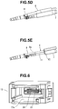
- FIG. 5D is a perspective view showing a state in which the cleaning head is pushed into the case so as to explain a procedure of cleaning the optical connector in the optical plug;
- FIG. 5E is a perspective view showing a state in which the cleaning head is pushed into the case so as to explain a procedure of cleaning the optical connector in the optical plug, in which the cap is not illustrated;
- FIG. 6 is a perspective view showing the receptacle and the ferrule with lenses
- FIG. 7 is a perspective view showing the optical plug and the ferrule with lenses
- FIG. 8 is a perspective view of the ferrule with lenses
- FIG. 9 is a sectional view of the distal end of the cleaning head
- FIG. 10 is a sectional view of the distal end of the cleaning head
- FIG. 11 is a schematic view showing the structure of a fabric serving as a cleaning cloth
- FIG. 12 is a schematic view showing the arrangement of warps and a weft
- FIG. 13 is a micrograph showing the sectional shape of first thread materials before a chemical treatment
- FIG. 14 is a micrograph showing the sectional shape of the first thread materials after the chemical treatment
- FIG. 15 is a micrograph showing the surface shape of the cleaning cloth
- FIG. 16 is an enlarged sectional view showing the contact portion between the cleaning cloth and lenses
- FIG. 17 is a sectional view of the cap in which the cleaning head and the optical plug are fitted;
- FIG. 18 is a schematic view showing the structure of a fabric serving as a cleaning cloth.
- FIG. 19 is a schematic view showing the structure of a fabric serving as a cleaning cloth.
- FIGS. 1 to 19 An optical connector cleaning tool according to an embodiment of the present invention will now be described in detail with reference to FIGS. 1 to 19 .
- An optical connector cleaning tool 1 shown in FIG. 1 employs an arrangement in which a case 2 to be gripped by an operator (not shown) by a hand supports components to be described later.
- the optical connector cleaning tool 1 is different from the optical connector cleaning tool described in patent literature 2 previously proposed by the present applicant only in a cleaning cloth 3 (see FIG. 9 ), a pressing member 16 (see FIG. 9 ), and a cap 8 (see FIG. 1 ) to be described later, and the rest of the arrangement is the same.
- a cleaning head 4 see FIG. 3
- the case 2 of the optical connector cleaning tool 1 includes a grip portion 6 to be gripped by the operator, and a nose portion 7 projecting from the grip portion 6 .
- a description will be made below by defining the direction in which the nose portion 7 projects from the grip portion 6 as frontward or front side, and the opposite direction as rearward or rear side.
- the cap 8 is attached to the nose portion 7 of the case 2 shown in FIG. 1 .
- the cap 8 is used to connect an optical plug 9 (see FIG. 5A ) to be described later.
- the cap 8 is formed into a rectangular tubular shape and detachably attached to the nose portion 7 , as will be described later in detail.
- a cover 8 a that opens/closes an opening portion is pivotally provided at the front end of the cap 8 .
- the cleaning head 4 is formed by two functional units to be described later. As shown in FIG. 3 , the cleaning head 4 is inserted into the whole area in the nose portion 7 and supported by the nose portion 7 to be movable in the front-and-rear direction.
- the two functional units are a cleaning unit 4 a projecting from the nose portion 7 , and a connecting portion 4 b that connects the cleaning unit 4 a to the driving mechanism 5 to be described later.
- the cleaning unit 4 a of the cleaning head 4 is formed by a first rectangular tube 11 that forms the front end, and a second rectangular tube 12 provided on the rear side of the first rectangular tube 11 .
- the second rectangular tube 12 is formed into such a shape that has an opening portion wider and higher than the first rectangular tube 11 .
- a receptacle 13 for an optical port (not shown) or the optical plug 9 for an optical cable is connected to the first rectangular tube 11 .
- the receptacle 13 has a recessed portion 13 a .
- the recessed portion 13 a is formed into a shape in which the optical plug 9 can be fitted.
- the first rectangular tube 11 (see FIGS. 4A to 4C ) of the cleaning head 4 is formed into a shape that is fitted in the recessed portion 13 a .
- the aspect ratio of the opening portion of the first rectangular tube 11 is not 1:1. For this reason, the first rectangular tube 11 is not fitted in the recessed portion 13 a in a wrong orientation.
- a ferrule 14 with lenses (to be described later) that forms “an optical connector” in the present invention is provided on the bottom of the recessed portion 13 a.
- the optical plug 9 includes a connecting portion 9 a having a rectangular tubular shape.
- the front end of the cap 8 is formed into a shape in which the connecting portion 9 a is fitted.
- the ferrule 14 with lenses is provided in the connecting portion 9 a.
- the ferrule 14 with lenses includes a number of lenses 15 .
- the lenses 15 are provided at one end of the ferrule 14 with lenses in a state in which the lenses project from the bottom of a concave portion 14 a formed at the one end.
- the lenses 15 are so-called convex lenses, and are arranged at a predetermined interval in the vertical and horizontal directions that are orthogonal to each other when viewed from the connecting direction.
- the vertical direction in which the lenses 15 are arranged is defined as a Y direction indicated by an arrow
- the horizontal direction is defined as an X direction indicated by an arrow.
- the lenses 15 correspond to “a cleaning target portion of an optical connector” in the present invention.
- part of the strip-shaped cleaning cloth 3 (to be described later) and the pressing member 16 that presses the cleaning cloth 3 to the front side are stored in the first rectangular tube 11 and the second rectangular tube 12 .
- the cleaning cloth 3 is stored in a state in which the cleaning cloth 3 sandwiches the pressing member 16 and extends in the front-and-rear direction along the first rectangular tube 11 and the second rectangular tube 12 .
- the cleaning cloth 3 is folded back along the front end of the pressing member 16 .
- a front end 3 a of the cleaning cloth 3 along the front end of the pressing member 16 cleans the lenses 15 .
- the pressing member 16 is made of a plastic and supported by a front end member 17 of the connecting portion 4 b to be movable in the front-and-rear direction only by a predetermined distance.
- the pressing member 16 is biased frontward by the spring force of a first compression coil spring 18 . For this reason, when the lenses 15 are pressed against the front end 3 a of the cleaning cloth 3 , the pressing member 16 and the cleaning cloth 3 retreat against the spring force of the first compression coil spring 18 , and the cleaning cloth 3 is pressed against the lenses 15 by the spring force of the first compression coil spring 18 .
- the connecting portion 4 b of the cleaning head 4 is formed into a shape extending in the front-and-rear direction in the nose portion 7 , and is biased frontward by a second compression coil spring 19 .
- the connecting portion 4 b is inserted into the central portion of the second compression coil spring 19 , and in this state, the second compression coil spring 19 is compressed and inserted between a pressure receiving piece 4 c provided at the intermediate portion of the connecting portion 4 b and a pressure receiving piece 2 a of the case 2 . For this reason, the cleaning head 4 can move rearward with respect to the case 2 against the spring force of the second compression coil spring 19 .
- the cleaning cloth 3 is passed between the connecting portion 4 b and the nose portion 7 of the case 2 .
- the distal end side of the cleaning cloth 3 is wound around a wind-up reel 21 provided in the grip portion 6 of the case 2 .
- the rear end side of the cleaning cloth 3 is wound around a supply reel 22 provided in the grip portion 6 .
- the wind-up reel 21 and the supply reel 22 are rotatably supported by the case 2 .
- the wind-up reel 21 is driven by the driving mechanism 5 to be described later, and thus rotates clockwise in FIG. 3 and winds up the cleaning cloth 3 .
- the cleaning cloth 3 is pulled and drawn from the supply reel 22 .
- the cleaning cloth 3 moves from the supply reel 22 through the grip portion 6 and the nose portion 7 of the case 2 , the first rectangular tube 11 , and the second rectangular tube 12 .
- the ferrule 14 with lenses is pressed against the cleaning head 4 , the cleaning cloth 3 moves with respect to the lenses 15 and the cleaning head 4 in a state in which the cleaning cloth 3 is contact with the lenses 15 .
- the driving mechanism 5 includes a rack 23 connected to the connecting portion 4 b of the cleaning head 4 , and a gear 24 provided in the wind-up reel 21 in a state in which the gear 24 meshes with the rack 23 .
- the rack 23 rotates the gear 24 and the wind-up reel 21 clockwise in FIG. 3 , and the cleaning cloth 3 is wound up by the wind-up reel 21 . That is, the driving mechanism 5 performs driving so as to pull the cleaning cloth 3 and draws it from the supply reel 22 such that the cleaning cloth 3 moves with respect to the cleaning head 4 .
- the longitudinal direction of the cleaning cloth 3 is inevitably a direction that continues long, that is, a direction in which warps (first thread materials 28 to be described later) shown in FIG. 12 extend.
- the cleaning cloth 3 is formed into a strip shape by a fabric 25 .
- the fabric 25 according to this embodiment is a twill.
- the fabric 25 is formed by a number of warps 26 whose longitudinal direction is the moving direction of the cleaning cloth 3 moving with respect to the cleaning head 4 , and a weft 27 interwoven with the warps 26 .
- the twill is woven with a large float, and the cross points between the warps 26 and the weft 27 are arranged at a predetermined interval.
- the twill can form a soft and thick fabric next to a satin weave.
- One warp 26 of the fabric 25 is formed by bundling a predetermined number of first thread materials 28 shown in FIG. 12 .
- the first thread material 28 shown in FIG. 12 is formed by a first chemical fiber 31 and a second chemical fiber 32 , which extend in the longitudinal direction of the cleaning cloth 3 .
- the first chemical fiber 31 and the second chemical fiber 32 have different shapes, as shown in FIG. 12 .
- the first chemical fiber 31 is in a stretched state and extends straight.
- the second chemical fiber 32 is in a slack state and meanders along the first chemical fiber 31 .
- the first chemical fiber 31 and the second chemical fiber 32 which have the above-described shapes can be implemented by, for example, a chemical treatment using a drug solution.
- the first chemical fiber 31 and the second chemical fiber 32 are considered to be made using materials whose shrinkage factors when dipped in the drug solution are different. That is, the first chemical fiber 31 is made using a material having a relatively large shrinkage factor, and the second chemical fiber 32 is made using a material having a relatively small shrinkage factor.
- the first chemical fiber 31 is made of nylon
- the second chemical fiber 32 is made of PET (polyethylene terephthalate) whose shrinkage factor is smaller than the nylon.
- the first and second chemical fibers are dipped in a drug solution that shrinks nylon.
- the drug solution used in this embodiment has a shrinkage factor of about 20% for nylon.
- the shrinkage factor of the first chemical fiber 31 dipped in the drug solution by the chemical treatment is larger than the shrinkage factor of the second chemical fiber 32 dipped in the drug solution. That is, of the first chemical fiber 31 and the second chemical fiber 32 , the first chemical fiber 31 whose shrinkage factor by the chemical treatment is larger stretches, and the second chemical fiber 32 slackens.
- the shapes shown in FIG. 12 are obtained.
- the first chemical fiber 31 corresponds to “one chemical fiber having a large shrinkage factor” in the present invention.
- the first thread material 28 according to this embodiment is formed by the first chemical fibers 31 in a volume ratio of 60% and the second chemical fibers 32 in a volume ratio of 40%.
- FIG. 13 is a micrograph of the first thread materials 28 before the chemical treatment.
- FIG. 14 is a micrograph of the first thread materials 28 after the chemical treatment.
- the first chemical fibers 31 and the second chemical fibers 32 are spread out by the chemical treatment, and the first chemical fibers 31 shrink largely relative to the second chemical fibers.
- the first thread material 28 shown in FIGS. 13 and 14 is formed using the first chemical fiber 31 as the core.
- the first chemical fiber 31 includes a plurality of plate-shaped pieces 31 a that radially extend in the sectional shape.
- the plate-shaped pieces 31 a are connected to each other at the center of the radiating shape.
- the second chemical fibers 32 each having a triangular sectional shape are arranged between the plurality of plate-shaped pieces 31 a . That is, the second chemical fibers 32 are arranged to surround the first chemical fiber 31 .
- the weft 27 of the fabric 25 includes a second thread material 33 (see FIG. 12 ) made of a chemical fiber that shrinks less than the first chemical fiber 31 (one chemical fiber having a large shrinkage factor) when dipped in the above-described drug solution, and is formed by bundling a plurality of second thread materials 33 .
- the weft 27 is folded back at the two ends of the cleaning cloth 3 in the widthwise direction. That is, at the two ends of the cleaning cloth 3 in the widthwise direction, the warps 26 are gripped by folded portions 27 a of the weft 27 .
- the chemical fiber of the second thread material 33 according to this embodiment is made of PET.
- the slack of the second chemical fibers 32 in contact with the weft 27 (second thread material 33 ) is regulated by the weft 27 .
- slack portions 32 a are formed at portions where the slack is not regulated by the weft 27 in the longitudinal direction of the second chemical fiber 32 . That is, the slack portions 32 a project from the first thread material 28 .
- the recessed portion 13 a of the receptacle 13 is made to oppose the cleaning head 4 , as shown in FIG. 4A .
- the first rectangular tube 11 of the cleaning head 4 is fitted in the recessed portion 13 a . Since the aspect ratios of the recessed portion 13 a and the opening portion of the first rectangular tube 11 are not 1:1, the receptacle 13 is not attached to the first rectangular tube 11 in a wrong orientation. That is, the widthwise direction of the cleaning cloth 3 is parallel to the widthwise direction (X direction) of the plurality of lenses 15 .
- the receptacle 13 After the receptacle 13 is fitted on the first rectangular tube 11 , the receptacle 13 is moved rearward until its distal end face abuts against the front end face of the second rectangular tube 12 .
- the cleaning cloth 3 is brought into contact with the number of lenses 15 of the ferrule 14 with lenses and pressed against the number of lenses 15 by the spring force of the first compression coil spring 18 , as shown in FIG. 16 .
- the tensile force acting on the cleaning cloth 3 is received by the first chemical fibers 31 but is hardly transmitted to the second chemical fibers 32 .
- the slack portions 32 a of the second chemical fibers 32 are not stretched by the tensile force, and are maintained in the initial state, that is, in the state in which the cleaning cloth 3 softly swells.
- the cleaning cloth 3 When the cleaning cloth 3 is pressed against the lenses 15 of the lens-type connector, the slackened second chemical fibers 32 of the cleaning cloth 3 enter the concave portions between the plurality of lenses 15 (convex portions), and the cleaning cloth 3 comes into contact with the whole region of all lenses 15 while conforming to the unevenness made by the plurality of lenses 15 .
- the optical connector cleaning tool 1 is pushed toward the receptacle 13 , and the cleaning head 4 is pushed into the case 2 against the spring force of the second compression coil spring 19 , as shown in FIG. 4C .
- the cleaning head 4 thus moves with respect to the case 2 , the cleaning cloth 3 is wound up by the wind-up reel 21 and moved with respect to the lenses 15 so as to wipe and clean the whole surface region of all lenses 15 .
- the optical connector cleaning tool 1 can wipe and clean the whole region of the lenses 15 by the cleaning cloth 3 .
- the cap 8 is attached to the nose portion 7 , as shown in FIG. 5A .
- the cover 8 a of the cap 8 is not illustrated in FIGS. 5A to 5E .
- the cap 8 is formed into a rectangular tubular shape.
- a first hole 41 in which the nose portion 7 is detachably fitted is formed at one end, that is, the rear end of the cap 8 , as shown in FIG. 17 .
- a second hole 42 in which the connecting portion 9 a of the optical plug 9 is detachably fitted is formed at the other end, that is, the front end of the cap 8 .
- the optical plug 9 is fitted in the second hole 42 of the cap 8 , as shown in FIG. 5B .
- the aspect ratios of the opening of the first hole 41 and the opening of the second hole 42 are not 1:1. For this reason, when attaching the cap 8 to the nose portion 7 and when attaching the optical plug 9 to the cap 8 , they are not attached in a wrong orientation. That is, the widthwise direction of the cleaning cloth 3 is parallel to the widthwise direction (X direction) of the plurality of lenses 15 .
- the optical plug 9 is moved until the first rectangular tube 11 abuts against the ferrule 14 with lenses in the optical plug 9 , as shown in FIG. 5C .
- the cap 8 is not illustrated in FIG. 5C .
- the ferrule 14 with lenses abuts against the first rectangular tube 11 , the cleaning cloth 3 is pressed against the plurality of lenses 15 by the spring force of the first compression coil spring 18 .
- the optical connector cleaning tool 1 is pushed toward the optical plug 9 , and the cleaning head 4 is pushed into the case 2 against the spring force of the second compression coil spring 19 , as shown in FIGS. 5D and 5E .
- the cap 8 is not illustrated in FIG. 5E .
- the optical plug 9 moves in a state in which it is fitted in the second hole 42 of the cap 8 . That is, the second hole 42 forms a guide 43 (see FIG. 17 ) of the optical plug 9 (ferrule 14 with lenses) that moves with respect to the case 2 together with the cleaning head 4 .
- the cleaning cloth 3 is wound up by the wind-up reel 21 and moved with respect to the lenses 15 so as to wipe and clean the whole surface region of all lenses 15 .
- the slack portions 32 a of the warps 26 of the cleaning cloth 3 are inserted into the concave portions between the convex portions of the cleaning target portion. It is therefore possible to clean the whole region of the uneven portions of the cleaning target portion by the slack portions 32 a and other portions of the cleaning cloth 3 .
- the cleaning cloth 3 since the cleaning cloth 3 has the slack portions 32 a on the warps 26 , the surface of the cleaning cloth 3 softly swells. Hence, the cleaning cloth 3 never damages the cleaning target portion. Even if the cleaning target portion includes the plurality of lenses 15 of the ferrule 14 with lenses, the optical connector cleaning tool 1 can wipe and clean the whole region of the lenses 15 by the cleaning cloth 3 without damaging the lenses 15 .
- the fitting length between the two members that is, the rectangular tube 11 and the receptacle 13 is long, and the clearance between the two members is small, the cleaning unit is pressed against the ferrule 14 with lenses at a high perpendicularity, and the cleaning is more reliably performed. More specifically, the fitting length between the rectangular tube 11 and the receptacle is about 20 mm, and the clearance between the two members is 1 mm or less.
- the connecting portion 9 a of the optical plug 9 is completely included in the second hole 42 of the cap 8 . Since the fitting length between the two members, that is, the connecting portion 9 a of the optical plug 9 and the second hole 42 of the cap 8 is long, and the clearance between the two members is small, the cleaning unit is pressed against the ferrule 14 with lenses at a high perpendicularity, and the cleaning is more reliably performed. More specifically, the fitting length between the connecting portion 9 a of the optical plug 9 and the second hole 42 of the cap 8 is about 20 mm, and the clearance between the two members is 1 mm or less.
- the fabric 25 that forms the cleaning cloth 3 according to this embodiment includes the plurality of warps 26 formed from the plurality of first thread materials 28 each including the first chemical fiber 31 and the second chemical fiber 32 , and the weft 27 formed from the second thread material 33 interwoven with the plurality of warps 26 .
- the two ends in the widthwise direction are formed by the folded portions 27 a of the weft 27 . For this reason, no foreign substances are generated, as compared to a cleaning cloth whose two ends are formed by a method such as heat cut or ultrasonic cut. It is therefore possible to provide an optical connector cleaning tool capable of properly cleaning the cleaning target portion without leaving foreign substances on the cleaning target portion after cleaning.
- the second thread material 33 according to this embodiment is formed by a chemical fiber whose shrinkage factor in the chemical treatment is small.
- the cleaning cloth 3 according to this embodiment has a width as designed because the width (weft direction) of the cleaning cloth 3 changes little after the chemical treatment. Hence, even when cleaning the cleaning target portion formed by the plurality of lenses 15 arranged in the direction parallel to the widthwise direction of the cleaning cloth 3 , all lenses 15 can reliably be cleaned.
- the fabric 25 that forms the cleaning cloth 3 according to this embodiment is a twill. Hence, since no regulation by the weft 27 exists, and there are many wide portions where the second chemical fibers 32 can slacken, the slack portions 32 a sufficiently project. As a result, it is possible to provide an optical connector cleaning tool that hardly generates an unwiped portion even if the cleaning target portion is uneven.
- the cleaning tool that cleans the lenses of a ferrule with lenses is required to have a structure capable of connecting both the receptacle of an optical port and the plug of an optical cable. If a cleaning tool of this type cleans the lenses of a ferrule with lenses for multiple channels, which is called an MXC, a function of holding the connector is also necessary such that the cleaning cloth properly comes into contact with the lenses in a state in which the gap between the lens portion and the housing portion is small.
- the cap 8 configured to hold the optical plug 9 is detachably attached to the optical connector cleaning tool 1 according to this embodiment.
- the second hole 42 of the cap 8 forms the guide 43 of the optical plug 9 (ferrule 14 with lenses) that moves with respect to the case 2 together with the cleaning head 4 .
- the ferrule 14 with lenses can be positioned with respect to the cleaning head 4 .
- the cleaning is executed as the optical plug 9 moves with respect to the cap 8 along the guide 43 formed from the second hole 42 , and the ferrule 14 with lenses in the positioned state moves deep into the second hole 42 .
- the cleaning head 4 can be formed into such a shape that allows the receptacle 13 (female-type optical connector) to be fitted on it. For this reason, the optical connector cleaning tool 1 can clean the optical plug 9 (male-type optical connector) and the receptacle 13 (female-type optical connector).
- the cleaning cloth 3 according to the above-described embodiment is formed by the twill weave fabric 25 .
- the cleaning cloth 3 can also be formed using, for example, a satin weave fabric 51 as shown in FIG. 18 or a plain weave fabric 52 as shown in FIG. 19 .
- Members that are the same as or similar to those described with reference to FIGS. 1 to 17 are denoted by the same reference numerals in FIGS. 18 and 19 , and a detailed description thereof will appropriately be omitted.
- the satin weave is one of satin weaves, in which the number of texture points where the warps 26 and the wefts 27 intersect is decreased as much as possible, the texture points are dispersed so as not to continue, and only the warps 26 or wefts 27 are arranged to tightly float on the cloth surface.
- the satin weave cleaning cloth 3 can readily implement a softly swelling shape to an extent equal to or less than the twill because the number of cross points is smaller than in the twill. That is, since the slack portions 32 a of the warps 26 are formed as in the twill, the optical connector cleaning tool 1 using the satin weave cleaning cloth 3 hardly generates an unwiped portion even if the cleaning target portion is uneven.
- the plain weave is woven in a state in which the warps 26 and the wefts 27 alternately cross.
- the plain weave cleaning cloth 3 since the number of cross points between threads is largest in the above-described three types of weaves, the slack portions 32 a are formed relatively small by shrinking the first chemical fibers 31 by the chemical treatment. For this reason, the optical connector cleaning tool 1 including the plain weave cleaning cloth 3 can be used to clean a cleaning target portion whose unevenness is not so large.
- composition ratio of the first chemical fibers 31 to the second chemical fibers 32 is set to 6:4
- the composition ratio of the first chemical fibers 31 to the second chemical fibers 32 can appropriately be changed.
- the volume ratio of the first chemical fibers 31 may be set to 40%
- the volume ratio of the second chemical fibers 32 may be set to 60%.
- the second chemical fibers 32 are slackened by a chemical treatment.
- the method of setting the second chemical fibers 32 in the slack state is not limited to the chemical treatment, and can appropriately be changed.
- the slack portions 32 a can be formed almost uniformly in the whole region of the cleaning cloth 3 , and an optical connector cleaning tool with higher cleaning performance can be provided.
Landscapes
- Physics & Mathematics (AREA)
- General Physics & Mathematics (AREA)
- Optics & Photonics (AREA)
- Mechanical Coupling Of Light Guides (AREA)
- Cleaning In General (AREA)
- Optical Couplings Of Light Guides (AREA)
Abstract
Description
-
- 1 . . . optical connector cleaning tool, 3 . . . cleaning cloth, 4 . . . cleaning head, 15 . . . lens (cleaning target portion), 25, 51, 52 . . . fabric, 26 . . . warp, 28 . . . first thread material, 31 . . . first chemical fiber, 32 . . . second chemical fiber, 32 a . . . slack portion
Claims (8)
Applications Claiming Priority (3)
| Application Number | Priority Date | Filing Date | Title |
|---|---|---|---|
| JP2015053110A JP5938117B1 (en) | 2015-03-17 | 2015-03-17 | Optical connector cleaning tool |
| JP2015-053110 | 2015-03-17 | ||
| PCT/JP2016/053642 WO2016147742A1 (en) | 2015-03-17 | 2016-02-08 | Optical connector cleaning tool |
Publications (2)
| Publication Number | Publication Date |
|---|---|
| US20180067268A1 US20180067268A1 (en) | 2018-03-08 |
| US10908367B2 true US10908367B2 (en) | 2021-02-02 |
Family
ID=56184702
Family Applications (1)
| Application Number | Title | Priority Date | Filing Date |
|---|---|---|---|
| US15/557,949 Active 2037-01-03 US10908367B2 (en) | 2015-03-17 | 2016-02-08 | Optical connector cleaning tool |
Country Status (4)
| Country | Link |
|---|---|
| US (1) | US10908367B2 (en) |
| JP (1) | JP5938117B1 (en) |
| CN (1) | CN107405651B (en) |
| WO (1) | WO2016147742A1 (en) |
Families Citing this family (25)
| Publication number | Priority date | Publication date | Assignee | Title |
|---|---|---|---|---|
| JP5938117B1 (en) | 2015-03-17 | 2016-06-22 | エヌ・ティ・ティ・アドバンステクノロジ株式会社 | Optical connector cleaning tool |
| JP6588754B2 (en) * | 2015-07-10 | 2019-10-09 | 株式会社フジクラ | Optical connector cleaning tool and attachment |
| WO2017158839A1 (en) * | 2016-03-18 | 2017-09-21 | Kbセーレン株式会社 | Cleaning string for connector cleaning device, and method for producing same |
| CN108732689B (en) * | 2017-04-25 | 2020-02-21 | 中天海洋系统有限公司 | casing |
| JP7130485B2 (en) | 2018-07-30 | 2022-09-05 | キヤノン株式会社 | CLEANING DEVICE AND CONTROL METHOD FOR CLEANING DEVICE |
| US20220107469A1 (en) * | 2019-02-08 | 2022-04-07 | Tomoegawa Co., Ltd. | Cleaning device |
| EP3929643B1 (en) * | 2019-02-20 | 2026-04-22 | NTT Advanced Technology Corporation | Optical connector cleaning tool |
| JPWO2021029388A1 (en) * | 2019-08-14 | 2021-02-18 | ||
| CN110538816B (en) * | 2019-09-06 | 2024-05-24 | 深圳市同启通讯技术有限公司 | Multi-head optical fiber cleaning pen |
| US12405429B2 (en) | 2019-10-01 | 2025-09-02 | Fujikura Ltd. | Cleaning tool |
| CN215340440U (en) | 2020-02-28 | 2021-12-28 | 巴德阿克塞斯系统股份有限公司 | Electrical and optical connection system |
| CN113318324A (en) | 2020-02-28 | 2021-08-31 | 巴德阿克塞斯系统股份有限公司 | Catheter with optical shape sensing capability |
| WO2021178578A1 (en) | 2020-03-03 | 2021-09-10 | Bard Access Systems, Inc. | System and method for optic shape sensing and electrical signal conduction |
| WO2021202589A1 (en) | 2020-03-30 | 2021-10-07 | Bard Access Systems, Inc. | Optical and electrical diagnostic systems and methods thereof |
| CN216985791U (en) * | 2020-10-13 | 2022-07-19 | 巴德阿克塞斯系统股份有限公司 | Disinfection cover for optical fiber connector |
| CN216558785U (en) | 2020-11-18 | 2022-05-17 | 巴德阿克塞斯系统股份有限公司 | Fiber optic stylet holder |
| US12220219B2 (en) | 2020-11-24 | 2025-02-11 | Bard Access Systems, Inc. | Steerable fiber optic shape sensing enabled elongated medical instrument |
| WO2023043947A1 (en) | 2021-09-16 | 2023-03-23 | Bard Access Systems, Inc. | Swappable high mating cycle fiber connection interface |
| US12318149B2 (en) | 2022-03-08 | 2025-06-03 | Bard Access Systems, Inc. | Medical shape sensing devices and systems |
| US12426956B2 (en) | 2022-03-16 | 2025-09-30 | Bard Access Systems, Inc. | Medical system and method for monitoring medical device insertion and illumination patterns |
| US12089815B2 (en) | 2022-03-17 | 2024-09-17 | Bard Access Systems, Inc. | Fiber optic medical systems and devices with atraumatic tip |
| US12605116B2 (en) | 2022-04-11 | 2026-04-21 | Bard Access Systems, Inc. | Fiber optic medical systems and devices with electrical tip |
| JP7403582B2 (en) * | 2022-05-24 | 2023-12-22 | エヌ・ティ・ティ・アドバンステクノロジ株式会社 | Cleaning tool for optical connectors |
| US12575893B2 (en) | 2022-06-24 | 2026-03-17 | Bard Access Systems, Inc. | Shape sensing fiber optic tip protection systems and devices |
| US12564340B2 (en) | 2022-07-12 | 2026-03-03 | Bard Access Systems, Inc. | Eccentric single-core fiber-optic enabled medical device |
Citations (10)
| Publication number | Priority date | Publication date | Assignee | Title |
|---|---|---|---|---|
| JPH05245089A (en) | 1991-03-20 | 1993-09-24 | Toyobo Co Ltd | Wiping cloth |
| JPH119540A (en) | 1997-06-26 | 1999-01-19 | Toray Ind Inc | Wiping tape |
| US20030098045A1 (en) | 2001-11-29 | 2003-05-29 | 3M Innovative Properties Company | Article and process for cleaning optical surfaces |
| EP1541249A2 (en) | 2003-12-09 | 2005-06-15 | Seikoh Giken Co., Ltd. | Cleaning tool for a connecting end face of an optical connecting part and method |
| CN101120128A (en) | 2005-01-17 | 2008-02-06 | 泰普纺织瑞典有限公司 | Textile material comprising tape-like warp threads and tape-like weft threads, and weaving device and weaving method therefor |
| JP2008302043A (en) | 2007-06-08 | 2008-12-18 | Toyobo Co Ltd | Wiping cloth |
| US20120093462A1 (en) | 2010-10-19 | 2012-04-19 | Childers Darrell R | Unitary Multi-Fiber Optical Ferrule with Integrated Lenses |
| US8402587B2 (en) * | 2008-03-27 | 2013-03-26 | Ntt Advanced Technology Corporation | Optical connector cleaning tool |
| WO2014141405A1 (en) | 2013-03-13 | 2014-09-18 | エヌ・ティ・ティ・アドバンステクノロジ株式会社 | Cleaning tool for optical connector |
| CN107405651A (en) | 2015-03-17 | 2017-11-28 | Ntt尖端技术株式会社 | Optical conenctor burnisher |
Family Cites Families (1)
| Publication number | Priority date | Publication date | Assignee | Title |
|---|---|---|---|---|
| JP2004151401A (en) * | 2002-10-30 | 2004-05-27 | Fujikura Ltd | Optical connector cleaning tool |
-
2015
- 2015-03-17 JP JP2015053110A patent/JP5938117B1/en active Active
-
2016
- 2016-02-08 US US15/557,949 patent/US10908367B2/en active Active
- 2016-02-08 WO PCT/JP2016/053642 patent/WO2016147742A1/en not_active Ceased
- 2016-02-08 CN CN201680016915.9A patent/CN107405651B/en active Active
Patent Citations (18)
| Publication number | Priority date | Publication date | Assignee | Title |
|---|---|---|---|---|
| JPH05245089A (en) | 1991-03-20 | 1993-09-24 | Toyobo Co Ltd | Wiping cloth |
| JPH119540A (en) | 1997-06-26 | 1999-01-19 | Toray Ind Inc | Wiping tape |
| US20030098045A1 (en) | 2001-11-29 | 2003-05-29 | 3M Innovative Properties Company | Article and process for cleaning optical surfaces |
| WO2003047775A2 (en) | 2001-11-29 | 2003-06-12 | 3M Innovative Properties Company | Article and process for cleaning optical surfaces |
| US20080209656A1 (en) * | 2003-12-09 | 2008-09-04 | Seikoh Giken | Cleaning tool for a connecting end face of an optical connecting part and method |
| EP1541249A2 (en) | 2003-12-09 | 2005-06-15 | Seikoh Giken Co., Ltd. | Cleaning tool for a connecting end face of an optical connecting part and method |
| CN1626285A (en) | 2003-12-09 | 2005-06-15 | 株式会社精工技研 | Cleaning tool for a connecting end face of an optical connecting part and method |
| US20050133062A1 (en) | 2003-12-09 | 2005-06-23 | Seikoh Giken Co., Ltd. | Cleaning tool for a connecting end face of an optical connecting part and method |
| JP2005173053A (en) | 2003-12-09 | 2005-06-30 | Seikoh Giken Co Ltd | Connection end face cleaning tool for optical connection parts |
| CN101120128A (en) | 2005-01-17 | 2008-02-06 | 泰普纺织瑞典有限公司 | Textile material comprising tape-like warp threads and tape-like weft threads, and weaving device and weaving method therefor |
| US20090007981A1 (en) * | 2005-01-17 | 2009-01-08 | Nandan Khokar | Woven Material Comprising Tape-Like Warp and Weft, and an Apparatus and Method for Weaving Thereof |
| JP2008302043A (en) | 2007-06-08 | 2008-12-18 | Toyobo Co Ltd | Wiping cloth |
| US8402587B2 (en) * | 2008-03-27 | 2013-03-26 | Ntt Advanced Technology Corporation | Optical connector cleaning tool |
| US20120093462A1 (en) | 2010-10-19 | 2012-04-19 | Childers Darrell R | Unitary Multi-Fiber Optical Ferrule with Integrated Lenses |
| WO2014141405A1 (en) | 2013-03-13 | 2014-09-18 | エヌ・ティ・ティ・アドバンステクノロジ株式会社 | Cleaning tool for optical connector |
| CN105122108A (en) | 2013-03-13 | 2015-12-02 | Ntt尖端技术株式会社 | Cleaning tool for optical connector |
| US20160041345A1 (en) | 2013-03-13 | 2016-02-11 | Ntt Advanced Technology Corporation | Optical connector cleaning tool |
| CN107405651A (en) | 2015-03-17 | 2017-11-28 | Ntt尖端技术株式会社 | Optical conenctor burnisher |
Non-Patent Citations (5)
| Title |
|---|
| International Preliminary Report on Patentability for PCT Patent Application No. PCT/JP2016/053642, dated Sep. 28, 2017, 12 pages (7 pages of English Translation and 5 pages of Original Document). |
| International Search Report and Written Opinion for PCT Patent Application No. PCT/JP2016/053642, dated Apr. 26, 2016, 14 pages (7 pages of English Translation and 7 pages of Original Document). |
| Office Action for Chinese Patent Application No. 201680016915.9, dated Mar. 23, 2020, 17 pages (10 pages of English Translation and 7 pages of Office Action). |
| Office Action for Chinese Patent Application No. 201680016915.9, dated Mar. 4, 2019, 15 pages (8 pages of English Translation and 7 pages of Office Action). |
| Office Action for Chinese Patent Application No. 201680016915.9, dated Oct. 8, 2019, 17 pages (9 pages of English Translation and 8 pages of Office Action). |
Also Published As
| Publication number | Publication date |
|---|---|
| JP5938117B1 (en) | 2016-06-22 |
| JP2016172222A (en) | 2016-09-29 |
| US20180067268A1 (en) | 2018-03-08 |
| WO2016147742A1 (en) | 2016-09-22 |
| CN107405651B (en) | 2020-11-27 |
| CN107405651A (en) | 2017-11-28 |
Similar Documents
| Publication | Publication Date | Title |
|---|---|---|
| US10908367B2 (en) | Optical connector cleaning tool | |
| CN108699735A (en) | Multi-layer braided element | |
| CN108085839A (en) | A kind of production method of mixed yarn print fabric | |
| KR102047438B1 (en) | Gripper | |
| US11644627B2 (en) | Optical connector cleaning tool and optical connector cleaning method | |
| CN104195730B (en) | A kind of used in jet loom yarn gripper | |
| CN112522838A (en) | Weft insertion device | |
| EP2808431A1 (en) | Weft yarn tension applying apparatus in air jet loom | |
| JPH04209852A (en) | Method for simultaneously inserting two wefts and grooved insert rapier using the same method and grooved carrier rapier used therefor | |
| EP0802994B1 (en) | Weaving loom | |
| JPH0633338A (en) | Luminant decorative woven fabric | |
| EP0232665A1 (en) | Process and device for weft insertion into the shed of a loom | |
| CN217579606U (en) | Lawn backer with prevent that concatenation node from opening structure | |
| FR2545509A1 (en) | Double loom weft insertion | |
| JP3919327B2 (en) | Weaving method and fabric machine for three-dimensional pattern fabric | |
| JP3028315B1 (en) | Weaving method using jet loom and weft weft insertion device in jet loom | |
| CN223268855U (en) | Weft yarn processing system for looms | |
| CN109594182B (en) | Tassel stick of textile fabric loom | |
| US1019977A (en) | Loom-shuttle. | |
| KR200192674Y1 (en) | Weft catch device for jet loom | |
| JP2023027503A (en) | Optical connector storing structure in pulling end | |
| JPH0219220B2 (en) | ||
| JPS6316496B2 (en) | ||
| US1973775A (en) | Textile apparatus | |
| JPH01246441A (en) | Weft-inserting apparatus of three-dimensionally weaving loom |
Legal Events
| Date | Code | Title | Description |
|---|---|---|---|
| AS | Assignment |
Owner name: NTT ADVANCED TECHNOLOGY CORPORATION, JAPAN Free format text: ASSIGNMENT OF ASSIGNORS INTEREST;ASSIGNORS:MURAKAMI, MASAYUKI;HAMANO, TAKENOBU;KAMOUCHI, TERUMASA;REEL/FRAME:043577/0760 Effective date: 20170907 |
|
| FEPP | Fee payment procedure |
Free format text: ENTITY STATUS SET TO UNDISCOUNTED (ORIGINAL EVENT CODE: BIG.); ENTITY STATUS OF PATENT OWNER: LARGE ENTITY |
|
| STPP | Information on status: patent application and granting procedure in general |
Free format text: DOCKETED NEW CASE - READY FOR EXAMINATION |
|
| STPP | Information on status: patent application and granting procedure in general |
Free format text: NON FINAL ACTION MAILED |
|
| STPP | Information on status: patent application and granting procedure in general |
Free format text: RESPONSE TO NON-FINAL OFFICE ACTION ENTERED AND FORWARDED TO EXAMINER |
|
| STPP | Information on status: patent application and granting procedure in general |
Free format text: FINAL REJECTION MAILED |
|
| STPP | Information on status: patent application and granting procedure in general |
Free format text: NOTICE OF ALLOWANCE MAILED -- APPLICATION RECEIVED IN OFFICE OF PUBLICATIONS |
|
| STPP | Information on status: patent application and granting procedure in general |
Free format text: PUBLICATIONS -- ISSUE FEE PAYMENT VERIFIED |
|
| STCF | Information on status: patent grant |
Free format text: PATENTED CASE |
|
| MAFP | Maintenance fee payment |
Free format text: PAYMENT OF MAINTENANCE FEE, 4TH YEAR, LARGE ENTITY (ORIGINAL EVENT CODE: M1551); ENTITY STATUS OF PATENT OWNER: LARGE ENTITY Year of fee payment: 4 |