US10907732B2 - Shift control device - Google Patents
Shift control device Download PDFInfo
- Publication number
- US10907732B2 US10907732B2 US15/996,187 US201815996187A US10907732B2 US 10907732 B2 US10907732 B2 US 10907732B2 US 201815996187 A US201815996187 A US 201815996187A US 10907732 B2 US10907732 B2 US 10907732B2
- Authority
- US
- United States
- Prior art keywords
- state
- oil passage
- switching valve
- valve
- shift
- Prior art date
- Legal status (The legal status is an assumption and is not a legal conclusion. Google has not performed a legal analysis and makes no representation as to the accuracy of the status listed.)
- Active, expires
Links
Images


Classifications
-
- F—MECHANICAL ENGINEERING; LIGHTING; HEATING; WEAPONS; BLASTING
- F16—ENGINEERING ELEMENTS AND UNITS; GENERAL MEASURES FOR PRODUCING AND MAINTAINING EFFECTIVE FUNCTIONING OF MACHINES OR INSTALLATIONS; THERMAL INSULATION IN GENERAL
- F16H—GEARING
- F16H61/00—Control functions within control units of change-speed- or reversing-gearings for conveying rotary motion ; Control of exclusively fluid gearing, friction gearing, gearings with endless flexible members or other particular types of gearing
- F16H61/26—Generation or transmission of movements for final actuating mechanisms
- F16H61/28—Generation or transmission of movements for final actuating mechanisms with at least one movement of the final actuating mechanism being caused by a non-mechanical force, e.g. power-assisted
- F16H61/30—Hydraulic or pneumatic motors or related fluid control means therefor
-
- F—MECHANICAL ENGINEERING; LIGHTING; HEATING; WEAPONS; BLASTING
- F16—ENGINEERING ELEMENTS AND UNITS; GENERAL MEASURES FOR PRODUCING AND MAINTAINING EFFECTIVE FUNCTIONING OF MACHINES OR INSTALLATIONS; THERMAL INSULATION IN GENERAL
- F16H—GEARING
- F16H61/00—Control functions within control units of change-speed- or reversing-gearings for conveying rotary motion ; Control of exclusively fluid gearing, friction gearing, gearings with endless flexible members or other particular types of gearing
- F16H61/38—Control of exclusively fluid gearing
- F16H61/40—Control of exclusively fluid gearing hydrostatic
-
- F—MECHANICAL ENGINEERING; LIGHTING; HEATING; WEAPONS; BLASTING
- F15—FLUID-PRESSURE ACTUATORS; HYDRAULICS OR PNEUMATICS IN GENERAL
- F15B—SYSTEMS ACTING BY MEANS OF FLUIDS IN GENERAL; FLUID-PRESSURE ACTUATORS, e.g. SERVOMOTORS; DETAILS OF FLUID-PRESSURE SYSTEMS, NOT OTHERWISE PROVIDED FOR
- F15B11/00—Servomotor systems without provision for follow-up action; Circuits therefor
- F15B11/16—Servomotor systems without provision for follow-up action; Circuits therefor with two or more servomotors
-
- F—MECHANICAL ENGINEERING; LIGHTING; HEATING; WEAPONS; BLASTING
- F15—FLUID-PRESSURE ACTUATORS; HYDRAULICS OR PNEUMATICS IN GENERAL
- F15B—SYSTEMS ACTING BY MEANS OF FLUIDS IN GENERAL; FLUID-PRESSURE ACTUATORS, e.g. SERVOMOTORS; DETAILS OF FLUID-PRESSURE SYSTEMS, NOT OTHERWISE PROVIDED FOR
- F15B21/00—Common features of fluid actuator systems; Fluid-pressure actuator systems or details thereof, not covered by any other group of this subclass
- F15B21/02—Servomotor systems with program control derived from a store or timing device; Control devices therefor
-
- F—MECHANICAL ENGINEERING; LIGHTING; HEATING; WEAPONS; BLASTING
- F15—FLUID-PRESSURE ACTUATORS; HYDRAULICS OR PNEUMATICS IN GENERAL
- F15B—SYSTEMS ACTING BY MEANS OF FLUIDS IN GENERAL; FLUID-PRESSURE ACTUATORS, e.g. SERVOMOTORS; DETAILS OF FLUID-PRESSURE SYSTEMS, NOT OTHERWISE PROVIDED FOR
- F15B9/00—Servomotors with follow-up action, e.g. obtained by feed-back control, i.e. in which the position of the actuated member conforms with that of the controlling member
- F15B9/02—Servomotors with follow-up action, e.g. obtained by feed-back control, i.e. in which the position of the actuated member conforms with that of the controlling member with servomotors of the reciprocatable or oscillatable type
- F15B9/08—Servomotors with follow-up action, e.g. obtained by feed-back control, i.e. in which the position of the actuated member conforms with that of the controlling member with servomotors of the reciprocatable or oscillatable type controlled by valves affecting the fluid feed or the fluid outlet of the servomotor
-
- F—MECHANICAL ENGINEERING; LIGHTING; HEATING; WEAPONS; BLASTING
- F16—ENGINEERING ELEMENTS AND UNITS; GENERAL MEASURES FOR PRODUCING AND MAINTAINING EFFECTIVE FUNCTIONING OF MACHINES OR INSTALLATIONS; THERMAL INSULATION IN GENERAL
- F16H—GEARING
- F16H61/00—Control functions within control units of change-speed- or reversing-gearings for conveying rotary motion ; Control of exclusively fluid gearing, friction gearing, gearings with endless flexible members or other particular types of gearing
- F16H61/02—Control functions within control units of change-speed- or reversing-gearings for conveying rotary motion ; Control of exclusively fluid gearing, friction gearing, gearings with endless flexible members or other particular types of gearing characterised by the signals used
- F16H61/0202—Control functions within control units of change-speed- or reversing-gearings for conveying rotary motion ; Control of exclusively fluid gearing, friction gearing, gearings with endless flexible members or other particular types of gearing characterised by the signals used the signals being electric
- F16H61/0204—Control functions within control units of change-speed- or reversing-gearings for conveying rotary motion ; Control of exclusively fluid gearing, friction gearing, gearings with endless flexible members or other particular types of gearing characterised by the signals used the signals being electric for gearshift control, e.g. control functions for performing shifting or generation of shift signal
- F16H61/0206—Layout of electro-hydraulic control circuits, e.g. arrangement of valves
-
- F—MECHANICAL ENGINEERING; LIGHTING; HEATING; WEAPONS; BLASTING
- F15—FLUID-PRESSURE ACTUATORS; HYDRAULICS OR PNEUMATICS IN GENERAL
- F15B—SYSTEMS ACTING BY MEANS OF FLUIDS IN GENERAL; FLUID-PRESSURE ACTUATORS, e.g. SERVOMOTORS; DETAILS OF FLUID-PRESSURE SYSTEMS, NOT OTHERWISE PROVIDED FOR
- F15B2211/00—Circuits for servomotor systems
- F15B2211/30—Directional control
- F15B2211/305—Directional control characterised by the type of valves
- F15B2211/3056—Assemblies of multiple valves
- F15B2211/30565—Assemblies of multiple valves having multiple valves for a single output member, e.g. for creating higher valve function by use of multiple valves like two 2/2-valves replacing a 5/3-valve
-
- F—MECHANICAL ENGINEERING; LIGHTING; HEATING; WEAPONS; BLASTING
- F15—FLUID-PRESSURE ACTUATORS; HYDRAULICS OR PNEUMATICS IN GENERAL
- F15B—SYSTEMS ACTING BY MEANS OF FLUIDS IN GENERAL; FLUID-PRESSURE ACTUATORS, e.g. SERVOMOTORS; DETAILS OF FLUID-PRESSURE SYSTEMS, NOT OTHERWISE PROVIDED FOR
- F15B2211/00—Circuits for servomotor systems
- F15B2211/30—Directional control
- F15B2211/32—Directional control characterised by the type of actuation
- F15B2211/329—Directional control characterised by the type of actuation actuated by fluid pressure
-
- F—MECHANICAL ENGINEERING; LIGHTING; HEATING; WEAPONS; BLASTING
- F15—FLUID-PRESSURE ACTUATORS; HYDRAULICS OR PNEUMATICS IN GENERAL
- F15B—SYSTEMS ACTING BY MEANS OF FLUIDS IN GENERAL; FLUID-PRESSURE ACTUATORS, e.g. SERVOMOTORS; DETAILS OF FLUID-PRESSURE SYSTEMS, NOT OTHERWISE PROVIDED FOR
- F15B2211/00—Circuits for servomotor systems
- F15B2211/60—Circuit components or control therefor
- F15B2211/665—Methods of control using electronic components
- F15B2211/6658—Control using different modes, e.g. four-quadrant-operation, working mode and transportation mode
-
- F—MECHANICAL ENGINEERING; LIGHTING; HEATING; WEAPONS; BLASTING
- F15—FLUID-PRESSURE ACTUATORS; HYDRAULICS OR PNEUMATICS IN GENERAL
- F15B—SYSTEMS ACTING BY MEANS OF FLUIDS IN GENERAL; FLUID-PRESSURE ACTUATORS, e.g. SERVOMOTORS; DETAILS OF FLUID-PRESSURE SYSTEMS, NOT OTHERWISE PROVIDED FOR
- F15B2211/00—Circuits for servomotor systems
- F15B2211/70—Output members, e.g. hydraulic motors or cylinders or control therefor
- F15B2211/71—Multiple output members, e.g. multiple hydraulic motors or cylinders
-
- F—MECHANICAL ENGINEERING; LIGHTING; HEATING; WEAPONS; BLASTING
- F15—FLUID-PRESSURE ACTUATORS; HYDRAULICS OR PNEUMATICS IN GENERAL
- F15B—SYSTEMS ACTING BY MEANS OF FLUIDS IN GENERAL; FLUID-PRESSURE ACTUATORS, e.g. SERVOMOTORS; DETAILS OF FLUID-PRESSURE SYSTEMS, NOT OTHERWISE PROVIDED FOR
- F15B2211/00—Circuits for servomotor systems
- F15B2211/70—Output members, e.g. hydraulic motors or cylinders or control therefor
- F15B2211/72—Output members, e.g. hydraulic motors or cylinders or control therefor having locking means
-
- F—MECHANICAL ENGINEERING; LIGHTING; HEATING; WEAPONS; BLASTING
- F15—FLUID-PRESSURE ACTUATORS; HYDRAULICS OR PNEUMATICS IN GENERAL
- F15B—SYSTEMS ACTING BY MEANS OF FLUIDS IN GENERAL; FLUID-PRESSURE ACTUATORS, e.g. SERVOMOTORS; DETAILS OF FLUID-PRESSURE SYSTEMS, NOT OTHERWISE PROVIDED FOR
- F15B2211/00—Circuits for servomotor systems
- F15B2211/80—Other types of control related to particular problems or conditions
- F15B2211/875—Control measures for coping with failures
- F15B2211/8752—Emergency operation mode, e.g. fail-safe operation mode
-
- F—MECHANICAL ENGINEERING; LIGHTING; HEATING; WEAPONS; BLASTING
- F16—ENGINEERING ELEMENTS AND UNITS; GENERAL MEASURES FOR PRODUCING AND MAINTAINING EFFECTIVE FUNCTIONING OF MACHINES OR INSTALLATIONS; THERMAL INSULATION IN GENERAL
- F16D—COUPLINGS FOR TRANSMITTING ROTATION; CLUTCHES; BRAKES
- F16D25/00—Fluid-actuated clutches
- F16D25/10—Clutch systems with a plurality of fluid-actuated clutches
-
- F—MECHANICAL ENGINEERING; LIGHTING; HEATING; WEAPONS; BLASTING
- F16—ENGINEERING ELEMENTS AND UNITS; GENERAL MEASURES FOR PRODUCING AND MAINTAINING EFFECTIVE FUNCTIONING OF MACHINES OR INSTALLATIONS; THERMAL INSULATION IN GENERAL
- F16D—COUPLINGS FOR TRANSMITTING ROTATION; CLUTCHES; BRAKES
- F16D25/00—Fluid-actuated clutches
- F16D25/12—Details not specific to one of the before-mentioned types
- F16D25/14—Fluid pressure control
Definitions
- the present invention relates to a shift control device used for a vehicle.
- a vehicle is provided with a transmission having a hydraulic circuit to which various actuators such as a clutch are coupled.
- a shift control device is incorporated in the transmission, and the shift control device switches hydraulic pressure supply paths, that is, the actuators to which a hydraulic pressure is supplied in accordance with a range switching operation to a shift lever.
- JP-A Japanese Unexamined Patent Application Publication
- JP-A Japanese Unexamined Patent Application Publication
- 2008-290575 a shift control device of a shift-by-wire type has been widespread.
- the shift control device of the shift-by-wire type controls an electric actuator in accordance with the range switching operation, and a switching valve that is provided in the hydraulic circuit is switched through the control of this electric actuator.
- An aspect of the present invention provides a shift control device according to an aspect of the present invention including: a hydraulic circuit provided with multiple actuation valves; and a control unit configured to switch positions or states of each of the multiple actuation valves in accordance with a shift position command by a shift operation device.
- the hydraulic circuit is configured to couple a hydraulic oil supply source to one of travel actuators in an automatic transmission in multiple circuit states where the position or the state of at least one of the multiple actuation valves differs.
- An aspect of the present invention provides a shift control device according to an aspect of the present invention including: a hydraulic circuit provided with multiple actuation valves; and circuitry configured to switch positions or states of each of the multiple actuation valves in accordance with a shift position command by a shift operation device.
- the hydraulic circuit is configured to couple a hydraulic oil supply source to one of travel actuators in an automatic transmission in multiple circuit states where the position or the state of at least one of the multiple actuation valves differs.
- FIGS. 1A and 1B are schematic views of a parking lock mechanism
- FIGS. 2A and 2B are views of a release state of the parking lock mechanism
- FIG. 3 is a view illustrating a shift control device of the present example
- FIG. 4 is a view of a circuit state of the shift control device that corresponds to a parking range
- FIG. 5 is a view of a circuit state of the shift control device that corresponds to a reverse range
- FIG. 6 is a view of a first circuit state of the shift control device that corresponds to a drive range
- FIG. 7 is a view of a first circuit state of the shift control device that corresponds to a neutral range
- FIG. 8 is a view of a second circuit state of the shift control device that corresponds to the drive range.
- FIG. 9 is a view of a second circuit state of the shift control device that corresponds to the neutral range.
- a shift control device of the example is provided in a vehicle on which an automatic transmission (AT) is mounted.
- the shift control device switches hydraulic pressure supply paths in accordance with a range switching operation of a shift lever.
- a description will herein be made on a shift control device of a shift-by-wire type that controls an electric valve in accordance with the range switching operation.
- the shift control device of the present example includes a parking lock mechanism that is switched between a restriction state of restricting rotation of an axle and a release state of permitting the rotation of the axle.
- a schematic configuration of the parking lock mechanism will be described first. Next, the shift control device will be described in detail.
- FIGS. 1A and 1B are schematic views of a parking lock mechanism 1 .
- FIGS. 2A and 2B are views of a release state of the parking lock mechanism 1 .
- the parking lock mechanism 1 includes a parking gear 10 and a parking pawl 12 .
- the parking gear 10 is provided on an output shaft of the transmission.
- the parking gear 10 is spline-fitted to the output shaft and integrally rotates with the output shaft, for instance.
- the parking gear 10 only has to integrally rotate with the axle of the vehicle and may be provided on the axle, for instance.
- the parking pawl 12 includes a base portion 12 a and an arm portion 12 b that is stretched from the base portion 12 a .
- a pawl portion 12 c that meshes with the parking gear 10 is provided on a tip side of the arm portion 12 b .
- the base portion 12 a is supported in a freely rotatable manner, and an urging force in a clockwise direction is constantly applied to the parking pawl 12 by an unillustrated spring. As illustrated in FIG. 1A and FIG. 2A , this parking pawl 12 is swung about the base portion 12 a as an axis by a parking rod 14 .
- the parking rod 14 is provided in a freely movable manner in an axial direction, and as illustrated in FIG. 1B , a slide cam 14 a is provided at a tip thereof.
- the slide cam 14 a is formed in a conical shape, a diameter of which is gradually increased toward a tip.
- the slide cam 14 a is adjacent to the arm portion 12 b of the parking pawl 12 .
- the arm portion 12 b of the parking pawl 12 is in contact with a tip side of the slide cam 14 a .
- the parking pawl 12 is pressed in a counterclockwise direction by the slide cam 14 a , the pawl portion 12 c meshes with the parking gear 10 , and rotation of the parking gear 10 is thereby restricted.
- the arm portion 12 b of the parking pawl 12 is swung in the clockwise direction by the urging force of the spring.
- the pawl portion 12 c is separated from the parking gear 10 , and the rotation of the parking gear 10 is permitted.
- the parking pawl 12 is swung by an outer dimensional difference of the slide cam 14 a , and the rotation of the parking gear 10 is thereby restricted or permitted.
- a parking plate 16 is coupled to the base end side of the parking rod 14 .
- the parking plate 16 includes a shaft portion 16 a through which an unillustrated shaft is inserted.
- the parking plate 16 is supported such that the shaft portion 16 a is freely rotatable about the shaft.
- the parking plate 16 is provided with a transmission portion 16 b and a projection 16 c that are radially projected from the shaft portion 16 a .
- the base end side of the parking rod 14 described above is coupled to the transmission portion 16 b.
- the parking lock mechanism 1 includes an actuation mechanism 20 .
- the actuation mechanism 20 includes a cylinder 22 and a piston 24 that is provided in a freely slidable manner in the cylinder 22 .
- the piston 24 is provided with a piston rod 24 a .
- An internal space of the cylinder 22 is divided by the piston 24 into a rod chamber 22 a located on the piston rod 24 a side and a hydraulic chamber 22 b located on an opposite side of the piston rod 24 a .
- an urging member 26 that includes a spring and the like is provided in the rod chamber 22 a . The urging member 26 constantly urges the piston 24 to the hydraulic chamber 22 b side.
- a tip of the piston rod 24 a is projected from the rod chamber 22 a even in a state where the piston 24 is located closest to the hydraulic chamber 22 b side.
- the tip of the piston rod 24 a has a fitting hole, and a tip of the projection 16 c of the parking plate 16 is fitted to this fitting hole.
- the parking lock mechanism 1 includes a holding mechanism 30 .
- the holding mechanism 30 includes a holding pin 32 , a cylinder 34 , a holding member 36 , and a spring 38 .
- the holding pin 32 is a rod-shaped member, a tip 32 a side of which is bent at a substantially right angle, and a support 32 b is supported in a freely rotatable manner.
- the holding member 36 is constructed of a valve body that is provided in a freely slidable manner in an actuation chamber 34 a of the cylinder 34 .
- a base end surface 36 a faces the actuation chamber 34 a , and, when hydraulic oil is supplied to the actuation chamber 34 a , the base end surface 36 a is pressed and moves to a tip 36 b side.
- the tip 36 b of the holding member 36 is in contact with the holding pin 32 .
- an urging force that causes rotation in the counterclockwise direction in FIG. 1B is applied to the holding pin 32 .
- the spring 38 applies an urging force that causes rotation in the clockwise direction in FIG. 1B to the holding pin 32 .
- the tip 32 a of the holding pin 32 is fitted to a locking groove 24 b provided in the piston rod 24 a .
- the locking groove 24 b is provided at a position that is exposed to the outside of the cylinder 22 in a state where the piston 24 moves most to the rod chamber 22 a side. In the state where the piston 24 moves most to the rod chamber 22 a side, the locking groove 24 b is located on a rotation locus of the tip 32 a of the holding pin 32 .
- the parking lock mechanism 1 is brought into a restriction state illustrated in FIGS. 1A and 1B .
- this restriction state as illustrated in FIG. 1B , the piston 24 is located closest to the hydraulic chamber 22 b side, and the piston rod 24 a is brought into a state of being most immersed in the cylinder 22 .
- the pawl portion 12 c of the parking pawl 12 meshes with the parking gear 10 .
- the rotation of the parking gear 10 is restricted, and thus the rotation of the axle is restricted.
- the parking lock mechanism 1 is brought into a release state illustrated in FIGS. 2A and 2B .
- the piston 24 is located closest to the rod chamber 22 a side, and the piston rod 24 a is brought into the most projected state.
- the piston rod 24 a is projected, the projection 16 c is pressed, and the parking plate 16 rotates in the clockwise direction in the drawing.
- the parking rod 14 which is provided in the transmission portion 16 b , moves.
- the parking pawl 12 is swung (tilted).
- the pawl portion 12 c of the parking pawl 12 is separated from the parking gear 10 .
- the rotation of the parking gear 10 that is, the rotation of the axle is permitted.
- the parking lock mechanism 1 is switched between the restriction state of restricting the rotation of the axle and the release state of permitting the rotation of the axle.
- the parking lock mechanism 1 is switched between the restriction state and the release state by the shift control device that switches the hydraulic pressure supply paths to each actuator in the transmission in accordance with the range switching operation.
- the shift control device will hereinafter be described in detail.
- FIG. 3 is a view illustrating a shift control device 100 of the present example.
- the shift control device 100 includes a hydraulic circuit 100 a that couples multiple supply targets to a pump 102 as a hydraulic oil supply source.
- travel actuators a forward clutch FWC and a reverse brake REB
- the hydraulic chamber 22 b the piston 24
- the actuation chamber 34 a the holding member 36
- an intake port is coupled to a tank T, and a discharge port is coupled to a supply oil passage 104 .
- a supply oil passage 104 an unillustrated regulator is provided to regulate a pump pressure at a predetermined pressure, and the regulated pump pressure is then delivered in the hydraulic circuit 100 a .
- the supply oil passage 104 is branched into a first supply oil passage 104 a and a second supply oil passage 104 b.
- the first supply oil passage 104 a and the second supply oil passage 104 b are coupled to a first switching valve 110 (an actuation valve) and a second switching valve 120 (an actuation valve) that are provided in the hydraulic circuit 100 a .
- the first switching valve 110 and the second switching valve 120 each switch coupling paths between the pump 102 and the hydraulic oil supply targets (the forward clutch FWC, the reverse brake REB, and the hydraulic chamber 22 b ) in accordance with the shift position of the shift lever.
- the first switching valve 110 includes: a spool valve 110 a that is provided in a freely slidable manner in a spool hole; a pilot chamber 110 b that one end of the spool valve 110 a faces; and a spring chamber 110 c that the other end of the spool valve 110 a faces.
- the spring chamber 110 c is provided with a spring 110 d that urges the spool valve 110 a to the pilot chamber 110 b side.
- the spool valve 110 a In the case where a pilot pressure is not applied to the pilot chamber 110 b , the spool valve 110 a is held at an illustrated initial position (a second position) by an urging force of the spring 110 d .
- the spool valve 110 a moves to the spring chamber 110 c side against the urging force of the spring 110 d and is held at a switch position (a first position).
- the spool hole of the first switching valve 110 has nine ports (a, b, c, d, e, f, g, h, i in the drawing), each of which is coupled to the hydraulic oil passage. Each of the ports is opened/closed in accordance with a position of a land portion provided in the spool valve 110 a.
- the second switching valve 120 includes a spool valve 120 a provided in a freely slidable manner in a spool hole, a pilot chamber 120 b that one end of the spool valve 120 a faces, and a spring chamber 120 c that the other end of the spool valve 120 a faces.
- the spring chamber 120 c is provided with a spring 120 d that urges the spool valve 120 a to the pilot chamber 120 b side.
- the spool valve 120 a In the case where the pilot pressure is not applied to the pilot chamber 120 b , the spool valve 120 a is held at an illustrated initial position (second position) by an urging force of the spring 120 d .
- the spool valve 120 a moves to the spring chamber 120 c side against the urging force of the spring 120 d and is held at a switch position (a first position).
- the spool hole of the second switching valve 120 has nine ports (j, k, m, n, p, q, r, s, t in the drawing) that are coupled to the hydraulic oil passage. Each of the ports is opened/closed in accordance with a position of a land portion provided in the spool valve 120 a.
- the first supply oil passage 104 a is coupled to the port k of the second switching valve 120 .
- the second supply oil passage 104 b is coupled to the port r of the second switching valve 120 .
- the second supply oil passage 104 b is provided with a linear valve 106 (an actuation valve, a control valve) as a hydraulic control valve.
- the linear valve 106 is electrically controlled by a transmission control unit TCU (a control unit).
- the transmission control unit TCU calculates a required hydraulic pressure for each of the hydraulic oil supply targets and controls an opening degree of the linear valve 106 in accordance with a calculation result.
- the opening degree of the linear valve 106 is linearly controlled in accordance with a current value.
- the linear valve 106 is brought into a fully opened state in an unenergized state and maximizes an opening degree of the second supply oil passage 104 b (normal open).
- the linear valve 106 shuts off the second supply oil passage 104 b .
- the linear valve 106 communicates a downstream side of the linear valve 106 in the second supply oil passage 104 b with the tank T via a tank passage 108 .
- the hydraulic circuit 100 a includes: a first coupling oil passage 132 that couples the port a of the first switching valve 110 and the port n of the second switching valve 120 ; a second coupling oil passage 134 that couples the port b of the first switching valve 110 and the port j of the second switching valve 120 ; a third coupling oil passage 136 that couples the port d of the first switching valve 110 and the port m of the second switching valve 120 ; a fourth coupling oil passage 138 that couples the port g of the first switching valve 110 and the port s of the second switching valve 120 ; and a fifth coupling oil passage 140 that couples the port i of the first switching valve 110 and the port q of the second switching valve 120 .
- the hydraulic circuit 100 a further includes a drain oil passage 142 .
- the drain oil passage 142 couples the port e of the first switching valve 110 , the ports p, t of the second switching valve 120 , and the tank T.
- multiple (two in here) pressure holding valves 144 are provided in parallel.
- the pressure holding valves 144 When a pressure of the drain oil passage 142 (on an upstream side of the pressure holding valves 144 ) is lower than a predetermined pressure, the pressure holding valves 144 are held in closed states and block the communication between the tank T and each of the oil passages in the hydraulic circuit 100 a . Meanwhile, when the pressure of the drain oil passage 142 (on the upstream side of the pressure holding valves 144 ) becomes equal to or higher than the predetermined pressure, the pressure holding valves 144 are brought into opened states and communicate between the tank T and each of the oil passages in the hydraulic circuit 100 a . That is, each of the pressure holding valves 144 holds the pressure of the drain oil passage 142 (on the upstream side of the pressure holding valve 144 ) at the predetermined pressure.
- each of the pressure holding valves 144 is not particularly limited. However, each of the pressure holding valves 144 is preferably a one-way valve (a check valve, a non-return valve) that only permits a flow of the hydraulic oil in one direction from the first switching valve 110 side and the second switching valve 120 side to the tank T side.
- a one-way valve a check valve, a non-return valve
- the hydraulic circuit 100 a includes: an actuator oil passage 146 that couples the port h of the first switching valve 110 and the forward clutch FWC of the forward-reverse travel switching mechanism; an actuator oil passage 148 that couples the port f of the first switching valve 110 and the reverse brake REB of the forward-reverse travel switching mechanism; and an actuator oil passage 150 that couples the port c of the first switching valve 110 and the hydraulic chamber 22 b of the parking lock mechanism 1 .
- the hydraulic circuit 100 a includes a transmission oil passage 152 .
- the transmission oil passage 152 couples the downstream side of the linear valve 106 in the second supply oil passage 104 b and the actuation chamber 34 a of the parking lock mechanism 1 .
- the hydraulic circuit 100 a is provided with a pilot oil passage 154 .
- the pilot oil passage 154 is coupled to the supply oil passage 104 in a manner to be parallel with the first supply oil passage 104 a and the second supply oil passage 104 b .
- the pilot oil passage 154 is provided with a pressure reduction valve 156 that reduces the pressure of the hydraulic oil to a specified pressure.
- a downstream side of the pressure reduction valve 156 in the pilot oil passage 154 is branched in parallel into a first pilot oil passage 154 a and a second pilot oil passage 154 b.
- the first pilot oil passage 154 a couples the pilot oil passage 154 and the pilot chamber 110 b of the first switching valve 110 .
- the second pilot oil passage 154 b couples the pilot oil passage 154 and the pilot chamber 120 b of the second switching valve 120 . Accordingly, after the pressure of the hydraulic oil that is discharged from the pump 102 is reduced to the predetermined pressure by the pressure reduction valve 156 , the hydraulic oil is delivered to the pilot chambers 110 b , 120 b.
- a first control valve 160 is provided in the first pilot oil passage 154 a
- a second control valve 170 is provided in the second pilot oil passage 154 b .
- Each of the first control valve 160 and the second control valve 170 is configured as an electromagnetic solenoid valve and is controlled by the transmission control unit TCU.
- the first control valve 160 In an unenergized state, the first control valve 160 is held at an illustrated close position (normal close). At this close position, the first control valve 160 blocks the communication between the pump 102 and the pilot chamber 110 b and couples the pilot chamber 110 b to the tank T. Meanwhile, in an energized state, the first control valve 160 is held at an open position on a right side in the drawing. At the open position, the first control valve 160 communicates between the pump 102 and the pilot chamber 110 b and applies the pilot pressure to the pilot chamber 110 b.
- the second control valve 170 in an unenergized state, the second control valve 170 is held at an illustrated close position (normal close). At this close position, the second control valve 170 blocks the communication between the pump 102 and the pilot chamber 120 b and couples the pilot chamber 120 b to the tank T. Meanwhile, in an energized state, the second control valve 170 is held at an open position on a right side in the drawing. At the open position, the second control valve 170 communicates between the pump 102 and the pilot chamber 120 b and applies the pilot pressure to the pilot chamber 120 b.
- the first switching valve 110 In the case where the pilot pressure is not applied to the pilot chamber 110 b , the first switching valve 110 is held at an illustrated initial position. Accordingly, in the case where the first control valve 160 is in the unenergized state, the first switching valve 110 is held at the initial position. Meanwhile, in the case where the pilot pressure is applied to the pilot chamber 110 b , the first switching valve 110 moves downward in the drawing and is held at a switch position. Accordingly, in the case where the first control valve 160 is in the energized state, the first switching valve 110 is held at the switch position.
- the second switching valve 120 is held at an illustrated initial position. Accordingly, in the case where the second control valve 170 is in the unenergized state, the second switching valve 120 is held at the initial position. Meanwhile, in the case where the pilot pressure is applied to the pilot chamber 120 b , the second switching valve 120 moves downward in the drawing and is held at a switch position. Accordingly, in the case where the second control valve 170 is in the energized state, the second switching valve 120 is held at the switch position.
- the shift control device 100 includes the first control valve 160 and the second control valve 170 , which are actuated by the energization, for the first switching valve 110 and the second switching valve 120 , respectively.
- the first switching valve 110 and the second switching valve 120 are switched between the initial positions and the switch positions in accordance with energized conditions of the first control valve 160 and the second control valve 170 .
- the transmission control unit TCU switches each of the first switching valve 110 and the second switching valve 120 between the initial position and the switch position in accordance with the shift position of the shift lever.
- the transmission control unit TCU also controls the opening degree of the linear valve 106 in accordance with the shift position of the shift lever.
- FIG. 4 is a view of a circuit state of the shift control device 100 that corresponds to the parking range.
- the transmission control unit TCU controls the first control valve 160 and the second control valve 170 to be unenergized and holds the first control valve 160 and the second control valve 170 at the illustrated close positions.
- the transmission control unit TCU fully closes the linear valve 106 so as to shut off the second supply oil passage 104 b .
- the circuit state of the hydraulic circuit 100 a is as illustrated in FIG. 4 .
- the state of the hydraulic circuit 100 a illustrated in FIG. 4 will be referred to as a parking circuit state.
- the hydraulic oil that is discharged from the pump 102 is delivered as indicated by solid arrows and bold lines.
- the linear valve 106 is fully closed, and a supply of the hydraulic oil to the downstream side of the linear valve 106 in the second supply oil passage 104 b is stopped.
- the hydraulic oil is supplied to the pilot oil passage 154 .
- the first control valve 160 is held at the close position, a supply of the pilot pressure to the pilot chamber 110 b is stopped.
- the first switching valve 110 is held at the illustrated initial position by the urging force of the spring 110 d .
- the second control valve 170 is held at the close position, a supply of the pilot pressure to the pilot chamber 120 b is stopped.
- the second switching valve 120 is held at the illustrated initial position by the urging force of the spring 120 d.
- the port d is blocked from the other ports by the land portion of the spool valve 110 a . Accordingly, although the hydraulic oil that is supplied to the first supply oil passage 104 a is delivered to the first switching valve 110 via the ports k, m of the second switching valve 120 , the third coupling oil passage 136 , and the port d, the hydraulic oil is not supplied to any of the supply targets (the forward clutch FWC, the reverse brake REB, and the hydraulic chamber 22 b ).
- the hydraulic oil is recirculated into the tank T from the supply targets (the forward clutch FWC, the reverse brake REB, and the hydraulic chamber 22 b ).
- the ports a, c communicate with each other
- the ports e, f communicate with each other
- the ports g, h communicate with each other.
- the ports n, p communicate with each other
- the ports s, t communicate with each other.
- the hydraulic chamber 22 b communicates with the drain oil passage 142 via the actuator oil passage 150 , the first switching valve 110 , the first coupling oil passage 132 , and the second switching valve 120 . Accordingly, the piston 24 is held at the position where the piston 24 moves most to the hydraulic chamber 22 b side, and the parking lock mechanism 1 is held in the restriction state (see FIGS. 1A and 1B ).
- the linear valve 106 in the parking circuit state, the linear valve 106 is in the fully closed state, and the downstream side thereof in the second supply oil passage 104 b is coupled to the tank passage 108 .
- the hydraulic oil in the actuation chamber 34 a is recirculated into the tank T via the transmission oil passage 152 , the second supply oil passage 104 b , the linear valve 106 , and the tank passage 108 .
- the reverse brake REB communicates with the drain oil passage 142 via the actuator oil passage 148 and the first switching valve 110 . In this way, the reverse brake REB is brought into a disengaged state.
- the forward clutch FWC communicates with the drain oil passage 142 via the actuator oil passage 146 , the first switching valve 110 , the fourth coupling oil passage 138 , and the second switching valve 120 . In this way, the forward clutch FWC is brought into a disengaged state.
- the two pressure holding valves 144 are provided in parallel. Accordingly, in a state where the forward clutch FWC and the reverse brake REB are disengaged, the actuator oil passage 146 , the actuator oil passage 148 , and the drain oil passage 142 are held at a set pressure of each of the pressure holding valves 144 . Since the hydraulic circuit 100 a is held at the predetermined set pressure, just as described, responsiveness at the time when the shift position of the shift lever is switched from the parking range to the drive range or a reverse range can be improved.
- FIG. 5 is a view of a circuit state of the shift control device 100 that corresponds to the reverse range.
- the transmission control unit TCU energizes the first control valve 160 and the second control valve 170 and holds the first control valve 160 and the second control valve 170 at the illustrated open positions.
- the transmission control unit TCU calculates the required hydraulic pressure for each of the hydraulic oil supply targets and controls the opening degree of the linear valve 106 in accordance with the calculation result.
- the circuit state of the hydraulic circuit 100 a is as illustrated in FIG. 5 .
- the state of the hydraulic circuit 100 a illustrated in FIG. 5 will be referred to as a reverse circuit state.
- the hydraulic oil that is discharged from the pump 102 is delivered as indicated by solid arrows and bold lines.
- the linear valve 106 controls the pressure, and the hydraulic oil is supplied to the downstream side of the linear valve 106 in the second supply oil passage 104 b .
- the hydraulic oil in the second supply oil passage 104 b is supplied to the actuation chamber 34 a via the transmission oil passage 152 .
- the hydraulic oil in the second supply oil passage 104 b is also supplied to the second switching valve 120 from the port r.
- the first control valve 160 is held at the open position, and the pilot pressure is applied to the pilot chamber 110 b .
- the first switching valve 110 is held at the switch position against the urging force of the spring 110 d .
- the second control valve 170 is held at the open position, and the pilot pressure is applied to the pilot chamber 120 b .
- the second switching valve 120 is held at the switch position against the urging force of the spring 120 d.
- the ports b, c, d communicate with each other, and the ports f, g communicate with each other.
- the ports j, k, m communicate with each other, and the ports r, s communicate with each other. Accordingly, the hydraulic oil that is supplied to the first supply oil passage 104 a is supplied to the hydraulic chamber 22 b via the ports k, j, m of the second switching valve 120 , the second coupling oil passage 134 , the third coupling oil passage 136 , the ports b, d, c of the first switching valve 110 , and the actuator oil passage 150 .
- the shift control device 100 has a fail-safe function that prevents erroneous actuation to switch the parking lock mechanism 1 from the release state to the restriction state during travel of the vehicle.
- the hydraulic oil that is supplied to the second supply oil passage 104 b is supplied to the reverse brake REB via the ports r, s of the second switching valve 120 , the fourth coupling oil passage 138 , the ports g, f of the first switching valve 110 , and the actuator oil passage 148 .
- the reverse brake REB is engaged, and the vehicle can make reverse travel.
- the hydraulic oil is recirculated into the tank T from the forward clutch FWC.
- the ports h, i communicate with each other.
- the ports p, q communicate with each other.
- the forward clutch FWC communicates with the drain oil passage 142 via the actuator oil passage 146 , the first switching valve 110 , the fifth coupling oil passage 140 , and the second switching valve 120 . In this way, the forward clutch FWC is brought into a disengaged state.
- the actuator oil passage 146 and the drain oil passage 142 are held at the set pressure of each of the pressure holding valves 144 .
- the responsiveness at the time when the shift position of the shift lever is switched from the reverse range to the drive range can be improved.
- FIG. 6 is a view of a first circuit state of the shift control device 100 that corresponds to the drive range.
- the transmission control unit TCU energizes the first control valve 160 and holds the first control valve 160 at the illustrated open position while controlling the second control valve 170 to be unenergized and holding the second control valve 170 at the illustrated close position.
- the transmission control unit TCU calculates the required hydraulic pressure for each of the hydraulic oil supply targets and controls the opening degree of the linear valve 106 in accordance with the calculation result.
- the circuit state of the hydraulic circuit 100 a is as illustrated in FIG. 6 .
- the state of the hydraulic circuit 100 a illustrated in FIG. 6 will be referred to as a first drive circuit state.
- the hydraulic oil that is discharged from the pump 102 is delivered as indicated by solid arrows and bold lines.
- the linear valve 106 controls the pressure, and the hydraulic oil is supplied to the downstream side of the linear valve 106 in the second supply oil passage 104 b .
- the hydraulic oil in the second supply oil passage 104 b is supplied to the actuation chamber 34 a via the transmission oil passage 152 .
- the hydraulic oil in the second supply oil passage 104 b is also supplied to the second switching valve 120 from the port r.
- the first control valve 160 is held at the open position, and the pilot pressure is applied to the pilot chamber 110 b .
- the first switching valve 110 is held at the switch position against the urging force of the spring 110 d .
- the second control valve 170 is held at the close position, and the pilot pressure is not applied to the pilot chamber 120 b .
- the second switching valve 120 is held at the illustrated initial position by the urging force of the spring 120 d.
- the ports b, c, d communicate with each other, and the ports h, i communicate with each other.
- the ports k, m communicate with each other, and the ports q, r communicate with each other. Accordingly, the hydraulic oil that is supplied to the first supply oil passage 104 a is supplied to the hydraulic chamber 22 b via the ports k, m of the second switching valve 120 , the third coupling oil passage 136 , the ports d, c of the first switching valve 110 , and the actuator oil passage 150 .
- the hydraulic oil that is supplied to the second supply oil passage 104 b is supplied to the forward clutch FWC via the ports r, q of the second switching valve 120 , the fifth coupling oil passage 140 , the ports i, h of the first switching valve 110 , and the actuator oil passage 146 .
- the forward clutch FWC is engaged, and the vehicle can travel forward.
- the hydraulic oil is recirculated into the tank T from the reverse brake REB.
- the ports f, g communicate with each other.
- the ports s, t communicate with each other.
- the reverse brake REB communicates with the drain oil passage 142 via the actuator oil passage 148 , the first switching valve 110 , the fourth coupling oil passage 138 , and the second switching valve 120 . In this way, the reverse brake REB is brought into a disengaged state.
- the actuator oil passage 148 and the drain oil passage 142 are held at the set pressure of each of the pressure holding valves 144 .
- the responsiveness at the time when the shift position of the shift lever is switched from the drive range to the reverse range can be improved.
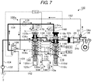
- FIG. 7 is a view of a first circuit state of the shift control device 100 that corresponds to a neutral range.
- the transmission control unit TCU energizes the first control valve 160 and holds the first control valve 160 at the illustrated open position while controlling the second control valve 170 to be unenergized and holding the second control valve 170 at the illustrated close position.
- the transmission control unit TCU fully closes the linear valve 106 so as to shut off the second supply oil passage 104 b .
- the circuit state of the hydraulic circuit 100 a is as illustrated in FIG. 7 .
- the state of the hydraulic circuit 100 a illustrated in FIG. 7 will be referred to as a first neutral circuit state.
- the energized conditions of the first control valve 160 and the second control valve 170 are the same, and only a controlled condition of the linear valve 106 differs.
- the first neutral circuit state is the same as the first drive circuit state described above in terms of the positions (the states) of the first switching valve 110 and the second switching valve 120 and only differs from the first drive circuit state in a point that the linear valve 106 is in the fully closed state.
- the hydraulic oil that is discharged from the pump 102 is delivered as indicated by solid arrows and bold lines.
- the linear valve 106 is fully closed, and the supply of the hydraulic oil to the downstream side of the linear valve 106 in the second supply oil passage 104 b is stopped.
- the first control valve 160 is held at the open position, and the pilot pressure is applied to the pilot chamber 110 b .
- the first switching valve 110 is held at the switch position against the urging force of the spring 110 d .
- the second control valve 170 is held at the close position, and the pilot pressure is not applied to the pilot chamber 120 b .
- the second switching valve 120 is held at the illustrated initial position by the urging force of the spring 120 d.
- the ports b, c, d communicate with each other.
- the ports k, m communicate with each other. Accordingly, the hydraulic oil that is supplied to the first supply oil passage 104 a is supplied to the hydraulic chamber 22 b via the ports k, m of the second switching valve 120 , the third coupling oil passage 136 , the ports d, c of the first switching valve 110 , and the actuator oil passage 150 .
- the piston 24 is projected as illustrated, and the parking lock mechanism 1 is held in the release state (see FIGS. 2A and 2B ).
- the linear valve 106 in the fully closed state, and the downstream side thereof in the second supply oil passage 104 b is coupled to the tank passage 108 .
- the hydraulic oil in the actuation chamber 34 a is recirculated into the tank T via the transmission oil passage 152 , the second supply oil passage 104 b , the linear valve 106 , and the tank passage 108 .
- the holding member 36 is accommodated in the actuation chamber 34 a , and the holding pin 32 is brought into an unlocked state where the holding pin 32 is detached from the locking groove 24 b.
- the hydraulic oil is recirculated into the tank T from the reverse brake REB.
- the ports f, g communicate with each other.
- the ports s, t communicate with each other.
- the reverse brake REB communicates with the drain oil passage 142 via the actuator oil passage 148 , the first switching valve 110 , the fourth coupling oil passage 138 , and the second switching valve 120 . In this way, the reverse brake REB is brought into a disengaged state.
- the forward clutch FWC communicates with the drain oil passage 142 via the actuator oil passage 146 , the first switching valve 110 , the fifth coupling oil passage 140 , the second switching valve 120 , the second supply oil passage 104 b , the linear valve 106 , and the tank passage 108 . In this way, the forward clutch FWC is brought into a disengaged state.
- the shift control device 100 of the present example when the shift position of the shift lever is switched to the parking range, the circuit state of the hydraulic circuit 100 a is switched to the parking circuit state in FIG. 4 .
- the circuit state of the hydraulic circuit 100 a is respectively switched to the reverse circuit state in FIG. 5 , the first drive circuit state in FIG. 6 , and the first neutral circuit state in FIG. 7 .
- Each of the above circuit states is switched when the transmission control unit TCU switches the positions or the states of the first switching valve 110 , the second switching valve 120 , and the linear valve 106 in accordance with the shift position of the shift lever. That is, the shift control device 100 is of the shift-by-wire type in which the circuit state of the hydraulic circuit 100 a is electrically switched.
- the shift control device 100 has a second drive circuit state of the hydraulic circuit 100 a .
- the transmission control unit TCU switches the hydraulic circuit 100 a to the second drive circuit state.
- FIG. 8 is a view of the second circuit state of the shift control device 100 that corresponds to the drive range.
- the transmission control unit TCU controls the first control valve 160 to be unenergized and holds the first control valve 160 at the illustrated close position while energizing the second control valve 170 and holding the second control valve 170 at the illustrated open position.
- the transmission control unit TCU calculates the required hydraulic pressure for each of the hydraulic oil supply targets and controls the opening degree of the linear valve 106 in accordance with the calculation result.
- the circuit state of the hydraulic circuit 100 a is as illustrated in FIG. 8 .
- the state of the hydraulic circuit 100 a illustrated in FIG. 8 will be referred to as the second drive circuit state.
- the hydraulic oil that is discharged from the pump 102 is delivered as indicated by solid arrows and bold lines.
- the linear valve 106 controls the pressure, and the hydraulic oil is supplied to the downstream side of the linear valve 106 in the second supply oil passage 104 b .
- the hydraulic oil in the second supply oil passage 104 b is supplied to the actuation chamber 34 a via the transmission oil passage 152 .
- the hydraulic oil in the second supply oil passage 104 b is also supplied to the second switching valve 120 from the port r.
- the first control valve 160 is held at the close position, and the pilot pressure is not applied to the pilot chamber 110 b .
- the first switching valve 110 is held at the illustrated initial position by the urging force of the spring 110 d .
- the second control valve 170 is held at the open position, and the pilot pressure is applied to the pilot chamber 120 b .
- the second switching valve 120 is held at the switch position against the urging force of the spring 120 d.
- the ports b, c communicate with each other, and the ports g, h communicate with each other.
- the ports j, k communicate with each other, and the ports r, s communicate with each other. Accordingly, the hydraulic oil that is supplied to the first supply oil passage 104 a is supplied to the hydraulic chamber 22 b via the ports k, j of the second switching valve 120 , the second coupling oil passage 134 , the ports b, c of the first switching valve 110 , and the actuator oil passage 150 .
- the hydraulic oil that is supplied to the second supply oil passage 104 b is supplied to the forward clutch FWC via the ports r, s of the second switching valve 120 , the fourth coupling oil passage 138 , the ports g, h of the first switching valve 110 , and the actuator oil passage 146 .
- the forward clutch FWC is engaged, and the vehicle can travel forward.
- the hydraulic oil is recirculated into the tank T from the reverse brake REB.
- the ports f, e communicate with each other.
- the reverse brake REB communicates with the drain oil passage 142 via the actuator oil passage 148 and the first switching valve 110 . In this way, the reverse brake REB is brought into a disengaged state.
- the actuator oil passage 148 and the drain oil passage 142 are held at the set pressure of each of the pressure holding valves 144 .
- the responsiveness at the time when the shift position of the shift lever is switched from the drive range to the reverse range can be improved.
- the shift control device 100 has a second neutral circuit state of the hydraulic circuit 100 a .
- the transmission control unit TCU switches the hydraulic circuit 100 a to the second neutral circuit state.
- FIG. 9 is a view of a second circuit state of the shift control device 100 that corresponds to the neutral range.
- the transmission control unit TCU controls the first control valve 160 to be unenergized and holds the first control valve 160 at the illustrated close position while energizing the second control valve 170 and holding the second control valve 170 at the illustrated open position.
- the transmission control unit TCU fully closes the linear valve 106 so as to shut off the second supply oil passage 104 b .
- the circuit state of the hydraulic circuit 100 a is as illustrated in FIG. 9 .
- the state of the hydraulic circuit 100 a illustrated in FIG. 9 will be referred to as the second neutral circuit state.
- the second neutral circuit state is the same as the second drive circuit state described above in terms of the positions (the states) of the first switching valve 110 and the second switching valve 120 and only differs from the second drive circuit state in the point that the linear valve 106 is in the fully closed state.
- the hydraulic oil that is discharged from the pump 102 is delivered as indicated by solid arrows and bold lines.
- the linear valve 106 is fully closed, and the supply of the hydraulic oil to the downstream side of the linear valve 106 in the second supply oil passage 104 b is stopped.
- the first control valve 160 is held at the close position, and the pilot pressure is not applied to the pilot chamber 110 b .
- the first switching valve 110 is held at the illustrated initial position by the urging force of the spring 110 d .
- the second control valve 170 is held at the open position, and the pilot pressure is applied to the pilot chamber 120 b .
- the second switching valve 120 is held at the switch position against the urging force of the spring 120 d.
- the ports b, c communicate with each other.
- the ports j, k communicate with each other. Accordingly, the hydraulic oil that is supplied to the first supply oil passage 104 a is supplied to the hydraulic chamber 22 b via the ports k, j of the second switching valve 120 , the second coupling oil passage 134 , the ports b, c of the first switching valve 110 , and the actuator oil passage 150 .
- the piston 24 is projected as illustrated, and the parking lock mechanism 1 is held in the release state (see FIGS. 2A and 2B ).
- the linear valve 106 in the fully closed state, and the downstream side thereof in the second supply oil passage 104 b is coupled to the tank passage 108 .
- the hydraulic oil in the actuation chamber 34 a is recirculated into the tank T via the transmission oil passage 152 , the second supply oil passage 104 b , the linear valve 106 , and the tank passage 108 .
- the holding member 36 is accommodated in the actuation chamber 34 a , and the holding pin 32 is brought into an unlocked state where the holding pin 32 is detached from the locking groove 24 b.
- the hydraulic oil is recirculated into the tank T from the reverse brake REB.
- the ports f, e communicate with each other.
- the reverse brake REB communicates with the drain oil passage 142 via the actuator oil passage 148 and the first switching valve 110 . In this way, the reverse brake REB is brought into a disengaged state.
- the forward clutch FWC communicates with the drain oil passage 142 via the actuator oil passage 146 , the first switching valve 110 , the fourth coupling oil passage 138 , the second switching valve 120 , the second supply oil passage 104 b , the linear valve 106 , and the tank passage 108 . In this way, the forward clutch FWC is brought into a disengaged state.
- the hydraulic circuit 100 a is configured to be switchable between the first drive circuit state and the second drive circuit state. In this way, even when the malfunction occurs to the first control valve 160 or the second control valve 170 , the vehicle can travel to the safe place.
- the hydraulic circuit 100 a is configured to be switchable between the first neutral circuit state and the second neutral circuit state. In this way, even when the malfunction occurs to the first control valve 160 or the second control valve 170 , the vehicle can be pulled over safely.
- the pressure holding valves 144 each of which holds the pressure of the drain oil passage 142 at the predetermined pressure, are provided.
- the hydraulic pressures of the actuator oil passage 146 , the actuator oil passage 148 , and further the hydraulic oil supply targets are held to be equal to or higher than the predetermined pressure.
- the responsiveness can be improved.
- the pressure holding valves 144 are provided in parallel in the drain oil passage 142 .
- the hydraulic oil can reliably be drained.
- the circuit configuration of the hydraulic circuit 100 a in the above example is merely one instance, and the design thereof can appropriately be modified.
- the first switching valve 110 is held at the switch position when the first control valve 160 is in the energized state, and the first switching valve 110 is held at the initial position when the first control valve 160 is in the unenergized state.
- the second switching valve 120 is held at the switch position when the second control valve 170 is in the energized state, and the second switching valve 120 is held at the initial position when the second control valve 170 is in the unenergized state.
- the first switching valve 110 (the second switching valve 120 ) may be held at the initial position when the first control valve 160 (the second control valve 170 ) is in the energized state, and the first switching valve 110 (the second switching valve 120 ) may be held at the switch position when the first control valve 160 (the second control valve 170 ) is in the unenergized state.
- the hydraulic circuit 100 a includes the linear valve 106 that can be switched between the opened state where the pump 102 can be coupled to the forward clutch FWC and the reverse brake REB and the closed state where the pump 102 cannot be coupled to the forward clutch FWC and the reverse brake REB.
- the hydraulic circuit 100 a includes the first switching valve 110 and the second switching valve 120 , each of which can be switched between the initial position and the switch position. In the first drive circuit state and the second drive circuit state where the positions of the first switching valve 110 and the second switching valve 120 are the same but the opened/closed state of the linear valve 106 differs, the pump 102 is coupled to the same forward clutch FWC in the continuously variable transmission.
- a hydraulic circuit that is provided with multiple actuation valves and a control unit that switches positions or states of each of the multiple actuation valves in accordance with the shift position of the shift lever may be provided.
- the hydraulic circuit may couple the hydraulic oil supply source to the same travel actuator in the continuously variable transmission.
- the first switching valve 110 , the second switching valve 120 , and the linear valve 106 are provided as the multiple actuation valves in the above example, the number and the configurations of the actuation valves are not limited to those in the above example.
- each of the first switching valve 110 and the second switching valve 120 may be switched among three or more positions, and the linear valve 106 may be constructed of a valve body that opens/closes the circuit.
- the first drive circuit state and the second drive circuit state are respectively provided as a first travel circuit state and a second travel circuit state.
- a first reverse circuit state and a second reverse circuit state may respectively be provided as the first travel circuit state and the second travel circuit state. That is, the travel actuator is not limited to the forward clutch FWC but may be the reverse brake REB.
- the first neutral circuit state and the second neutral circuit state are respectively provided as a first stop circuit state and a second stop circuit state.
- a first parking circuit state and a second parking circuit state may respectively be provided as the first stop circuit state and the second stop circuit state.
- only one stop circuit state may be provided.
- the shift control device 100 controls the parking lock mechanism 1 .
- the parking lock mechanism 1 is not an essential component.
- the range switching operation may be performed by using a push-button, a dial, a touchscreen, or the like, for instance, and the configuration of the shift operation device is not limited to that described in the above example.
- the present invention is also applicable to other automatic transmissions such as a planetary AT.
- the vehicle can reliably be evacuated to the safe place.
- the present invention can be used for the shift control device used for the vehicle.
Landscapes
- Engineering & Computer Science (AREA)
- General Engineering & Computer Science (AREA)
- Mechanical Engineering (AREA)
- Physics & Mathematics (AREA)
- Fluid Mechanics (AREA)
- Chemical & Material Sciences (AREA)
- Analytical Chemistry (AREA)
- Control Of Transmission Device (AREA)
- Gear-Shifting Mechanisms (AREA)
Abstract
Description
Claims (13)
Applications Claiming Priority (2)
| Application Number | Priority Date | Filing Date | Title |
|---|---|---|---|
| JP2017180491A JP6594386B2 (en) | 2017-09-20 | 2017-09-20 | Shift control device |
| JP2017-180491 | 2017-09-20 |
Publications (2)
| Publication Number | Publication Date |
|---|---|
| US20190085975A1 US20190085975A1 (en) | 2019-03-21 |
| US10907732B2 true US10907732B2 (en) | 2021-02-02 |
Family
ID=65719198
Family Applications (1)
| Application Number | Title | Priority Date | Filing Date |
|---|---|---|---|
| US15/996,187 Active 2039-03-13 US10907732B2 (en) | 2017-09-20 | 2018-06-01 | Shift control device |
Country Status (3)
| Country | Link |
|---|---|
| US (1) | US10907732B2 (en) |
| JP (1) | JP6594386B2 (en) |
| CN (1) | CN109519533B (en) |
Families Citing this family (2)
| Publication number | Priority date | Publication date | Assignee | Title |
|---|---|---|---|---|
| JP7189700B2 (en) * | 2018-08-28 | 2022-12-14 | 株式会社Subaru | shift control device |
| DE102020203132A1 (en) * | 2020-03-11 | 2021-09-16 | Zf Friedrichshafen Ag | Valve arrangement for a hydraulic control unit of a transmission of a motor vehicle |
Citations (9)
| Publication number | Priority date | Publication date | Assignee | Title |
|---|---|---|---|---|
| JPH05223156A (en) | 1992-02-12 | 1993-08-31 | Toyota Motor Corp | Shift control device for shift-by-wire automatic transmission |
| US5409434A (en) | 1992-01-30 | 1995-04-25 | Toyota Jidosha Kabushiki Kaisha | Control system with failsafe for shift-by-wire automatic transmission |
| JP2008290575A (en) | 2007-05-24 | 2008-12-04 | Toyota Motor Corp | Control device for shift switching mechanism |
| US20100099537A1 (en) * | 2008-10-21 | 2010-04-22 | Gm Global Technology Operations, Inc. | Control system for dual clutch transmission |
| US7954394B2 (en) * | 2007-09-12 | 2011-06-07 | Aisin Aw Co., Ltd. | Range switching device |
| US20130220052A1 (en) | 2012-02-29 | 2013-08-29 | Fuji Jukogyo Kabushiki Kaisha | Range switching device |
| JP2014055624A (en) | 2012-09-12 | 2014-03-27 | Jatco Ltd | Automatic transmission |
| US9759314B2 (en) * | 2013-09-30 | 2017-09-12 | Aisin Aw Co., Ltd. | Hydraulic control apparatus |
| US9958066B2 (en) * | 2014-01-23 | 2018-05-01 | Aisin Aw Co., Ltd. | Range switching device |
Family Cites Families (2)
| Publication number | Priority date | Publication date | Assignee | Title |
|---|---|---|---|---|
| JP2004316862A (en) * | 2003-04-18 | 2004-11-11 | Aisin Aw Co Ltd | Range switching device for vehicle |
| CN104265876B (en) * | 2014-08-05 | 2016-07-13 | 潍柴动力股份有限公司 | Method for diagnosing faults that a kind of Clutch Control is failed and system |
-
2017
- 2017-09-20 JP JP2017180491A patent/JP6594386B2/en not_active Expired - Fee Related
-
2018
- 2018-06-01 US US15/996,187 patent/US10907732B2/en active Active
- 2018-07-17 CN CN201810782999.8A patent/CN109519533B/en not_active Expired - Fee Related
Patent Citations (11)
| Publication number | Priority date | Publication date | Assignee | Title |
|---|---|---|---|---|
| US5409434A (en) | 1992-01-30 | 1995-04-25 | Toyota Jidosha Kabushiki Kaisha | Control system with failsafe for shift-by-wire automatic transmission |
| US5505674A (en) | 1992-01-30 | 1996-04-09 | Toyoda Jidosha Kabushiki Kaisha | Control system with failsafe range passages in a changeover valve for shift-by-wire automatic transmission |
| JPH05223156A (en) | 1992-02-12 | 1993-08-31 | Toyota Motor Corp | Shift control device for shift-by-wire automatic transmission |
| JP2008290575A (en) | 2007-05-24 | 2008-12-04 | Toyota Motor Corp | Control device for shift switching mechanism |
| US7954394B2 (en) * | 2007-09-12 | 2011-06-07 | Aisin Aw Co., Ltd. | Range switching device |
| US20100099537A1 (en) * | 2008-10-21 | 2010-04-22 | Gm Global Technology Operations, Inc. | Control system for dual clutch transmission |
| US20130220052A1 (en) | 2012-02-29 | 2013-08-29 | Fuji Jukogyo Kabushiki Kaisha | Range switching device |
| JP2013177953A (en) | 2012-02-29 | 2013-09-09 | Fuji Heavy Ind Ltd | Range switching device |
| JP2014055624A (en) | 2012-09-12 | 2014-03-27 | Jatco Ltd | Automatic transmission |
| US9759314B2 (en) * | 2013-09-30 | 2017-09-12 | Aisin Aw Co., Ltd. | Hydraulic control apparatus |
| US9958066B2 (en) * | 2014-01-23 | 2018-05-01 | Aisin Aw Co., Ltd. | Range switching device |
Non-Patent Citations (1)
| Title |
|---|
| Japanese Office Action, dated Mar. 19, 2019, in Japanese Application No. 2017-180491 and English Translation thereof. |
Also Published As
| Publication number | Publication date |
|---|---|
| JP2019056407A (en) | 2019-04-11 |
| CN109519533A (en) | 2019-03-26 |
| CN109519533B (en) | 2021-11-02 |
| JP6594386B2 (en) | 2019-10-23 |
| US20190085975A1 (en) | 2019-03-21 |
Similar Documents
| Publication | Publication Date | Title |
|---|---|---|
| US10234034B2 (en) | Parking lock apparatus | |
| US10408284B2 (en) | Hydraulic system for a vehicle | |
| JP4602335B2 (en) | Pressure supply valve | |
| CA2940809C (en) | Vehicular parking lock device | |
| US10591052B2 (en) | Shift control device | |
| CN109312858B (en) | Device for actuating a parking lock of an automatic transmission and a parking lock mechanism for such an automatic transmission | |
| US10907732B2 (en) | Shift control device | |
| US8371552B2 (en) | Shift actuator valve having a pressure dead band | |
| JP6410257B2 (en) | Hydraulic control device for automatic transmission | |
| US10139008B2 (en) | Solenoid spool valve | |
| JP6592300B2 (en) | Solenoid valve with check valve with bypass passage | |
| JP2017166637A (en) | Parking actuator valve | |
| JP2018047824A (en) | Park lock device | |
| JP6817866B2 (en) | Shift control device | |
| JP6767911B2 (en) | Shift control device | |
| US4883092A (en) | Multi-way control valve apparatus | |
| JP6799440B2 (en) | transmission | |
| JP7189700B2 (en) | shift control device | |
| WO2019053783A1 (en) | Control valve | |
| JPS60256655A (en) | Oil pressure controlling device for automatic transmission | |
| JP2019019853A (en) | Oil passage selecting device | |
| JP2019019856A (en) | Range switching device | |
| JP2019019855A (en) | Range switching device | |
| US20090294722A1 (en) | Contamination and flow control | |
| JP2019044799A (en) | Power transmission device of vehicle |
Legal Events
| Date | Code | Title | Description |
|---|---|---|---|
| FEPP | Fee payment procedure |
Free format text: ENTITY STATUS SET TO UNDISCOUNTED (ORIGINAL EVENT CODE: BIG.); ENTITY STATUS OF PATENT OWNER: LARGE ENTITY |
|
| AS | Assignment |
Owner name: SUBARU CORPORATION, JAPAN Free format text: ASSIGNMENT OF ASSIGNORS INTEREST;ASSIGNORS:KIDACHI, DAISUKE;MURAKAMI, MAMORU;TSUJI, TAICHI;REEL/FRAME:045972/0883 Effective date: 20180320 |
|
| STPP | Information on status: patent application and granting procedure in general |
Free format text: DOCKETED NEW CASE - READY FOR EXAMINATION |
|
| STPP | Information on status: patent application and granting procedure in general |
Free format text: NON FINAL ACTION MAILED |
|
| STPP | Information on status: patent application and granting procedure in general |
Free format text: RESPONSE TO NON-FINAL OFFICE ACTION ENTERED AND FORWARDED TO EXAMINER |
|
| STPP | Information on status: patent application and granting procedure in general |
Free format text: NOTICE OF ALLOWANCE MAILED -- APPLICATION RECEIVED IN OFFICE OF PUBLICATIONS |
|
| STPP | Information on status: patent application and granting procedure in general |
Free format text: PUBLICATIONS -- ISSUE FEE PAYMENT RECEIVED |
|
| STCF | Information on status: patent grant |
Free format text: PATENTED CASE |
|
| MAFP | Maintenance fee payment |
Free format text: PAYMENT OF MAINTENANCE FEE, 4TH YEAR, LARGE ENTITY (ORIGINAL EVENT CODE: M1551); ENTITY STATUS OF PATENT OWNER: LARGE ENTITY Year of fee payment: 4 |