US10907660B2 - Hydraulic circuit for feeding an actuator, in particular for use in moving a door of an aircraft bay - Google Patents
Hydraulic circuit for feeding an actuator, in particular for use in moving a door of an aircraft bay Download PDFInfo
- Publication number
- US10907660B2 US10907660B2 US16/504,403 US201916504403A US10907660B2 US 10907660 B2 US10907660 B2 US 10907660B2 US 201916504403 A US201916504403 A US 201916504403A US 10907660 B2 US10907660 B2 US 10907660B2
- Authority
- US
- United States
- Prior art keywords
- chamber
- valve
- actuator
- slide
- door
- Prior art date
- Legal status (The legal status is an assumption and is not a legal conclusion. Google has not performed a legal analysis and makes no representation as to the accuracy of the status listed.)
- Active
Links
Images


Classifications
-
- B—PERFORMING OPERATIONS; TRANSPORTING
- B64—AIRCRAFT; AVIATION; COSMONAUTICS
- B64C—AEROPLANES; HELICOPTERS
- B64C1/00—Fuselages; Constructional features common to fuselages, wings, stabilising surfaces or the like
- B64C1/14—Windows; Doors; Hatch covers or access panels; Surrounding frame structures; Canopies; Windscreens accessories therefor, e.g. pressure sensors, water deflectors, hinges, seals, handles, latches, windscreen wipers
- B64C1/1407—Doors; surrounding frames
-
- F—MECHANICAL ENGINEERING; LIGHTING; HEATING; WEAPONS; BLASTING
- F15—FLUID-PRESSURE ACTUATORS; HYDRAULICS OR PNEUMATICS IN GENERAL
- F15B—SYSTEMS ACTING BY MEANS OF FLUIDS IN GENERAL; FLUID-PRESSURE ACTUATORS, e.g. SERVOMOTORS; DETAILS OF FLUID-PRESSURE SYSTEMS, NOT OTHERWISE PROVIDED FOR
- F15B11/00—Servomotor systems without provision for follow-up action; Circuits therefor
- F15B11/003—Systems with load-holding valves
-
- F—MECHANICAL ENGINEERING; LIGHTING; HEATING; WEAPONS; BLASTING
- F15—FLUID-PRESSURE ACTUATORS; HYDRAULICS OR PNEUMATICS IN GENERAL
- F15B—SYSTEMS ACTING BY MEANS OF FLUIDS IN GENERAL; FLUID-PRESSURE ACTUATORS, e.g. SERVOMOTORS; DETAILS OF FLUID-PRESSURE SYSTEMS, NOT OTHERWISE PROVIDED FOR
- F15B11/00—Servomotor systems without provision for follow-up action; Circuits therefor
- F15B11/08—Servomotor systems without provision for follow-up action; Circuits therefor with only one servomotor
- F15B11/10—Servomotor systems without provision for follow-up action; Circuits therefor with only one servomotor in which the servomotor position is a function of the pressure also pressure regulators as operating means for such systems, the device itself may be a position indicating system
-
- E—FIXED CONSTRUCTIONS
- E05—LOCKS; KEYS; WINDOW OR DOOR FITTINGS; SAFES
- E05F—DEVICES FOR MOVING WINGS INTO OPEN OR CLOSED POSITION; CHECKS FOR WINGS; WING FITTINGS NOT OTHERWISE PROVIDED FOR, CONCERNED WITH THE FUNCTIONING OF THE WING
- E05F15/00—Power-operated mechanisms for wings
- E05F15/50—Power-operated mechanisms for wings using fluid-pressure actuators
- E05F15/53—Power-operated mechanisms for wings using fluid-pressure actuators for swinging wings
-
- F—MECHANICAL ENGINEERING; LIGHTING; HEATING; WEAPONS; BLASTING
- F15—FLUID-PRESSURE ACTUATORS; HYDRAULICS OR PNEUMATICS IN GENERAL
- F15B—SYSTEMS ACTING BY MEANS OF FLUIDS IN GENERAL; FLUID-PRESSURE ACTUATORS, e.g. SERVOMOTORS; DETAILS OF FLUID-PRESSURE SYSTEMS, NOT OTHERWISE PROVIDED FOR
- F15B13/00—Details of servomotor systems ; Valves for servomotor systems
- F15B13/02—Fluid distribution or supply devices characterised by their adaptation to the control of servomotors
- F15B13/04—Fluid distribution or supply devices characterised by their adaptation to the control of servomotors for use with a single servomotor
- F15B13/0401—Valve members; Fluid interconnections therefor
-
- F—MECHANICAL ENGINEERING; LIGHTING; HEATING; WEAPONS; BLASTING
- F15—FLUID-PRESSURE ACTUATORS; HYDRAULICS OR PNEUMATICS IN GENERAL
- F15B—SYSTEMS ACTING BY MEANS OF FLUIDS IN GENERAL; FLUID-PRESSURE ACTUATORS, e.g. SERVOMOTORS; DETAILS OF FLUID-PRESSURE SYSTEMS, NOT OTHERWISE PROVIDED FOR
- F15B13/00—Details of servomotor systems ; Valves for servomotor systems
- F15B13/02—Fluid distribution or supply devices characterised by their adaptation to the control of servomotors
- F15B13/04—Fluid distribution or supply devices characterised by their adaptation to the control of servomotors for use with a single servomotor
- F15B13/042—Fluid distribution or supply devices characterised by their adaptation to the control of servomotors for use with a single servomotor operated by fluid pressure
-
- E—FIXED CONSTRUCTIONS
- E05—LOCKS; KEYS; WINDOW OR DOOR FITTINGS; SAFES
- E05Y—INDEXING SCHEME RELATING TO HINGES OR OTHER SUSPENSION DEVICES FOR DOORS, WINDOWS OR WINGS AND DEVICES FOR MOVING WINGS INTO OPEN OR CLOSED POSITION, CHECKS FOR WINGS AND WING FITTINGS NOT OTHERWISE PROVIDED FOR, CONCERNED WITH THE FUNCTIONING OF THE WING
- E05Y2900/00—Application of doors, windows, wings or fittings thereof
- E05Y2900/50—Application of doors, windows, wings or fittings thereof for vehicles
- E05Y2900/53—Application of doors, windows, wings or fittings thereof for vehicles characterised by the type of wing
- E05Y2900/531—Doors
-
- F—MECHANICAL ENGINEERING; LIGHTING; HEATING; WEAPONS; BLASTING
- F15—FLUID-PRESSURE ACTUATORS; HYDRAULICS OR PNEUMATICS IN GENERAL
- F15B—SYSTEMS ACTING BY MEANS OF FLUIDS IN GENERAL; FLUID-PRESSURE ACTUATORS, e.g. SERVOMOTORS; DETAILS OF FLUID-PRESSURE SYSTEMS, NOT OTHERWISE PROVIDED FOR
- F15B11/00—Servomotor systems without provision for follow-up action; Circuits therefor
- F15B11/02—Systems essentially incorporating special features for controlling the speed or actuating force of an output member
- F15B11/024—Systems essentially incorporating special features for controlling the speed or actuating force of an output member by means of differential connection of the servomotor lines, e.g. regenerative circuits
-
- F—MECHANICAL ENGINEERING; LIGHTING; HEATING; WEAPONS; BLASTING
- F15—FLUID-PRESSURE ACTUATORS; HYDRAULICS OR PNEUMATICS IN GENERAL
- F15B—SYSTEMS ACTING BY MEANS OF FLUIDS IN GENERAL; FLUID-PRESSURE ACTUATORS, e.g. SERVOMOTORS; DETAILS OF FLUID-PRESSURE SYSTEMS, NOT OTHERWISE PROVIDED FOR
- F15B13/00—Details of servomotor systems ; Valves for servomotor systems
- F15B13/02—Fluid distribution or supply devices characterised by their adaptation to the control of servomotors
- F15B13/04—Fluid distribution or supply devices characterised by their adaptation to the control of servomotors for use with a single servomotor
- F15B13/0401—Valve members; Fluid interconnections therefor
- F15B13/0407—Means for damping the valve member movement
-
- F—MECHANICAL ENGINEERING; LIGHTING; HEATING; WEAPONS; BLASTING
- F15—FLUID-PRESSURE ACTUATORS; HYDRAULICS OR PNEUMATICS IN GENERAL
- F15B—SYSTEMS ACTING BY MEANS OF FLUIDS IN GENERAL; FLUID-PRESSURE ACTUATORS, e.g. SERVOMOTORS; DETAILS OF FLUID-PRESSURE SYSTEMS, NOT OTHERWISE PROVIDED FOR
- F15B13/00—Details of servomotor systems ; Valves for servomotor systems
- F15B13/02—Fluid distribution or supply devices characterised by their adaptation to the control of servomotors
- F15B13/04—Fluid distribution or supply devices characterised by their adaptation to the control of servomotors for use with a single servomotor
- F15B13/0401—Valve members; Fluid interconnections therefor
- F15B2013/0412—Valve members; Fluid interconnections therefor with three positions
-
- F—MECHANICAL ENGINEERING; LIGHTING; HEATING; WEAPONS; BLASTING
- F15—FLUID-PRESSURE ACTUATORS; HYDRAULICS OR PNEUMATICS IN GENERAL
- F15B—SYSTEMS ACTING BY MEANS OF FLUIDS IN GENERAL; FLUID-PRESSURE ACTUATORS, e.g. SERVOMOTORS; DETAILS OF FLUID-PRESSURE SYSTEMS, NOT OTHERWISE PROVIDED FOR
- F15B21/00—Common features of fluid actuator systems; Fluid-pressure actuator systems or details thereof, not covered by any other group of this subclass
- F15B21/10—Delay devices or arrangements
-
- F—MECHANICAL ENGINEERING; LIGHTING; HEATING; WEAPONS; BLASTING
- F15—FLUID-PRESSURE ACTUATORS; HYDRAULICS OR PNEUMATICS IN GENERAL
- F15B—SYSTEMS ACTING BY MEANS OF FLUIDS IN GENERAL; FLUID-PRESSURE ACTUATORS, e.g. SERVOMOTORS; DETAILS OF FLUID-PRESSURE SYSTEMS, NOT OTHERWISE PROVIDED FOR
- F15B2211/00—Circuits for servomotor systems
- F15B2211/20—Fluid pressure source, e.g. accumulator or variable axial piston pump
- F15B2211/255—Flow control functions
-
- F—MECHANICAL ENGINEERING; LIGHTING; HEATING; WEAPONS; BLASTING
- F15—FLUID-PRESSURE ACTUATORS; HYDRAULICS OR PNEUMATICS IN GENERAL
- F15B—SYSTEMS ACTING BY MEANS OF FLUIDS IN GENERAL; FLUID-PRESSURE ACTUATORS, e.g. SERVOMOTORS; DETAILS OF FLUID-PRESSURE SYSTEMS, NOT OTHERWISE PROVIDED FOR
- F15B2211/00—Circuits for servomotor systems
- F15B2211/30—Directional control
- F15B2211/305—Directional control characterised by the type of valves
- F15B2211/30505—Non-return valves, i.e. check valves
- F15B2211/30515—Load holding valves
-
- F—MECHANICAL ENGINEERING; LIGHTING; HEATING; WEAPONS; BLASTING
- F15—FLUID-PRESSURE ACTUATORS; HYDRAULICS OR PNEUMATICS IN GENERAL
- F15B—SYSTEMS ACTING BY MEANS OF FLUIDS IN GENERAL; FLUID-PRESSURE ACTUATORS, e.g. SERVOMOTORS; DETAILS OF FLUID-PRESSURE SYSTEMS, NOT OTHERWISE PROVIDED FOR
- F15B2211/00—Circuits for servomotor systems
- F15B2211/30—Directional control
- F15B2211/31—Directional control characterised by the positions of the valve element
- F15B2211/3105—Neutral or centre positions
- F15B2211/3111—Neutral or centre positions the pump port being closed in the centre position, e.g. so-called closed centre
-
- F—MECHANICAL ENGINEERING; LIGHTING; HEATING; WEAPONS; BLASTING
- F15—FLUID-PRESSURE ACTUATORS; HYDRAULICS OR PNEUMATICS IN GENERAL
- F15B—SYSTEMS ACTING BY MEANS OF FLUIDS IN GENERAL; FLUID-PRESSURE ACTUATORS, e.g. SERVOMOTORS; DETAILS OF FLUID-PRESSURE SYSTEMS, NOT OTHERWISE PROVIDED FOR
- F15B2211/00—Circuits for servomotor systems
- F15B2211/30—Directional control
- F15B2211/31—Directional control characterised by the positions of the valve element
- F15B2211/3122—Special positions other than the pump port being connected to working ports or the working ports being connected to the return line
- F15B2211/3127—Floating position connecting the working ports and the return line
-
- F—MECHANICAL ENGINEERING; LIGHTING; HEATING; WEAPONS; BLASTING
- F15—FLUID-PRESSURE ACTUATORS; HYDRAULICS OR PNEUMATICS IN GENERAL
- F15B—SYSTEMS ACTING BY MEANS OF FLUIDS IN GENERAL; FLUID-PRESSURE ACTUATORS, e.g. SERVOMOTORS; DETAILS OF FLUID-PRESSURE SYSTEMS, NOT OTHERWISE PROVIDED FOR
- F15B2211/00—Circuits for servomotor systems
- F15B2211/30—Directional control
- F15B2211/31—Directional control characterised by the positions of the valve element
- F15B2211/3122—Special positions other than the pump port being connected to working ports or the working ports being connected to the return line
- F15B2211/3133—Regenerative position connecting the working ports or connecting the working ports to the pump, e.g. for high-speed approach stroke
-
- F—MECHANICAL ENGINEERING; LIGHTING; HEATING; WEAPONS; BLASTING
- F15—FLUID-PRESSURE ACTUATORS; HYDRAULICS OR PNEUMATICS IN GENERAL
- F15B—SYSTEMS ACTING BY MEANS OF FLUIDS IN GENERAL; FLUID-PRESSURE ACTUATORS, e.g. SERVOMOTORS; DETAILS OF FLUID-PRESSURE SYSTEMS, NOT OTHERWISE PROVIDED FOR
- F15B2211/00—Circuits for servomotor systems
- F15B2211/40—Flow control
- F15B2211/405—Flow control characterised by the type of flow control means or valve
- F15B2211/40507—Flow control characterised by the type of flow control means or valve with constant throttles or orifices
-
- F—MECHANICAL ENGINEERING; LIGHTING; HEATING; WEAPONS; BLASTING
- F15—FLUID-PRESSURE ACTUATORS; HYDRAULICS OR PNEUMATICS IN GENERAL
- F15B—SYSTEMS ACTING BY MEANS OF FLUIDS IN GENERAL; FLUID-PRESSURE ACTUATORS, e.g. SERVOMOTORS; DETAILS OF FLUID-PRESSURE SYSTEMS, NOT OTHERWISE PROVIDED FOR
- F15B2211/00—Circuits for servomotor systems
- F15B2211/40—Flow control
- F15B2211/405—Flow control characterised by the type of flow control means or valve
- F15B2211/40576—Assemblies of multiple valves
- F15B2211/40584—Assemblies of multiple valves the flow control means arranged in parallel with a check valve
-
- F—MECHANICAL ENGINEERING; LIGHTING; HEATING; WEAPONS; BLASTING
- F15—FLUID-PRESSURE ACTUATORS; HYDRAULICS OR PNEUMATICS IN GENERAL
- F15B—SYSTEMS ACTING BY MEANS OF FLUIDS IN GENERAL; FLUID-PRESSURE ACTUATORS, e.g. SERVOMOTORS; DETAILS OF FLUID-PRESSURE SYSTEMS, NOT OTHERWISE PROVIDED FOR
- F15B2211/00—Circuits for servomotor systems
- F15B2211/40—Flow control
- F15B2211/405—Flow control characterised by the type of flow control means or valve
- F15B2211/40576—Assemblies of multiple valves
- F15B2211/40592—Assemblies of multiple valves with multiple valves in parallel flow paths
-
- F—MECHANICAL ENGINEERING; LIGHTING; HEATING; WEAPONS; BLASTING
- F15—FLUID-PRESSURE ACTUATORS; HYDRAULICS OR PNEUMATICS IN GENERAL
- F15B—SYSTEMS ACTING BY MEANS OF FLUIDS IN GENERAL; FLUID-PRESSURE ACTUATORS, e.g. SERVOMOTORS; DETAILS OF FLUID-PRESSURE SYSTEMS, NOT OTHERWISE PROVIDED FOR
- F15B2211/00—Circuits for servomotor systems
- F15B2211/40—Flow control
- F15B2211/415—Flow control characterised by the connections of the flow control means in the circuit
- F15B2211/41527—Flow control characterised by the connections of the flow control means in the circuit being connected to an output member and a directional control valve
-
- F—MECHANICAL ENGINEERING; LIGHTING; HEATING; WEAPONS; BLASTING
- F15—FLUID-PRESSURE ACTUATORS; HYDRAULICS OR PNEUMATICS IN GENERAL
- F15B—SYSTEMS ACTING BY MEANS OF FLUIDS IN GENERAL; FLUID-PRESSURE ACTUATORS, e.g. SERVOMOTORS; DETAILS OF FLUID-PRESSURE SYSTEMS, NOT OTHERWISE PROVIDED FOR
- F15B2211/00—Circuits for servomotor systems
- F15B2211/70—Output members, e.g. hydraulic motors or cylinders or control therefor
- F15B2211/705—Output members, e.g. hydraulic motors or cylinders or control therefor characterised by the type of output members or actuators
- F15B2211/7051—Linear output members
- F15B2211/7053—Double-acting output members
-
- F—MECHANICAL ENGINEERING; LIGHTING; HEATING; WEAPONS; BLASTING
- F15—FLUID-PRESSURE ACTUATORS; HYDRAULICS OR PNEUMATICS IN GENERAL
- F15B—SYSTEMS ACTING BY MEANS OF FLUIDS IN GENERAL; FLUID-PRESSURE ACTUATORS, e.g. SERVOMOTORS; DETAILS OF FLUID-PRESSURE SYSTEMS, NOT OTHERWISE PROVIDED FOR
- F15B2211/00—Circuits for servomotor systems
- F15B2211/80—Other types of control related to particular problems or conditions
- F15B2211/86—Control during or prevention of abnormal conditions
- F15B2211/8606—Control during or prevention of abnormal conditions the abnormal condition being a shock
Definitions
- the invention relates to a hydraulic circuit for feeding an actuator, in particular for use in moving a door of an aircraft bay, such as a wheel well, or indeed for moving an undercarriage.
- Aircraft bay doors are generally moved by an actuator between an open position and a closed position in which the doors are held locked by a latching box.
- the actuator continues to pull on the door after it has reached its closed position in order to press it against the abutment that defines the closed position and thus lock it in a prestressed state. Thereafter, once the door is locked, the actuator ceases to act.
- the procedure begins by retracting the actuator to pull the door so as to make it easier to open the latch in the latching box. Thereafter the actuator is caused to extend.
- the slide valve that feeds the actuator passes via a central position in which both chambers of the actuator are connected to return, thereby suddenly reducing the traction that the actuator exerts on the door.
- the pulling force applied to the door by the actuator is released suddenly and the corresponding prestress propels the door until the actuator is pressurized once more and controls the door again, with this propulsion leading to bouncing.
- This bouncing induces pressure peaks in the chambers of the actuator and in the associated pipework, which can be damaging in terms of the ability of the actuator and of the structure of the aircraft to withstand fatigue.
- the invention seeks to propose a hydraulic circuit for feeding an actuator that reduced the risk of the load coupled to the actuator bouncing in the event of the load being propelled by a sudden release of stress, or indeed by its own weight when reversing the travel direction of the actuator.
- a hydraulic circuit for feeding an actuator having first and second chambers comprising a slide valve with a slide that is movable between first and second extreme positions on either side of a stable central position so that:
- the hydraulic circuit includes pressure-maintaining means for maintaining pressure in the first chamber of the actuator while the slide is passing through the central position on being moved from the first extreme position to the second extreme position.
- the pressure-maintaining means prevent the first chamber of the actuator from depressurizing suddenly while the slide of the slide valve is passing through the central position, thereby keeping control over the load.
- the prestress can relax progressively without causing the load to move suddenly, thereby reducing any risk of bouncing.
- the pressure-maintaining means comprise an on/off valve arranged on a line connecting the slide valve to the first chamber, this on/off valve including a slide that is movable between a closed position and an open position towards which the slide is urged by a spring, the on/off valve having at least two pilot chambers, including an opening chamber connected to the second chamber of the actuator and a closing chamber connected to the first chamber of the actuator.
- the on/off valve is thus put into a closed position when the slide of the slide valve is in the first extreme position, thereby maintaining the first chamber of the actuator under pressure while the slide valve is passing through the central position as it passes from its first extreme position to its second extreme position. Thereafter, the on/off valve opens progressively under the action of the spring when the second chamber of the actuator is pressurized.
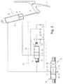
- FIG. 1 is a hydraulic circuit diagram showing how an actuator for moving a door is fed by means of a hydraulic circuit of the invention
- FIG. 2 is a timing chart showing various operating parameters of the hydraulic circuit of the invention during stages of opening and of closing the door, including:
- FIG. 3 is a hydraulic circuit diagram showing a variant embodiment of the invention.
- FIG. 4 is a hydraulic circuit diagram showing another variant embodiment of the invention.
- the hydraulic circuit diagram shown in FIG. 1 is for feeding hydraulic fluid to an actuator 1 comprising a cylinder 2 in which a rod 3 slides by being associated with a piston 4 that defines within the cylinder 2 both a first, or retraction, chamber 5 (in this example, the annular chamber) and also a second, or extension, chamber 6 (in this example, the complete chamber).
- the actuator 1 serves to move a door 7 of an aircraft wheel bay. In this example, the door is closed when the rod 3 of the actuator is in its retracted position.
- the two chambers 5 and 6 of the actuator 1 are fed with fluid under pressure by a slide valve 10 having a feed port 11 , a return port 12 , and service ports 13 and 14 connected respectively to the retraction chamber 5 and to the extension chamber 6 of the actuator 1 .
- the slide valve 10 comprises a cylinder in which a slide 16 is slidably mounted. The slide 16 is urged towards a stable central position 17 by centering springs. In this position, the slide 16 connects both of the service ports 13 and 14 to the return port 12 , such that both chambers 5 and 6 of the actuator 1 are connected to return.
- the slide 16 may be moved towards first and second extreme positions 18 and 19 on either side of the central position, such that:
- the feed port 11 is connected to the retraction chamber 5 and the return port 12 is connected to the extension chamber 6 , so as to pull on the door 7 in order to close it;
- the feed port 11 is connected, in this example, to both chambers 5 and 6 of the actuator 1 in order to open the door.
- the rod 3 of the actuator 1 is then extended as a result of the differential action of pressure in both chambers 5 and 6 .
- the door 7 is generally held closed by means of a latch of a latching box (not shown) that hooks onto a roller of the door 7 in order to hold the door in a prestressed position against a closed abutment.
- the pressure-maintaining means 20 comprise an on/off valve 21 arranged in the pipe connecting the slide valve 10 to the retraction chamber 5 .
- the on/off valve 21 has a slide 22 that is movable between a closed position 23 and an open position 24 towards which it is urged by a spring 25 .
- the on/off valve 21 has two opposing pilot chambers for moving the movable slide 22 (which chambers are represented by the standardized black triangle symbol), these chambers comprising a closing chamber 26 connected to the service port 13 that is connected to the retraction chamber 5 of the actuator, and an opening chamber 27 connected to the service port 14 that is connected to the extension chamber 6 of the actuator.
- connection between the service port 13 of the slide valve 10 and the closing chamber 26 of the on/off valve 21 includes a constriction R 1 and a check valve C 1 connected in parallel, the check valve C 1 allowing fluid to flow from the slide valve 10 towards the closing chamber 26 .
- the pressure-maintaining means 20 include a hydraulic shunt 29 that connects the retraction chamber 5 of the actuator directly to the service port 13 by shunting the on/off valve 21 in such a manner that the retraction chamber 5 can be fed when the on/off valve 21 is closed.
- the shunt 29 includes a constriction R 2 and a check valve C 2 connected in parallel, the check valve C 2 allowing fluid to flow from the slide valve 10 towards the retraction chamber 5 .
- FIG. 2 where the horizontal axis represents time and in which the various stages of an opening and closing sequence of a door on an aircraft are shown, which stages are as follows:
- the slide 16 of the valve 10 is initially taken to its first extreme position 18 , thereby pressurizing the retraction chamber 5 .
- the actuator 1 then exerts traction on the door 7 .
- the door is unlatched, after which the slide 16 of the valve 10 is taken to its second extreme position 19 in order to open the door 7 , with the pressure in the retraction chamber 5 being maintained, in a manner that is described in detail below.
- the actuator 1 pushes the door 7 as far as its open position. This stage is described in greater detail below;
- the slide 16 of the valve 10 is returned to the first extreme position 18 , thereby connecting the extension chamber 6 to return.
- the slide 16 passing through the central position 17 does not lead to sudden depressurizing of the retraction chamber 5 .
- the actuator 1 pulls the door 7 and returns it to the closed position.
- the latch latches the door 7 so as to hold it in the closed position while prestressed against its closed abutment.
- the slide 16 of the valve 10 is returned to its central position 17 , so that both chambers of the actuator 1 are connected to return.
- the opening stage is subdivided into three substages, defined by the position occupied by the slide 16 of the valve 10 .
- the slide 16 of the valve 10 is placed in the first extreme position 18 , thereby pressurizing the closing chamber 26 of the on/off valve 21 , which closes against its spring 25 .
- the fluid under pressure can nevertheless flow towards the retraction chamber 5 by passing via the shunt 29 and the check valve C 2 .
- the actuator 1 thus exerts a traction force on the door 7 , thereby offloading the latch so that it can be disengaged more easily.
- the slide 16 of the valve 10 is moved towards its second extreme position 19 by passing through its central position 17 . It can be seen that when the slide 16 of the valve 10 is in the central position 17 , the pressure in the retraction chamber 5 drops very slightly as a result of the fluid that can escape via the constriction R 2 in the shunt 29 , but it does not collapse suddenly. Thereafter, once the slide 16 of the valve 10 reaches the second extreme position 19 , both pilot chambers 26 and 27 of the on/off valve 21 are connected to equal pressures. The pressure forces on the slide 22 of the on/off valve 21 balance and its slide 22 returns progressively under the action of the spring 25 towards the open position.
- the constriction R 1 slows down this return movement so that the on/off valve 21 opens progressively, as shown. Both chambers 5 and 6 of the actuator are then pressurized and the actuator 1 pushes the door as a result of the differential action of the pressure in the two chambers. While waiting for the on/off valve 21 to open, fluid can nevertheless leave the retraction chamber 5 via the constriction R 2 .
- the retraction chamber 5 of the actuator is never suddenly depressurized while the slide 16 of the valve 10 is transiting from one extreme position to the other by passing through the central position, thereby avoiding any bouncing of the door and any pressure peaks in the circuit.
- the actuator 1 is operated in a non-differential manner for extending the rod 3 .
- a slide valve 10 is used in which the slide, when in its second extreme position 19 , does not connect both chambers 5 and 6 of the actuator to the feed port 11 , but connects only the extension chamber 6 , with the retraction chamber 5 then being connected to the return port 12 .
- the pressure-maintaining means thus serve to maintain the pressure in the retraction chamber 5 while the slide of the valve is in transit, and then once the extension chamber 6 is finally pressurized, the retraction chamber 5 sees its pressure decrease progressively as the on/off valve 21 opens, thereby once more avoiding any bouncing of the load.
- the on/off valve 21 may include an auxiliary pilot chamber 28 likewise connected to the line going from the slide valve 10 to the extension chamber 6 , but acting in parallel with the closing chamber 26 .
- the load is locked while the rod of the actuator is in its retracted position
- the invention it is naturally possible to apply the invention to a circuit feeding an actuator for which the load is locked while the rod is in its extended position.
- the first chamber is then the extension chamber and the second chamber the retraction chamber.
- the invention also applies to an actuator having a through rod.
Abstract
-
- in the central position, it connects the chambers (5, 6) of the actuator to a return port;
- in the first extreme position (18), it connects the first chamber (5) to a feed port and the second chamber to the return port; and
- in the second extreme position (19), it connects at least the second chamber (6) to the feed port.
Description
-
- the pressure in the retraction chamber of the actuator;
- the pressure in the extension chamber of the actuator;
- the pressure in the closing chamber of the valve of the pressure-maintaining means;
- the pressure in the opening chamber of the valve of the pressure-maintaining means; and
- the position of the slide in the valve of the pressure-maintaining means;
Claims (4)
Applications Claiming Priority (2)
| Application Number | Priority Date | Filing Date | Title |
|---|---|---|---|
| FR1856297A FR3083578B1 (en) | 2018-07-09 | 2018-07-09 | HYDRAULIC CIRCUIT FOR THE SUPPLY OF A CYLINDER, IN PARTICULAR USED TO MANEUVER AN AIRCRAFT LOCK DOOR |
| FR1856297 | 2018-07-09 |
Publications (2)
| Publication Number | Publication Date |
|---|---|
| US20200011352A1 US20200011352A1 (en) | 2020-01-09 |
| US10907660B2 true US10907660B2 (en) | 2021-02-02 |
Family
ID=64049348
Family Applications (1)
| Application Number | Title | Priority Date | Filing Date |
|---|---|---|---|
| US16/504,403 Active US10907660B2 (en) | 2018-07-09 | 2019-07-08 | Hydraulic circuit for feeding an actuator, in particular for use in moving a door of an aircraft bay |
Country Status (6)
| Country | Link |
|---|---|
| US (1) | US10907660B2 (en) |
| EP (1) | EP3594508B1 (en) |
| CN (1) | CN110697019B (en) |
| CA (1) | CA3048572C (en) |
| ES (1) | ES2893441T3 (en) |
| FR (1) | FR3083578B1 (en) |
Cited By (1)
| Publication number | Priority date | Publication date | Assignee | Title |
|---|---|---|---|---|
| US11192640B2 (en) * | 2017-02-24 | 2021-12-07 | Safran Landing Systems | System for emergency extension of aircraft landing gear |
Families Citing this family (3)
| Publication number | Priority date | Publication date | Assignee | Title |
|---|---|---|---|---|
| CN112627662B (en) * | 2020-12-28 | 2022-12-09 | 北京北方华创微电子装备有限公司 | Semiconductor process equipment and door opening mechanism |
| CN113914743B (en) * | 2021-09-10 | 2023-02-28 | 中国航空工业集团公司沈阳飞机设计研究所 | Hydraulic retraction control system with coordinated actions of multiple cabin doors |
| FR3132504B1 (en) * | 2022-02-08 | 2024-01-05 | Safran Landing Systems | Method for diagnosing a state of degradation of a hanging box |
Citations (14)
| Publication number | Priority date | Publication date | Assignee | Title |
|---|---|---|---|---|
| EP0503266A1 (en) | 1991-03-11 | 1992-09-16 | HEILMEIER & WEINLEIN Fabrik für Oel-Hydraulik GmbH & Co. KG | Hydraulic control device |
| US5191826A (en) * | 1990-07-05 | 1993-03-09 | Heilmeier & Weinlein Fabrik Fur Oel-Hydraulik | Hydraulic control device |
| US5259293A (en) * | 1991-02-21 | 1993-11-09 | Heilmeier & Weinlein Fabrik Fuer Oel-Hydraulik Gmbh & Co. Kg | Hydraulic control device |
| US5596823A (en) * | 1995-12-12 | 1997-01-28 | Caterpillar Inc. | Hydraulic system for a double acting cylinder |
| US6792844B1 (en) * | 1999-10-07 | 2004-09-21 | Honeywell Normalair-Garrett (Holdings) Limited | Hydraulic system for aircraft landing gear |
| US20050199120A1 (en) * | 2004-03-13 | 2005-09-15 | Marcus Bitter | Hydraulic arrangement |
| US20090142201A1 (en) * | 2007-11-30 | 2009-06-04 | Hong-Chin Lin | Hydraulic flow control system and method |
| EP2071195A2 (en) | 2007-12-10 | 2009-06-17 | Volvo Construction Equipment Holding Sweden AB | Hydraulic circuit with load holding valves operated by external pilot pressure |
| US20100083651A1 (en) * | 2005-08-19 | 2010-04-08 | Ivan Hristov | Circuit for controlling a double-action hydraulic drive cylinder |
| EP2444317A1 (en) | 2010-10-20 | 2012-04-25 | Messier-Bugatti-Dowty | Hydraulic circuit for actuating a landing gear and methods for extending and raising a landing gear using such a circuit |
| US8413688B2 (en) * | 2009-11-30 | 2013-04-09 | Walvoil S.P.A. | Device for controlling a pilot pressure signal |
| EP2740944A2 (en) | 2012-12-04 | 2014-06-11 | Sumitomo Precision Products Co., Ltd. | Electro hydrostatic actuator system for retracting/extending landing gear |
| US20160061228A1 (en) * | 2013-05-13 | 2016-03-03 | Caterpillar Inc. | Valve Arrangement for the Hydraulic Circuit of a Work Machine |
| US10459117B2 (en) * | 2013-06-03 | 2019-10-29 | Exxonmobil Upstream Research Company | Extended subspace method for cross-talk mitigation in multi-parameter inversion |
Family Cites Families (4)
| Publication number | Priority date | Publication date | Assignee | Title |
|---|---|---|---|---|
| GB743113A (en) * | 1950-06-02 | 1956-01-11 | Holmes Brothers Paint Machiner | An improved system and apparatus for hydraulically regulating and maintaining the working pressures and setting of co-operating pressure members |
| JP4160530B2 (en) * | 2004-04-28 | 2008-10-01 | 日立建機株式会社 | Control valve device and pressure circuit |
| FR2981633B1 (en) * | 2011-10-21 | 2013-11-08 | Ratier Figeac Soc | EMERGENCY OPENING ACTUATOR FOR AN AIRCRAFT OPENING DEVICE HAVING DELAY MEANS ON OPENING |
| US10539130B2 (en) * | 2016-04-26 | 2020-01-21 | Robert Bosch Gmbh | Pressure-maintaining valve arrangement for a purge circuit of a closed hydraulic circuit |
-
2018
- 2018-07-09 FR FR1856297A patent/FR3083578B1/en active Active
-
2019
- 2019-07-03 CA CA3048572A patent/CA3048572C/en active Active
- 2019-07-04 EP EP19184498.4A patent/EP3594508B1/en active Active
- 2019-07-04 ES ES19184498T patent/ES2893441T3/en active Active
- 2019-07-05 CN CN201910602740.5A patent/CN110697019B/en active Active
- 2019-07-08 US US16/504,403 patent/US10907660B2/en active Active
Patent Citations (16)
| Publication number | Priority date | Publication date | Assignee | Title |
|---|---|---|---|---|
| US5191826A (en) * | 1990-07-05 | 1993-03-09 | Heilmeier & Weinlein Fabrik Fur Oel-Hydraulik | Hydraulic control device |
| US5259293A (en) * | 1991-02-21 | 1993-11-09 | Heilmeier & Weinlein Fabrik Fuer Oel-Hydraulik Gmbh & Co. Kg | Hydraulic control device |
| US5263400A (en) * | 1991-03-11 | 1993-11-23 | Heilmeier & Weinlein Fabrik Fuer Oel-Hydraulik Gmbh & Co. Kg | Hydraulic control device |
| EP0503266A1 (en) | 1991-03-11 | 1992-09-16 | HEILMEIER & WEINLEIN Fabrik für Oel-Hydraulik GmbH & Co. KG | Hydraulic control device |
| US5596823A (en) * | 1995-12-12 | 1997-01-28 | Caterpillar Inc. | Hydraulic system for a double acting cylinder |
| US6792844B1 (en) * | 1999-10-07 | 2004-09-21 | Honeywell Normalair-Garrett (Holdings) Limited | Hydraulic system for aircraft landing gear |
| US20050199120A1 (en) * | 2004-03-13 | 2005-09-15 | Marcus Bitter | Hydraulic arrangement |
| US20100083651A1 (en) * | 2005-08-19 | 2010-04-08 | Ivan Hristov | Circuit for controlling a double-action hydraulic drive cylinder |
| US20090142201A1 (en) * | 2007-11-30 | 2009-06-04 | Hong-Chin Lin | Hydraulic flow control system and method |
| EP2071195A2 (en) | 2007-12-10 | 2009-06-17 | Volvo Construction Equipment Holding Sweden AB | Hydraulic circuit with load holding valves operated by external pilot pressure |
| US8413688B2 (en) * | 2009-11-30 | 2013-04-09 | Walvoil S.P.A. | Device for controlling a pilot pressure signal |
| EP2444317A1 (en) | 2010-10-20 | 2012-04-25 | Messier-Bugatti-Dowty | Hydraulic circuit for actuating a landing gear and methods for extending and raising a landing gear using such a circuit |
| US20120097792A1 (en) | 2010-10-20 | 2012-04-26 | Messier-Bugatti-Dowty | Hydraulic circuit for actuating an undercarriage, and methods of deploying and raising an undercarriage using such a circuit |
| EP2740944A2 (en) | 2012-12-04 | 2014-06-11 | Sumitomo Precision Products Co., Ltd. | Electro hydrostatic actuator system for retracting/extending landing gear |
| US20160061228A1 (en) * | 2013-05-13 | 2016-03-03 | Caterpillar Inc. | Valve Arrangement for the Hydraulic Circuit of a Work Machine |
| US10459117B2 (en) * | 2013-06-03 | 2019-10-29 | Exxonmobil Upstream Research Company | Extended subspace method for cross-talk mitigation in multi-parameter inversion |
Non-Patent Citations (1)
| Title |
|---|
| French Preliminary Search Report for FR 18 56297 dated Mar. 21, 2019. |
Cited By (1)
| Publication number | Priority date | Publication date | Assignee | Title |
|---|---|---|---|---|
| US11192640B2 (en) * | 2017-02-24 | 2021-12-07 | Safran Landing Systems | System for emergency extension of aircraft landing gear |
Also Published As
| Publication number | Publication date |
|---|---|
| EP3594508A1 (en) | 2020-01-15 |
| CA3048572C (en) | 2021-06-22 |
| EP3594508B1 (en) | 2021-09-08 |
| US20200011352A1 (en) | 2020-01-09 |
| ES2893441T3 (en) | 2022-02-09 |
| CN110697019B (en) | 2023-03-21 |
| FR3083578A1 (en) | 2020-01-10 |
| CA3048572A1 (en) | 2020-01-09 |
| FR3083578B1 (en) | 2021-01-22 |
| CN110697019A (en) | 2020-01-17 |
Similar Documents
| Publication | Publication Date | Title |
|---|---|---|
| US10907660B2 (en) | Hydraulic circuit for feeding an actuator, in particular for use in moving a door of an aircraft bay | |
| US10501097B2 (en) | Automatic parking brake for truck mounted brake cylinder | |
| US4168046A (en) | Automatic wedging device for aircraft jettison loads | |
| US9481453B2 (en) | Shrinking system for landing gear | |
| US4804157A (en) | Fuel dumping valve for aircraft | |
| US8590287B2 (en) | Device for opening and closing a thrust reverser door of a jet engine | |
| US3238847A (en) | Force-exerting apparatus | |
| US20220194564A1 (en) | Hydraulic actuation system for an aircraft | |
| US6659707B2 (en) | Loading platform system | |
| EP0612645B1 (en) | Air pressure brake for railway vehicles | |
| US11105441B2 (en) | Method of controlling a three-position slide valve | |
| AU2015390223B2 (en) | Automatic parking brake for truck mounted brake cylinder | |
| JP2022167829A (en) | Vehicle crane having telescopic jib having fixing and lock unit | |
| CN113914743B (en) | Hydraulic retraction control system with coordinated actions of multiple cabin doors | |
| CN115924066A (en) | Undercarriage locking device and method | |
| US3042457A (en) | Brake cylinder release valve | |
| US1527978A (en) | Apparatus for increasing the brake power of the kunze knorr brake | |
| GB2593460A (en) | Actuator for an aircraft landing gear assembly | |
| JPH06211192A (en) | Gear down device for aircraft and the like | |
| DE1120294B (en) | Brake valve, especially for controlling the compressed air brake system of trucks | |
| CA2361257A1 (en) | Unitized railcar brake equipment |
Legal Events
| Date | Code | Title | Description |
|---|---|---|---|
| FEPP | Fee payment procedure |
Free format text: ENTITY STATUS SET TO UNDISCOUNTED (ORIGINAL EVENT CODE: BIG.); ENTITY STATUS OF PATENT OWNER: LARGE ENTITY |
|
| STPP | Information on status: patent application and granting procedure in general |
Free format text: DOCKETED NEW CASE - READY FOR EXAMINATION |
|
| STPP | Information on status: patent application and granting procedure in general |
Free format text: NON FINAL ACTION MAILED |
|
| STPP | Information on status: patent application and granting procedure in general |
Free format text: RESPONSE TO NON-FINAL OFFICE ACTION ENTERED AND FORWARDED TO EXAMINER |
|
| AS | Assignment |
Owner name: SAFRAN LANDING SYSTEMS, FRANCE Free format text: ASSIGNMENT OF ASSIGNORS INTEREST;ASSIGNORS:JUBERT, XAVIER;ERNIS, SEBASTIEN;SIGNING DATES FROM 20200913 TO 20200915;REEL/FRAME:053770/0612 |
|
| STCF | Information on status: patent grant |
Free format text: PATENTED CASE |