US10897032B2 - Jig for assembly of battery module - Google Patents
Jig for assembly of battery module Download PDFInfo
- Publication number
- US10897032B2 US10897032B2 US16/537,440 US201916537440A US10897032B2 US 10897032 B2 US10897032 B2 US 10897032B2 US 201916537440 A US201916537440 A US 201916537440A US 10897032 B2 US10897032 B2 US 10897032B2
- Authority
- US
- United States
- Prior art keywords
- circuit board
- protective cover
- accommodation portion
- battery cell
- housing
- Prior art date
- Legal status (The legal status is an assumption and is not a legal conclusion. Google has not performed a legal analysis and makes no representation as to the accuracy of the status listed.)
- Active, expires
Links
Images


Classifications
-
- H—ELECTRICITY
- H01—ELECTRIC ELEMENTS
- H01M—PROCESSES OR MEANS, e.g. BATTERIES, FOR THE DIRECT CONVERSION OF CHEMICAL ENERGY INTO ELECTRICAL ENERGY
- H01M10/00—Secondary cells; Manufacture thereof
- H01M10/42—Methods or arrangements for servicing or maintenance of secondary cells or secondary half-cells
- H01M10/425—Structural combination with electronic components, e.g. electronic circuits integrated to the outside of the casing
- H01M10/4257—Smart batteries, e.g. electronic circuits inside the housing of the cells or batteries
-
- H—ELECTRICITY
- H01—ELECTRIC ELEMENTS
- H01M—PROCESSES OR MEANS, e.g. BATTERIES, FOR THE DIRECT CONVERSION OF CHEMICAL ENERGY INTO ELECTRICAL ENERGY
- H01M10/00—Secondary cells; Manufacture thereof
- H01M10/42—Methods or arrangements for servicing or maintenance of secondary cells or secondary half-cells
- H01M10/425—Structural combination with electronic components, e.g. electronic circuits integrated to the outside of the casing
-
- H01M2/1016—
-
- B—PERFORMING OPERATIONS; TRANSPORTING
- B25—HAND TOOLS; PORTABLE POWER-DRIVEN TOOLS; MANIPULATORS
- B25B—TOOLS OR BENCH DEVICES NOT OTHERWISE PROVIDED FOR, FOR FASTENING, CONNECTING, DISENGAGING OR HOLDING
- B25B11/00—Work holders not covered by any preceding group in the subclass, e.g. magnetic work holders, vacuum work holders
- B25B11/02—Assembly jigs
-
- H—ELECTRICITY
- H01—ELECTRIC ELEMENTS
- H01M—PROCESSES OR MEANS, e.g. BATTERIES, FOR THE DIRECT CONVERSION OF CHEMICAL ENERGY INTO ELECTRICAL ENERGY
- H01M10/00—Secondary cells; Manufacture thereof
- H01M10/04—Construction or manufacture in general
- H01M10/0404—Machines for assembling batteries
-
- H—ELECTRICITY
- H01—ELECTRIC ELEMENTS
- H01M—PROCESSES OR MEANS, e.g. BATTERIES, FOR THE DIRECT CONVERSION OF CHEMICAL ENERGY INTO ELECTRICAL ENERGY
- H01M50/00—Constructional details or processes of manufacture of the non-active parts of electrochemical cells other than fuel cells, e.g. hybrid cells
- H01M50/20—Mountings; Secondary casings or frames; Racks, modules or packs; Suspension devices; Shock absorbers; Transport or carrying devices; Holders
- H01M50/202—Casings or frames around the primary casing of a single cell or a single battery
-
- H—ELECTRICITY
- H01—ELECTRIC ELEMENTS
- H01M—PROCESSES OR MEANS, e.g. BATTERIES, FOR THE DIRECT CONVERSION OF CHEMICAL ENERGY INTO ELECTRICAL ENERGY
- H01M50/00—Constructional details or processes of manufacture of the non-active parts of electrochemical cells other than fuel cells, e.g. hybrid cells
- H01M50/20—Mountings; Secondary casings or frames; Racks, modules or packs; Suspension devices; Shock absorbers; Transport or carrying devices; Holders
- H01M50/271—Lids or covers for the racks or secondary casings
-
- H—ELECTRICITY
- H01—ELECTRIC ELEMENTS
- H01M—PROCESSES OR MEANS, e.g. BATTERIES, FOR THE DIRECT CONVERSION OF CHEMICAL ENERGY INTO ELECTRICAL ENERGY
- H01M50/00—Constructional details or processes of manufacture of the non-active parts of electrochemical cells other than fuel cells, e.g. hybrid cells
- H01M50/20—Mountings; Secondary casings or frames; Racks, modules or packs; Suspension devices; Shock absorbers; Transport or carrying devices; Holders
- H01M50/204—Racks, modules or packs for multiple batteries or multiple cells
- H01M50/207—Racks, modules or packs for multiple batteries or multiple cells characterised by their shape
- H01M50/213—Racks, modules or packs for multiple batteries or multiple cells characterised by their shape adapted for cells having curved cross-section, e.g. round or elliptic
-
- H—ELECTRICITY
- H05—ELECTRIC TECHNIQUES NOT OTHERWISE PROVIDED FOR
- H05K—PRINTED CIRCUITS; CASINGS OR CONSTRUCTIONAL DETAILS OF ELECTRIC APPARATUS; MANUFACTURE OF ASSEMBLAGES OF ELECTRICAL COMPONENTS
- H05K1/00—Printed circuits
- H05K1/18—Printed circuits structurally associated with non-printed electric components
- H05K1/181—Printed circuits structurally associated with non-printed electric components associated with surface mounted components
-
- H—ELECTRICITY
- H05—ELECTRIC TECHNIQUES NOT OTHERWISE PROVIDED FOR
- H05K—PRINTED CIRCUITS; CASINGS OR CONSTRUCTIONAL DETAILS OF ELECTRIC APPARATUS; MANUFACTURE OF ASSEMBLAGES OF ELECTRICAL COMPONENTS
- H05K2201/00—Indexing scheme relating to printed circuits covered by H05K1/00
- H05K2201/10—Details of components or other objects attached to or integrated in a printed circuit board
- H05K2201/10007—Types of components
- H05K2201/10037—Printed or non-printed battery
-
- H—ELECTRICITY
- H05—ELECTRIC TECHNIQUES NOT OTHERWISE PROVIDED FOR
- H05K—PRINTED CIRCUITS; CASINGS OR CONSTRUCTIONAL DETAILS OF ELECTRIC APPARATUS; MANUFACTURE OF ASSEMBLAGES OF ELECTRICAL COMPONENTS
- H05K3/00—Apparatus or processes for manufacturing printed circuits
- H05K3/30—Assembling printed circuits with electric components, e.g. with resistor
- H05K3/301—Assembling printed circuits with electric components, e.g. with resistor by means of a mounting structure
-
- H—ELECTRICITY
- H05—ELECTRIC TECHNIQUES NOT OTHERWISE PROVIDED FOR
- H05K—PRINTED CIRCUITS; CASINGS OR CONSTRUCTIONAL DETAILS OF ELECTRIC APPARATUS; MANUFACTURE OF ASSEMBLAGES OF ELECTRICAL COMPONENTS
- H05K3/00—Apparatus or processes for manufacturing printed circuits
- H05K3/30—Assembling printed circuits with electric components, e.g. with resistor
- H05K3/32—Assembling printed circuits with electric components, e.g. with resistor electrically connecting electric components or wires to printed circuits
- H05K3/34—Assembling printed circuits with electric components, e.g. with resistor electrically connecting electric components or wires to printed circuits by soldering
- H05K3/341—Surface mounted components
- H05K3/3421—Leaded components
-
- Y—GENERAL TAGGING OF NEW TECHNOLOGICAL DEVELOPMENTS; GENERAL TAGGING OF CROSS-SECTIONAL TECHNOLOGIES SPANNING OVER SEVERAL SECTIONS OF THE IPC; TECHNICAL SUBJECTS COVERED BY FORMER USPC CROSS-REFERENCE ART COLLECTIONS [XRACs] AND DIGESTS
- Y02—TECHNOLOGIES OR APPLICATIONS FOR MITIGATION OR ADAPTATION AGAINST CLIMATE CHANGE
- Y02E—REDUCTION OF GREENHOUSE GAS [GHG] EMISSIONS, RELATED TO ENERGY GENERATION, TRANSMISSION OR DISTRIBUTION
- Y02E60/00—Enabling technologies; Technologies with a potential or indirect contribution to GHG emissions mitigation
- Y02E60/10—Energy storage using batteries
Definitions
- the present invention relates to a jig for assembly of a battery module, configured to support a battery cell and a circuit board during the process of electrically connecting the battery cell and the circuit board to each other in order to assemble a battery module.
- the most essential part of a hybrid vehicle or an electric vehicle is a battery pack configured to supply electric power to a motor.
- the battery pack includes a battery module, which includes a plurality of battery cells. The plurality of battery cells are connected to each other in series and/or in parallel, whereby the capacity and output of the battery module are increased.
- the battery module includes a circuit board (for example, a battery management unit (BMU)) electrically connected to the battery cell and configured to control the battery cell.
- the circuit board is connected to the battery cell, for example, via a wire or a metal electrode (hereinafter, referred to as a connection member).
- connection member extending from the battery cell is attached to the circuit board by soldering using a soldering tool (a soldering iron) in the state in which the circuit board is disposed so as to be spaced apart from the battery cell by a predetermined distance.
- soldering tool a soldering iron
- the soldering tool may push the circuit board, whereby the circuit board may be unintentionally moved.
- the orientation (the position or the height) of the circuit board with respect to the battery cell may not be uniformly maintained, and the distance between the circuit board and the battery cell may not be uniformly maintained.
- the connection member may not be attached to a desired position on a soldering portion of the circuit board due to such problems.
- the present invention has been made in view of the above problems, and it is an object of the present invention to provide a jig for assembly of a battery module, configured to support a battery cell and a circuit board that is electrically connected to the battery cell in the state of being spaced apart from each other such that the orientation of the circuit board with respect to the battery cell is maintained during the process of attaching a connection member to the circuit board, whereby the connection member is attached to a desired position on a soldering portion of the circuit board.
- a jig for assembly of a battery module including a housing having a first accommodation portion configured to accommodate a battery cell and a second accommodation portion disposed so as to be spaced apart from the first accommodation portion, the second accommodation portion being configured to accommodate a circuit board in the state of being spaced apart from the battery cell, wherein the battery cell is accommodated in the first accommodation portion and the circuit board is accommodated in the second accommodation portion, whereby the orientation of the circuit board with respect to the battery cell may be maintained.
- the housing may have an accommodation space partitioned by a partition wall as the first accommodation portion and an opening formed through the partition wall as the second accommodation portion, wherein the opening may be provided with a step portion, on which the circuit board is settled.
- the jig may further include a first protective cover configured to cover the battery cell accommodated in the first accommodation portion.
- the jig may further include a support unit, at which the housing is supported, wherein the first protective cover may be turnably connected to the support unit.
- the first protective cover may be provided with a first contact portion configured to contact the housing, and the housing may be moved in the state of being in contact with the first contact portion, whereby the first protective cover may be turned to cover the battery cell accommodated in the first accommodation portion.
- a first spring may be provided between the first protective cover and the support unit.
- the jig may further include a second protective cover configured to cover the circuit board accommodated in the second accommodation portion, wherein the second protective cover may have therein a through-hole, through which a soldering portion of the circuit board, to which a connection member extending from the battery cell is attached, is exposed to the outside.
- the second protective cover may include an element exposure hole, through which an element provided on the circuit board is exposed, and the element exposure hole may be formed so as to be spaced apart from the through-hole.
- the jig may further include a support unit, at which the housing is supported, wherein the second protective cover may be turnably connected to the support unit.
- the second protective cover may be provided with a second contact portion configured to contact the housing, and the housing may be moved in the state of being in contact with the second contact portion, whereby the second protective cover may be turned to cover the circuit board accommodated in the second accommodation portion.
- a second spring may be provided between the second protective cover and the support unit.
- the battery cell is accommodated in the first accommodation portion
- the circuit board is accommodated in the second accommodation portion, which is disposed so as to be spaced apart from the first accommodation portion, in the state of being spaced apart from the battery cell.
- the orientation (the position or the height) of the circuit board with respect to the battery cell may be stably maintained, unintentional movement of the circuit board may be prevented, the distance between the battery cell and the circuit board may be stably maintained, and the connection member may be attached to a desired position on the soldering portion of the circuit board.
- FIG. 1 is a side view schematically showing a battery module assembled using a jig for assembly of a battery module according to an embodiment of the present invention.
- FIG. 2 is a perspective view schematically showing a housing of the jig for assembly of the battery module according to the embodiment of the present invention and a battery module.
- FIG. 3 is an exploded perspective view schematically showing the housing and first and second protective covers of the jig for assembly of the battery module according to the embodiment of the present invention.
- FIG. 4 is a perspective view schematically showing the housing and the first and second protective covers of the jig for assembly of the battery module according to the embodiment of the present invention.
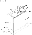
- FIG. 5 is an exploded perspective view schematically showing the jig for assembly of the battery module according to the embodiment of the present invention and the battery module.
- FIGS. 6 and 7 are views schematically showing the state in which the housing and the first protective cover of the jig for assembly of the battery module according to the embodiment of the present invention are operated.
- FIGS. 8 and 9 are views schematically showing the state in which the housing and the second protective cover of the jig for assembly of the battery module according to the embodiment of the present invention are operated.
- a battery module 10 assembled using a jig for assembly of a battery module according to an embodiment of the present invention, includes at least one battery cell 11 .
- the present invention is not limited as to the number of battery cells 11 .
- the plurality of battery cells 11 may be connected to each other by a casing or a fixing member 111 .
- the battery module 10 also includes a circuit board 12 connected to the battery cell 11 .
- the circuit board 12 may be a battery management unit (BMU).
- the circuit board 12 may include a protection circuit.
- a plurality of elements 141 and 142 may be loaded on the circuit board 12 .
- the plurality of elements 141 and 142 may include a resistor and a capacitor.
- the plurality of elements 141 and 142 may have different heights.
- connection member 13 such as a metal electrode or a wire, may extend from the battery cell 11 .
- the connection member 13 may electrically connect the plurality of battery cells 11 to each other.
- the circuit board 12 is provided with a soldering portion 127 , to which the connection member 13 is attached.
- An electrode, etc., connected to the connection member 13 may be provided at the soldering portion 127 .
- the connection member 13 may be attached to the soldering portion 127 by soldering.
- the battery module 10 is assembled such that the circuit board 12 is spaced apart from the battery cell 11 by a predetermined distance G.
- the circuit board 12 may be supported by the connection member 13 , whereby the orientation (the position or the height) of the circuit board 12 with respect to the battery cell 11 may be maintained. That is, the distance G between the circuit board 12 and the battery cell 11 may be maintained as the result of the circuit board 12 being supported by the connection member 13 .
- the present invention is not limited to the construction in which the circuit board 12 is supported by the connection member 13 , and the circuit board 12 may be supported by a separate member.
- the jig for assembly of the battery module serves to prevent unintentional movement of the circuit board 12 during the process in which the connection member 13 is attached to the soldering portion 127 of the circuit board 12 . That is, the battery cell 11 and the circuit board 12 may be supported by the jig 20 for assembly of the battery module during the process of attaching the connection member 13 to the soldering portion 127 of the circuit board 12 , whereby the orientation (the position or the height) of the circuit board 12 with respect to the battery cell 11 , i.e. the distance G between the circuit board 12 and the battery cell 11 , may be stably maintained.
- the jig 20 for assembly of the battery module may include a housing 21 having a first accommodation portion 211 , configured to accommodate the battery cell 11 , and a second accommodation portion 212 disposed so as to be spaced apart from the first accommodation portion 211 , the second accommodation portion 212 being configured to accommodate the circuit board 12 . Consequently, the battery cell 11 may be accommodated in the first accommodation portion 211 , and the circuit board 12 may be accommodated in the second accommodation portion 212 , whereby the orientation (the position or the height) of the circuit board 12 with respect to the battery cell 11 may be stably maintained.
- the housing 21 has an accommodation space partitioned by a partition wall 214 as the first accommodation portion 211 .
- the housing 21 an opening formed through the partition wall 214 as the second accommodation portion 212 .
- the second accommodation portion 212 (the opening) may be provided with a step portion 213 , on which the circuit board 12 is settled.
- the thickness T of the step portion 213 may be almost equal to or less than the distance G between the circuit board 12 and the battery cell 11 .
- the step portion 213 may be interposed between the circuit board 12 and the battery cell 11 .
- the distance G between the circuit board 12 and the battery cell 11 may be stably maintained. Consequently, even in the case in which external force is applied to the circuit board 12 , for example, when the circuit board 12 and/or the connection member 13 is pushed by a soldering tool (a soldering iron), the orientation (the position or the height) of the circuit board 12 with respect to the battery cell 11 may be stably maintained.
- the jig 20 for assembly of the battery module may include a first protective cover 22 configured to cover the battery cell 11 accommodated in the first accommodation portion 211 .
- the first protective cover 22 may serve to protect the battery cell 11 accommodated in the first accommodation portion 211 from the outside.
- the first protective cover 22 may serve to prevent the battery cell 11 from being arbitrarily separated from the first accommodation portion 211 .
- the jig 20 for assembly of the battery module may include a second protective cover 23 configured to cover the circuit board 12 accommodated in the second accommodation portion 212 .
- the second protective cover 23 may serve to protect the circuit board 12 accommodated in the second accommodation portion 212 from the outside.
- the second protective cover 23 may serve to protect the element 141 on the circuit board 12 accommodated in the second accommodation portion 212 from the outside during the process of attaching the connection member 13 to the soldering portion 127 .
- a through-hole 237 through which the soldering portion 127 of the circuit board 12 is exposed to the outside, may be formed in the second protective cover 23 .
- the soldering tool may access the soldering portion 127 of the circuit board 12 through the through-hole 237 , whereby the connection member 13 may be attached to the soldering portion 127 using the soldering tool.
- the second protective cover 23 may be provided with an element exposure hole 231 , through which the element 142 , the height of which is relatively large, among the plurality of elements 141 and 142 , is exposed to the outside. Since the element 142 is exposed to the outside through the element exposure hole 231 in the state in which the second protective cover 23 covers the circuit board 12 , therefore, the element 142 is prevented from colliding with the second protective cover 23 .
- the element exposure hole 231 may be disposed so as to be spaced apart from the through-hole 237 , whereby interference between the element 142 exposed through the element exposure hole 231 and the soldering tool may be prevented. Consequently, damage to the element 142 may be prevented during the process of attaching the connection member 13 to the soldering portion 127 .
- the jig 20 for assembly of the battery module may include a support unit 24 , at which the housing 21 is supported.
- the housing 21 may be detachably supported at the support unit 24 .
- the housing 21 may be supported at the support unit 24 in the state in which the battery module 10 is accommodated in the housing 21 .
- the support unit 24 may include a first support block 241 and a second support block 242 .
- the first support block 241 and the second support block 242 may be disposed at right angles to each other.
- the first support block 241 and the second support block 242 may be configured separably, or may be integrally formed.
- the first protective cover 22 may be connected to the first support block 241 so as to be turnable about a first hinge shaft 222 .
- the first protective cover 22 may cover the first accommodation portion 211 , or may expose the first accommodation portion 211 to the outside. That is, the first protective cover 22 may be turned about the first hinge shaft 222 between a closing position, at which the first accommodation portion 211 is covered, and an opening position, at which the first accommodation portion 211 is exposed to the outside.
- the first protective cover 22 may be provided with a first contact portion 223 configured to contact the housing 21 .
- the first contact portion 223 contacts a portion of the housing 21 when the housing 21 is moved in the state of being loaded on the support unit 24 .
- the first protective cover 22 may be turned about the first hinge shaft 222 as the result of the housing 21 being moved in the state of being in contact with the first contact portion 223 .
- the first protective cover 22 may cover the battery cell 11 accommodated in the first accommodation portion 211 . In this way, the first protective cover 22 may be automatically turned and may then cover the battery cell 11 when the housing 21 is loaded on the support unit 24 .
- a first spring 224 may be provided between the first protective cover 22 and the support unit 24 such that the first protective cover 22 can be returned to the original position thereof (the opening position) when the housing 21 is separated from the support unit 24 , i.e. when the force that the housing 21 applies to the first protective cover 22 through the first contact portion 223 is released.
- the first protective cover 22 may be turned about the first hinge shaft 222 and returned to the opening position thereof by the elastic restoring force of the first spring 224 .
- the second protective cover 23 may be connected to the second support block 242 so as to be turnable about a second hinge shaft 232 .
- the second protective cover 23 may cover the second accommodation portion 212 , or may expose the second accommodation portion 212 to the outside. That is, the second protective cover 23 may be turned about the second hinge shaft 232 between a closing position, at which the second accommodation portion 212 is covered, and an opening position, at which the second accommodation portion 212 is exposed to the outside.
- the second protective cover 23 may be provided with a second contact portion 233 configured to contact the housing 21 .
- the second contact portion 233 contacts a portion of the housing 21 when the housing 21 is moved in the state of being loaded on the support unit 24 .
- the second protective cover 23 may be turned about the second hinge shaft 232 as the result of the housing 21 being moved in the state of being in contact with the second contact portion 233 .
- the second protective cover 23 may cover the circuit board 12 accommodated in the second accommodation portion 212 . In this way, the second protective cover 23 may be automatically turned and may then cover the circuit board 12 when the housing 21 is loaded on the support unit 24 .
- a second spring 234 may be provided between the second protective cover 23 and the support unit 24 such that the second protective cover 23 can be returned to the original position thereof (the opening position) when the housing 21 is separated from the support unit 24 , i.e. when the force that the housing 21 applies to the second protective cover 23 through the second contact portion 233 is released.
- the second protective cover 23 may be turned about the second hinge shaft 232 and returned to the opening position thereof by the elastic restoring force of the second spring 234 .
- the battery cell 11 is accommodated in the first accommodation portion 211
- the circuit board 12 is accommodated in the second accommodation portion 212 , which is disposed so as to be spaced apart from the first accommodation portion 211 , in the state of being spaced apart from the battery cell 11 .
- connection member 13 may be attached to a desired position on the soldering portion 127 of the circuit board 12 .
Landscapes
- Engineering & Computer Science (AREA)
- Chemical & Material Sciences (AREA)
- Chemical Kinetics & Catalysis (AREA)
- Electrochemistry (AREA)
- General Chemical & Material Sciences (AREA)
- Microelectronics & Electronic Packaging (AREA)
- Manufacturing & Machinery (AREA)
- Mechanical Engineering (AREA)
- Battery Mounting, Suspending (AREA)
Abstract
Description
Claims (13)
Applications Claiming Priority (2)
| Application Number | Priority Date | Filing Date | Title |
|---|---|---|---|
| KR1020180108014A KR102627945B1 (en) | 2018-09-10 | 2018-09-10 | Jig for assembling battery module |
| KR10-2018-0108014 | 2018-09-10 |
Publications (2)
| Publication Number | Publication Date |
|---|---|
| US20200083500A1 US20200083500A1 (en) | 2020-03-12 |
| US10897032B2 true US10897032B2 (en) | 2021-01-19 |
Family
ID=69719743
Family Applications (1)
| Application Number | Title | Priority Date | Filing Date |
|---|---|---|---|
| US16/537,440 Active 2039-09-16 US10897032B2 (en) | 2018-09-10 | 2019-08-09 | Jig for assembly of battery module |
Country Status (2)
| Country | Link |
|---|---|
| US (1) | US10897032B2 (en) |
| KR (1) | KR102627945B1 (en) |
Families Citing this family (3)
| Publication number | Priority date | Publication date | Assignee | Title |
|---|---|---|---|---|
| CN111668504B (en) * | 2020-05-09 | 2024-02-09 | 惠州金源精密自动化设备有限公司 | Overturning jig mechanism and battery |
| KR102915128B1 (en) * | 2020-09-17 | 2026-01-20 | 삼성전자주식회사 | Battery and electronic device including the same |
| CN116900973A (en) * | 2023-07-02 | 2023-10-20 | 长兴太湖能谷科技有限公司 | An installation and positioning fixture for battery conduits |
Citations (9)
| Publication number | Priority date | Publication date | Assignee | Title |
|---|---|---|---|---|
| JP2011210529A (en) | 2010-03-30 | 2011-10-20 | Toray Eng Co Ltd | Battery assembly jig, battery assembly device using the same |
| KR20120051808A (en) | 2010-11-15 | 2012-05-23 | 현대자동차주식회사 | Battery module having an improved assembly |
| US20130143082A1 (en) | 2011-12-01 | 2013-06-06 | Myung-Chul Kim | Battery module |
| KR20150141811A (en) | 2014-06-10 | 2015-12-21 | 주식회사 엘지화학 | Jig device for battery cell |
| KR20150141810A (en) | 2014-06-10 | 2015-12-21 | 주식회사 엘지화학 | Jig device for battery cell |
| KR20170048819A (en) | 2015-10-27 | 2017-05-10 | 주식회사 엘지화학 | Battery Pack Including Static Guide Pattern |
| KR20170048804A (en) | 2015-10-27 | 2017-05-10 | 주식회사 엘지화학 | Battery Pack Including Static Guide Member |
| US20180205107A1 (en) * | 2017-01-19 | 2018-07-19 | Lg Chem, Ltd. | Jig having variable structure depending on size of receiving portion of case |
| KR20180092595A (en) | 2017-02-10 | 2018-08-20 | 주식회사 엘지화학 | Jig for Assembling Battery Module and Circuit Member |
Family Cites Families (3)
| Publication number | Priority date | Publication date | Assignee | Title |
|---|---|---|---|---|
| KR101023873B1 (en) * | 2008-12-23 | 2011-03-22 | 삼성에스디아이 주식회사 | Secondary battery having protection circuit module and manufacturing method thereof |
| KR101234240B1 (en) * | 2011-02-11 | 2013-02-18 | 삼성에스디아이 주식회사 | Battery pack having partition wall between core pack and protection circuit module |
| KR20140140744A (en) * | 2013-05-30 | 2014-12-10 | 삼성에스디아이 주식회사 | Battery module |
-
2018
- 2018-09-10 KR KR1020180108014A patent/KR102627945B1/en active Active
-
2019
- 2019-08-09 US US16/537,440 patent/US10897032B2/en active Active
Patent Citations (11)
| Publication number | Priority date | Publication date | Assignee | Title |
|---|---|---|---|---|
| JP2011210529A (en) | 2010-03-30 | 2011-10-20 | Toray Eng Co Ltd | Battery assembly jig, battery assembly device using the same |
| KR20120051808A (en) | 2010-11-15 | 2012-05-23 | 현대자동차주식회사 | Battery module having an improved assembly |
| US20130143082A1 (en) | 2011-12-01 | 2013-06-06 | Myung-Chul Kim | Battery module |
| KR20130061375A (en) | 2011-12-01 | 2013-06-11 | 삼성에스디아이 주식회사 | Battery module |
| US9077020B2 (en) | 2011-12-01 | 2015-07-07 | Samsung Sdi Co., Ltd. | Battery module |
| KR20150141811A (en) | 2014-06-10 | 2015-12-21 | 주식회사 엘지화학 | Jig device for battery cell |
| KR20150141810A (en) | 2014-06-10 | 2015-12-21 | 주식회사 엘지화학 | Jig device for battery cell |
| KR20170048819A (en) | 2015-10-27 | 2017-05-10 | 주식회사 엘지화학 | Battery Pack Including Static Guide Pattern |
| KR20170048804A (en) | 2015-10-27 | 2017-05-10 | 주식회사 엘지화학 | Battery Pack Including Static Guide Member |
| US20180205107A1 (en) * | 2017-01-19 | 2018-07-19 | Lg Chem, Ltd. | Jig having variable structure depending on size of receiving portion of case |
| KR20180092595A (en) | 2017-02-10 | 2018-08-20 | 주식회사 엘지화학 | Jig for Assembling Battery Module and Circuit Member |
Also Published As
| Publication number | Publication date |
|---|---|
| US20200083500A1 (en) | 2020-03-12 |
| KR102627945B1 (en) | 2024-01-22 |
| KR20200029318A (en) | 2020-03-18 |
Similar Documents
| Publication | Publication Date | Title |
|---|---|---|
| US7914924B2 (en) | Stacked battery pack housing | |
| US10461288B2 (en) | Battery module and battery pack including same | |
| CN108780860B (en) | Battery pack for vehicle and vehicle including battery pack | |
| US10897032B2 (en) | Jig for assembly of battery module | |
| CN106469797B (en) | battery module with stand | |
| EP3926735A1 (en) | Battery pack, electronic device, and vehicle | |
| US10541452B2 (en) | Battery pack including circuit board having protruding surface | |
| JP2013175442A (en) | Power storage device | |
| CN105981198B (en) | wiring module | |
| KR20170040638A (en) | Battery module and battery pack including the same | |
| KR20180015494A (en) | Battery Pack | |
| JP7045600B2 (en) | Battery pack containing electrical assembly and said electrical assembly | |
| KR101833567B1 (en) | Tray for charge and discharge regulator having a fixed function of battery cell | |
| JP2001068078A (en) | Battery | |
| US5920178A (en) | Battery pack having integrated charging circuit and charging connector and method of forming same | |
| US9911961B2 (en) | Energy storage apparatus | |
| CN115136403A (en) | Battery pack, power storage device, and vehicle | |
| CN114731050A (en) | Power supply transformation module, charger, power supply assembly and movable platform assembly | |
| KR20170021561A (en) | Battery pack | |
| CN115917834B (en) | Battery module, battery pack including the battery module, and electric vehicle | |
| US7531985B2 (en) | Pack case for secondary battery | |
| KR102591513B1 (en) | Battery Pack | |
| KR20130080212A (en) | Battery pack | |
| JP4370412B2 (en) | Pack battery | |
| KR20060027277A (en) | Pack case for secondary battery |
Legal Events
| Date | Code | Title | Description |
|---|---|---|---|
| FEPP | Fee payment procedure |
Free format text: ENTITY STATUS SET TO UNDISCOUNTED (ORIGINAL EVENT CODE: BIG.); ENTITY STATUS OF PATENT OWNER: LARGE ENTITY |
|
| AS | Assignment |
Owner name: LG CHEM, LTD., KOREA, REPUBLIC OF Free format text: ASSIGNMENT OF ASSIGNORS INTEREST;ASSIGNORS:SONG, SONG YI;BAEK, JU HWAN;PARK, HEUNG KUN;REEL/FRAME:050340/0818 Effective date: 20190723 |
|
| STPP | Information on status: patent application and granting procedure in general |
Free format text: NOTICE OF ALLOWANCE MAILED -- APPLICATION RECEIVED IN OFFICE OF PUBLICATIONS |
|
| STPP | Information on status: patent application and granting procedure in general |
Free format text: PUBLICATIONS -- ISSUE FEE PAYMENT VERIFIED |
|
| STCF | Information on status: patent grant |
Free format text: PATENTED CASE |
|
| AS | Assignment |
Owner name: LG ENERGY SOLUTION, LTD., KOREA, REPUBLIC OF Free format text: ASSIGNMENT OF ASSIGNORS INTEREST;ASSIGNOR:LG CHEM, LTD.;REEL/FRAME:058295/0068 Effective date: 20211027 Owner name: LG ENERGY SOLUTION, LTD., KOREA, REPUBLIC OF Free format text: ASSIGNMENT OF ASSIGNOR'S INTEREST;ASSIGNOR:LG CHEM, LTD.;REEL/FRAME:058295/0068 Effective date: 20211027 |
|
| MAFP | Maintenance fee payment |
Free format text: PAYMENT OF MAINTENANCE FEE, 4TH YEAR, LARGE ENTITY (ORIGINAL EVENT CODE: M1551); ENTITY STATUS OF PATENT OWNER: LARGE ENTITY Year of fee payment: 4 |